JP2014202055A - Double glazing with glazing channel - Google Patents
Double glazing with glazing channel Download PDFInfo
- Publication number
- JP2014202055A JP2014202055A JP2013081975A JP2013081975A JP2014202055A JP 2014202055 A JP2014202055 A JP 2014202055A JP 2013081975 A JP2013081975 A JP 2013081975A JP 2013081975 A JP2013081975 A JP 2013081975A JP 2014202055 A JP2014202055 A JP 2014202055A
- Authority
- JP
- Japan
- Prior art keywords
- glass
- glazing channel
- sealing material
- inner bottom
- multilayer glass
- Prior art date
- Legal status (The legal status is an assumption and is not a legal conclusion. Google has not performed a legal analysis and makes no representation as to the accuracy of the status listed.)
- Withdrawn
Links
Images


Abstract
Description
本発明は、グレージングチャンネル付き複層ガラスに関する。 The present invention relates to a multilayer glass with a glazing channel.
従来、住宅用窓は、複層ガラスの周縁部がグレージングチャネルによって被覆されたグレージングチャンネル付き複層ガラスと、グレージングチャンネル付き複層ガラスの周縁部に嵌め込まれる框と窓枠とによって構成される(特許文献1参照)。 Conventionally, a residential window is composed of a double-glazed glass with a glazing channel in which the peripheral edge of the double-glazed glass is covered with a glazing channel, and a window and a window frame fitted into the peripheral edge of the double-glazed glass with a glazing channel ( Patent Document 1).
特許文献1のグレージングチャンネルは、底壁部と、底壁部の長さ方向の両側縁に立設された一対の側壁部とを有する断面略コ字形状に構成され、底壁部の内底面が複層ガラスの周縁部の端面に対向するように複層ガラスの周縁部に被覆される。 The glazing channel of Patent Document 1 has a substantially U-shaped cross section having a bottom wall portion and a pair of side wall portions erected on both side edges in the length direction of the bottom wall portion, and an inner bottom surface of the bottom wall portion. Is coated on the peripheral edge of the multilayer glass so as to face the end face of the peripheral edge of the multilayer glass.
一方、図10に示す特許文献2のグレージングチャンネル1は、底壁部2の内底面2aに隆条部3が一体に備えられている。この隆条部3は、底壁部2の幅B方向の中央部に、底壁部2の長さL方向に沿って備えられた1本の凸条部である。 On the other hand, in the glazing channel 1 of Patent Document 2 shown in FIG. 10, the ridge portion 3 is integrally provided on the inner bottom surface 2 a of the bottom wall portion 2. The ridge 3 is a single ridge provided along the length L direction of the bottom wall 2 at the center in the width B direction of the bottom wall 2.
隆条部3の先端には、略碇形状(矢印形状ともいう)のアンカー部4が備えられており、このアンカー部4が、複層ガラスの端面の溝に充填された固化前のシール材(いわゆる二次シール材)に押し込まれて二次シール材に固着される。したがって、特許文献2のグレージングチャンネル付き複層ガラスは、隆条部3を備えていないものと比較して、複層ガラスに対するグレージングチャンネル1の保持力が向上されている。 At the tip of the ridge portion 3, an anchor portion 4 having a substantially bowl shape (also referred to as an arrow shape) is provided, and the anchor portion 4 is a sealing material before solidification filled in a groove on the end surface of the multilayer glass. It is pushed into (so-called secondary sealing material) and fixed to the secondary sealing material. Accordingly, the double-glazed glass with a glazing channel of Patent Document 2 has improved holding power of the glazing channel 1 with respect to the double-glazed glass as compared with the glass without the ridge 3.
ところで、最近の框は、ガラス窓の採光性を高めるために、見付けの幅を小さくする傾向にある(例えば、株式会社LIXIL製:商品名:SAMOS参照)。この傾向によって、グレージングチャンネル付き複層ガラスの周縁部が嵌め込まれる框の溝の深さが浅くなり、この浅い溝のなかにグレージングチャンネルを収めなければならず、この結果、複層ガラスに対するグレージングチャンネルの保持力が低下するという問題があった。特許文献2のグレージングチャンネルは、上記問題を改善すべくなされたものである。 By the way, in recent days, in order to improve the daylighting property of the glass window, there is a tendency to reduce the width of the finding (for example, see LIXIL Corporation: trade name: SAMOS). Due to this tendency, the depth of the ridge groove into which the peripheral edge of the glazed multi-layer glass is fitted becomes shallow, and the glazing channel must be contained in this shallow groove, and as a result, the glazing channel for the multi-layer glass. There was a problem that the holding power of the lowering. The glazing channel of Patent Document 2 has been made to improve the above problem.
なお、グレージングチャンネルの材料としては、樹脂製のポリ塩化ビニル(PVC)が一般的である。また、複層ガラスの二次シール材としては、ポリサルファイド、シリコーン、ウレタン等の硬化性エラストマをベースとし、ガラスとの接着性を発現するために適当な変性を加えられたものが一般的に使用されている。 As a material for the glazing channel, resin-made polyvinyl chloride (PVC) is generally used. Also, as the secondary sealing material for multi-layer glass, generally used are those based on curable elastomers such as polysulfide, silicone, urethane, etc., which have been modified appropriately to develop adhesion to glass. Has been.
複層ガラスの各辺の周縁部に沿って被覆されたグレージングチャンネルは、それぞれのコーナー部で接合されているが、ガラスとグレージングチャンネルの材料との線熱膨張係数の相違、及びグレージングチャンネルが樹脂製の場合は樹脂の持つ加熱収縮率によって、長期間の屋内外での使用によりコーナー部の接合力が低下して、コーナー部に『口開き(グレージングチャンネルの接合端部に隙間、剥がれが生じる現象)』と称される欠点が発生することが市場で確認されている。 The glazing channels coated along the peripheral edge of each side of the multilayer glass are joined at the respective corners, but the difference in linear thermal expansion coefficient between the glass and the material of the glazing channel, and the glazing channel is a resin. In the case of the product, due to the heat shrinkage rate of the resin, the joint strength of the corner portion decreases due to long-term indoor / outdoor use, and a “open mouth (gap and peeling occurs at the joint end of the glazing channel). It has been confirmed in the market that a defect called “phenomenon)” occurs.
複層ガラスの二次シール材は、複層ガラスのアルミニウム製のスペーサとの接合力は強いが、樹脂製のグレージングチャンネルとの接合力は非常に弱い。すなわち、特許文献2のような隆条部3を備えることで複層ガラスに対するグレージングチャンネルの保持力は向上するが、前述した線熱膨張係数の相違と加熱収縮率とに起因して発生する前記『口開き』の欠点は解消することができなかった。 The secondary sealing material of the double-glazed glass has a strong bonding force with the aluminum spacer of the double-glazed glass, but has a very weak bonding force with the resin glazing channel. That is, the holding power of the glazing channel with respect to the multilayer glass is improved by providing the ridge portion 3 as in Patent Document 2, but the above-mentioned difference occurs due to the difference in the linear thermal expansion coefficient and the heat shrinkage rate. The disadvantage of “open mouth” could not be solved.
本発明は、このような事情に鑑みてなされたもので、樹脂製のグレージングチャンネルを使用した場合の『口開き』の欠点を解消できるグレージングチャンネル付き複層ガラスを提供することを目的とする。 The present invention has been made in view of such circumstances, and an object of the present invention is to provide a multi-layer glass with a glazing channel capable of eliminating the drawback of “open mouth” when a resin glazing channel is used.
前記目的を達成するために本発明の一態様は、複数枚のガラス板が空気層を介して重ねられ、かつ前記複数枚のガラス板がその周縁部でシール材によって接着された複層ガラスと、底壁部及び前記底壁部の長さ方向に沿った両側縁に立設された側壁部とからなるグレージングチャンネルを備えたグレージングチャンネル付き複層ガラスにおいて、前記複層ガラスの前記シール材と前記グレージングチャンネルの前記底壁部の内底面との間に、前記シール材と前記内底面とを接合させる接合部材が介在されたことを特徴とするグレージングチャンネル付き複層ガラスを提供する。 In order to achieve the above object, one embodiment of the present invention includes a multilayer glass in which a plurality of glass plates are stacked via an air layer, and the plurality of glass plates are bonded together by a sealing material at a peripheral portion thereof. A double-glazed glass with a glazing channel comprising a bottom wall portion and side wall portions erected on both side edges along the length direction of the bottom wall portion, and the sealing material of the double-glazed glass, Provided is a multilayer glass with a glazing channel, wherein a joining member for joining the sealing material and the inner bottom surface is interposed between the inner bottom surface of the bottom wall portion of the glazing channel.
本願の発明者は、複層ガラスのシール材(二次シール材)とグレージングチャンネルの底壁部の内底面との間に、シール材と内底面とを接合させる接合部材を介在させることによって、グレージングチャンネルと複層ガラスとを強固に接合させ、グレージングチャンネルの外気温度の変化による伸縮を、複層ガラスに拘束させて複層ガラスと同量の伸縮量とすることにより、『口開き』の欠点を解消できることを見出した。 The inventor of the present application interposes a joining member that joins the sealing material and the inner bottom surface between the sealing material of the multilayer glass (secondary sealing material) and the inner bottom surface of the bottom wall portion of the glazing channel, By firmly bonding the glazing channel and the double-glazed glass, and constricting the expansion and contraction due to changes in the outside temperature of the glazing channel to the double-glazed glass, the amount of expansion and contraction is the same as the double-glazed glass. It was found that the drawbacks can be eliminated.
これにより、本発明の一態様によれば、樹脂製のグレージングチャンネルを使用した場合の『口開き』の欠点を解消できる。 Thereby, according to one aspect of the present invention, it is possible to eliminate the disadvantage of “open mouth” when a resin glazing channel is used.
本発明の一態様は、前記接合部材は、前記内底面に取り付けられたアルミ箔又はアルミニウム製のシートであることが好ましい。 In one aspect of the present invention, the joining member is preferably an aluminum foil or an aluminum sheet attached to the inner bottom surface.
本発明の一態様によれば、シール材と強固に接合する性質を備えた、厚さ200μm以下のアルミ箔、又は厚さ200μmを超えるアルミニウム製のシートを接合部材として適用することにより、本発明の目的を達成できる。 According to one aspect of the present invention, by applying an aluminum foil having a thickness of 200 μm or less, or an aluminum sheet having a thickness of more than 200 μm, which has a property of firmly bonding to a sealing material, the present invention Can achieve the purpose.
本発明の一態様は、前記アルミ箔又はアルミニウム製のシートは、前記内底面に備えられた隆条部の表面に取り付けられることが好ましい。 In one embodiment of the present invention, the aluminum foil or the aluminum sheet is preferably attached to a surface of a ridge provided on the inner bottom surface.
本発明の一態様によれば、アルミ箔又はアルミニウム製のシートによる接合力の向上と、隆条部による保持力の向上とを同時に達成できる。 According to one aspect of the present invention, it is possible to simultaneously achieve an increase in bonding force with an aluminum foil or aluminum sheet and an increase in holding force with a ridge.
本発明の一態様は、前記接合部材は、前記内底面及び前記シール部材のうち一方に塗布されるプライマーであることが好ましい。 In one aspect of the present invention, the joining member is preferably a primer applied to one of the inner bottom surface and the seal member.
本発明の一態様によれば、プライマーを塗布することにより、本発明の目的を達成できる。 According to one embodiment of the present invention, the object of the present invention can be achieved by applying a primer.
本発明の一態様は、前記プライマーは、前記内底面に備えられた隆条部の表面に塗布されることが好ましい。 In one aspect of the present invention, the primer is preferably applied to a surface of a ridge portion provided on the inner bottom surface.
本発明の一態様によれば、プライマーによる接合力の向上と、隆条部による保持力の向上とを同時に達成できる。 According to one aspect of the present invention, it is possible to simultaneously achieve an increase in the bonding force by the primer and an increase in the holding force by the ridge.
本発明の一態様は、前記グレージングチャンネルはポリ塩化ビニル製であり、前記シール材はポリサルファイド、シリコーン、又はウレタンであることが好ましい。 In one embodiment of the present invention, the glazing channel is preferably made of polyvinyl chloride, and the sealing material is preferably polysulfide, silicone, or urethane.
ポリ塩化ビニルはグレージングチャンネルの材料として一般的に使用されており、ポリサルファイド、シリコーン、又はウレタンはシール材として一般的に使用されている。これらの組み合わせにおいても、本発明の接合部材を適用すれば、本発明の目的を達成できる。 Polyvinyl chloride is commonly used as a material for glazing channels, and polysulfide, silicone, or urethane is commonly used as a sealing material. Even in these combinations, the object of the present invention can be achieved by applying the joining member of the present invention.
以上の如く、本発明の態様によれば、樹脂製のグレージングチャンネルにアルミ箔又はアルミニウム製のシートを被覆する構成、及び樹脂製のグレージングチャンネルとシール材とを接着させる目的のプライマーをグレージングチャンネル又はシール材の露出面に塗布する構成によって、『口開き』の欠点を解消できる。 As described above, according to the aspect of the present invention, a resin glazing channel is coated with an aluminum foil or an aluminum sheet, and a primer for the purpose of bonding a resin glazing channel and a sealant is added to the glazing channel or By applying to the exposed surface of the sealing material, the drawback of “open mouth” can be solved.
なお、外気温度の変化によるグレージングチャンネルの伸縮を複層ガラスによって拘束させるために、アルミ箔、アルミニウム製のシート、プライマーは、グレージングチャンネルの全長に渡って配置、塗布することが好ましい。 In order to constrain the expansion and contraction of the glazing channel due to a change in the outside air temperature with the double glazing, the aluminum foil, the aluminum sheet, and the primer are preferably arranged and applied over the entire length of the glazing channel.
以上説明したように本発明のグレージングチャンネル付き複層ガラスによれば、樹脂製のグレージングチャンネルを使用した場合の『口開き』の欠点を解消できる。 As described above, according to the double-glazed glass with a glazing channel of the present invention, it is possible to eliminate the drawback of “open mouth” when a resin-made glazing channel is used.
以下添付図面に基づいて、本発明の実施の形態に係るグレージングチャンネル付き複層ガラスについて説明する。 Hereinafter, a multi-layer glass with a glazing channel according to an embodiment of the present invention will be described with reference to the accompanying drawings.
〔第1の実施形態のグレージングチャンネル付き複層ガラスについて〕
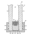
図1は、第1の実施形態に係るグレージングチャンネル(以下、GCと言う。)付き複層ガラス10の要部断面図であり、GC12が複層ガラス14の周縁部に装着された要部拡大縦断面図である。すなわち、GC付き複層ガラス10は、CG12と複層ガラス14とから構成される。
[About the multi-layer glass with glazing channel of the first embodiment]
FIG. 1 is a cross-sectional view of a main part of a multi-layer glass 10 with a glazing channel (hereinafter referred to as GC) according to the first embodiment, and an enlarged main part in which GC 12 is attached to the peripheral part of the
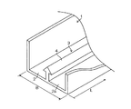
また、図2は、GC12の要部を拡大して示した斜視図であり、図1のGC12よりも形状を簡略化して示した図である。 FIG. 2 is an enlarged perspective view showing a main part of the GC 12, and is a diagram showing a simplified shape as compared with the GC 12 of FIG.
〈複層ガラス14について〉
図1に示すように、複層ガラス14を構成する少なくとも2枚のガラス板16、18は、その間に中間層20が画成されるように、スペーサ22を介して隔置される。スペーサ22は、ガラス板16とガラス板18との間隔が一定に保持されるように、ガラス板16とガラス板18の対向する内側主面16a、18aの側縁部に沿って配置される。
<About the
As shown in FIG. 1, at least two
スペーサ22は、ガラス板16の内側主面16aと対向する面が、一次シール材24によってガラス板16の内側主面16aに接着される。また、スペーサ22は、ガラス板18の内側主面18aと対向する面が、一次シール材24によってガラス板18の内側主面18aに接着される。更に、スペーサ22の外側(中間層20と反対側)には、ガラス板16とガラス板18との間に形成される凹状の溝に二次シール材(シール材)26が充填される。二次シール材26は、一次シール材24に接するように充填される。一次シール材24と二次シール材26とによって、ガラス板16とガラス板18との間に画成される中間層20が外気から遮断される。
The
スペーサ22は、中空状に構成されており、スペーサ22の内側(中間層20側)の面には、スペーサ22の長手方向(紙面に垂直な方向)に沿って通気孔28が所定の間隔で備えられている。通気孔28は、スペーサ22の中空部に貫通されており、これによって、前記中空部と中間層20とが連通されている。また、前記中空部には、粒状ゼオライト等の乾燥剤30が充填されているので、中間層20の空気が通気孔28を介して乾燥剤30によって乾燥される。
The
スペーサ22としては、アルミニウムを主材質とする金属製スペーサが使用されるが、スペーサ本体を硬質の樹脂製としてその表面にアルミニウムシートを被覆したスペーサを使用してもよい。
As the
また、一次シール材24としては、通常架橋処理されないブチルゴム、又はポリイソブチレンをベースとし、着色と補強を目的としたカーボンブラック等のフィラーを含有せしめたものが好適である。なお、一次シール24は固化せず、粘着のみ有するため、いわゆる『複層ガラスとしてのスペーサー〜ガラス間の接合力』は二次シール26の接合力にゆだねている。
Further, as the
更に、二次シール材26としては、ポリサルファイド(横浜ゴム株式会社製:商品名:ハマタイトSM9000)、シリコーン(東レ・ダウコーニング株式会社製:商品名:SE936)、ウレタン(サンユレック株式会社製:商品名:SANYU IGS205)等の硬化性エラストマをベースとし、ガラスとの接着性を発現するために適当な変性を加えられたもの等が好適である。
Further, as the
〈GC12について〉
CG12は、複層ガラス10の周縁部に装着されて、框(不図示)の溝との間の介装材として機能する。
<About GC12>
The CG 12 is mounted on the peripheral edge of the double-glazed glass 10 and functions as an interposition material between the groove (not shown).
GC12は、図1、図2の如く底壁部32と、底壁部32の長さ方向の両側縁に立設された一対の側壁部34、34とからなる硬質保持部材を備え、断面形状が略コ字形を呈している。また、GC12は、図1の如く側壁部34、34の対向面34a、34aに軟質樹脂からなるリップ部材36、36をそれぞれ備える。GC12は、底壁部32の内底面32aが複層ガラス14の周縁部の端面に対向するように複層ガラス14の周縁部に取り付けられる。
As shown in FIGS. 1 and 2, the GC 12 includes a hard holding member including a
GC12の前記硬質保持部材は、ポリ塩化ビニル等の樹脂製である。リップ部材36は、GC12に複層ガラス14の周縁部が装着された際に、複層ガラス14の側縁部に弾性をもって密着される。
The hard holding member of the GC 12 is made of a resin such as polyvinyl chloride. The
〈GC付き複層ガラス10の特徴について〉
第1の実施形態のGC付き複層ガラス10は、複層ガラス14の二次シール材26とCG12の底壁部32の内底面32aとの間に、二次シール材26と内底面32aとを接合させる、厚さが200μm以下のアルミ箔(接合部材)38が介在されている。アルミ箔38は、特にポリサルファイドの二次シール材26に強固に接合される性質を備えており、内底面32aのうち、二次シール材26と対向する面に接着剤(住友3M株式会社製:商品名:DP−110)によって接着されている。また、アルミ箔38はGC12の全長に渡って備えられている。
<About the characteristics of the multi-layer glass 10 with GC>
The multilayer glass 10 with GC of the first embodiment includes a
このGC付き複層ガラス10によれば、アルミ箔38によってGC12と複層ガラス14とが強固に接合されている。これによって、GC12の外気温度の変化による、GC12の長手方向の伸縮が、複層ガラス14に拘束されて複層ガラス14と同量の伸縮量となる。
According to the multilayer glass 10 with GC, the GC 12 and the
したがって、GC付き複層ガラス10によれば、ポリ塩化ビニル等の樹脂製のGC12と複層ガラス14のガラスとの線熱膨張係数の差に起因する欠点、つまり、従来のGC付き複層ガラスで発生していた『口開き』の欠点を解消できる。
Therefore, according to the multi-layer glass with GC 10, there is a defect caused by the difference in linear thermal expansion coefficient between the GC12 made of resin such as polyvinyl chloride and the glass of the
なお、アルミ箔38に代えて、厚さが200μmを超えるアルミニウム製のシートを内底面32aに貼り付けても同様の効果を奏する。また、アルミ箔38又はアルミニウム製のシートを、二次シール材26の露出面に接合させた後、アルミ箔38又はアルミニウム製のシートを内底面32aに接着剤によって接着してもよい。更に、二次シール材26として、ポリサルファイド以外のシール材であるシリコーン及びウレタンであっても同様の効果を奏する。
In addition, it replaces with the
更にまた、アルミ箔38やアルミニウム製のシートの幅寸法を二次シール材26の幅寸法よりも短い、例えば1.5mm〜40mmとしても、GC12と複層ガラス14とを強固に接合できる。
Furthermore, even if the width dimension of the
〔第2の実施形態のGC付き複層ガラスについて〕
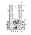
図3は、第2の実施形態に係るGC付き複層ガラス40の断面図であり、GC42が複層ガラス14の周縁部に装着された要部拡大縦断面図である。また、図4は、GC42の要部を拡大して示した斜視図であり、図3のGC42よりも形状を簡略化して示した図である。なお、図1、図2に示した第1の実施形態のGC付き複層ガラス10と同一又は類似の部材については同一の符号を付して、その説明は省略する。
[About the multi-layer glass with GC of the second embodiment]
FIG. 3 is a cross-sectional view of the multi-layer glass with GC 40 according to the second embodiment, and is an enlarged vertical cross-sectional view of a main part in which the
GC42の底壁部32の内底面32aには、隆条部44が備えられている。隆条部44は、内底面32aに対して垂直方向に突設されるとともに、内底面32aの幅方向の中央部であって、GC42の全長に渡って備えられている。
A
隆条部44は、内底面32aに突設された断面矩形状の凸条部46と、凸条部46の先端に備えられた略碇形状のアンカー部48とから構成される。アンカー部48は、GC42を複層ガラス14に装着した際に、複層ガラス14の固化前のポリサルファイドの二次シール材26に埋没される。
The
〈GC付き複層ガラス40の特徴について〉
第2の実施形態のGC付き複層ガラス40は、二次シール材26に埋没される隆条部44のアンカー部48の表面に、二次シール材26と内底面32aとを接合させる、厚さが200μm以下のアルミ箔(接合部材)50が接着されている。このアルミ箔50はGC12の全長に渡って備えられている。
<About the characteristics of the multilayer glass 40 with GC>
The multilayer glass 40 with GC of the second embodiment has a thickness that joins the
このGC付き複層ガラス40によれば、アルミ箔50によってGC42と複層ガラス14とが強固に接合されている。これによって、GC42の外気温度の変化による、GC42の長手方向の伸縮が、複層ガラス14に拘束されて複層ガラス14と同量の伸縮量となる。
According to the multilayer glass 40 with GC, the
したがって、GC付き複層ガラス40によれば、ポリ塩化ビニル等の樹脂製のGC42と複層ガラス14のガラスとの線熱膨張係数の差に起因する欠点、つまり、従来のGC付き複層ガラスで発生していた『口開き』の欠点を解消できる。また、隆条部44のアンカー部48が二次シール材26に埋没されることによって、複層ガラス14に対するGC42の保持力も向上する。
Therefore, according to the multi-layer glass 40 with GC, the disadvantage caused by the difference in linear thermal expansion coefficient between the
なお、アルミ箔50に代えて、厚さが200μmを超えるアルミニウム製のシートをアンカー部48の表面に貼り付けても同様の効果を奏する。また、二次シール材26として、ポリサルファイド以外のシール材であるシリコーン及びウレタンであっても同様の効果を奏する。
In addition, it replaces with the
〔第3の実施形態のGC付き複層ガラスについて〕
図5は、第3の実施形態に係るGC付き複層ガラス52の断面図であり、GC54が複層ガラス14の周縁部に装着された要部拡大縦断面図である。また、図6は、GC54の要部を拡大して示した斜視図であり、図5のGC54よりも形状を簡略化して示した図である。なお、図1、図2に示した第1の実施形態のGC付き複層ガラス10と同一又は類似の部材については同一の符号を付して、その説明は省略する。
[About the multi-layer glass with GC of the third embodiment]
FIG. 5 is a cross-sectional view of the multilayer glass 52 with GC according to the third embodiment, and is an enlarged vertical cross-sectional view of a main part in which the
〈GC付き複層ガラス52の特徴について〉
第3の実施形態のGC付き複層ガラス52は、図1、図2に示したアルミ箔38に代えて、接合部材としてプライマー(横浜ゴム株式会社製:商品名:ハマタイト プライマーNo.50IG)56が内底面32a又はポリサルファイドの二次シール材26の露出面26aに塗布されている。プライマー56は、GC54の全長に渡って塗布されている。
<About the characteristics of the multi-layer glass 52 with GC>
The multilayer glass 52 with GC of the third embodiment is replaced with a primer (manufactured by Yokohama Rubber Co., Ltd .: trade name: Hamatite Primer No. 50IG) 56 instead of the
このGC付き複層ガラス52によれば、プライマー56によってGC54と複層ガラス14とが強固に接合されている。これによって、GC54の外気温度の変化による、GC54の長手方向の伸縮が、複層ガラス14に拘束されて複層ガラス14と同量の伸縮量となる。
According to the multilayer glass 52 with GC, the
したがって、GC付き複層ガラス52によれば、ポリ塩化ビニル等の樹脂製のGC54と複層ガラス14のガラスとの線熱膨張係数の差に起因する欠点、つまり、従来のGC付き複層ガラスで発生していた『口開き』の欠点を解消できる。
Therefore, according to the multi-layer glass 52 with GC, the disadvantage caused by the difference in the linear thermal expansion coefficient between the
なお、二次シール材26として、ポリサルファイド以外のシール材であるシリコーン及びウレタンであっても同様の効果を奏する。ウレタンの場合のプライマーとしては、横浜ゴム株式会社製の「VC-100G(商品名)」、及びサンスター株式会社製の「435−73(商品名)」を使用できる。
In addition, even if it is silicone and urethane which are sealing materials other than polysulfide as the
また、プライマー56の塗布幅寸法を二次シール材26の幅寸法よりも短い、例えば1.5mm〜40mmとしても、GC54と複層ガラス14とを強固に接合できる。
Moreover, even if the application | coating width dimension of the
〔第4の実施形態のGC付き複層ガラスについて〕
図7は、第4の実施形態に係るGC付き複層ガラス58の断面図であり、GC60が複層ガラス14の周縁部に装着された要部拡大縦断面図である。また、図8は、GC60の要部を拡大して示した斜視図であり、図7のGC60よりも形状を簡略化して示した図である。なお、図3、図4に示した第2の実施形態のGC付き複層ガラス40と同一又は類似の部材については同一の符号を付して、その説明は省略する。
[About the multi-layer glass with GC of the fourth embodiment]
FIG. 7 is a cross-sectional view of the multi-layer glass with GC 58 according to the fourth embodiment, and is an enlarged vertical cross-sectional view of a main part in which the GC 60 is mounted on the peripheral edge of the
〈GC付き複層ガラス58の特徴について〉
第4の実施形態のGC付き複層ガラス58は、図1、図2に示したアルミ箔50に代えて、隆条部44のアンカー部48の表面に、プライマー(横浜ゴム株式会社製:商品名:ハマタイト プライマーNo.50IG)62を塗布したものである。
<About the characteristics of the multi-layer glass 58 with GC>
The multilayer glass 58 with GC of the fourth embodiment is replaced with a primer (manufactured by Yokohama Rubber Co., Ltd .: product) on the surface of the
このGC付き複層ガラス58によれば、プライマー62によってGC60と複層ガラス14とが強固に接合されている。これによって、GC60の外気温度の変化による、GC60の長手方向の伸縮が、複層ガラス14に拘束されて複層ガラス14と同量の伸縮量となる。
According to the multilayer glass 58 with GC, the GC 60 and the
したがって、GC付き複層ガラス58によれば、ポリ塩化ビニル等の樹脂製のGC60と複層ガラス14のガラスとの線熱膨張係数の差に起因する欠点、つまり、従来のGC付き複層ガラスで発生していた『口開き』の欠点を解消できる。隆条部44のアンカー部48が二次シール材26に埋没されることによって、複層ガラス14に対するGC42の保持力も向上する。
Therefore, according to the multi-layer glass 58 with GC, the disadvantage caused by the difference in linear thermal expansion coefficient between the GC60 made of resin such as polyvinyl chloride and the glass of the
なお、プライマー62を図8の如く、凸条部46全体に塗布するのではなく、凸条部46の側面には塗布しなくてもよい。また、二次シール材26として、ポリサルファイドのほか、シリコーン及びウレタンであっても同様の効果を奏する。ウレタンの場合のプライマーとしては、横浜ゴム株式会社製の「VC-100G(商品名)」、及びサンスター株式会社製の「435−73(商品名)」を使用できる。
The
〔他の実施形態〕
図9(A)は、GC12の内面全体にアルミ箔38を接着又はプライマー56を塗布したGC付き複層ガラス64の断面図である。図9(B)は、GC42の内面全体にアルミ箔50を接着又はプライマー62を塗布したGC付き複層ガラス66の断面図である。
[Other Embodiments]
FIG. 9A is a cross-sectional view of a multilayer glass 64 with GC in which an
つまり、図1〜図9に示したように、アルミ箔又はプライマーは、GCとの強い接合力を有するので、GCの内面の任意の一部分に接着又は塗布されていても良い。 That is, as shown in FIGS. 1 to 9, since the aluminum foil or primer has a strong bonding force with the GC, it may be adhered or applied to any part of the inner surface of the GC.
〈ガラスとポリ塩化ビニルの持つ線熱膨張係数の相違による影響〉
a)1辺が2500mmの複層ガラスについて、シミュレーション(−20〜+60℃)した結果、GCの端末のみに応力が発生したが、この応力は接合部材による接合強度に比べて極めて小さな力であった。よって、従来の『口開き』の欠点は発生しない。
<Effects of differences in coefficient of linear thermal expansion between glass and polyvinyl chloride>
a) As a result of simulation (−20 to + 60 ° C.) for a multi-layer glass having a side of 2500 mm, stress was generated only at the end of the GC, but this stress was extremely small compared to the bonding strength of the bonding member. It was. Therefore, the disadvantage of the conventional “open mouth” does not occur.
b)1辺が2500mmの複層ガラスについて、実測(−20〜+60℃)した結果、ガラスの線熱膨張係数に依存した寸法変化のみであった。よって、従来の『口開き』の欠点は発生しなかった。 b) As a result of actual measurement (-20 to + 60 ° C.) of the multilayer glass having a side of 2500 mm, only a dimensional change depending on the linear thermal expansion coefficient of the glass was obtained. Therefore, the disadvantage of the conventional “open mouth” did not occur.
〈加熱収縮率による影響〉
JIS A5756 項6.12に準拠した加熱収縮率試験によって求められた、第1から第4の実施形態のGC付き複層ガラス10、40、52、58のそれぞれのGC12、42、54、60の加熱収縮率は0.05%未満であった。そして、『口開き』の欠点が発生しないことを確認した。
<Effect of heat shrinkage>
Heat shrinkage of GC12, 42, 54, 60 of each of multilayer glass 10, 40, 52, 58 with GC of the first to fourth embodiments obtained by a heat shrinkage rate test in accordance with JIS A5756 clause 6.12 The rate was less than 0.05%. And it was confirmed that there was no defect of “open mouth”.
〔比較例〕
接合部材を使用しないGC付き複層ガラスでは、特にガラスとGCの持つ線熱膨張係数の相違によって、実際の外気温度の変化により発生する樹脂(ポリ塩化ビニル)製のGCの寸法変化に相当する「応力」が、GCの各コーナー部位に「荷重」として負荷が加わる。このため、経年変化によって『口開き』の欠点が発生する。
[Comparative Example]
In the multi-layer glass with GC that does not use a joining member, it corresponds to a dimensional change of GC made of resin (polyvinyl chloride) generated by a change in the actual outside air temperature due to a difference in linear thermal expansion coefficient between the glass and the GC. “Stress” is applied as a “load” to each corner portion of the GC. For this reason, the “open mouth” defect occurs due to secular change.
10…GC付き複層ガラス、12…GC、14…複層ガラス、16…ガラス板、18…ガラス板、20…中間層、22…スペーサ、24…一次シール材、26…二次シール材、28…通気孔、30…乾燥剤、32…底壁部、34…側壁部、36…リップ部材、38…アルミ箔、40…GC付き複層ガラス、42…GC、44…隆条部、46…凸条部、48…アンカー部、50…アルミ箔、52…GC付き複層ガラス、54…GC、56…プライマー、58…GC付き複層ガラス、60…GC、62…プライマー、64、66…GC付き複層ガラス DESCRIPTION OF SYMBOLS 10 ... Multi-layer glass with GC, 12 ... GC, 14 ... Multi-layer glass, 16 ... Glass plate, 18 ... Glass plate, 20 ... Intermediate layer, 22 ... Spacer, 24 ... Primary sealing material, 26 ... Secondary sealing material, 28 ... Vent, 30 ... Desiccant, 32 ... Bottom wall part, 34 ... Side wall part, 36 ... Lip member, 38 ... Aluminum foil, 40 ... Multi-layer glass with GC, 42 ... GC, 44 ... Ridge part, 46 ... convex portion, 48 ... anchor part, 50 ... aluminum foil, 52 ... multilayer glass with GC, 54 ... GC, 56 ... primer, 58 ... multilayer glass with GC, 60 ... GC, 62 ... primer, 64, 66 ... Multi-layer glass with GC
Claims (6)
底壁部及び前記底壁部の長さ方向に沿った両側縁に立設された側壁部とからなる樹脂製のグレージングチャンネルを備えたグレージングチャンネル付き複層ガラスにおいて、
前記複層ガラスの前記シール材と前記グレージングチャンネルの前記底壁部の内底面との間に、前記シール材と前記内底面とを接合させる接合部材が介在されたことを特徴とするグレージングチャンネル付き複層ガラス。 A plurality of glass plates stacked through an air layer, and the plurality of glass plates are bonded together by a sealing material at a peripheral edge thereof;
In the double-glazed glass with a glazing channel, comprising a resin glazing channel comprising a bottom wall portion and side wall portions erected on both side edges along the length direction of the bottom wall portion,
With a glazing channel, wherein a joining member for joining the sealing material and the inner bottom surface is interposed between the sealing material of the multilayer glass and the inner bottom surface of the bottom wall portion of the glazing channel Double layer glass.
Priority Applications (1)
| Application Number | Priority Date | Filing Date | Title |
|---|---|---|---|
| JP2013081975A JP2014202055A (en) | 2013-04-10 | 2013-04-10 | Double glazing with glazing channel |
Applications Claiming Priority (1)
| Application Number | Priority Date | Filing Date | Title |
|---|---|---|---|
| JP2013081975A JP2014202055A (en) | 2013-04-10 | 2013-04-10 | Double glazing with glazing channel |
Publications (1)
| Publication Number | Publication Date |
|---|---|
| JP2014202055A true JP2014202055A (en) | 2014-10-27 |
Family
ID=52352736
Family Applications (1)
| Application Number | Title | Priority Date | Filing Date |
|---|---|---|---|
| JP2013081975A Withdrawn JP2014202055A (en) | 2013-04-10 | 2013-04-10 | Double glazing with glazing channel |
Country Status (1)
| Country | Link |
|---|---|
| JP (1) | JP2014202055A (en) |
Cited By (2)
| Publication number | Priority date | Publication date | Assignee | Title |
|---|---|---|---|---|
| KR101845775B1 (en) | 2016-08-11 | 2018-04-04 | 주식회사 선우시스 | Glazing edge Insulation reinforcement |
| KR102241739B1 (en) * | 2020-05-11 | 2021-04-16 | 주식회사 이에스창호 | Insulting glass unit with improved airtightness and manufacturing method thereof |
Citations (4)
| Publication number | Priority date | Publication date | Assignee | Title |
|---|---|---|---|---|
| JPH0678711B2 (en) * | 1987-09-03 | 1994-10-05 | 旭硝子株式会社 | Double glazing |
| JPH08170471A (en) * | 1994-12-20 | 1996-07-02 | Nippon Sheet Glass Co Ltd | Double layer glass |
| JP2011246900A (en) * | 2010-05-25 | 2011-12-08 | Lixil Corp | Multi-layer glazing panel, sash, and opening device |
| JP2012136878A (en) * | 2010-12-27 | 2012-07-19 | Asahi Glass Co Ltd | Glass panel and window glass, having glazing channel |
-
2013
- 2013-04-10 JP JP2013081975A patent/JP2014202055A/en not_active Withdrawn
Patent Citations (4)
| Publication number | Priority date | Publication date | Assignee | Title |
|---|---|---|---|---|
| JPH0678711B2 (en) * | 1987-09-03 | 1994-10-05 | 旭硝子株式会社 | Double glazing |
| JPH08170471A (en) * | 1994-12-20 | 1996-07-02 | Nippon Sheet Glass Co Ltd | Double layer glass |
| JP2011246900A (en) * | 2010-05-25 | 2011-12-08 | Lixil Corp | Multi-layer glazing panel, sash, and opening device |
| JP2012136878A (en) * | 2010-12-27 | 2012-07-19 | Asahi Glass Co Ltd | Glass panel and window glass, having glazing channel |
Cited By (3)
| Publication number | Priority date | Publication date | Assignee | Title |
|---|---|---|---|---|
| KR101845775B1 (en) | 2016-08-11 | 2018-04-04 | 주식회사 선우시스 | Glazing edge Insulation reinforcement |
| KR102241739B1 (en) * | 2020-05-11 | 2021-04-16 | 주식회사 이에스창호 | Insulting glass unit with improved airtightness and manufacturing method thereof |
| WO2021230543A1 (en) * | 2020-05-11 | 2021-11-18 | 주식회사 이에스창호 | Multilayer glass having improved airtightness and production method thereof |
Similar Documents
| Publication | Publication Date | Title |
|---|---|---|
| US5088258A (en) | Thermal broken glass spacer | |
| US4831799A (en) | Multiple layer insulated glazing units | |
| US5007217A (en) | Multiple pane sealed glazing unit | |
| CA2275448C (en) | Spacer for multiple-glazed insulating glazing | |
| JP4518954B2 (en) | Energy efficient window sealing system | |
| US20070245646A1 (en) | Multiple-glazing unit and method for manufacturing the same | |
| JP5067376B2 (en) | Multi-layer glass unit | |
| KR102168524B1 (en) | Spacer for insulating glazing unit | |
| JP2012140767A (en) | Double glazing window and assembly method of double glazing window | |
| JP2010265724A (en) | Inner window structure composed of double sliding window frame and outer frame | |
| WO2016098839A1 (en) | Multi-layered glass | |
| US20150211290A1 (en) | Door assembly with flush-mounted glazing | |
| JP2005517102A (en) | Window sash integrated with multiple glazings and method for manufacturing a window sash integrated with multiple glazings | |
| JPH11189439A (en) | Double glazing and its production | |
| JP2014202055A (en) | Double glazing with glazing channel | |
| JP6550077B2 (en) | Multiple glass shoji | |
| RU2413828C2 (en) | Sash pulley | |
| KR100987102B1 (en) | Door frame having seal member | |
| WO2016098831A1 (en) | Window | |
| JP2005180096A (en) | Double layer panel | |
| JP2012136878A (en) | Glass panel and window glass, having glazing channel | |
| JPS6232977Y2 (en) | ||
| JP2014173295A (en) | Grazing channel for multiple glass, multiple glass with grazing channel, and assembly method of multiple glass with grazing channel | |
| US20240110433A1 (en) | Spacer with coextruded hollow profile | |
| US20230383591A1 (en) | Multi-pane insulated glass and method for producing same |
Legal Events
| Date | Code | Title | Description |
|---|---|---|---|
| A621 | Written request for application examination |
Free format text: JAPANESE INTERMEDIATE CODE: A621 Effective date: 20160219 |
|
| A977 | Report on retrieval |
Free format text: JAPANESE INTERMEDIATE CODE: A971007 Effective date: 20161214 |
|
| A131 | Notification of reasons for refusal |
Free format text: JAPANESE INTERMEDIATE CODE: A131 Effective date: 20161222 |
|
| A761 | Written withdrawal of application |
Free format text: JAPANESE INTERMEDIATE CODE: A761 Effective date: 20170125 |