JP2014199644A - Print controlling device, print controlling system, print controlling method and program - Google Patents
Print controlling device, print controlling system, print controlling method and program Download PDFInfo
- Publication number
- JP2014199644A JP2014199644A JP2013270273A JP2013270273A JP2014199644A JP 2014199644 A JP2014199644 A JP 2014199644A JP 2013270273 A JP2013270273 A JP 2013270273A JP 2013270273 A JP2013270273 A JP 2013270273A JP 2014199644 A JP2014199644 A JP 2014199644A
- Authority
- JP
- Japan
- Prior art keywords
- color
- glossiness
- target value
- amount
- gloss
- Prior art date
- Legal status (The legal status is an assumption and is not a legal conclusion. Google has not performed a legal analysis and makes no representation as to the accuracy of the status listed.)
- Pending
Links
Images


Classifications
-
- G—PHYSICS
- G03—PHOTOGRAPHY; CINEMATOGRAPHY; ANALOGOUS TECHNIQUES USING WAVES OTHER THAN OPTICAL WAVES; ELECTROGRAPHY; HOLOGRAPHY
- G03G—ELECTROGRAPHY; ELECTROPHOTOGRAPHY; MAGNETOGRAPHY
- G03G15/00—Apparatus for electrographic processes using a charge pattern
- G03G15/65—Apparatus which relate to the handling of copy material
- G03G15/6582—Special processing for irreversibly adding or changing the sheet copy material characteristics or its appearance, e.g. stamping, annotation printing, punching
- G03G15/6585—Special processing for irreversibly adding or changing the sheet copy material characteristics or its appearance, e.g. stamping, annotation printing, punching by using non-standard toners, e.g. transparent toner, gloss adding devices
-
- G—PHYSICS
- G03—PHOTOGRAPHY; CINEMATOGRAPHY; ANALOGOUS TECHNIQUES USING WAVES OTHER THAN OPTICAL WAVES; ELECTROGRAPHY; HOLOGRAPHY
- G03G—ELECTROGRAPHY; ELECTROPHOTOGRAPHY; MAGNETOGRAPHY
- G03G15/00—Apparatus for electrographic processes using a charge pattern
- G03G15/01—Apparatus for electrographic processes using a charge pattern for producing multicoloured copies
- G03G15/0105—Details of unit
-
- G—PHYSICS
- G03—PHOTOGRAPHY; CINEMATOGRAPHY; ANALOGOUS TECHNIQUES USING WAVES OTHER THAN OPTICAL WAVES; ELECTROGRAPHY; HOLOGRAPHY
- G03G—ELECTROGRAPHY; ELECTROPHOTOGRAPHY; MAGNETOGRAPHY
- G03G15/00—Apparatus for electrographic processes using a charge pattern
- G03G15/65—Apparatus which relate to the handling of copy material
- G03G15/6555—Handling of sheet copy material taking place in a specific part of the copy material feeding path
- G03G15/657—Feeding path after the transfer point and up to the fixing point, e.g. guides and feeding means for handling copy material carrying an unfused toner image
Abstract
Description
本発明は、印刷制御装置、印刷制御システム、印刷制御方法およびプログラムに関する。 The present invention relates to a print control apparatus, a print control system, a print control method, and a program.
従来、シアン(C)、マゼンタ(M)、イエロー(Y)、ブラック(K)の4色の有色トナーの他に、色材が入っていない無色のトナーであるクリアトナーを搭載した画像形成装置が存在する。このようなクリアトナーにより形成されたトナー像は、CMYKの有色トナーにより画像が形成された転写紙上に定着され、この結果転写紙の面において視覚的な効果や触覚的な効果(表面効果という)が実現される。クリアトナーにどのようなトナー像を形成してどのような定着をさせるかによって、実現される表面効果が異なる。単純に光沢を与える表面効果もあれば、光沢を抑制する表面効果もある。また、全面に表面効果を与えるだけでなく、一部だけに表面効果を与えたり、クリアトナーによりテクスチャやウォータマークをつけたりする表面効果も求められている。また、表面保護を求める場合もある。また、定着制御のほか、グロッサや低温定着機などの専用の後処理機によって後処理を行うことで実現できる表面効果もある。近年では、例えば特許文献1に開示されているように、表面の一部の中でも望ましい部分にのみクリアトナーを付着させて光沢を与える技術が開発されている。
Conventionally, an image forming apparatus equipped with a clear toner, which is a colorless toner containing no color material, in addition to four color toners of cyan (C), magenta (M), yellow (Y), and black (K) Exists. The toner image formed with such a clear toner is fixed on the transfer paper on which the image is formed with the CMYK colored toner, and as a result, a visual effect or a tactile effect (referred to as a surface effect) on the surface of the transfer paper. Is realized. The surface effect to be realized differs depending on what kind of toner image is formed on the clear toner and what kind of fixing is performed. There are surface effects that simply give gloss, and surface effects that suppress gloss. There is also a demand for a surface effect that not only gives a surface effect to the entire surface, but also gives a surface effect to only a part, or adds a texture or a watermark with a clear toner. Also, surface protection may be required. In addition to fixing control, there is also a surface effect that can be realized by performing post-processing with a dedicated post-processing device such as a glosser or a low-temperature fixing device. In recent years, as disclosed in, for example,
また、例えば特許文献2に開示されているように、光沢は、記録媒体に形成された画像の表面粗度の影響を受ける、即ち、CMYKのトナーによって生じる表面の凹凸の影響を受ける。このため、クリアトナーの濃度に応じて単純に光沢の度合いが高くなるものではない。
For example, as disclosed in
即ち、光沢を与えるためには、画像の表面の平滑度をコントロールする必要がある。
このためには、クリアトナーを付着させる画素についてのCMYKの各濃度値や、画像形成装置に接続される後処理機の有無やその種類に合わせて、クリアトナーによるトナー像を形成するための画像データであるクリアトナー版の画像データを作成する必要があり、そのクリアトナー版の画像データの内容やクリアトナー版の画像データを作成する数、プリンタ機の制御や後処理機の制御等を細かく調整する必要がある。また、一般的な光沢度の特性としては、白紙や特にベタ部の光沢度が高く、中間色の光沢度が低いという傾向があるため、ベタ部の光沢度を目標とするようにクリアトナーの量を制御して、全面均一な光沢度になるような処理が必要と考えられ、既に知られている。
That is, in order to give gloss, it is necessary to control the smoothness of the surface of the image.
For this purpose, an image for forming a toner image with clear toner according to each density value of CMYK for the pixel to which clear toner is attached, the presence or absence of the post-processing device connected to the image forming apparatus, and the type thereof. It is necessary to create the clear toner plane image data, which is the data, the details of the clear toner plane image data, the number of clear toner plane image data to be created, the control of the printer, the control of the post-processing machine, etc. It needs to be adjusted. Also, as general glossiness characteristics, there is a tendency for white paper and particularly solid areas to have high glossiness and intermediate color glossiness to be low, so the amount of clear toner is set so that the solid section glossiness is targeted. It is considered necessary to control the surface of the entire surface to obtain a uniform glossiness, and is already known.
しかしながら、今までの光沢度の調整方法としては、特許文献3のようにクリアトナー量そのものを制御することで光沢差を解消する方法があるが、クリアトナーは有色トナーと比較して高価なものであり、印刷コストが嵩むという問題があった。
However, as a conventional glossiness adjustment method, there is a method of eliminating the gloss difference by controlling the clear toner amount itself as in
また、特許文献4のようにクリアトナーを使う箇所を限定することで光沢差の違和感を軽減する、といった手法も提案されているが、この場合はコストを抑えることはできるものの、結果として印刷物に凹凸ができることを許容しなければならない、という問題があった。
Also, as in
本発明は、上記に鑑みてなされたものであって、有色色材の色材量を調整し、全面の光沢差を解消することで印刷品質を向上するとともに、クリア色材のコストを抑えることができる印刷制御装置、印刷制御システム、印刷制御方法およびプログラムを提供することを目的とする。 The present invention has been made in view of the above, and adjusts the color material amount of the colored color material to improve the print quality by eliminating the gloss difference on the entire surface, and to suppress the cost of the clear color material. An object of the present invention is to provide a print control apparatus, a print control system, a print control method, and a program that can perform the above-described processing.
上述した課題を解決し、目的を達成するために、本発明にかかる印刷制御装置は、印刷対象の画像データの光沢度の目標を示す光沢度目標値を決定する光沢度目標値決定部と、前記光沢度目標値に対し、複数の有色材の各有色材に配分する色材量である各有色材の色分解量を、前記複数の有色材の各色材量の総和に基づいて決定する色分解量決定部と、前記各有色材の色分解量に基づいて、複数の有色版データのそれぞれの間の色の置換を実行する色分解処理部と、色の置換が実行された複数の有色版データに基づいて、前記画像データを生成する画像データ生成部と、を備えた。 In order to solve the above-described problems and achieve the object, a printing control apparatus according to the present invention includes a glossiness target value determination unit that determines a glossiness target value indicating a glossiness target of image data to be printed, A color that determines a color separation amount of each color material, which is a color material amount to be distributed to each color material of a plurality of color materials, based on a total sum of each color material amount of the plurality of color materials with respect to the gloss target value A separation amount determination unit, a color separation processing unit that performs color replacement between each of the plurality of color plane data based on the color separation amount of each color material, and a plurality of colors that have undergone color replacement An image data generation unit that generates the image data based on the plate data.
本発明によれば、有色色材の色材量を調整し、全面の光沢差を解消することで印刷品質を向上するとともに、クリア色材のコストを抑えることができるという効果を奏する。 ADVANTAGE OF THE INVENTION According to this invention, while adjusting the amount of color materials of a colored color material and eliminating the gloss difference of the whole surface, while improving print quality, there exists an effect that the cost of a clear color material can be held down.
以下に添付図面を参照して、印刷制御装置、印刷制御システム、印刷制御方法およびプログラムの実施の形態を詳細に説明する。 Exemplary embodiments of a print control apparatus, a print control system, a print control method, and a program will be described below in detail with reference to the accompanying drawings.
(実施の形態1)
まず、実施の形態1に係る画像形成システムの構成について図1を用いて説明する。本実施の形態においては、画像形成システムは、プリンタ制御装置(DFE:Digital Front End)50(以下、「DFE50」という。)と、インタフェースコントローラ(MIC:Mechanism I/F Controller)60(以下、「MIC60」という。)と、プリンタ機70と、後処理機としてグロッサ80及び低温定着機90とが接続されて構成される。DFE50は、MIC60を介してプリンタ機70と通信を行い、プリンタ機70での画像の形成を制御する。また、DFE50には、PC(Personal Computer)等のホスト装置10が接続され、DFE50は、ホスト装置10から画像データを受信して、当該画像データを用いて、プリンタ機70がCMYKの各トナー及びクリアトナーに応じたトナー像を形成するための画像データを生成してこれをMIC60を介してプリンタ機70に送信する。プリンタ機70には、CMYKの各トナーとクリアトナーとが少なくとも搭載されており、各トナーに対して感光体、帯電器、現像器及び感光体クリーナを含む作像ユニット、露光器及び定着機が各々搭載されている。
(Embodiment 1)
First, the configuration of the image forming system according to the first embodiment will be described with reference to FIG. In the present embodiment, the image forming system includes a printer control device (DFE: Digital Front End) 50 (hereinafter referred to as “
なお、プリンタ機70と、グロッサ80および低温定着機90とで印刷装置30を構成している。
The
ここで、クリアトナーとは、色材を含まない透明な(無色の)トナーである。なお、透明(無色)とは、例えば、透過率が70%以上であることを示す。 Here, the clear toner is a transparent (colorless) toner that does not contain a color material. In addition, transparent (colorless) shows that the transmittance | permeability is 70% or more, for example.
プリンタ機70は、MIC60を介してDFE50から送信された画像データに応じて、露光器から光ビームを照射して各トナーに応じたトナー像を感光体上に形成して、これを記録媒体としての用紙に転写しこれを定着機によって所定の範囲内の温度(通常温度)での加熱及び加圧で定着させる。これによって用紙に画像が形成される。このようなプリンタ機70の構成については周知であるため、ここでその詳細な説明を省略する。なお、用紙は記録媒体の一例であり、記録媒体としてはこれに限定されるものではない。例えば、記録媒体として、合成紙やビニール紙等も適用することができる。
In response to the image data transmitted from the
グロッサ80は、DFE50から指定されるオンオフ情報によりオン又はオフが制御され、オンにされた場合に、プリンタ機70により用紙に形成された画像を高温及び高圧で加圧し、その後、冷却して本体から画像が形成された用紙を剥離する。これにより用紙に形成された画像全体において所定以上のトナーが付着した各画素のトナーの総付着量は均一に圧縮される。低温定着機90には、クリアトナー用の感光体、帯電器、現像器および感光体クリーナを含む作像ユニット、露光器及び当該クリアトナーを定着させるための定着機が搭載されており、低温定着機90を用いるためにDFE50が生成した後述のクリアトナー版の画像データ(以下、「クリアトナー版データ」という場合もある。)が入力される。低温定着機90は、当該低温定着機90が用いるためのクリアトナー版データをDFE50が生成した場合にはこれを用いてクリアトナーによるトナー像を形成して、グロッサ80が加圧した用紙上に当該トナー像を重ねて、定着機によって通常よりも低い加熱または加圧で用紙に定着させる。
The
ここで、ホスト装置10から入力される画像データ(原稿データ)について説明する。ホスト装置10では、予めインストールされた画像処理アプリケーションにより画像データが生成されて、DFE50に送信される。このような画像処理アプリケーションでは、RGB版やCMYK版などの各色版における各色の濃度の値(濃度値という。)を画素毎に規定した画像データに対して、特色版の画像データを取り扱うことが可能である。特色版とは、CMYKやRGBなどの基本的なカラーの他に、白、金、銀といった特殊なトナーやインクを付着させるための画像データであり、このような特殊なトナーやインクを搭載したプリンタ向けのデータである。特色版は色再現性を向上させるためにCMYKの基本カラーにRを追加することや、RGBの基本カラーにYを追加することもある。通常、クリアトナーも特色の1つとして取り扱われていた。
Here, image data (original data) input from the
本実施の形態では、この特色としてのクリアトナーを、用紙に付与する視覚的または触覚的な効果である表面効果を形成するため、および、用紙に、上記表面効果以外のウォータマークやテクスチャ等の透明画像を形成するために用いる。 In the present embodiment, the clear toner as the special color is used to form a surface effect that is a visual or tactile effect applied to the paper, and on the paper, such as a watermark or texture other than the surface effect. Used to form a transparent image.
このため、ホスト装置10の画像処理アプリケーションは、入力された画像データに対して、有色版の画像データ(以下、「有色版データ」という場合もある。)の他、特色版の画像データとして、ユーザの指定により、光沢制御版の画像データ(以下、「光沢制御版データ」という場合もある。)および/またはクリア版の画像データ(以下、「クリア版データ」という場合もある。)とを生成する。
For this reason, the image processing application of the
ここで、有色版データとは、画素毎にRGBやCMYK等の有色の濃度値を規定した画像データである。この有色版データでは、ユーザによる色の指定により、1画素を8ビットで表現される。図2は、有色版データの一例を示す説明図である。図2において、「A」、「B」、「C」等の描画オブジェクトごとにユーザが画像処理アプリケーションで指定した色に対応する濃度値が付与される。 Here, the color plane data is image data that defines color density values such as RGB and CMYK for each pixel. In this color plane data, one pixel is expressed by 8 bits according to the color designation by the user. FIG. 2 is an explanatory diagram illustrating an example of the color plane data. In FIG. 2, a density value corresponding to the color designated by the user in the image processing application is assigned to each drawing object such as “A”, “B”, and “C”.
また、光沢制御版データとは、用紙に付与する視覚的または触覚的な効果である表面効果に応じたクリアトナーを付着させる制御を行うため、当該表面効果の与えられる領域および当該表面効果の種類を特定した画像データである。 Further, the gloss control plane data is used to control the adhesion of the clear toner according to the surface effect that is a visual or tactile effect to be applied to the paper. This is image data that identifies
この光沢制御版データは、RGBやCMYK等の有色版と同様に画素毎に8ビットで「0」〜「255」の範囲の濃度値で表され、この濃度値に、表面効果の種類が対応付けられる(濃度値は16ビットや32ビット、または0〜100%で表してもよい。)。また、同一の表面効果を与えたい範囲には実際に付着するクリアトナーの濃度と関係なく同一の値が設定されるため、領域を示すデータがなくとも必要に応じて画像データから容易に領域が特定できる。即ち、光沢制御版によって、表面効果の種類と、表面効果を与える領域とが表される(領域を表すデータを別途付与しても良い。)。 This gloss control plane data is represented by a density value in the range of “0” to “255” with 8 bits for each pixel as in the color plane such as RGB and CMYK, and the type of surface effect corresponds to this density value. (The density value may be expressed in 16 bits, 32 bits, or 0 to 100%). In addition, since the same value is set in the range where the same surface effect is to be applied regardless of the density of the clear toner that is actually attached, the area can be easily determined from the image data as needed even if there is no data indicating the area. Can be identified. That is, the type of surface effect and the area to which the surface effect is given are represented by the gloss control plate (data representing the area may be separately provided).
ここで、ホスト装置10は、ユーザが画像処理アプリケーションにより指定した描画オブジェクトに対する表面効果の種類を、描画オブジェクトごとに光沢制御値としての濃度値として設定してベクタ形式の光沢制御版データを生成する。
Here, the
この光沢制御版データを構成する各画素は、有色版データの画素に対応する。尚、各画像データにおいては各画素の表す濃度値が画素値となる。また、有色版データ及び光沢制御版データは共にページ単位で構成される。 Each pixel constituting the gloss control plane data corresponds to a pixel of the color plane data. In each image data, the density value represented by each pixel is a pixel value. Both the color plane data and the gloss control plane data are configured in units of pages.
表面効果の種類としては、大別して、光沢の有無に関するものや、表面保護や、情報を埋め込んだ透かしや、テクスチャなどがある。光沢の有無に関する表面効果については、図3に例示されるように、大別して4種類あり、光沢の度合い(光沢度)の高い順に、鏡面光沢(PG:Premium Gloss)、ベタ光沢(G:Gloss)、網点マット(M:Matt)及びつや消し(PM:Premium Matt)等の各種類がある。これ以降、鏡面光沢を「PG」、ベタ光沢を「G」、網点マットを「M」、つや消しを「PM」と呼ぶ場合がある。 The types of surface effects are roughly classified into those relating to the presence or absence of gloss, surface protection, watermarks with embedded information, and textures. As illustrated in FIG. 3, there are roughly four types of surface effects relating to the presence or absence of gloss, and the specular gloss (PG: Premium Gloss) and solid gloss (G: Gloss) are in descending order of the degree of gloss (glossiness). ), Halftone dot mat (M: Matt), and matte (PM: Premium Matt). Hereinafter, the specular gloss may be referred to as “PG”, the solid gloss as “G”, the halftone dot mat as “M”, and the matte as “PM”.
鏡面光沢やベタ光沢は、光沢を与える度合いが高く、逆に、網点マットやつや消しは、光沢を抑えるためのものであり、特に、つや消しは、通常の用紙が有する光沢度より低い光沢度を実現するものである。同図中において、鏡面光沢はその光沢度Gsが80以上、べた光沢は一次色あるいは二次色のなすベタ光沢度、網点マットは一次色、かつ網点30%の光沢度、つや消しは光沢度10以下を表している。また、光沢度の偏差をΔGsで表し、10以下とした。このような表面効果の各種類に対して、光沢を与える度合いが高い表面効果に高い濃度値が対応付けられ、光沢を抑える表面効果に低い濃度値が対応付けられる。その中間の濃度値には、透かしやテクスチャなどの表面効果が対応付けられる。透かしとしては、例えば、文字や地紋などが用いられる。テクスチャは、文字や模様を表すものであり、視覚的効果の他、触覚的効果を与えることが可能である。例えば、ステンドグラスのパターンをクリアトナーによって実現することができる。表面保護は、鏡面光沢やベタ光沢で代用される。尚、処理対象の画像データによって表される画像のどの領域に表面効果を与えるのかやその領域にどの種類の表面効果を与えるのかについては、画像処理アプリケーションを介してユーザにより指定される。画像処理アプリケーションを実行するホスト装置10では、ユーザにより指定された領域を構成する描画オブジェクトについて、ユーザが指定した表面効果に対応する濃度値がセットされることにより、光沢制御版データが生成される。濃度値と表面効果の種類との対応関係については後述する。
Specular gloss and solid gloss are highly glossy.On the other hand, halftone mats and matte are for reducing glossiness.In particular, matte has a glossiness lower than that of normal paper. It is realized. In the figure, the specular gloss has a gloss Gs of 80 or more, the solid gloss is a solid gloss of a primary color or a secondary color, the halftone dot is a primary color and a gloss of 30%, and the matte is gloss. Degree of 10 or less. Further, the deviation of the glossiness is represented by ΔGs and is 10 or less. For each type of surface effect, a high density value is associated with a surface effect having a high degree of glossiness, and a low density value is associated with a surface effect that suppresses gloss. The intermediate density value is associated with a surface effect such as a watermark or texture. As the watermark, for example, a character or a background pattern is used. The texture represents a character or a pattern, and can provide a tactile effect as well as a visual effect. For example, a stained glass pattern can be realized with clear toner. For surface protection, mirror gloss or solid gloss is substituted. It should be noted that which region of the image represented by the image data to be processed is given a surface effect and what kind of surface effect is given to that region is specified by the user via the image processing application. In the
図4は、光沢制御版データの一例を示す説明図である。図4の光沢制御版の例では、ユーザにより、描画オブジェクト「ABC」に表面効果「PG(鏡面光沢)」が付与され、描画オブジェクト「(長方形の図形)」に表面効果「G(ベタ光沢)」が付与され、描画オブジェクト「(円形の図形)」に表面効果「M(網点マット)」が付与された例を示している。なお、各表面効果に設定された濃度値は、後述の濃度値選択テーブル(図6参照)で、表面効果の種類に対応して定められた濃度値である。 FIG. 4 is an explanatory diagram showing an example of gloss control plane data. In the example of the gloss control version of FIG. 4, the surface effect “PG (mirror gloss)” is given to the drawing object “ABC” by the user, and the surface effect “G (solid gloss)” is given to the drawing object “(rectangular figure)”. ”Is given, and the surface effect“ M (halftone matte) ”is given to the drawing object“ (circular figure) ”. Note that the density value set for each surface effect is a density value determined according to the type of surface effect in a density value selection table (see FIG. 6) described later.
クリア版データとは、上記表面効果以外のウォータマークやテクスチャ等の透明画像を特定した画像データである。図5は、クリア版データの一例を示す説明図である。図5の例では、ユーザにより、ウォータマーク「Sale」が指定されている。 The clear plane data is image data specifying a transparent image such as a watermark or texture other than the surface effect. FIG. 5 is an explanatory diagram showing an example of clear plane data. In the example of FIG. 5, the watermark “Sale” is designated by the user.
このように、特色版の画像データである、光沢制御版データおよびクリア版データは、ホスト装置10の画像処理アプリケーションにより、有色版データとは別のプレーンで生成される。また、有色版データ、光沢制御版データ、クリア版データの各形式は、PDF(Portable Document Format)形式が用いられるが、各版のPDFの画像データを統合して原稿データとして生成される。なお、各版の画像データのデータ形式は、PDFに限定されるものではなく、任意の形式を用いることができる。
As described above, the gloss control plane data and the clear plane data, which are the image data of the special color plane, are generated in a plane different from the color plane data by the image processing application of the
ここで、ホスト装置10の画像処理アプリケーションは、ユーザが指定した表面効果の種類を、濃度値に変換して、光沢制御版データを生成する。かかる変換は、ホスト装置10の記憶部に予め記憶された濃度値選択テーブルを参照して行われる。濃度値選択テーブルは、表面効果の種類と、当該表面効果の種類に対応する光沢制御版の濃度値とを対応付けたテーブルデータである。図6は、濃度値選択テーブルの一例を示す図である。図6の例では、ユーザにより「PG」(鏡面光沢)が指定された領域に対応する光沢制御版の濃度値は「98%」に相当する画素値であり、「G」(ベタ光沢)が指定された領域に対応する光沢制御版の濃度値は「90%」に相当する画素値であり、「M」(網点マット)が指定された領域に対応する光沢制御版の濃度値は「16%」に相当する画素値であり、「PM」(つや消し)が指定された領域に対応する光沢制御版の濃度値は「6%」に相当する画素値である。
Here, the image processing application of the
この濃度値選択テーブルは、DFE50で記憶している表面効果選択テーブル(後述)の同一のデータであり、ホスト装置10の制御部(不図示)が所定のタイミングで表面効果選択テーブルを取得して、取得した表面効果選択テーブルから生成して(コピーして)記憶部に保存する。ここで、図6では、濃度値選択テーブルの例を簡略化して示しているが、実際は、濃度値選択テーブルは図11の表面効果選択テーブルと同一のテーブルとなっている。なお、インターネット等のネットワーク上のストレージサーバ(クラウド)に表面効果選択テーブルを保存しておき、ホスト装置10の制御部が当該サーバから表面効果選択テーブルを取得して、取得した表面効果選択テーブルから生成(コピー)するように構成してもよい。ただし、DFE50で記憶している表面効果選択テーブルとホスト装置の記憶部に保存されている表面効果選択テーブルとは同じデータである必要がある。
This density value selection table is the same data as the surface effect selection table (described later) stored in the
具体的には、ホスト装置10の画像処理アプリケーションは、図6に示す濃度値選択テーブルを参照しながら、ユーザにより所定の表面効果が指定された描画オブジェクトの濃度値(光沢制御値)を、当該表面効果の種類に応じた値に設定することで、光沢制御版データを生成する。例えばユーザにより、図2に示した有色版データである対象画像のうち、「ABC」と表示される領域に「PG」、長方形の領域に「G」、円形の領域に「M」を与えることが指定された場合を想定する。この場合、ホスト装置10は、濃度値選択テーブルを参照して、ユーザにより「PG」が指定された描画オブジェクト(「ABC」)の濃度値を「98%」に相当する画素値に設定し、「G」が指定された描画オブジェクト(「長方形」)の濃度値を「90%」に相当する画素値に設定し、「M」が指定された描画オブジェクト(「円形」)の濃度値を「16%」に相当する画素値に設定することで、光沢制御版データを生成する。ホスト装置10で生成された光沢制御版データは、点の座標と、それを結ぶ線や面の方程式のパラメータ、および、塗り潰しや特殊効果などを示す描画オブジェクトの集合として表現されるベクタ形式のデータである。図4は、この光沢制御版データをイメージとして示した図であり、図7は、図4の光沢制御版データにおいて、描画オブジェクト、座標、濃度値との対応関係を示す図である。
Specifically, the image processing application of the
ホスト装置10は、光沢制御版データと、対象画像の画像データ(有色版データ)と、クリア版データとを統合した原稿データを生成する。
The
そして、ホスト装置10は、この原稿データに基づいて印刷データを生成する。印刷データは、対象画像の画像データ(有色版データ)と、光沢制御版データと、クリア版データと、例えばプリンタの設定、集約の設定、両面の設定などをプリンタに対して指定するジョブコマンドとを含んで構成される。図8は、印刷データの構成例を概念的に示す模式図である。図8の例では、ジョブコマンドとして、JDF(Job Definition Format)が用いられているが、これに限られるものではない。図8に示すJDFは、集約の設定として「片面印刷・ステープル有り」を指定するコマンドである。また、印刷データは、PostScriptのようなページ記述言語(PDL)に変換されてもよいし、DFE50が対応していれば、PDF形式のままでもよい。
The
次に、DFE50の機能的構成について説明する。DFE50は、図9に例示されるように、レンダリングエンジン51と、版調整部511と、si1部52と、TRC(Tone Reproduction Curve)53と、si2部54と、ハーフトーンエンジン55と、クリアプロセッシング56と、si3部57と、入力部58と、表示部59とを有する。レンダリングエンジン51と、si1部52と、TRC(Tone Reproduction Curve)53と、si2部54と、ハーフトーンエンジン55と、クリアプロセッシング56と、si3部57とは、DFE50の制御部が主記憶部や補助記憶部に記憶されている各種プログラムを実行することにより実現されるものである。si1部52、si2部54及びsi3部57はいずれも、画像データを分離する(separate)機能と、画像データを統合する(integrate)機能とを有するものである。
Next, the functional configuration of the
なお、これ以降、印刷データは、有色版データと光沢制御版データとから構成され、クリア版データは含まれていない場合を例にあげて説明するが、印刷データにクリア版データを含む構成としてもよい。 In the following description, print data is composed of color plane data and gloss control plane data, and clear plane data is not described as an example. However, the print data includes clear plane data. Also good.
入力部58は、キーボードやマウス等の入力デバイスである。表示部59は、ディスプレイ装置等の表示デバイスである。
The
レンダリングエンジン51には、ホスト装置10から送信された印刷データ(図8に示した印刷データ)が入力される。レンダリングエンジン51は、入力された画像データを言語解釈して、ベクタ形式で表現される画像データをラスタ形式に変換すると共に、RGB形式等で表現された色空間をCMYK形式の色空間に変換する。そして、レンダリングエンジン51は、変換後のデータである、CMYKの各8ビットの有色版データ及び8ビットの光沢制御版データを版調整部511に出力する。
The
版調整部511は、CMYKの各8ビットの有色版データ及び8ビットの光沢制御版データを入力し、光沢度の不均一性を補正することを目的として各版間でのデータ調整を実行され、再度CMYKの各8ビットの有色版データ及び8ビットの光沢制御版データを出力する。版調整部511の詳細については後述する。
The
si1部52は、CMYKの各8ビットの有色版データをTRC53に出力し、8ビットの光沢制御版データをクリアプロセッシング56に出力する。ここで、DFE50は、ホスト装置10から出力されたベクタ形式の光沢制御版データをラスタ形式の光沢制御版データに変換し、この結果、DFE50は、ユーザが画像処理アプリケーションにより指定した描画オブジェクトに対する表面効果の種類を、画素を単位として濃度値として設定して光沢制御版データを出力する。
The
TRC53には、si1部52を介してCMYKの各8ビットの画像データが入力される。TRC53には、入力された画像データに対してキャリブレーションにより生成された1D_LUTのガンマカーブでガンマ補正を行う。画像処理としては、ガンマ補正の他にトナーの総量規制等がある。総量規制とは記録媒体上の1画素において、プリンタ機70でのせることが可能なトナー量に限界があるため、ガンマ補正後のCMYK各8ビットの有色版データを制限する処理である。ちなみに、総量規制を越えて印刷した場合、転写不良や定着不良により画質が劣化してしまう。当実施例では関連するガンマ補正のみを取り上げて説明している。
CMYK 8-bit image data is input to the
si2部54は、TRC53でガンマ補正されたCMYKの各8ビットの有色版データを、インバースマスク(後述する)を生成するためのデータとしてクリアプロセッシング56へ出力する。ハーフトーンエンジン55には、si2部54を介してガンマ補正後のCMYKの各8ビットの有色版データが入力される。ハーフトーンエンジン55は、入力された画像データをプリンタ機70に出力するための、例えばCMYKの各2ビット等の有色版データのデータ形式に変換するハーフトーン処理を行い、ハーフトーン処理後のCMYK各2ビット等の有色版データを出力する。なお、2ビットは一例であり、これに限定されるものではない。
The
以下、狙いとする光沢度に対して乖離している部分において有色色材の配分を調整する例について説明する。 Hereinafter, an example in which the distribution of the colored color material is adjusted in a portion that is different from the target glossiness will be described.
図10は、実施の形態1にかかる版調整部511の機能的構成を主として示したブロック図である。有色版データ5111(8bit x 4plane)及び光沢制御版データ5112(8bit x 1plane)は版調整部511への入力となる。有色版データ5121は版調整部511からの出力として得られる。光沢制御版データ5122も版調整部511からの出力として得られるが、本実施形態においては光沢制御版データに関する調整は実施されず、結果として入力データと同じものが光沢制御版データ5122として出力される。
FIG. 10 is a block diagram mainly illustrating a functional configuration of the
なお、以降の説明における「色材」について、これをトナーに限定しない。例えば、インクを対象としても良い。 Note that the “coloring material” in the following description is not limited to toner. For example, ink may be targeted.
版調整部511は、図10に示すように、光沢度目標値決定部5113と、これによって参照される光沢度目標値テーブル5114と、色分解量決定部5115と、これによって参照される有色色材量対光沢度テーブル5116と、色分解処理部5117とを主に備えている。本構成により、最終的に色分解処理が実施されることで、有色色材側の量を調整することができる。
As shown in FIG. 10, the
光沢度目標値テーブル5114は、狙いとする光沢度である光沢度目標値を規定したデータである。光沢度目標値決定部5113では、この光沢度目標値テーブル5114を参照して光沢度目標値を決定する。すなわち、本実施形態では、光沢度目標値決定部5113は、光沢度目標値テーブル5114で規定された光沢度目標値を読み出して、読み出した光沢度目標値に決定する。
The glossiness target value table 5114 is data defining a glossiness target value that is a target glossiness. The glossiness target
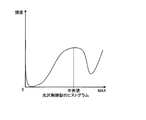
図11は前述の光沢度目標値テーブル5114について概念的に例示する図である。例示した図ではどのCMYK値の総量に対しても光沢度目標値は常に一定の光沢度となっている。ただし、光沢度目標値テーブル5114は、この例に限定されるものではない。例えば、低濃度部や高濃度部については目標値が中濃度部と比較して高めに設定されるように光沢度目標値テーブル5114を構成してもよい。 FIG. 11 is a diagram conceptually illustrating the glossiness target value table 5114 described above. In the illustrated example, the glossiness target value is always a constant glossiness for any total amount of CMYK values. However, the glossiness target value table 5114 is not limited to this example. For example, the glossiness target value table 5114 may be configured so that the target value is set higher for the low density part and the high density part than the medium density part.
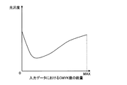
有色色材量対光沢度テーブル5116は、有色色材の総量に対する光沢度を定めたテーブルデータである。図12は、有色色材量対光沢度テーブル5116の一例を概念的に示す図である。図12の例では、有色色材量対光沢度テーブル5116は、一般的な「有色色材総量の少ない部分と多い部分の光沢度が高く、中間色の光沢度が低くなる」という特徴を有するテーブルとなっている。ただし、有色色材量対光沢度テーブル5116はこれに限定されるものではない。例えば、「有色色材総量が少ないほど光沢度が高く、有色色材総量が多くなるほど光沢度が低くなる」ように有色色材量対光沢度テーブル5116を構成することもできる。 The colored color material amount versus glossiness table 5116 is table data that defines the glossiness with respect to the total amount of colored color materials. FIG. 12 is a diagram conceptually illustrating an example of the color material amount versus glossiness table 5116. In the example of FIG. 12, the color material amount versus glossiness table 5116 has a general characteristic that “the glossiness of the portion with a small amount of the color material and the portion with a large amount is high and the glossiness of the intermediate color is low”. It has become. However, the color material amount versus glossiness table 5116 is not limited to this. For example, the color material amount / gloss degree table 5116 may be configured so that “the smaller the total amount of colored color material, the higher the glossiness, and the higher the total amount of colored color material, the lower the glossiness”.
色分解量決定部5115は、印刷対象とする画像データである有色版データ5111の各画素において、有色色材量対光沢度テーブル5116を参照して、CMYK値の総量に対する光沢度を取得する。そして、色分解量決定部5115は、有色色材量対光沢度テーブル5116から取得した光沢度と光沢度目標値決定部5113で決定された光沢度目標値との差を求め、当該差に基づいて、光沢度の不均一性がどの程度発生しているかを判断し、色分解処理をどの程度実施すべきか、すなわち色分解量を決定する。この色分解量の決定について、以下のように行われる。
The color separation
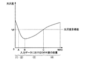
図13Aは、実施形態1の光沢度の不均一性の補正について概念的に例示する図である。図13Aでは光沢度目標値の値をTgt、Tgtと有色色材量対光沢度テーブル5116のグラフとの交点となる2箇所の点において、その際の入力データにおけるCMYK総量値をA及びC、光沢度が最少となる箇所のCMYK総量値をB、CMYK総量値の最小値を0、最大値をMaxとしている。ここで、総量値の各区間において光沢度Tgtを光沢度目標値として、CMY値とK値の間における色置換を実施する。 FIG. 13A is a diagram conceptually illustrating correction of nonuniformity in glossiness according to the first embodiment. In FIG. 13A, the gloss target value is Tgt, and the CMYK total amount values in the input data at the two points that are the intersections of Tgt and the graph of the color material amount vs. glossiness table 5116 are A and C. The CMYK total amount value of the portion where the glossiness is minimum is B, the minimum value of the CMYK total amount value is 0, and the maximum value is Max. Here, color replacement between the CMY value and the K value is performed with the glossiness Tgt as the glossiness target value in each section of the total value.
総量値の区間0〜Aにおいては、CMYK総量値がAに近づくようにKをCMYに置き換え、総量値を増やすことで光沢度Tgtの実現を目指す。総量値の区間A〜Bにおいては、総量値がAに近づくようにCMYをKに置き換え、総量値を減らすことで光沢度Tgtの実現を目指す。総量値の区間B〜Cにおいては、CMYK総量値がCに近づくようにKをCMYに置き換え、総量値を増やすことで光沢度Tgtの実現を目指す。総量値の区間C〜Maxにおいては、総量値がCに近づくようにCMYをKに置き換え、総量値を減らすことで光沢度Tgtの実現を目指す。
In
図13Bは、実施形態1の色分解処理前の光沢度、色分解処理後の光沢度、光沢度目標値を示す図である。図13Bに示すように、色分解処理後の光沢度が、色分解処理前の光沢度に比べて光沢度目標値に近づいている。 FIG. 13B is a diagram illustrating a glossiness before color separation processing, a glossiness after color separation processing, and a glossiness target value according to the first embodiment. As shown in FIG. 13B, the glossiness after the color separation processing is closer to the glossiness target value than the glossiness before the color separation processing.
図14は、この際のCMY値とK値の間における色分解処理について概念的に例示する図である。例示した図に示されるように、色分解処理部5117は、C,M,Y3色の重なりからなる成分を減らしてKで置換するという一般的な下色除去アルゴリズム、すなわちUCR(Under Color Removal)アルゴリズムを用いて、色分解量決定部5115で決定された色分解量で色置換を行っている。ただし、これに限定されるものではなく、例えば、GCR(Grey Component Replacement)アルゴリズムや独自のアルゴリズムを使用して、CMY値とK値の間における色置換を実施するように色分解処理部5117を構成してもよい。
FIG. 14 is a diagram conceptually illustrating color separation processing between CMY values and K values at this time. As shown in the illustrated diagram, the color
このようにして、最終的には色分解処理部5117によってCMY値とK値の間を調整することで、光沢度が調整される。その結果、有色版データ’5121が版調整部511の出力として得られる。なお、本実施形態においては光沢制御版データの調整は実施されず、結果として入力データと同じものが光沢制御版データ5122として版調整部511の出力として得られる。
In this way, the glossiness is adjusted by finally adjusting between the CMY value and the K value by the color
なお、最終的に出力として得られた有色版データ及び光沢制御版データの色材量の総和において、後段のエンジンが規定する総量を超えるようなことがあれば、一般的な総量規制処理を用いて色材の総量を一定値内に規制するような処理を実施しても良い。 If the total amount of color material in the color plate data and gloss control plane data finally obtained as output exceeds the total amount specified by the subsequent engine, use the general total amount restriction process. Thus, a process for regulating the total amount of the color material within a certain value may be performed.
クリアプロセッシング56には、レンダリングエンジン51が変換した8ビットの光沢制御版データがsi1部52を介して入力されると共に、TRC53がガンマ補正を行ったCMYKの各8ビットの有色版データがsi2部54を介して入力される。
The
クリアプロセッシング56には、後述する表面効果選択テーブルが記憶される。クリアプロセッシング56は、si1部52から入力された8ビットの光沢制御版データが記憶される。
The
クリアプロセッシング56は、si1部52から入力され、光沢制御版データを用いて、後述の表面効果選択テーブルを参照して、光沢制御版データを構成する各画素の表す濃度値(画素値)に対する表面効果を判断する。そして、クリアプロセッシング56は、当該判断に応じて、グロッサ80のオン又はオフを決定すると共に、入力されたCMYKの各8ビットの有色版データを用いてインバースマスクやベタマスクを適宜生成することにより、クリアトナーを付着させるための2ビットのクリアトナー版データを適宜生成する。そして、クリアプロセッシング56は、表面効果の判断の結果に応じて、プリンタ機70で用いるクリアトナー版データと、低温定着機90で用いるクリアトナー版データとを適宜生成してこれらを出力すると共に、グロッサ80のオン又はオフを示すオンオフ情報を出力する。
The
ここで、インバースマスクとは、表面効果を与える対象の領域を構成する各画素上のCMYKのトナー及びクリアトナーを合わせた総付着量が均一になるようにするためのものである。具体的には、CMYK版の画像データにおいて当該対象の領域を構成する画素の表す濃度値を全て加算し、その加算値を所定値から差し引いた画像データがインバースマスクとなる。例えば、上述のインバースマスク1は以下の式1で表される。
Here, the inverse mask is for uniformizing the total adhesion amount of the CMYK toner and the clear toner on each pixel constituting the region to which the surface effect is applied. Specifically, image data obtained by adding all density values represented by pixels constituting the target area in the CMYK version image data and subtracting the added value from a predetermined value is an inverse mask. For example, the above-described
Clr=100−(C+M+Y+K) 但し、Clr<0となる場合、Clr=0
・・・(式1)
Clr = 100− (C + M + Y + K) However, when Clr <0, Clr = 0
... (Formula 1)
式1において、Clr,C,M,Y,Kは、クリアトナー及びC,M,Y,Kの各トナーのそれぞれについて、各画素における濃度値から換算される濃度率を表すものである。即ち、式1によって、C,M,Y,Kの各トナーの総付着量にクリアトナーの付着量を加えた総付着量を、表面効果を与える対象の領域を構成する全ての画素について100%にする。なお、C,M,Y,Kの各トナーの総付着量が100%以上である場合には、クリアトナーは付着させずに、その濃度率は0%にする。これは、C,M,Y,Kの各トナーの総付着量が100%を超えている部分は定着処理により平滑化されるためである。このように、表面効果を与える対象の領域を構成する全ての画素上の総付着量を100%以上にすることで、当該対象の領域においてトナーの総付着量の差による表面の凸凹がなくなり、この結果、光の正反射による光沢が生じるのである。但し、インバースマスクには、式1以外により求められるものがあり、インバースマスクの種類は複数有り得る。
In
例えば、インバースマスクは、各画素にクリアトナーを均一に付着させるものであってもよい。この場合のインバースマスクは、ベタマスクともいい、以下の式2で表される。
Clr=100・・・(式2)
For example, the inverse mask may be one in which clear toner is uniformly attached to each pixel. The inverse mask in this case is also referred to as a solid mask, and is represented by the following
Clr = 100 (Formula 2)
尚、表面効果を与える対象の画素の中でも、100%以外の濃度率が対応付けられるものがあるようにしても良く、ベタマスクのパターンは複数有り得る。 Note that among the pixels to which the surface effect is applied, there may be a pixel associated with a density ratio other than 100%, and there may be a plurality of solid mask patterns.
また、例えばインバースマスクは、各色の地肌露出率の乗算により求められるものであってもよい。この場合のインバースマスクは、例えば以下の式3で表される。
Clr=100×{(100−C)/100}×{(100−M)/100}×{(100−Y)/100}×{(100−K)/100}・・・(式3)
上記式3において、(100−C)/100は、Cの地肌露出率を示し、(100−M)/100は、Mの地肌露出率を示し、(100−Y)/100は、Yの地肌露出率を示し、(100−K)/100はKの地肌露出率を示す。
For example, the inverse mask may be obtained by multiplying the background exposure rate of each color. The inverse mask in this case is expressed by the following
Clr = 100 × {(100−C) / 100} × {(100−M) / 100} × {(100−Y) / 100} × {(100−K) / 100} (Equation 3)
In the
また、例えばインバースマスクは、最大面積率の網点が平滑性を律すると仮定した方法により求められるものであってもよい。この場合のインバースマスクは、例えば以下の式4で表される。
Clr=100−max(C,M,Y,K)・・・(式4)
上記式4において、max(C,M,Y,K)は、CMYKのうち最大の濃度値を示す色の濃度値が代表値となることを示す。
Further, for example, the inverse mask may be obtained by a method that assumes that the halftone dot of the maximum area ratio regulates smoothness. The inverse mask in this case is expressed by the following
Clr = 100−max (C, M, Y, K) (Formula 4)
In the
要するに、インバースマスクは、上記式1〜式4の何れかの式により表されるものであればよい。
In short, the inverse mask only needs to be expressed by any one of the
次に、表面効果選択テーブルについて説明する。表面効果選択テーブルは、表面効果を示す光沢制御値である濃度値と当該表面効果の種類の対応関係を示すと共に、これらと、画像形成システムの構成に応じた後処理機に関する制御情報と、プリンタ機70で用いるクリアトナー版データ及び後処理機で用いるクリアトナー版データとの対応関係を示すテーブルである。
Next, the surface effect selection table will be described. The surface effect selection table shows a correspondence relationship between the density value, which is a gloss control value indicating the surface effect, and the type of the surface effect, and control information regarding the post-processing device according to the configuration of the image forming system, a
画像形成システムの構成は、様々に異なり得るが、本実施の形態においては、プリンタ機70に後処理機としてグロッサ80及び低温定着機90が接続される構成である。このため、画像形成システムの構成に応じた後処理機に関する制御情報とは、グロッサ80のオン又はオフを示すオンオフ情報となる。また、後処理機で用いるクリアトナー版データとしては、低温定着機90で用いるクリアトナー版データがある。
Although the configuration of the image forming system may be variously different, in the present embodiment, the
図15は、表面効果選択テーブルのデータ構成を例示する図である。尚、表面効果選択テーブルは、異なる画像形成システムの構成毎に、後処理機に関する制御情報と、プリンタ機70で用いるクリアトナー版1の画像データ及び後処理機で用いるクリアトナー版2の画像データと、濃度値及び表面効果の種類との対応関係を示すように構成され得るが、図15では、本実施の形態に係る画像形成システムの構成に応じたデータ構成を例示している。同図に示される表面効果の種類及び濃度値の対応関係においては、濃度値の範囲毎に表面効果の各種類が対応付けられている。また、その濃度値の範囲の代表となる値(代表値)から換算される濃度の割合(濃度率)に対して2%単位で表面効果の各種類が対応付けられている。具体的には、濃度率が84%以上となる濃度値の範囲(「212」〜「255」)に対して光沢を与える表面効果(鏡面効果及びベタ効果)が対応付けられており、濃度率が16%以下となる濃度値の範囲(「1」〜「43」)に対して光沢を抑える表面効果(網点マット及びつや消し)が対応付けられている。また、濃度率が20%〜80%となる濃度値の範囲には、テクスチャや地紋透かしなどの表面効果が対応付けられている。
FIG. 15 is a diagram illustrating a data configuration of the surface effect selection table. Note that the surface effect selection table includes control information regarding the post-processing device, image data of the
図15の表面効果選択テーブルを例にあげてより具体的に説明すると、例えば、「238」〜「255」の画素値に対しては表面効果として鏡面光沢(PM:Premium Gross)が対応付けられており、このうち、「238」〜「242」の画素値、「243」〜「247」の画素値及び「248」〜「255」の画素値の3つの範囲に対して各々異なるタイプの鏡面光沢が対応付けられている。 More specifically, taking the surface effect selection table of FIG. 15 as an example, for example, specular gloss (PM: Premium Gross) is associated with the pixel values “238” to “255” as the surface effect. Among these, different types of specular surfaces for three ranges of pixel values “238” to “242”, pixel values “243” to “247”, and pixel values “248” to “255”, respectively. Gloss is associated.
また、「212」〜「232」の画素値に対しては、ベタ光沢(G:Gross)が対応付けられており、このうち、「212」〜「216」の画素値、「217」〜「221」の画素値、「222」〜「227」の画素値及び「228」〜「232」の画素値の4つの範囲に対して各々異なるタイプのベタ光沢が対応付けられている。
Further, the pixel values “212” to “232” are associated with solid gloss (G: Gross), and among these, the pixel values “212” to “216”, “217” to “232”. Different types of solid glossiness are associated with the four ranges of the
また、「23」〜「43」の画素値に対しては、網点マット(M:Matt)が対応付けられており、このうち、「23」〜「28」の画素値、「29」〜「33」の画素値、「34」〜「38」の画素値及び「39」〜「43」の画素値の4つの範囲に対して各々異なるタイプの網点マットが対応付けられている。また、「1」〜「17」の画素値に対しては、つや消し(PM:Premium Matt)が対応付けられており、このうち、「1」〜「7」の画素値、「8」〜「12」の画素値及び「13」〜「17」の画素値の3つの範囲に対して各々異なるタイプのつや消しが対応付けられている。これらの同一の表面効果の異なるタイプはプリンタ機70や低温定着機90で使用するクリアトナー版データを求める式に違いがあり、プリンタ本体や後処理機の動作は同じである。尚、「0」の濃度値には、表面効果を与えないことが対応付けられている。
The pixel values “23” to “43” are associated with halftone dot mats (M: Matt), and among these, the pixel values “23” to “28”, “29” to “29” Different types of halftone mats are associated with the four ranges of “33” pixel values, “34” to “38” pixel values, and “39” to “43” pixel values. Further, the pixel values of “1” to “17” are associated with matte (PM), among which pixel values of “1” to “7” and “8” to “7”. Different types of matte are associated with the three ranges of the pixel value of “12” and the pixel values of “13” to “17”. These different types of the same surface effect have different formulas for obtaining the clear toner plane data used in the
また、図15には、画素値及び表面効果に対応して、グロッサ80のオン又はオフを示すオンオフ情報と、プリンタ機70で用いるクリアトナー版1の画像データ(図1のClr−1)及び低温定着機90で用いるクリアトナー版2の画像データの内容とが各々示されている。例えば、表面効果が鏡面光沢である場合、グロッサ80をオンにすることが示されると共に、プリンタ機70で用いるクリアトナー版1の画像データは、インバースマスクを表すものであり、低温定着機90で用いるクリアトナー版2の画像データ(図1のClr−2)は、ないことが示されている。当該インバースマスクは、例えば上述した式1により求められるものである。尚、図15に示される例は、表面効果として鏡面効果が指定された領域が、画像データによって規定される領域全体に相当する場合の例である。表面効果として鏡面効果が指定された領域が、画像データによって規定される領域の一部に相当する場合の例については後述する。
FIG. 15 also shows on / off information indicating whether the
また、濃度値が「228」〜「232」であり表面効果がベタ光沢である場合、グロッサ80をオフにすることが示されていると共に、プリンタ機70で用いるクリアトナー版1の画像データは、インバースマスク1であり、低温定着機90で用いるクリアトナー版2の画像データは、ないことが示されている。
Further, when the density value is “228” to “232” and the surface effect is solid gloss, it is indicated that the
尚、当該インバースマスク1は、上記式1〜式4の何れかの式により表されるものであればよい。これはグロッサ80がオフなので平滑化されるトナーの総付着量が異なるため、鏡面光沢により表面の凹凸が増え、その結果、鏡面光沢により光沢度が低いベタ光沢が得られる。また、表面効果が網点マットである場合、グロッサ80をオフにすることが示されていると共に、プリンタ機70で用いるクリアトナー版1の画像データは、ハーフトーン(網点)を表すものであり、低温定着機90で用いるクリアトナー版2の画像データは、ないことが示されている。また、表面効果がつや消しである場合、グロッサ80をオン又はオフのいずれにしても良いことが示されていると共に、プリンタ機70で用いるクリアトナー版1の画像データは、なく、低温定着機90で用いるクリアトナー版2の画像データは、ベタマスクを表すものであることが示されている。当該ベタマスクは、例えば上述の式2により求められるものである。
The
クリアプロセッシング56は、上述のように、表面効果選択テーブルを参照して、光沢制御版データによって示される各画素値に対応付けられている表面効果を判断すると共に、グロッサ80のオン又はオフを判断して、プリンタ機70及び低温定着機90でどのようなクリアトナー版データを用いるかを判断する。尚、クリアプロセッシング56は、グロッサ80のオン又はオフの判断を1ページ毎に行う。そして、上述したように、クリアプロセッシング56は、当該判断の結果に応じて、クリアトナー版データを適宜生成してこれを出力すると共に、グロッサ80に対するオンオフ情報を出力する。これにより、用紙の種類に応じてユーザが意図した効果の光沢効果を有するクリアトナー版データを生成することになる。
As described above, the
si3部57は、ハーフトーン処理後のCMYKの各2ビットの画像データと、クリアプロセッシング56が生成した2ビットのクリアトナー版データとを統合し、統合した画像データをMIC60に出力する。尚、クリアプロセッシング56は、プリンタ機70で用いるクリアトナー版データ及び低温定着機90で用いるクリアトナー版データのうち少なくとも一方を生成しない場合があるので、クリアプロセッシング56が生成した方のクリアトナー版データがsi3部57で統合され、両方のクリアトナー版データをクリアプロセッシング56が生成していない場合には、si3部57からはCMYKの各2ビットの画像データが統合された画像データが出力される。この結果、DFE50からは各々2ビットの4つ〜6つの画像データがMIC60へ送り出されることになる。また、si3部57は、クリアプロセッシング56が出力したグロッサ80に対するオンオフ情報もMIC60に出力する。
The
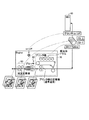
MIC60は、DFE50とプリンタ機70とに接続される。MIC60は、後処理機として搭載されている装置構成を示す装置構成情報をDFE50に出力する。また、MIC60は、有色版データ、クリアトナー版データをDFE50から受信して各画像データを対応する装置に振り分けるとともに、後処理機の制御を行う。より具体的には、MIC60は、図16に例示されるように、DFE50から出力された画像データのうちCMYKの有色版データをプリンタ機70に出力し、プリンタ機70で用いるクリアトナー版データがある場合にはこれもプリンタ機70に出力し、DFE50から出力されたオンオフ情報を用いて、グロッサ80をオン又はオフにして、低温定着機90で用いるクリアトナー版データがある場合にはこれを低温定着機90に出力する。グロッサ80はオンオフ情報によって定着を行う経路と行わない経路とを切り替えても良い。低温定着機90はクリアトナー版データの有無によってオン又はオフの切り替えやグロッサ80と同様の経路の切り替えをしても良い。
The
また、図16に示すように、プリンタ機70、グロッサ80、低温定着機90からなる印刷装置30は、記録媒体を搬送する搬送路を備えている。なお、プリンタ機70は、詳細には、電子写真方式の複数の感光体ドラム、感光体ドラム上に形成されたトナー像を転写される転写ベルト、転写ベルト上のトナー像を記録媒体に転写する転写装置、及び記録媒体上のトナー像を該記録媒体に定着させる定着機を備える。記録媒体は、図示を省略する搬送部材によって搬送路を搬送されることで、プリンタ機70、グロッサ80、低温定着機90の設けられている位置を、この順に搬送される。そして、これらの機器によって順次処理が行われて画像形成及び表面効果が付与された後に、図示を省略する搬送機構によって搬送路を搬送されて、印刷装置の外部へと排出される。
As shown in FIG. 16, the
このため、DFE50から出力された画像データが、CMYKの有色版データ及びクリアトナー版データを含む場合には、該有色版データによって特定される有色画像が記録媒体に有色トナーで形成されると共に、クリアトナー版データによって特定される種類の表面効果がクリアトナーで該記録媒体に付与され、クリアトナー版データによって特定される透明画像がクリアトナーで該記録媒体に形成される。すなわち、記録媒体には、用紙の種類に応じてユーザが意図した効果の光沢効果を有するクリアトナー版データに基づいた表面効果が、記録媒体に付与されることとなる。
Therefore, when the image data output from the
次に、本実施の形態に係る画像形成システムが行う光沢制御処理の手順について図17を用いて説明する。DFE50がホスト装置10から印刷データを受信すると(ステップS11)、レンダリングエンジン51は、これを言語解釈して、ベクタ形式で表現される画像データをラスタ形式に変換すると共に、RGB形式で表現された色空間をCMYK形式の色空間に変換して、CMYKの各8ビットの有色版データ及び8ビットの光沢制御版データを得る(ステップS12)。
Next, a gloss control process performed by the image forming system according to the present embodiment will be described with reference to FIG. When the
この光沢制御版データの変換処理では、図4の光沢制御版データ、すなわち、図7で示したような、描画オブジェクトごとに表面効果を特定する濃度値が指定された光沢制御版データを、描画オブジェクトを構成する画素ごとに濃度値が指定された光沢制御版データに変換する。 In this gloss control plane data conversion process, the gloss control plane data shown in FIG. 4, that is, the gloss control plane data in which the density value specifying the surface effect for each drawing object is designated as shown in FIG. It is converted into gloss control plane data in which a density value is designated for each pixel constituting the object.
すなわち、レンダリングエンジン51は、図7で示される光沢制御版データの描画オブジェクトに対応する座標の範囲の画素に対して、描画オブジェクトに対して設定された濃度値を付与することにより、光沢制御版データを変換する。これにより、光沢制御版データは、画素ごとに表面効果が設定された光沢制御版データに変換されることになる。
That is, the
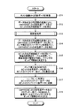
8ビット光沢制御版データが出力されたら、版調整部511により版調整処理を行う(ステップS13)。図18は、実施の形態1にかかる版調整処理の手順を示すフローチャートである。
When the 8-bit gloss control plane data is output, the
まず、光沢度目標値決定部5113は、光沢度目標値テーブル5114を参照して、各CMYKの総量値における光沢度目標値を決定する(ステップS31)。
First, the glossiness target
次に、印刷対象とする画像データである有色版データ5111の各画素に対して、以下のステップS32、S33の処理が実行される。ステップS32では、色分解量決定部5115が、有色色材量対光沢度テーブル5116を参照して、上述したように、光沢度目標値を満たすための色分解量を決定する(ステップS32)。そして、色分解量決定部5115は、決定された色分解量に基づいて色分解処理を行う(ステップS33)。
Next, the following processes in steps S32 and S33 are performed on each pixel of the
図17に戻り、色分解処理が行われたら、DFE50のTRC53は、CMYKの各8ビットの有色版データに対してキャリブレーションにより生成された1D_LUTのガンマカーブでガンマ補正を行い、ガンマ補正後のCMYKの各8ビットの有色版データをsi2部54を介してハーフトーンエンジン55とクリアプロセッシング56とに出力する。ハーフトーンエンジン55はガンマ補正後の画像データに対して、プリンタ機70に出力するためのCMYK各2ビットの有色版データのデータ形式に変換するハーフトーン処理を行い、ハーフトーン処理後のCMYKの各2ビットの有色版データを得る(ステップS14)。
Returning to FIG. 17, when the color separation processing is performed, the
次に、クリアプロセッシング56は、8ビットの光沢制御版データを用いて、ステップS14で選択された、用紙種類に対応する表面効果選択テーブルを参照して、光沢制御版データによって示される各画素値に対して指定された表面効果を判断する。そして、クリアプロセッシング56は、光沢制御版データを構成する全ての画素について、このような判断を行う。尚、光沢制御版データにおいては、各表面効果を与える領域を構成する全ての画素について基本的に同一の範囲の濃度値を表す。このため、同一の表面効果であると判断した近傍の画素については、クリアプロセッシング56は、同一の表面効果を与える領域に含まれるものとして判断する。このようにして、クリアプロセッシング56は、表面効果を与える領域と、当該領域に対して与える表面効果の種類とを判断する。そして、クリアプロセッシング56は、当該判断に応じて、グロッサ80のオン又はオフを決定する(ステップS15)。
Next, the
次に、クリアプロセッシング56は、si2部54から出力されるガンマ補正後のCMYKの各8ビットの有色版データを適宜用いて、クリアトナーを付着させるための8ビットのクリアトナー版データを適宜生成する(ステップS16)。そして、ハーフトーンエンジン55は、ハーフトーン処理により、8ビットの画像データを用いた8ビットのクリアトナー版データを2ビットのクリアトナー版データに変換する(ステップS17)。
Next, the
次に、DFE50のSi3部57は、ステップS13で得たハーフトーン処理後のCMYKの各2ビットの有色版データと、ステップS17で生成した2ビットのクリアトナー版データとを統合し、統合した画像データと、ステップS15で決定したグロッサ80のオン又はオフを示すオンオフ情報とをMIC60に対して出力する(ステップS18)。
Next, the
尚、ステップS16で、クリアプロセッシング56が、クリアトナー版データを生成していない場合には、ステップS18では、ステップS13で得たハーフトーン処理後のCMYKの各2ビットの有色版データのみが統合されてMIC60に出力される。
If the
このように本実施の形態では、光沢度の不均一性に対し、狙いとする光沢度に対して乖離する部分においてクリアの色材を調整せずとも有色色材側の量を調整することで、全面の光沢度差を解消して印刷品質を向上させることができる。 As described above, in the present embodiment, by adjusting the amount on the colored color material side without adjusting the clear color material in the portion deviating from the target glossiness, with respect to the uneven glossiness. In addition, it is possible to improve the printing quality by eliminating the gloss difference on the entire surface.
(実施の形態2)
実施の形態1では、光沢度目標値は用紙によらず統一して定められていたが、この実施の形態2では、用紙の種類に応じて光沢度目標値を定めて色分解処理が行われる。実施の形態2における印刷システムの構成、DFE50、MIC60、印刷装置30の機能および構成、および処理の流れについては、実施形態1と共通で重複する部分については説明を省略する。
(Embodiment 2)
In the first embodiment, the glossiness target value is determined uniformly regardless of the paper, but in this second embodiment, the color separation processing is performed by determining the glossiness target value according to the type of paper. . Regarding the configuration of the printing system, the functions and configurations of the
図19は、実施の形態2の用紙に応じた光沢度目標値を定めた光沢度目標値テーブルを例示する図である。図19は、図10内の光沢度目標値テーブル5114に相当し、CMYK値の総量に対する光沢度目標値を定めた光沢度目標値テーブルを、用紙毎に定義したものである。なお、本実施形態では、3種類の用紙についての目標値テーブルについて例示しているが、用紙種類は3つに限定しなくても良い。 FIG. 19 is a diagram exemplifying a glossiness target value table in which glossiness target values corresponding to the sheets of the second embodiment are defined. FIG. 19 corresponds to the glossiness target value table 5114 in FIG. 10, and defines a glossiness target value table that defines glossiness target values for the total amount of CMYK values for each sheet. In the present embodiment, the target value table for three types of paper is illustrated, but the number of paper types is not limited to three.
本実施の形態では、DFE50の版調整部511が、ホスト装置10から、印刷する用紙の種類を受信する。そして、版調整部511の光沢度目標値決定部5113が、図18のステップS31で、受信した用紙の種類に対応する光沢度目標値を、光沢度目標値テーブル5114から読み出して決定する。色分解量の決定(図18のステップS32)および色分解処理(色の置換処理、S33の処理)については実施の形態1と同様である。
In the present embodiment, the
このように本実施の形態によれば、用紙の種類に応じて個別の光沢度目標値を光沢度目標値テーブル5114に定めておき、版調整部511が、光沢度目標値テーブル5114から、印刷する用紙の種類に応じて光沢度目標値を決定して、色分解処理を行っているので、用紙の種類に応じて最適な光沢度目標値を指定して、印刷品質をより向上させることができる。
As described above, according to the present embodiment, individual glossiness target values are determined in the glossiness target value table 5114 according to the type of paper, and the
(実施の形態3)
実施の形態3は、光沢制御版データに基づいて、光沢度目標値を決定している。実施の形態3における印刷システムの構成、DFE50、MIC60、印刷装置30の機能および構成、および処理の流れについては、実施形態1と共通で重複する部分については説明を省略する。
(Embodiment 3)
In the third embodiment, the gloss target value is determined based on the gloss control plane data. Regarding the configuration of the printing system, the functions and configurations of the
本実施の形態のDFE50の版調整部511における光沢度目標値決定部5113は、光沢制御版データに基づいて、光沢度目標値を決定する。より具体的には、光沢度目標値決定部5113は、光沢制御版データの光沢度のヒストグラムを用いて光沢度目標値を決定する。
The glossiness target
図20は、実施の形態3の光沢制御版データのヒストグラムから光沢度目標値を算出する方法を例示する図である。光沢度目標値決定部5113は、光沢制御版データにおける各画素の光沢度から、光沢度の目標値を、統計的に算出する。図20の例では、光沢度目標値決定部5113は、光沢制御版データの光沢度のヒストグラムを用いてその中央値を光沢度目標値として算出している。
FIG. 20 is a diagram illustrating a method for calculating a glossiness target value from a histogram of gloss control plane data according to the third embodiment. The glossiness target
ただし、これに限定されるものではなく、光沢制御版データのヒストグラムの平均値等の統計データを用いて光沢度目標値を決定するように光沢度目標値決定部5113を構成することができる。
However, the present invention is not limited to this, and the glossiness target
また、光沢制御版データに基づいて光沢度目標値を決定するものであれば、ヒストグラムを用いることに限定されるものではない。例えば、光沢制御版データの構成情報と規定のパターンとの比較やマッチング処理で判定し、その結果で規定の光沢度目標値を決定するように光沢度目標値決定部5113を構成することもできる。
Further, as long as the glossiness target value is determined based on the gloss control plane data, it is not limited to using the histogram. For example, the glossiness target
色分解量の決定および色分解処理(色の置換処理)については実施の形態1と同様である。 The determination of the color separation amount and the color separation processing (color replacement processing) are the same as those in the first embodiment.
このように本実施の形態によれば、光沢制御版データに基づいて光沢度目標値を決定しているので、最適な光沢度目標値を指定することができ、これにより、印刷品質をより向上させることができる。 As described above, according to the present embodiment, since the gloss target value is determined based on the gloss control plane data, it is possible to specify the optimum gloss target value, thereby further improving the print quality. Can be made.
(実施の形態4)
実施の形態4は、ユーザの指定により光沢度目標値が決定されるものである。実施の形態3における印刷システムの構成、DFE50、MIC60、印刷装置30の機能および構成、および処理の流れについては、実施形態1と共通で重複する部分については説明を省略する。
(Embodiment 4)
In the fourth embodiment, the glossiness target value is determined by user designation. Regarding the configuration of the printing system, the functions and configurations of the
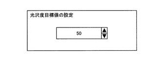
本実施の形態のDFE50の版調整部511における光沢度目標値決定部5113は、表示部59に、光沢度目標値の設定画面を表示する。図21は、実施の形態4にかかる光沢度目標値の設定画面の一例を示す図である。ユーザは、かかる光沢度目標値の設定画面から所望の光沢度目標値を入力する。光沢度目標値決定部5113は、光沢度目標値の設定画面からユーザにより入力された値を光沢度目標値として決定する。色分解量の決定および色分解処理(色の置換処理)については実施の形態1と同様である。
The glossiness target
なお、図21の例では、光沢度目標値を直接指定する方法について例示しているが、予め何通りかの選択肢を用意しておき、それらの選択肢の中から目標値を指定するように光沢度目標値決定部5113を構成したり、図20のような統計情報を参照しながら指定できるように光沢度目標値決定部5113を構成してもよい。
In the example of FIG. 21, a method of directly specifying the gloss target value is illustrated, but several options are prepared in advance, and the gloss value is specified so that the target value is specified from these options. The gloss target
このように本実施の形態によれば、ユーザに目標値を直接指定させる手段を提供することで、最適な光沢度の目標値を指定することができ、印刷品質をより向上させることができる。 As described above, according to the present embodiment, by providing means for allowing the user to directly specify the target value, the target value of the optimum glossiness can be specified, and the print quality can be further improved.
(実施の形態5)
実施の形態5では、DFE50は、光沢制御版データに基づいて特定の表面効果が付与される領域を抽出し、抽出された領域に対して色分解処理を行っている。実施の形態5における印刷システムの構成、DFE50、MIC60、印刷装置30の機能および構成、および処理の流れについては、実施形態1と共通で重複する部分については説明を省略する。
(Embodiment 5)
In the fifth embodiment, the
図22は、実施の形態5にかかる版調整部22511の機能的構成を主として示したブロック図である。版調整部22511は、図22に示すように、光沢度目標値テーブル5114と、色分解量決定部5115と、有色色材量対光沢度テーブル5116と、色分解処理部5117と、表面効果領域抽出部5131と、表面効果選択テーブル5132とを主に備えている。ここで、光沢度目標値決定部5113、光沢度目標値テーブル5114、有色色材量対光沢度テーブル5116の機能および構成は、実施の形態1と同様である。表面効果選択テーブル5132は、実施の形態1で図15を用いて説明したものと同様であり、用紙に付与する表面効果の種類と表面効果を付与する用紙における領域とを特定したテーブルである。
FIG. 22 is a block diagram mainly illustrating a functional configuration of the
図22に示すように、実施の形態1と同様に、有色版データ5111が光沢度目標値決定部5113への入力となるとともに、光沢制御版データ5112(8bitx1plane)が表面効果領域抽出部5131への入力となる。表面効果領域抽出部5131は、光沢制御版データ5112に基づいて、光沢制御版データ5112から特定の表面効果が付与される領域を抽出する。色分解量決定部5115は、表面効果領域抽出部5131によって抽出された領域に対して、各有色材の色分解量を決定する。色分解処理部5117は、表面効果領域抽出部5131によって抽出された領域に対して、色分解量決定部5115によって決定された色分解量に基づいて色の置換を実行する。
As shown in FIG. 22, the
図23は、実施の形態5にかかる版調整処理の手順を示すフローチャートである。図24は、実施の形態5にかかる版調整処理について説明するための図である。まず、実施の形態1と同様に、光沢度目標値決定部5113は、光沢度目標値テーブル5114を参照して、各CMYKの総量値における光沢度目標値を決定する(ステップS31)。
FIG. 23 is a flowchart of a procedure of plate adjustment processing according to the fifth embodiment. FIG. 24 is a diagram for explaining plate adjustment processing according to the fifth embodiment. First, similarly to the first embodiment, the glossiness target
次に、表面効果領域抽出部5131は、光沢制御版データ5112に基づいて、光沢制御版データ5112から特定の表面効果が付与される領域、すなわち色分解処理の実施対象とする領域を抽出する(ステップS52)。具体的には、表面効果領域抽出部5131は、表面効果選択テーブル5132に規定された対象光沢効果の情報を元に、対象とする表面効果の領域のみを抽出する。
Next, based on the gloss
例えば、高光沢部の光沢度を安定化したいというケースを想定すると、表面効果選択テーブル5132の光沢の有無に関する表面効果の種類を参考にすると、対象の表面効果としてはG(ベタ光沢)及びPG(鏡面光沢)の表面効果に関する領域のみ対象とすれば良いと判断することができる。図24に示すように、表面効果領域抽出部5131が、G及びPGの表面効果に関する領域のみを抽出した場合について例示している。図24では、表面効果領域抽出部5131は、光沢制御版データ5112を入力として、G及びPGの表面効果のみを抽出した領域5133を出力としている。
For example, assuming a case where it is desired to stabilize the glossiness of a high-gloss portion, referring to the type of surface effect relating to the presence or absence of glossiness in the surface effect selection table 5132, the target surface effects are G (solid gloss) and PG. It can be determined that only the region relating to the surface effect of (specular gloss) needs to be targeted. As shown in FIG. 24, the case where the surface effect
なお、図24の例では、G及びPGの表面効果に関する複数の表面効果についての領域のみを抽出した場合について例示したが、これに限定されるものではなく、M(網点マット)やPM(つや消し)等の他の表面効果の領域を抽出するように表面効果領域抽出部5131を構成することができる。また、抽出する対象の表面効果の数として単一の表面効果のみを指定するよう表面効果領域抽出部5131を構成しても良い。
In the example of FIG. 24, the case of extracting only the regions for a plurality of surface effects related to the surface effects of G and PG is illustrated, but the present invention is not limited to this, and M (halftone mat) or PM ( The surface effect
このようにして得られた領域情報は、色分解量決定部5115へ入力される。色分解量決定部5115では、当領域情報に対してのみ色分解処理の実施対象とすることを条件として考慮する。そして、その後の色分解処理部5117にて色分解処理が実施され、有色色材の量が調整される。具体的なステップS32の色分解量の決定処理、およびステップS33の色分解処理(色の置換処理)については実施の形態1と同様である。
The area information obtained in this way is input to the color separation
このように本実施の形態では、色分解処理を表面効果選択テーブル5132内の任意の表面効果に該当する領域に対してのみ実行しているので、最適な領域に対してのみ光沢度調整を実施することができる。また、本実施形態によれば、対象とする処理領域を限定することで不要な色分解処理を回避することもできる。 As described above, in this embodiment, since the color separation process is performed only on the area corresponding to the arbitrary surface effect in the surface effect selection table 5132, the glossiness adjustment is performed only on the optimum area. can do. Further, according to the present embodiment, unnecessary color separation processing can be avoided by limiting the target processing region.
なお、本実施の形態においては、光沢制御版データを対象としている。よって、仮に印刷データに光沢制御版データが含まれていない場合には、表面効果領域抽出部5131では何も実施されることはなく、実質的に図10に示す実施形態1と同様の構成となる。
In the present embodiment, gloss control plane data is targeted. Therefore, if the gloss control plane data is not included in the print data, the surface effect
(実施の形態6)
実施の形態6では、DFE50は、オブジェクト情報に基づいて特定の領域を抽出し、抽出された領域に対して色分解処理を行っている。実施の形態6における印刷システムの構成、DFE50、MIC60、印刷装置30の機能および構成、および処理の流れについては、実施形態1と共通で重複する部分については説明を省略する。
(Embodiment 6)
In the sixth embodiment, the
図25は、実施の形態6にかかる版調整部25511の機能的構成を主として示したブロック図である。版調整部25511は、図25に示すように、光沢度目標値テーブル5114と、色分解量決定部5115と、有色色材量対光沢度テーブル5116と、色分解処理部5117と、表面効果領域抽出部5131と、表面効果選択テーブル5132と、オブジェクト領域抽出部5141と、対象オブジェクトテーブル5142とを主に備えている。
FIG. 25 is a block diagram mainly illustrating a functional configuration of the
ここで、光沢度目標値決定部5113、光沢度目標値テーブル5114、有色色材量対光沢度テーブル5116の機能および構成は、実施の形態1と同様である。また、表面効果領域抽出部5131、表面効果選択テーブル5132の機能および構成は実施の形態5と同様である。
Here, the functions and configurations of the glossiness target
図25に示すように、実施の形態5と同様に、有色版データ5111が光沢度目標値決定部5113への入力となり、光沢制御版データ5112(8bitx1plane)が表面効果領域抽出部5131への入力となるとともに、オブジェクト情報5140がオブジェクト領域抽出部5141への入力となる。
As shown in FIG. 25, the
オブジェクト情報5140は、有色版データ5111に含まれる描画オブジェクトの位置、サイズおよび属性情報が有色版データ5111に紐付いて登録されたデータであり、DFE50は、オブジェクト情報をホスト装置10から受信する。本実施形態では、オブジェクト情報5140の属性情報としては、Text、Line、Smooth Shade、Imageの4種類があるが、これらに限定されるものではない。
The
対象オブジェクトテーブル5142は、有色版データ5111から抽出するオブジェクトが登録されたテーブルである。
The target object table 5142 is a table in which objects to be extracted from the
オブジェクト領域抽出部5141は、有色版データ5111に紐付いたオブジェクト情報5140から、対象オブジェクトテーブル5142を参照して、特定の描画オブジェクトの領域であるオブジェクト領域を抽出する。色分解量決定部5115は、オブジェクト領域抽出部5141で抽出されたオブジェクト領域に対して、各有色材の色分解量を決定する。色分解処理部5117は、オブジェクト領域抽出部5141で抽出されたオブジェクト領域に対して、色分解量決定部5115で決定された色分解量に基づいて、色の置換を実行する。
The object area extraction unit 5141 refers to the target object table 5142 from the
図26は、実施の形態6にかかる版調整処理の手順を示すフローチャートである。図27は、実施の形態6において特定のオブジェクト領域のみを抽出した場合について例示する図である。まず、実施の形態1と同様に、光沢度目標値決定部5113は、光沢度目標値テーブル5114を参照して、各CMYKの総量値における光沢度目標値を決定する(ステップS31)。
FIG. 26 is a flowchart of a procedure of plate adjustment processing according to the sixth embodiment. FIG. 27 is a diagram illustrating a case where only a specific object region is extracted in the sixth embodiment. First, similarly to the first embodiment, the glossiness target
次に、実施の形態5と同様に、表面効果領域抽出部5131は、光沢制御版データ5112に基づいて、光沢制御版データ5112から特定の表面効果が付与される領域、すなわち色分解処理の実施対象とする領域を抽出する(ステップS52)。
Next, as in the fifth embodiment, the surface effect
次に、オブジェクト領域抽出部5141は、有色版データ5111に紐付いたオブジェクト情報5140から、対象オブジェクトテーブル5142を参照して、特定の描画オブジェクトの領域であるオブジェクト領域、すなわち色分解処理の実施対象とする領域を抽出する(ステップS73)。
Next, the object area extraction unit 5141 refers to the target object table 5142 from the
例えば、文字と自然画像の光沢度を安定化したいというケースを想定すると、対象オブジェクト5142としてはText及びImageオブジェクト領域のみ対象とすれば良い。図27は、オブジェクト領域抽出部5141にてText及びImageオブジェクト領域のみを抽出した場合について例示している。オブジェクト情報5140を入力として、オブジェクト領域抽出部5141を通して、Text及びImageオブジェクト領域のみを抽出した領域5143を出力としている。
For example, assuming a case where it is desired to stabilize the glossiness of characters and natural images, only the Text and Image object areas may be targeted as the
なお、図27の例では、Text及びImageに関する複数のオブジェクトについての領域のみを抽出した場合について例示したが、これに限定されるものではない。例えば、LineオブジェクトやSmooth Shadeオブジェクトを抽出の対象としても良いし、対象オブジェクト数として単一のオブジェクトの領域を抽出するように構成してもよい。 In the example of FIG. 27, the case where only the areas for a plurality of objects related to Text and Image are extracted is illustrated, but the present invention is not limited to this. For example, a Line object or a Smooth Shade object may be extracted, or a single object area may be extracted as the number of target objects.
このようにして得られたオブジェクト領域情報は、色分解量決定部5115へ入力される。色分解量決定部5115では、当領域情報に対してのみ色分解処理の実施対象とするという条件を更に付加する。そして、その後の色分解処理部5117にて色分解処理が実施され、有色色材の量が調整される。具体的なステップS32の色分解量の決定処理、およびステップS33の色分解処理(色の置換処理)については実施の形態1と同様である。
The object area information obtained in this way is input to the color separation
このように本実施の形態によれば、色分解処理を任意のオブジェクトに該当するオブジェクト領域に対してのみ実施することで、最適な領域に対してのみ光沢度調整を実施することができる。また、本実施の形態によれば、対象とする処理領域を限定することにより
不要な色分解処理を回避することもできる。
As described above, according to the present embodiment, by performing color separation processing only on an object area corresponding to an arbitrary object, glossiness adjustment can be performed only on an optimum area. Further, according to the present embodiment, unnecessary color separation processing can be avoided by limiting the target processing region.
(実施の形態7)
この実施の形態7では、DFE50は、色分解処理後の光沢度に対して、光沢制御版データの色材量を調整している。実施の形態7における印刷システムの構成、DFE50、MIC60、印刷装置30の機能および構成、および処理の流れについては、実施形態1と共通で重複する部分については説明を省略する。
(Embodiment 7)
In the seventh embodiment, the
図28は、実施の形態7にかかる版調整部28511の機能的構成を主として示したブロック図である。版調整部28511は、図28に示すように、光沢度目標値テーブル5114と、色分解量決定部5115と、有色色材量対光沢度テーブル5116と、色分解処理部5117と、表面効果領域抽出部5131と、表面効果選択テーブル5132と、オブジェクト領域抽出部5141と、対象オブジェクトテーブル5142と、クリア色材量決定部5151と、クリア色材量対光沢度テーブル5152と、クリア色材量調整部5153とを主に備えている。
FIG. 28 is a block diagram mainly illustrating a functional configuration of the
ここで、光沢度目標値決定部5113、光沢度目標値テーブル5114、有色色材量対光沢度テーブル5116の機能および構成は、実施の形態1と同様である。また、表面効果領域抽出部5131、表面効果選択テーブル5132の機能および構成は実施の形態5と同様である。また、オブジェクト領域抽出部5141、対象オブジェクトテーブル5142の機能および構成は実施の形態6と同様である。
Here, the functions and configurations of the glossiness target
図28に示すように、実施の形態6と同様に、有色版データ5111が光沢度目標値決定部5113への入力となり、光沢制御版データ5112(8bitx1plane)が表面効果領域抽出部5131への入力となるとともに、オブジェクト情報5140がオブジェクト領域抽出部5141への入力となる。
As shown in FIG. 28, the
クリア色材量決定部5151は、CMYKの有色版データ5111に対する色分解処理後の光沢度と、光沢制御版データ5112による光沢度と、光沢度目標値とに基づいて、クリア色材の色材量であるクリア色材量を決定する。ここで、クリア色材量決定部5151は、光沢制御版データ5112による光沢度を、クリア色材量対光沢度テーブル5152を参照することで得る。
Based on the glossiness after color separation processing for the CMYK
図29は、実施の形態7にかかるクリア色材量対光沢度テーブル5152について概念的に例示する図である。図29では、クリア色材量に対する光沢度を示している。図29に示す例では、「クリア量が多くなるほど光沢度が高くなる」という特徴を有するクリア色材量対光沢度テーブル5152を示している。ただし、クリア色材量対光沢度テーブル5152は、これに限定されるものではない。例えば、「クリア色材量の少ない部分と多い部分の光沢度が高く、中間部の光沢度が低くなる」という特徴を有するようにクリア色材量対光沢度テーブル5152を構成してもよい。 FIG. 29 is a diagram conceptually illustrating the clear color material amount versus glossiness table 5152 according to the seventh embodiment. FIG. 29 shows the glossiness with respect to the clear color material amount. The example shown in FIG. 29 shows a clear color material amount vs. gloss level table 5152 having a feature that “the gloss level increases as the clear amount increases”. However, the clear color material amount versus glossiness table 5152 is not limited to this. For example, the clear color material amount / gloss level table 5152 may be configured to have a feature that “the glossiness of the portion with a small amount of clear color material and the portion with the large amount of color is high and the glossiness of the intermediate portion is low”.
色分解量決定部5115の実施結果により有色版データによる光沢度が分かるため、クリア色材量決定部5151は、この情報とクリア色材量対光沢度テーブル5152を参照して得られた情報を用いて、光沢度目標値に対するクリア色材量の過不足度合を算出することができる。
Since the gloss level based on the color plane data is known from the result of the color separation
図30は、実施の形態7において、色分解処理後における光沢度の不均一性の補正について概念的に例示する図である。図30では、光沢度目標値の値をTgt、Tgtと有色色材量対光沢度テーブル5116のグラフとの交点となる2箇所の点において、その際の入力データにおけるCMYK総量値をA及びC、光沢度が最少となる箇所のCMYK総量値をB、CMYK総量値の最小値を0、最大値をMAXとしている。 FIG. 30 is a diagram conceptually illustrating the correction of non-uniform glossiness after color separation processing in the seventh embodiment. In FIG. 30, the glossy target value is Tgt, and the CMYK total amount values in the input data at the two points that are the intersections of Tgt and the graph of the color material amount vs. glossiness table 5116 are A and C. The CMYK total amount value of the portion where the glossiness is minimum is B, the minimum value of the CMYK total amount value is 0, and the maximum value is MAX.
ここで、色分解処理部5117を通して、総量値の各区間において光沢度Tgtを光沢度目標値として、CMY値とK値の間における色置換が実施されるが、実際に色置換が実施できる量には限りがあり、必ずしも色置換実施によって光沢度がTgt値の通りになるとは限らない。例えば、図30中の「色分解処理後の光沢度」のグラフのようになる場合が考えられる。
Here, the color separation between the CMY value and the K value is performed through the color
そこで、クリア色材量決定部5151はクリア色材量を決定し、クリア色材量調整部5153は、Tgt値に対して、クリア色材量を調整することで、最終的なTgt値の達成を狙う。
Therefore, the clear color material
クリア色材量調整部5153においては、図30の例の場合、入力データにおけるCMYK値の総量の区間0〜Aにおいては、光沢度がTgt値に近づくように光沢度を削減する。クリア色材量決定部5151は、その際の光沢度の削減量を元に、図29に示すクリア色材量対光沢度テーブル5152を参照することで、クリア色材の削減量を決定する。クリア色材量調整部5153は、区間A〜Bにおいては、Tgt値に近づくようにクリア色材量を増加する。クリア色材量決定部5151は、その際の光沢度の増加量を元に、図29に示すクリア色材量対光沢度テーブル5152を参照することでクリア色材の増加量を決定し、クリア色材量調整部5153がクリア色材量を増加する。同様に区間B〜Cにおいても、クリア色材量決定部5151がTgt値に近づくようにクリア色材量を決定して、クリア色材量調整部5153がクリア色材量を増加する。区間C〜Maxにおいては、区間0〜Aの場合と同様に、クリア色材量決定部5151はクリア色材量を削減させるようにクリア色材量を決定し、クリア色材量調整部5153がクリア色材量を減少させる。以上のようにして、光沢度Tgtの実現を目指す。
In the example of FIG. 30, the clear color material
図31は、実施の形態7にかかる版調整処理の手順の一例を示すフローチャートである。ステップS31の光沢度目標値の決定からS33の色分解までの処理については、実施の形態6と同様に行われる。 FIG. 31 is a flowchart of an example of the procedure of the plate adjustment process according to the seventh embodiment. The processing from the determination of the glossiness target value in step S31 to the color separation in S33 is performed in the same manner as in the sixth embodiment.
色分解処理が完了したら、クリア色材量決定部5151は、クリア色材量対光沢度テーブル5152を参照して、光沢度目標値を満たすためのクリア色材量を決定する(ステップS94)。そして、クリア色材量調整部5153は、クリア色材量をステップS94で決定されたクリア色材量に調整する(ステップS95)。
When the color separation process is completed, the clear color material
このように本実施形態では、色分解処理部5117による光沢度調整だけでなく、最終的にクリア色材量調整部5153によるクリア色材の量の調整処理も行っているので、光沢度が調整される。その結果、有色版データ’5121及び光沢制御版データ’5122が版調整部511の出力として得られる。
As described above, in this embodiment, not only the glossiness adjustment by the color
なお、最終的に出力として得られた有色版データ及び光沢制御版データの色材量の総和において、後段のエンジンが規定する総量を超えるようなことがあれば、一般的な総量規制処理を用いて色材の総量を一定値内に規制するような処理を実施しても良い。 If the total amount of color material in the color plate data and gloss control plane data finally obtained as output exceeds the total amount specified by the subsequent engine, use the general total amount restriction process. Thus, a process for regulating the total amount of the color material within a certain value may be performed.
(実施の形態8)
実施の形態1〜7では、有色色材の色材量を調整し、全面の光沢差を解消することで印刷品質を向上させ、かつクリア色材のコストを抑制している。ここで、光沢度を調整する際に、用紙への印刷前に光沢度を視覚的に確認するために、クリアトナーの有無や光沢トナーの量、使用している用紙等の設定に応じた光沢度のプレビュー表示処理を行う技術が知られている。
(Embodiment 8)
In the first to seventh embodiments, the color material amount of the colored color material is adjusted to eliminate the gloss difference on the entire surface, thereby improving the print quality and suppressing the cost of the clear color material. Here, when adjusting the glossiness, the glossiness depends on the setting of the presence or absence of clear toner, the amount of glossy toner, the paper being used, etc. in order to visually check the glossiness before printing on the paper A technique for performing a preview display process is known.
従来の光沢度の調整方法としては、目標とする光沢度に対して乖離する部分に対し、有色色材側の各色材量の配分を変更し、有色色材の総量を調整する方法がある。しかしながら、調整できる量には限界があり、実際には光沢度差が完全に解消できるとは限らなかった。このため、ユーザは、目標とする光沢度に対して、その光沢度がどの程度まで実現できたかを印刷するまで把握することができない。 As a conventional glossiness adjustment method, there is a method of adjusting the total amount of colored color materials by changing the distribution of each color material amount on the colored color material side with respect to a portion deviating from the target glossiness. However, there is a limit to the amount that can be adjusted, and in practice, the difference in glossiness could not be completely eliminated. For this reason, the user cannot grasp to what extent the glossiness has been achieved with respect to the target glossiness until printing.
このため、本実施の形態では、目標とする光沢度(光沢度目標値)に対して、印刷時にどの程度実現できるかどうかを事前にシミュレーションし、可視化することにより、印刷前時点での光沢度をユーザに確認させることを可能としている。 For this reason, in this embodiment, the glossiness at the time before printing is simulated by visualizing and visualizing how much the target glossiness (glossiness target value) can be achieved at the time of printing. Can be confirmed by the user.
実施の形態8における印刷システムの構成、MIC60、印刷装置30の機能および構成、および処理の流れについては、実施形態1と共通で重複する部分については説明を省略する。図32は、実施の形態8にかかるDFE3250の機能的構成を示すブロック図である。
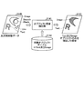
Regarding the configuration of the printing system, the function and configuration of the
DFE3250は、図32に例示されるように、レンダリングエンジン51と、版調整部511と、プレビュー処理部513と、si1部52と、TRC(Tone Reproduction Curve)53と、si2部54と、ハーフトーンエンジン55と、クリアプロセッシング56と、si3部57と、入力部58と、表示部59とを有する。ここで、レンダリングエンジン51、版調整部511、si1部52、TRC53、si2部54、ハーフトーンエンジン55、クリアプロセッシング56、si3部57、入力部58、表示部59の機能および構成については実施の形態1と同様である。
As illustrated in FIG. 32, the
プレビュー処理部513は、印刷データのプレビュー画像を生成して、生成されたプレビュー画像を表示部59に表示する。
The
図33は、実施の形態8にかかる版調整部511とプレビュー処理部513の機能的構成を示すブロック図である。図33に示すように、版調整部511の機能的構成は、図10で示した実施の形態1の版調整部511と同様である。
FIG. 33 is a block diagram of functional configurations of the
プレビュー処理部513は、図33に示すように、乖離度算出部3301と、プレビュー画像生成部3302とを備えている。乖離度算出部3301は、CMYKの各有色版データ5111を入力し、色分解処理部5117によるCMYKの有色版データ5111に対する色分解処理後の光沢度と、版調整部511の光沢度目標値決定部5113で決定された光沢度目標値との差分である乖離度を算出する。
As shown in FIG. 33, the
図34は、実施の形態8にかかる乖離度を乖離度を概念的に説明するための図である。図34の例では、ターゲットとする光沢度目標値に対して、色分解処理部5117により色分解処理を実行することで、入力画像データとなる有色版データ5111の光沢度が、色分解処理前の光沢度から改善されて光沢度目標値に近くはなるものの、色分解処理後の光沢度は光沢度目標値から乖離しているという状況が示されている。そして、図34には、光沢度目標値とと、色分解処理後の光沢度の差分の絶対値が乖離度として示されている。
FIG. 34 is a diagram for conceptually explaining the divergence degree according to the eighth embodiment. In the example of FIG. 34, the color
このように光沢度の乖離は入力画像全体を通して少なからずあり、その度合いの大小は各画素のCMYK値の総量に応じて異なるため、これを入力画像上で可視化することで乖離度を把握し易くできる。このため、本実施の形態では、以下に説明するように、乖離度が大きい領域を可視化してプレビュー表示している。 As described above, the glossiness divergence is not a little over the entire input image, and the degree of the difference varies depending on the total amount of CMYK values of each pixel. By visualizing this on the input image, it is easy to grasp the divergence degree. it can. For this reason, in this embodiment, as will be described below, a region with a large degree of divergence is visualized and previewed.
なお、図34の例では、光沢度目標値と、それに対する色分解処理後の光沢度の差分の絶対値を乖離度としているが、これに限定されるものではなく、任意の算出式を用いて乖離度を算出するように乖離度算出部3301を構成してもよい。
In the example of FIG. 34, the absolute value of the difference between the glossiness target value and the glossiness after the color separation process is used as the divergence degree, but the present invention is not limited to this, and an arbitrary calculation formula is used. The divergence
プレビュー画像生成部3302は、CMYKの有色版データ5111のプレビュー画像を生成する。具体的には、プレビュー画像生成部3302は、CMYKの有色版データ5111において、乖離度算出部3301で算出された乖離度が所定値以上の領域を他の領域と区別してプレビュー画像を生成する。プレビュー画像生成部3302は、生成したプレビュー画像を表示部59に送出する。これにより、表示部59はプレビュー画像を表示する。
The preview
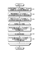
図35は、実施の形態8にかかる版調整処理およびプレビュー画像生成処理の手順の一例を示すフローチャートである。まず、光沢度目標値決定部5113は、実施の形態1と同様に、光沢度目標値テーブル5114を参照して、各CMYKの総量値における光沢度目標値を決定する(ステップS31)。
FIG. 35 is a flowchart of an example of a procedure of plate adjustment processing and preview image generation processing according to the eighth embodiment. First, the glossiness target
次に、印刷対象とする画像データである有色版データ5111の各画素に対して、以下のステップS32、S33、S3501、S3502の処理が実行される。ステップS32では、色分解量決定部5115が、実施の形態1と同様に、有色色材量対光沢度テーブル5116を参照して、上述したように、光沢度目標値を満たすための色分解量を決定する(ステップS32)。すなわち、色分解量決定部5115は、有色色材量対光沢度テーブル5116を元にCMYK値の総量に対する光沢度を参照し、これと光沢度目標値との差を元に、光沢度の不均一性がどの程度発生しているかを判断し、色分解処理をどの程度実施すべきかを決定する。これにより、色分解処理後のカラー版の光沢度がどの程度になるのかが決定される。そして、色分解量決定部5115は、決定された色分解量に基づいて色分解処理を行う(ステップS33)。
Next, the following steps S32, S33, S3501, and S3502 are performed on each pixel of the
以上から、光沢度目標値と色分解処理後のカラー版の光沢度の情報を得ることができるので、色分解処理が終了したら、この情報に基づいて、乖離度算出部3301は、ステップS31で決定された光沢度目標値と、ステップS33による色分解処理後の有色版データ5111の光沢度を比較して、両者の差分を求めることにより、乖離度を算出する(ステップS3501)。
From the above, it is possible to obtain the gloss target value and the gloss information of the color plate after the color separation process. When the color separation process is completed, the divergence
次に、プレビュー画像生成部3302は、乖離度に応じたプレビュー画像を生成して、生成したプレビュー画像を表示部59に表示する(ステップS3502)。
Next, the preview
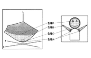
図36は、実施の形態8においてプレビュー画像が生成される流れを例示する図である。プレビュー画像生成部3302は、入力画像である有色版データ5111に対して、各画素におけるCMYK総量値を調査し、乖離度の値の大きさと濃度を合わせてマッピングすることで、プレビュー結果5133のようなプレビュー画像を生成することができる。例えば、図36に示すプレビュー結果5133のプレビュー画像では顔と両手の部分は乖離度が高く、胴と背景の部分は特に乖離は発生していない、というプレビュー結果が得られているのが分かる。
FIG. 36 is a diagram illustrating a flow of generating a preview image in the eighth embodiment. The preview
なお、図36の例示は、乖離度の値の大きさをそのまま濃度として表現し、入力画像にマッピングさせているが、これに限定されるものではない。例えば、図37に示すように、プレビュー画像生成処理を通して、一定の乖離度以上の画素領域のみを抽出して表示するようにプレビュー画像生成部3302を構成してもよい。
In the example of FIG. 36, the magnitude of the value of the divergence is expressed as a density as it is and is mapped to the input image, but is not limited to this. For example, as shown in FIG. 37, the preview
このように本実施の形態では、DFE3250が光沢度目標値と色分解処理後の光沢度との乖離度に応じたプレビュー画像を生成して表示しているので、ユーザはプレビュー画像を印刷実施前に表示部59で確認し判断することで、印刷設定を見直したり、入力画像そのもののデザインを見直したりすることができ、不要な印刷も回避することができる。
As described above, in this embodiment, the
すなわち、クリアトナーは有色トナーと比較して高価なものであり、印刷コストが嵩んでしまうが、本実施の形態により、印刷前に、狙いの光沢度目標値の光沢度を実現できそうか否かをユーザが確認することができる。これにより、ユーザは、使用する用紙、クリア版の設定、光沢度に乖離がある部分のデザイン(CMYK値)、使用するプロファイルの設定、総量規制値等の原稿設定や印刷設定を見直すことができる。このため、本実施の形態によれば、無駄な印刷を少なくすることができ、クリアトナーの使用を節約することが可能となる。 That is, the clear toner is more expensive than the colored toner and increases the printing cost. However, according to the present embodiment, whether or not the target glossiness target glossiness can be achieved before printing. The user can confirm whether or not. Thus, the user can review the document settings and print settings such as the paper to be used, the clear plate setting, the design of the part where the glossiness is different (CMYK value), the setting of the profile to be used, and the total amount regulation value. . For this reason, according to the present embodiment, it is possible to reduce unnecessary printing, and it is possible to save the use of clear toner.
(変形例1)
なお、さらに、乖離度が所定値以上の画素の画素値と頻度の一覧を、プレビュー画像の一部として生成するようにプレビュー画像生成部3302を構成することができる。図38は、変形例1にかかる、乖離度が所定値以上の画素の画素値と頻度の一覧を示す図である。図38では、光沢度目標値から乖離している画素値(CMYK)について、頻度の高い順にリストアップした例を示している。このようにしてプレビュー画像生成部3302は、生成した一覧を、プレビュー結果5133の一部として(プレビュー画像として)、図36や図37の表示例とともに表示部59に表示する。
(Modification 1)
Further, the preview
このようにプレビュー画像生成部3302が、光沢度の乖離度の大きさと、画素そのものの色値及び頻度について、具体的な値をリストアップすることでプレビュー表示時の客観性をより向上させることができる。
In this way, the preview
なお、図38の例では、上位4個までの画素値について例示しているが、4個に限定されるものではない。また、図38の例では、画素値としてCMYK値を例示しているが、これに限定されるものではなく、例えば、任意のCMYKプロファイル等を利用してCMYK値をLab値に変換して表示させるようにプレビュー画像生成部3302を構成してもよい。
In the example of FIG. 38, the top four pixel values are illustrated, but the number is not limited to four. In the example of FIG. 38, the CMYK value is exemplified as the pixel value. However, the pixel value is not limited to this. For example, the CMYK value is converted into a Lab value by using an arbitrary CMYK profile or the like. The preview
(変形例2)
さらに、乖離度が0以上の画素について、ガマット上での位置と有色版データ上の位置関係を示す画像を、プレビュー画像の一部として生成するようにプレビュー画像生成部3302を構成してもよい。
(Modification 2)
Further, the preview
図39は、変形例2において、光沢度目標値から乖離している各画素に対するガマット上での位置と入力画像である有色版データ上の位置との関係について表示する例を示す図である。プレビュー画像生成部3302は、図39に示す画像を、プレビュー結果5133の一部として、すなわちプレビュー画像の一部として生成する。
FIG. 39 is a diagram illustrating an example of displaying the relationship between the position on the gamut and the position on the color plane data that is the input image for each pixel deviating from the glossiness target value in the second modification. The preview
なお、図39では4か所までの画素領域について例示しているが、4箇所に限定されるものではない。 Note that although FIG. 39 illustrates up to four pixel regions, the present invention is not limited to four.
このように、プレビュー画像生成部3302が、入力画像内における光沢度の乖離度の大きい部分を可視化し、またガマット上での対応位置も把握することで、ユーザはプレビュー表示時に直観的に乖離度を把握し易くなり、客観性をより向上させることができる。
As described above, the preview
(変形例3)
乖離度を算出した後さらに、乖離度を、立体的な高さ情報に変換するように乖離度算出部3301を構成し、変換された立体的な高さ情報を合成してプレビュー画像を生成するようにプレビュー画像生成部3302を構成してもよい。
(Modification 3)
After calculating the divergence degree, the divergence
図40は、変形例3において、光沢度目標値からの乖離度を立体的な高さ情報に変換して表示する例を示す図である。プレビュー画像生成部3302は、図40に示す画像を、プレビュー結果5133の一部として、すなわちプレビュー画像の一部として生成する。
FIG. 40 is a diagram illustrating an example in which the degree of deviation from the glossiness target value is converted into three-dimensional height information and displayed in
なお、図40では、一定の乖離度以上の画素領域のみを対象として立体的に可視化した場合について例示しているが、一定の乖離度以上の表示に限定されるものではない。 In addition, in FIG. 40, although the case where it visualized stereoscopically only about the pixel area | region more than a fixed deviation degree is illustrated, it is not limited to the display more than a fixed deviation degree.
このように、プレビュー画像生成部3302が、入力画像内における光沢度の乖離度の大きさを立体的に可視化することにより、ユーザはプレビュー表示時に直観的に乖離度を把握し易くなり、客観性をより向上させることができる。
As described above, the preview
なお、上記実施の形態1〜8および変形例で実行される印刷制御プログラム、版調整プログラム、プレビュー処理プログラムは、ROM等に予め組み込まれて提供される。 Note that the print control program, the plate adjustment program, and the preview processing program executed in the first to eighth embodiments and the modified examples are provided by being incorporated in advance in a ROM or the like.
上記実施の形態1〜8および変形例で実行される印刷制御プログラム、版調整プログラム、プレビュー処理プログラムは、インストール可能な形式又は実行可能な形式のファイルでCD−ROM、フレキシブルディスク(FD)、CD−R、DVD(Digital Versatile Disk)等のコンピュータで読み取り可能な記録媒体に記録して提供するように構成してもよい。 The print control program, the plate adjustment program, and the preview processing program executed in the first to eighth embodiments and the modified examples are files in an installable format or an executable format, such as a CD-ROM, a flexible disk (FD), and a CD. The recording medium may be provided by being recorded on a computer-readable recording medium such as -R or DVD (Digital Versatile Disk).
さらに、上記実施の形態1〜8および変形例で実行される印刷制御プログラム、版調整プログラム、プレビュー処理プログラムを、インターネット等のネットワークに接続されたコンピュータ上に格納し、ネットワーク経由でダウンロードさせることにより提供するように構成しても良い。また、上記実施の形態1〜8および変形例で実行される印刷制御プログラム、版調整プログラム、プレビュー処理プログラムをインターネット等のネットワーク経由で提供または配布するように構成しても良い。 Further, the print control program, the plate adjustment program, and the preview processing program executed in the above-described first to eighth embodiments and the modified examples are stored on a computer connected to a network such as the Internet and downloaded via the network. You may comprise so that it may provide. In addition, the print control program, the plate adjustment program, and the preview processing program executed in the first to eighth embodiments and the modifications may be provided or distributed via a network such as the Internet.
上記実施の形態1〜8および変形例で実行される印刷制御プログラム、版調整プログラム、プレビュー処理プログラムは、上述した各部を含むモジュール構成となっており、実際のハードウェアとしてはCPU(プロセッサ)が上記ROMから各プログラムを読み出して実行することにより上記各部が主記憶装置上にロードされて各部が主記憶装置上に生成されるようになっている。 The print control program, the plate adjustment program, and the preview processing program executed in the first to eighth embodiments and the modifications have a module configuration including the above-described units, and a CPU (processor) is used as actual hardware. By reading each program from the ROM and executing it, each unit is loaded onto the main storage device, and each unit is generated on the main storage device.
なお、本発明は前記実施形態そのままに限定されるものではなく、実施段階ではその要旨を逸脱しない範囲で構成要素を変形して具体化できる。また、前記実施形態に開示されている複数の構成要素の適宜な組み合わせにより、種々の発明を形成できる。例えば、実施形態に示される全構成要素から幾つかの構成要素を削除してもよい。さらに、異なる実施形態にわたる構成要素を適宜組み合わせてもよい。また、以下に例示するような種々の変形が可能である。 Note that the present invention is not limited to the above-described embodiment as it is, and can be embodied by modifying the constituent elements without departing from the scope of the invention in the implementation stage. Various inventions can be formed by appropriately combining a plurality of constituent elements disclosed in the embodiment. For example, some components may be deleted from all the components shown in the embodiment. Furthermore, constituent elements over different embodiments may be appropriately combined. Further, various modifications as exemplified below are possible.
10 ホスト装置
50 DFE
51 レンダリングエンジン
52 si1部
53 TRC
54 si2部
55 ハーフトーンエンジン
56 クリアプロセッシング
57 si3部
60 MIC
70 プリンタ機
80 グロッサ
90 低温定着機
511 版調整部
513 プレビュー処理部
3301 乖離度算出部
3302 プレビュー画像生成部
5111,5121 有色版データ
5112,5122 光沢制御版データ
5113 光沢度目標値決定部
5114 光沢度目標値テーブル
5115 色分解量決定部
5116 有色色材量対光沢度テーブル
5117 色分解処理部
5131 表面効果領域抽出部
5132 表面効果選択テーブル
5140 オブジェクト情報
5141 オブジェクト領域抽出部
5142 対象オブジェクトテーブル
5151 クリア色材量決定部
5152 クリア色材量対光沢度テーブル
5153 クリア色材量調整部
10
51
54
70
Claims (15)
前記光沢度目標値に対し、複数の有色材の各有色材に配分する色材量である各有色材の色分解量を、前記複数の有色材の各色材量の総和に基づいて決定する色分解量決定部と、
前記各有色材の色分解量に基づいて、複数の有色版データのそれぞれの間の色の置換を実行する色分解処理部と、
色の置換が実行された複数の有色版データに基づいて、前記画像データを生成する画像データ生成部と、
を備えた印刷制御装置。 A gloss target value determining unit for determining a gloss target value indicating a gloss target of image data to be printed;
A color that determines a color separation amount of each color material, which is a color material amount to be distributed to each color material of a plurality of color materials, based on a total sum of each color material amount of the plurality of color materials with respect to the gloss target value A decomposition amount determination unit;
Based on the color separation amount of each colored material, a color separation processing unit that performs color replacement between each of the plurality of colored plane data; and
An image data generation unit that generates the image data based on a plurality of color plane data that has undergone color replacement;
A printing control apparatus.
請求項1に記載の印刷制御装置。 The glossiness target value determining unit determines the glossiness target value according to the type of recording medium.
The print control apparatus according to claim 1.
請求項1に記載の印刷制御装置。 The glossiness target value determination unit determines the glossiness target value based on gloss control plane data that specifies the type of surface effect to be applied to the recording medium and the area on the recording medium to which the surface effect is applied. ,
The print control apparatus according to claim 1.
請求項1に記載の印刷制御装置。 The glossiness target value determining unit determines the glossiness target value according to an instruction from a user;
The print control apparatus according to claim 1.
前記色分解量決定部は、抽出された領域に対して、前記各有色材の色分解量を決定し、
前記色分解処理部は、前記抽出された領域に対して、前記色分解量に基づいて、前記色の置換を実行する、
請求項1〜4のいずれか一つに記載の印刷制御装置。 Surface effect region extraction unit for extracting a region to which a specific surface effect is applied based on gloss control plane data that specifies the type of surface effect to be applied to the recording medium and the region in the recording medium to which the surface effect is applied Further comprising
The color separation amount determination unit determines the color separation amount of each colored material for the extracted region,
The color separation processing unit performs the color replacement on the extracted region based on the color separation amount.
The printing control apparatus as described in any one of Claims 1-4.
前記色分解量決定部は、抽出されたオブジェクト領域に対して、前記各有色材の色分解量を決定し、
前記色分解処理部は、前記抽出されたオブジェクト領域に対して、前記色分解量に基づいて、前記色の置換を実行する、
請求項1〜5のいずれか一つに記載の印刷制御装置。 An object region extraction unit that extracts an object region that is a region of a specific drawing object from the color plane data;
The color separation amount determination unit determines the color separation amount of each colored material for the extracted object region,
The color separation processing unit performs the color replacement on the extracted object region based on the color separation amount.
The printing control apparatus as described in any one of Claims 1-5.
決定されたクリア色材量に基づいて、前記クリア色材量を調整するクリア色材量調整部と、
をさらに備えた請求項1〜6のいずれか一つに記載の印刷制御装置。 Glossiness after color separation processing for the plurality of color plane data, glossiness by gloss control plane data specifying the type of surface effect to be applied to the recording medium and the area in the recording medium to which the surface effect is applied, A clear color material amount determining unit that determines a clear color material amount that is a color material amount of the clear color material based on the gloss target value;
A clear color material amount adjusting unit for adjusting the clear color material amount based on the determined clear color material amount;
The printing control apparatus according to any one of claims 1 to 6, further comprising:
前記乖離度に基づいて、前記画像データのプレビュー画像を生成するプレビュー画像生成部と、
前記プレビュー画像を表示する表示部と、
をさらに備えた請求項1〜7のいずれか一つに記載の印刷制御装置。 A divergence degree calculating unit that calculates a divergence degree that is a difference between the glossiness after color separation processing on the plurality of color plane data and the glossiness target value;
A preview image generation unit that generates a preview image of the image data based on the degree of deviation;
A display unit for displaying the preview image;
The print control apparatus according to claim 1, further comprising:
請求項8に記載の印刷制御装置。 The preview image generation unit generates the preview image showing the areas where the divergence degree is a predetermined value or more;
The print control apparatus according to claim 8.
請求項8または9に記載の印刷制御装置。 The preview image generation unit further generates a list of pixel values and frequencies of pixels having the divergence degree equal to or greater than a predetermined value as a part of the preview image.
The print control apparatus according to claim 8 or 9.
請求項8〜10のいずれか一つに記載の印刷制御装置。 The preview image generation unit further generates, as a part of the preview image, an image indicating a positional relationship on a gamut and a position on the image data for a pixel having a divergence degree of 0 or more.
The print control apparatus according to claim 8.
前記プレビュー画像生成部は、前記立体的な高さ情報を合成して前記プレビュー画像を生成する、
請求項8〜11のいずれか一つに記載の印刷制御装置。 The divergence degree calculation unit further converts the divergence degree into three-dimensional height information,
The preview image generation unit generates the preview image by combining the three-dimensional height information;
The print control apparatus according to any one of claims 8 to 11.
印刷対象の画像データの光沢度の目標を示す光沢度目標値を決定する光沢度目標値決定部と、
前記光沢度目標値に対し、複数の有色材の各有色材に配分する色材量である各有色材の色分解量を、前記複数の有色材の各色材量の総和に基づいて決定する色分解量決定部と、
前記各有色材の色分解量に基づいて、複数の有色版データのそれぞれの間の色の置換を実行する色分解処理部と、
色の置換が実行された複数の有色版データに基づいて、前記画像データを生成する画像データ生成部と、
を備えた印刷制御システム。 A print control system for generating image data,
A gloss target value determining unit for determining a gloss target value indicating a gloss target of image data to be printed;
A color that determines a color separation amount of each color material, which is a color material amount to be distributed to each color material of a plurality of color materials, based on a total sum of each color material amount of the plurality of color materials with respect to the gloss target value A decomposition amount determination unit;
Based on the color separation amount of each colored material, a color separation processing unit that performs color replacement between each of the plurality of colored plane data; and
An image data generation unit that generates the image data based on a plurality of color plane data that has undergone color replacement;
Printing control system with.
前記光沢度目標値に対し、複数の有色材の各有色材に配分する色材量である各有色材の色分解量を、前記複数の有色材の各色材量の総和に基づいて決定し、
前記各有色材の色分解量に基づいて、複数の有色版データのそれぞれの間の色の置換を実行し、
色の置換が実行された複数の有色版データに基づいて、前記画像データを生成する、
ことを含む印刷制御方法。 Determine the gloss target value that indicates the target gloss level of the image data to be printed,
A color separation amount of each color material that is a color material amount to be distributed to each color material of a plurality of color materials is determined based on a total sum of each color material amount of the plurality of color materials with respect to the gloss target value.
Based on the color separation amount of each colored material, a color replacement between each of the plurality of colored plate data is performed,
Generating the image data based on a plurality of color plane data on which color replacement has been performed;
A printing control method.
前記光沢度目標値に対し、複数の有色材の各有色材に配分する色材量である各有色材の色分解量を、前記複数の有色材の各色材量の総和に基づいて決定し、
前記各有色材の色分解量に基づいて、複数の有色版データのそれぞれの間の色の置換を実行し、
色の置換が実行された複数の有色版データに基づいて、前記画像データを生成する、
ことをコンピュータに実行させるためのプログラム。 Determine the gloss target value that indicates the target gloss level of the image data to be printed,
A color separation amount of each color material that is a color material amount to be distributed to each color material of a plurality of color materials is determined based on a total sum of each color material amount of the plurality of color materials with respect to the gloss target value.
Based on the color separation amount of each colored material, a color replacement between each of the plurality of colored plate data is performed,
Generating the image data based on a plurality of color plane data on which color replacement has been performed;
A program that causes a computer to execute.
Priority Applications (2)
| Application Number | Priority Date | Filing Date | Title |
|---|---|---|---|
| JP2013270273A JP2014199644A (en) | 2013-03-15 | 2013-12-26 | Print controlling device, print controlling system, print controlling method and program |
| US14/578,871 US9291979B2 (en) | 2013-03-15 | 2014-12-22 | Device, system, method, and recording medium having computer program for controlling printing |
Applications Claiming Priority (3)
| Application Number | Priority Date | Filing Date | Title |
|---|---|---|---|
| JP2013054434 | 2013-03-15 | ||
| JP2013054434 | 2013-03-15 | ||
| JP2013270273A JP2014199644A (en) | 2013-03-15 | 2013-12-26 | Print controlling device, print controlling system, print controlling method and program |
Publications (1)
| Publication Number | Publication Date |
|---|---|
| JP2014199644A true JP2014199644A (en) | 2014-10-23 |
Family
ID=52356473
Family Applications (1)
| Application Number | Title | Priority Date | Filing Date |
|---|---|---|---|
| JP2013270273A Pending JP2014199644A (en) | 2013-03-15 | 2013-12-26 | Print controlling device, print controlling system, print controlling method and program |
Country Status (2)
| Country | Link |
|---|---|
| US (1) | US9291979B2 (en) |
| JP (1) | JP2014199644A (en) |
Cited By (3)
| Publication number | Priority date | Publication date | Assignee | Title |
|---|---|---|---|---|
| JP2016085320A (en) * | 2014-10-24 | 2016-05-19 | 京セラドキュメントソリューションズ株式会社 | Image forming apparatus |
| JP2018205396A (en) * | 2017-05-31 | 2018-12-27 | 株式会社沖データ | Image forming apparatus and image forming method |
| JP7301678B2 (en) | 2019-08-30 | 2023-07-03 | キヤノン株式会社 | system, how to control it |
Families Citing this family (3)
| Publication number | Priority date | Publication date | Assignee | Title |
|---|---|---|---|---|
| JP5845986B2 (en) | 2011-03-18 | 2016-01-20 | 株式会社リコー | PRINT CONTROL DEVICE, PRINT SYSTEM, PRINT CONTROL METHOD, AND PROGRAM |
| JP6834159B2 (en) * | 2016-03-23 | 2021-02-24 | 富士ゼロックス株式会社 | Image forming device and image forming program |
| US10477038B2 (en) | 2017-05-15 | 2019-11-12 | Ricoh Company, Ltd. | Image processing apparatus, image processing system, and recording medium |
Citations (2)
| Publication number | Priority date | Publication date | Assignee | Title |
|---|---|---|---|---|
| JP2012185380A (en) * | 2011-03-07 | 2012-09-27 | Fuji Xerox Co Ltd | Image processing device, image forming apparatus, and program |
| JP2012208929A (en) * | 2011-03-17 | 2012-10-25 | Ricoh Co Ltd | Print controller, print control system, print control method, and print control program |
Family Cites Families (30)
| Publication number | Priority date | Publication date | Assignee | Title |
|---|---|---|---|---|
| JP2006168107A (en) | 2004-12-15 | 2006-06-29 | Canon Inc | Inkjet recording method and recorded matter |
| JP5094100B2 (en) | 2005-12-06 | 2012-12-12 | キヤノン株式会社 | Image forming apparatus |
| US8086124B2 (en) | 2005-12-06 | 2011-12-27 | Canon Kabushiki Kaisha | Image forming apparatus |
| JP2011043683A (en) | 2009-08-21 | 2011-03-03 | Ricoh Co Ltd | Image forming apparatus and image forming method |
| JP2011059445A (en) | 2009-09-10 | 2011-03-24 | Ricoh Co Ltd | Image forming apparatus, method of forming preview image, and program |
| JP2011150026A (en) | 2010-01-19 | 2011-08-04 | Ricoh Co Ltd | Image processor, image processing method, and program |
| JP5451418B2 (en) | 2010-01-22 | 2014-03-26 | キヤノン株式会社 | Image forming apparatus |
| JP2011170125A (en) | 2010-02-19 | 2011-09-01 | Ricoh Co Ltd | Image forming apparatus and image forming method |
| US8681377B2 (en) | 2010-08-30 | 2014-03-25 | Canon Kabushiki Kaisha | Image processing apparatus, image processing method, and program for executing printing using transparent recording material |
| JP5794062B2 (en) * | 2010-09-15 | 2015-10-14 | 株式会社リコー | Information processing apparatus, data generation method, and program |
| JP5842488B2 (en) * | 2010-09-15 | 2016-01-13 | 株式会社リコー | Print control apparatus, image forming system, print control method, printed material manufacturing method, and program |
| JP6019635B2 (en) * | 2011-03-18 | 2016-11-02 | 株式会社リコー | Information processing apparatus, printer driver program, and image forming system |
| JP5845986B2 (en) * | 2011-03-18 | 2016-01-20 | 株式会社リコー | PRINT CONTROL DEVICE, PRINT SYSTEM, PRINT CONTROL METHOD, AND PROGRAM |
| JP5910185B2 (en) * | 2011-03-18 | 2016-04-27 | 株式会社リコー | Print control apparatus, print control system, print control method, and program |
| JP6019916B2 (en) * | 2011-09-14 | 2016-11-02 | 株式会社リコー | Display processing apparatus, image forming system, display processing method, and program |
| JP5994485B2 (en) * | 2011-09-14 | 2016-09-21 | 株式会社リコー | Display processing apparatus, image forming system, and display processing program |
| JP5928051B2 (en) * | 2012-03-22 | 2016-06-01 | 株式会社リコー | Information processing apparatus, information processing system, and output method |
| JP2013235567A (en) * | 2012-04-11 | 2013-11-21 | Ricoh Co Ltd | Print control device, print control system, print control method, and print control program |
| JP5919993B2 (en) * | 2012-04-18 | 2016-05-18 | 株式会社リコー | Print control apparatus, print control method, and program |
| JP6115216B2 (en) * | 2012-04-18 | 2017-04-19 | 株式会社リコー | Print control apparatus, print control system, print control method, and program |
| JP2013222161A (en) * | 2012-04-18 | 2013-10-28 | Ricoh Co Ltd | Print control device, print control system, print control method, and program |
| JP6115217B2 (en) * | 2012-04-18 | 2017-04-19 | 株式会社リコー | Print control apparatus, print control system, print control method, and program |
| JP2014199410A (en) * | 2013-03-15 | 2014-10-23 | 株式会社リコー | Print control device, print control system, and print control method and program |
| JP2014199638A (en) * | 2013-03-15 | 2014-10-23 | 株式会社リコー | Print control device, print control system, and print control method and program |
| JP6155978B2 (en) * | 2013-08-28 | 2017-07-05 | 株式会社リコー | Print control apparatus, image forming system, and program |
| JP6163975B2 (en) * | 2013-08-28 | 2017-07-19 | 株式会社リコー | Print control apparatus, image forming system, and program |
| JP2015049255A (en) * | 2013-08-29 | 2015-03-16 | 株式会社リコー | Image forming apparatus, image forming system, and image forming method |
| JP2015084085A (en) * | 2013-09-17 | 2015-04-30 | 株式会社リコー | Image forming apparatus, image forming method, and program |
| JP6217339B2 (en) * | 2013-11-20 | 2017-10-25 | 株式会社リコー | Print control apparatus, print control method, and program |
| JP2015135477A (en) * | 2013-12-20 | 2015-07-27 | 株式会社リコー | Image processing apparatus, image forming system, image processing method, and program |
-
2013
- 2013-12-26 JP JP2013270273A patent/JP2014199644A/en active Pending
-
2014
- 2014-12-22 US US14/578,871 patent/US9291979B2/en active Active
Patent Citations (2)
| Publication number | Priority date | Publication date | Assignee | Title |
|---|---|---|---|---|
| JP2012185380A (en) * | 2011-03-07 | 2012-09-27 | Fuji Xerox Co Ltd | Image processing device, image forming apparatus, and program |
| JP2012208929A (en) * | 2011-03-17 | 2012-10-25 | Ricoh Co Ltd | Print controller, print control system, print control method, and print control program |
Cited By (3)
| Publication number | Priority date | Publication date | Assignee | Title |
|---|---|---|---|---|
| JP2016085320A (en) * | 2014-10-24 | 2016-05-19 | 京セラドキュメントソリューションズ株式会社 | Image forming apparatus |
| JP2018205396A (en) * | 2017-05-31 | 2018-12-27 | 株式会社沖データ | Image forming apparatus and image forming method |
| JP7301678B2 (en) | 2019-08-30 | 2023-07-03 | キヤノン株式会社 | system, how to control it |
Also Published As
| Publication number | Publication date |
|---|---|
| US9291979B2 (en) | 2016-03-22 |
| US20150185678A1 (en) | 2015-07-02 |
Similar Documents
| Publication | Publication Date | Title |
|---|---|---|
| US9671740B2 (en) | Print control apparatus, printing system, and print control method | |
| JP5794062B2 (en) | Information processing apparatus, data generation method, and program | |
| JP6019635B2 (en) | Information processing apparatus, printer driver program, and image forming system | |
| JP5966546B2 (en) | Display processing apparatus, display processing system, display processing method, and program | |
| JP5928051B2 (en) | Information processing apparatus, information processing system, and output method | |
| US20130278952A1 (en) | Print controlling apparatus, print controlling system, print controlling method, and computer program product | |
| US9291979B2 (en) | Device, system, method, and recording medium having computer program for controlling printing | |
| US20130271792A1 (en) | Information processing apparatus, information processing system, information processing method, and computer-readable storage medium | |
| US9606494B2 (en) | Printing control device and printing control system that generate toner-scattering prevention plane data | |
| JP6056255B2 (en) | Control device, image forming system, and program | |
| US9223281B2 (en) | Image processing apparatus, image forming system, and computer-readable recording medium having gloss control | |
| JP6136409B2 (en) | Display device | |
| JP2015049255A (en) | Image forming apparatus, image forming system, and image forming method | |
| JP2015094826A (en) | Information processing apparatus, information processing system, information processing method, and program | |
| US20150098740A1 (en) | Print control device, print control method, and computer-readable storage medium | |
| JP5910266B2 (en) | Print control apparatus, image forming system, print control method, and program | |
| JP5365755B2 (en) | Print production method and print | |
| JP5990993B2 (en) | Print control apparatus, print control system, print control method, and program | |
| US9256185B2 (en) | Printing control device, image forming system, and non-transitory computer-readable medium | |
| JP2013235567A (en) | Print control device, print control system, print control method, and print control program | |
| JP2016042182A (en) | Image processing apparatus, image processing method, and image processing system | |
| JP5982975B2 (en) | Print control apparatus, print control system, print control method, and program | |
| JP2013222159A (en) | Information processor, information processing system, and total amount regulation method | |
| JP6044685B2 (en) | Printing system | |
| JP5978726B2 (en) | Print control apparatus, print control system, and program |
Legal Events
| Date | Code | Title | Description |
|---|---|---|---|
| A621 | Written request for application examination |
Free format text: JAPANESE INTERMEDIATE CODE: A621 Effective date: 20161208 |
|
| A131 | Notification of reasons for refusal |
Free format text: JAPANESE INTERMEDIATE CODE: A131 Effective date: 20170815 |
|
| A977 | Report on retrieval |
Free format text: JAPANESE INTERMEDIATE CODE: A971007 Effective date: 20170823 |
|
| A02 | Decision of refusal |
Free format text: JAPANESE INTERMEDIATE CODE: A02 Effective date: 20180220 |