JP2014196014A - Side crash passenger protector - Google Patents

Side crash passenger protector Download PDF

Info

Publication number
JP2014196014A
JP2014196014A JP2013071826A JP2013071826A JP2014196014A JP 2014196014 A JP2014196014 A JP 2014196014A JP 2013071826 A JP2013071826 A JP 2013071826A JP 2013071826 A JP2013071826 A JP 2013071826A JP 2014196014 A JP2014196014 A JP 2014196014A
Authority
JP
Japan
Prior art keywords
occupant
airbag
belt
thigh
belt guide
Prior art date
Legal status (The legal status is an assumption and is not a legal conclusion. Google has not performed a legal analysis and makes no representation as to the accuracy of the status listed.)
Pending
Application number
JP2013071826A
Other languages
Japanese (ja)
Inventor
桑原 正明
Masaaki Kuwabara
正明 桑原
Current Assignee (The listed assignees may be inaccurate. Google has not performed a legal analysis and makes no representation or warranty as to the accuracy of the list.)
Toyota Motor Corp
Original Assignee
Toyota Motor Corp
Priority date (The priority date is an assumption and is not a legal conclusion. Google has not performed a legal analysis and makes no representation as to the accuracy of the date listed.)
Filing date
Publication date
Application filed by Toyota Motor Corp filed Critical Toyota Motor Corp
Priority to JP2013071826A priority Critical patent/JP2014196014A/en
Publication of JP2014196014A publication Critical patent/JP2014196014A/en
Pending legal-status Critical Current

Links

Images

Abstract

PROBLEM TO BE SOLVED: To provide a side crash passenger protector capable of reducing an input load to a passenger's waist during a side crash as compared with a conventional technique.SOLUTION: A thigh constraining device 30 comprises: a belt guide 31 supported by a lap belt 23; and an inner airbag 32 expanded and deployed between right and left thigh parts P2 and P1 of a passenger P from the belt guide 31 during a side crash. Owing to this, during a side crash, the thigh part P1 or P2 on an opposite side to a crash side can be constrained using the inner airbag 32. As a result, it is possible for the thigh part P1 or P2 on the opposite side to the crash side to take responsibility for a load input to the passenger and to reduce the load input to a passenger's waist as compared with a conventional technique.

Description

本発明は、側面衝突用の乗員保護装置に関する。   The present invention relates to an occupant protection device for side collision.

特許文献1は、側面衝突時(以下、側突時ともいう)に乗員の側方にて膨張展開して、乗員の肩部から腰部を保護するサイドエアバッグ装置を開示している。また、特許文献2は、ドアトリムに設けられており側突時に腰部を保護する腰部エネルギー吸収手段としてのエネルギー吸収パッドと、大腿部を保護する大腿部エネルギー吸収手段としての大腿部用サイドエアバッグと、を有する乗員保護装置を開示している。 Patent Document 1 discloses a side airbag device that is inflated and deployed on the side of an occupant during a side collision (hereinafter also referred to as a side collision) to protect the waist from the occupant's shoulder. Patent Document 2 discloses an energy absorbing pad as a waist energy absorbing means that is provided on a door trim and protects the waist during a side collision, and a thigh side as a thigh energy absorbing means that protects the thigh. An occupant protection device having an airbag is disclosed.

乗員の着座位置を変化させずに側突時における乗員腰部への荷重を低減する方法には、(i)乗員保護装置と乗員とが接触するタイミングの早期化、(ii)乗員保護装置と乗員との接触面積の増加、などがある。しかし、上記(i)では、衝突検知やエアバッグの作動を早期化する必要がある。また、上記(ii)では、ダミーの体格が変化しない場合、エネルギー吸収パッドと乗員との接触面積の増加には限界がある。   The method of reducing the load on the occupant's waist during a side collision without changing the seating position of the occupant includes (i) accelerating the timing of contact between the occupant protection device and the occupant, and (ii) the occupant protection device and the occupant. Contact area increase. However, in (i) above, it is necessary to accelerate collision detection and airbag operation. In (ii) above, there is a limit to the increase in the contact area between the energy absorbing pad and the occupant when the dummy physique does not change.

特許第4168283号公報Japanese Patent No. 4168283 特許第4678356号公報Japanese Patent No. 4678356

本発明の目的は、従来に比べて、側突時における乗員腰部への入力荷重を低減できる側面衝突用乗員保護装置を提供することにある。   An object of the present invention is to provide an occupant protection device for side collision that can reduce an input load to an occupant's waist at the time of a side collision, as compared with the related art.

上記目的を達成する本発明はつぎの通りである。
(1)上記課題を解決する本発明に係る側面衝突用乗員保護装置では、タングプレートをバックルに係合してベルト装着したときにラップベルトを備えるシートベルトと、前記ラップベルトに支持されるベルトガイドおよび側突時に該ベルトガイドから乗員の左右大腿部間に膨張展開する内側エアバッグを備える大腿部拘束装置と、を有する。
(2)上記(1)において、前記大腿部拘束装置は、さらに、前記内側エアバッグの左右両側に配置され膨張展開時に乗員の大腿部の上面から外側面にわたって接触する外側エアバッグを備える。
(3)上記(2)において、前記内側エアバッグが前記外側エアバッグに先行して膨張展開を開始する。
(4)上記(1)〜(3)のいずれか1つにおいて、前記ベルトガイドは、前記ラップベルトに対して該ラップベルトの長手方向に可動に設けられており、
前記大腿部拘束装置は、さらに、前記タングプレートと前記ベルトガイドとを繋ぐストラップを備える。
The present invention for achieving the above object is as follows.
(1) In the side collision occupant protection device according to the present invention for solving the above problems, a seat belt including a lap belt when the tongue plate is engaged with the buckle and the belt is mounted, and a belt supported by the lap belt A thigh restraint device including an inner airbag that inflates and deploys between the guide and the belt guide between the left and right thighs of the occupant during the side collision.
(2) In the above (1), the thigh restraint device further includes an outer airbag that is disposed on both the left and right sides of the inner airbag and that contacts the upper surface of the occupant's thigh from the outer surface when inflated and deployed. .
(3) In the above (2), the inner airbag starts inflating and deploying prior to the outer airbag.
(4) In any one of the above (1) to (3), the belt guide is provided movably in the longitudinal direction of the lap belt with respect to the lap belt,
The thigh restraint device further includes a strap connecting the tongue plate and the belt guide.

上記(1)の側面衝突用乗員保護装置によれば、大腿部拘束装置が、ラップベルトに支持されるベルトガイドと、側突時にベルトガイドから乗員の左右大腿部間に膨張展開する内側エアバッグと、を備えるため、内側エアバッグを用いて側突時に反衝突側の大腿部を拘束できる。この結果、乗員へ入力する荷重を反衝突側の大腿部にも受け持たせることができ、乗員腰部へ入力する荷重を従来に比べて低減できる。 According to the side collision occupant protection device according to (1) above, the thigh restraint device is inflated and deployed between the belt guide supported by the lap belt and between the belt guide and the left and right thighs of the occupant during a side collision. Therefore, the thigh on the anti-collision side can be restrained at the time of a side collision using the inner airbag. As a result, the load input to the occupant can be applied to the thigh on the anti-collision side, and the load input to the occupant waist can be reduced as compared with the conventional case.

上記(2)の側面衝突用乗員保護装置によれば、大腿部拘束装置が、さらに、内側エアバッグの左右両側に配置され膨張展開時に乗員の大腿部の上面から外側面にわたって接触する外側エアバッグを備えるため、内側エアバッグを用いて大腿部を拘束するだけでなく外側エアバッグを用いても側突時に大腿部を拘束できる。よって、外側エアバッグが設けられていない場合に比べて、乗員腰部へ入力する荷重をさらに低減できる。また、外側エアバッグにより内側エアバッグが乗員の大腿部に対して左右にずれることを抑制でき、内側エアバッグを確実に乗員の大腿部間に膨張展開させることができる。 According to the side collision occupant protection device of (2) above, the thigh restraint device is further arranged on both the left and right sides of the inner airbag and is in contact with the occupant's thigh from the upper surface to the outer surface during inflation and deployment. Since the airbag is provided, the thigh can be restrained at the time of a side collision not only by restraining the thigh using the inner airbag but also by using the outer airbag. Therefore, compared with the case where the outside airbag is not provided, the load input to the occupant waist can be further reduced. Moreover, it can suppress that an inner side airbag shifts | deviates to right and left with respect to a passenger | crew's thigh by an outer side airbag, and an inner side airbag can be reliably inflate-deployed between a passenger | crew's thigh.

上記(3)の側面衝突用乗員保護装置によれば、内側エアバッグが外側エアバッグに先行して膨張展開を開始するため、プリテンショナの作動によりシートベルトによる乗員の拘束開始が早められている場合であっても、内側エアバッグを確実に乗員の左右大腿部間に膨張展開させることができる。   According to the side collision occupant protection device of (3) above, since the inner airbag starts inflating and deploying prior to the outer airbag, the start of restraint of the occupant by the seat belt is accelerated by the operation of the pretensioner. Even in this case, the inner airbag can be reliably inflated and deployed between the left and right thighs of the occupant.

上記(4)の側面衝突用乗員保護装置によれば、ベルトガイドが、ラップベルトに対してラップベルトの長手方向に可動に設けられているため、乗員の体型に合わせてベルトガイドをラップベルトに対して移動させることができ、乗員の体型によらずに内側エアバッグを乗員の左右大腿部間に膨張展開させることができる。また、大腿部拘束装置が、さらに、タングプレートとベルトガイドとを繋ぐストラップを備えるため、エアバッグが膨張展開していないときにベルトガイドが乗員に対して車両外側へずれる量を抑制でき、内側エアバッグを乗員の大腿部間に確実に膨張展開させることができる。   According to the side collision occupant protection device of (4) above, since the belt guide is provided movably in the longitudinal direction of the lap belt with respect to the lap belt, the belt guide is used as the lap belt according to the occupant's body shape. The inner airbag can be inflated and deployed between the left and right thighs of the occupant regardless of the occupant's body shape. Further, since the thigh restraint device further includes a strap that connects the tongue plate and the belt guide, the amount of the belt guide that shifts to the outside of the vehicle with respect to the occupant when the airbag is not inflated and deployed can be suppressed. The inner airbag can be surely inflated and deployed between the thighs of the occupant.

車両正面視における、本発明実施例の大腿部拘束装置が作動しているときにおける側面衝突用乗員保護装置の概略図である。1 is a schematic diagram of a side collision occupant protection device when a thigh restraint device of an embodiment of the present invention is operating in a vehicle front view. FIG. 車両左側面視における、本発明実施例の大腿部拘束装置が作動しているときにおける側面衝突用乗員保護装置の概略図である。1 is a schematic view of a side collision occupant protection device when a thigh restraint device according to an embodiment of the present invention is operating in a left side view of a vehicle. 車両上面視における、本発明実施例の大腿部拘束装置が作動しているときにおける側面衝突用乗員保護装置の概略図である。1 is a schematic view of a side collision occupant protection device when a thigh restraint device according to an embodiment of the present invention is operating in a vehicle top view. FIG. 車両上面視における、本発明実施例の大腿部拘束装置が作動していないときにおける概略図である。FIG. 3 is a schematic view when the thigh restraint device according to the embodiment of the present invention is not operating in a vehicle top view. 車両正面視における、本発明実施例の大腿部拘束装置が作動していないときにおける概略図である。FIG. 3 is a schematic view when the thigh restraint device of the embodiment of the present invention is not operating in a vehicle front view. 車両上面視における、本発明実施例の大腿部拘束装置が作動しているときにおける概略図である。FIG. 3 is a schematic view when the thigh restraint device of the embodiment of the present invention is operating in a vehicle top view. 車両正面視における、本発明実施例の大腿部拘束装置が作動しているときにおける概略図である。It is the schematic when the thigh restraint device of the example of the present invention is operating in the vehicle front view. 本発明実施例のエアバッグの展開順を示す工程図である。It is process drawing which shows the expansion | deployment order of the airbag of this invention Example.

以下に、本発明実施例の側面衝突用乗員保護装置(以下、単に保護装置ともいう)を、図面を参照して説明する。なお、図は、シート1が運転席である場合を示しているが、シートは助手席であってもよく後部座席であってもよい。図中、UPは上側を示し、FRは車両前側を示し、OUTは車両幅方向外側を示す。   Hereinafter, a side collision occupant protection device (hereinafter also simply referred to as a protection device) according to an embodiment of the present invention will be described with reference to the drawings. Although the figure shows the case where the seat 1 is a driver's seat, the seat may be a passenger seat or a rear seat. In the figure, UP indicates the upper side, FR indicates the front side of the vehicle, and OUT indicates the outer side in the vehicle width direction.

本発明実施例の保護装置10は、シート1に着席している乗員Pを拘束するために設けられており、図1に示すように、シートベルト20と、大腿部拘束装置(以下、単に拘束装置ともいう)30と、を有する。 The protection device 10 according to the embodiment of the present invention is provided to restrain an occupant P seated on the seat 1, and as shown in FIG. 1, a seat belt 20 and a thigh restraint device (hereinafter simply referred to as a thigh restraint device). 30).

シート1は、乗員Pが着座するシートクッション1aと、シートクッション1aの車両後側端部に配置され乗員Pの背もたれとして利用されるシートバック1bと、シートバック1bより上方に設けられ乗員Pの頭部を車両後側から支持するヘッドレスト1cと、を備える。 The seat 1 includes a seat cushion 1a on which the occupant P is seated, a seat back 1b that is used as a backrest of the occupant P disposed at a rear end of the seat cushion 1a, and a seat back 1b that is provided above the seat back 1b. A headrest 1c that supports the head from the rear side of the vehicle.

シートベルト20は、3点式のシートベルトである。シートベルト20は、1本のウエビング21で構成されており、ベルト装着時に車外側上方から車内側下方に延び乗員Pの胸前に位置するショルダベルト22と、ベルト装着時に乗員Pの腰前に位置するラップベルト23と、を備える。シートベルト20の長手方向一端部は、車両のピラー2に配置され車両に対して固定されるリトラクタ24につながれており、シートベルト20の長手方向他端部は、シートクッション1aより車外側かつ後方に配置されるラップアウターアンカ25に固定されている。 The seat belt 20 is a three-point seat belt. The seat belt 20 is composed of a single webbing 21, which extends from the upper outside of the vehicle to the lower inside of the vehicle when the belt is worn, and is located in front of the chest of the occupant P. And a lap belt 23 that is positioned. One end in the longitudinal direction of the seat belt 20 is connected to a retractor 24 that is disposed on the pillar 2 of the vehicle and is fixed to the vehicle, and the other end in the longitudinal direction of the seat belt 20 is outside and rearward of the seat cushion 1a. It is being fixed to the lap outer anchor 25 arrange | positioned.

リトラクタ24には、プリテンショナ24aが設けられている。プリテンショナ24aが設けられているため、衝突を感知した際に自動的にリトラクタ24でシートベルト20を巻き取ることで、シートベルト20による乗員Pの拘束開始を早めることができる。 The retractor 24 is provided with a pretensioner 24a. Since the pretensioner 24a is provided, when the seat belt 20 is automatically wound up by the retractor 24 when a collision is detected, the restraint start of the occupant P by the seat belt 20 can be accelerated.

シートベルト20は、リトラクタ24からピラー2内を上方に延び、シート1に着座している乗員Pに対して上方かつ後方のピラー2部位に固定して設けられるスリップジョイント26を経由して車室内に延びる。シートベルト20には、乗員Pに対して車内側下方に設けられるバックル27に係脱可能なタングプレート28がシートベルト20の長手方向に移動可能(摺動可能)に取付けられている。タングプレート28をバックル27に係合、係合解除させることで、シートベルト20の装着・装着解除が行なわれる。 The seat belt 20 extends upward in the pillar 2 from the retractor 24, and passes through a slip joint 26 that is fixed to an upper and rear pillar 2 portion with respect to an occupant P seated on the seat 1. Extend to. A tongue plate 28 detachably attached to a buckle 27 provided on the vehicle interior lower side with respect to the passenger P is attached to the seat belt 20 so as to be movable (slidable) in the longitudinal direction of the seat belt 20. By engaging / disengaging the tongue plate 28 with the buckle 27, the seat belt 20 is attached / released.

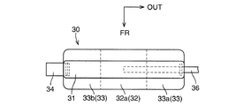
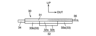
拘束装置30は、ラップベルト23部位に設けられる。拘束装置30は、図4、図5に示すように、ベルトガイド31と、内側エアバッグ32と、外側エアバッグ33と、ストラップ34と、インフレータ35(図1参照)と、インフレータガスチューブ36と、を備える。 The restraining device 30 is provided at the lap belt 23 site. 4 and 5, the restraining device 30 includes a belt guide 31, an inner airbag 32, an outer airbag 33, a strap 34, an inflator 35 (see FIG. 1), an inflator gas tube 36, .

ベルトガイド31は、ラップベルト23に支持されている。ベルトガイド31は、たとえば可撓性を有する伸縮不能な布製であり、乗員Pの体型によって異なるラップベルト23の形状に馴染めるようになっている。ベルトガイド31は、ラップベルト23よりも幅広とされている。ベルトガイド31は、ベルトガイド31にラップベルト23が挿通する図示略の孔を設けるなどにより、ラップベルト23に対してラップベルト23の長手方向(車幅方向)に可動(摺動可能)とされている。   The belt guide 31 is supported by the lap belt 23. The belt guide 31 is made of, for example, a flexible and non-stretchable cloth, and can be adapted to the shape of the lap belt 23 which varies depending on the body shape of the occupant P. The belt guide 31 is wider than the lap belt 23. The belt guide 31 is movable (slidable) in the longitudinal direction (vehicle width direction) of the lap belt 23 with respect to the lap belt 23 by providing a hole (not shown) through which the lap belt 23 is inserted in the belt guide 31. ing.

ベルトガイド31は、ラップベルト23の長手方向と異なる方向には、ラップベルト23に対して移動不能とされている。そのため、ベルトガイド31に設けられる内側エアバッグ32および外側エアバッグ33が、ラップベルト23に対して前後方向に動いてしまうことを抑制できる。 The belt guide 31 is immovable with respect to the lap belt 23 in a direction different from the longitudinal direction of the lap belt 23. Therefore, it is possible to prevent the inner airbag 32 and the outer airbag 33 provided on the belt guide 31 from moving in the front-rear direction with respect to the lap belt 23.

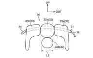
内側エアバッグ32は、ベルトガイド31に設けられている。内側エアバッグ32は、膨張展開していないとき全体がベルトガイド31内に格納されていてもよく、少なくとも一部がベルトガイド31から露出していてもよい。内側エアバッグ32は、図1に示すように、側突時に、ベルトガイド31から乗員Pの左右大腿部P1,P2間に膨張展開する。   The inner airbag 32 is provided on the belt guide 31. The inner airbag 32 may be entirely stored in the belt guide 31 when not inflated and deployed, or at least a part of the inner airbag 32 may be exposed from the belt guide 31. As shown in FIG. 1, the inner airbag 32 is inflated and deployed between the belt guide 31 and the left and right thighs P1 and P2 of the occupant P at the time of a side collision.

膨張展開状態における内側エアバッグ32の下端は、乗員Pの左右大腿部P1,P2の上下方向中央よりも下方に位置することが望ましい。この理由は、側突時に内側エアバッグ32を用いて反衝突側の大腿部P1もしくはP2を効果的に拘束できるようにするためである。また、膨張展開状態における内側エアバッグ32の上端は、乗員Pの左右大腿部P1,P2よりも上方に位置する。また、図2に示すように、膨張展開状態における内側エアバッグ32の後端は、乗員Pの腰前に位置するベルトガイド31部分よりも後方に位置している。また、膨張展開状態における内側エアバッグ32の前端は、ベルトガイド31よりも前方に位置している。
したがって、膨張展開状態にある内側エアバッグ32により、ベルトガイド31から乗員Pの左右大腿部P1,P2間にわたるスペースの略全体を埋めることができる。
It is desirable that the lower end of the inner airbag 32 in the inflated and deployed state is located below the center of the left and right thighs P1 and P2 of the occupant P in the vertical direction. This is because the thigh P1 or P2 on the anti-collision side can be effectively restrained by using the inner airbag 32 at the time of a side collision. Further, the upper end of the inner airbag 32 in the inflated and deployed state is located above the left and right thighs P1 and P2 of the occupant P. As shown in FIG. 2, the rear end of the inner airbag 32 in the inflated and deployed state is located behind the belt guide 31 portion located in front of the occupant P. Further, the front end of the inner airbag 32 in the inflated and deployed state is located in front of the belt guide 31.
Therefore, substantially the entire space from the belt guide 31 to the left and right thighs P1, P2 of the occupant P can be filled by the inner airbag 32 in the inflated and deployed state.

内側エアバッグ32は、図1に示すように、上側チャンバ32aと、膨張展開時に上側チャンバ32aよりも下側に位置する下側チャンバ32bと、を備える。両チャンバ32a、32bは、1つの袋体の上下中間部を縫製することで形成されていてもよく、互いに異なる2つの袋体にて形成されていてもよい。両チャンバ32a、32bは、互いに直接連通しあっている。 As shown in FIG. 1, the inner airbag 32 includes an upper chamber 32 a and a lower chamber 32 b positioned below the upper chamber 32 a when inflated and deployed. Both chambers 32a and 32b may be formed by sewing the upper and lower middle portions of one bag body, or may be formed by two different bag bodies. Both chambers 32a and 32b are in direct communication with each other.

外側エアバッグ33は、ベルトガイド31に設けられている。外側エアバッグ33は、膨張展開していないとき、全体がベルトガイド31内に格納されていてもよく、少なくとも一部がベルトガイド31から露出していてもよい。外側エアバッグ33は、内側エアバッグ32の左右両側に配置されており、膨張展開時、内側エアバッグ32の上側エアバッグ32aを左右両側から挟んでいる。 The outer airbag 33 is provided on the belt guide 31. When the outer airbag 33 is not inflated and deployed, the entire outer airbag 33 may be stored in the belt guide 31, or at least a part of the outer airbag 33 may be exposed from the belt guide 31. The outer airbag 33 is disposed on both the left and right sides of the inner airbag 32, and sandwiches the upper airbag 32a of the inner airbag 32 from both the left and right sides when inflated and deployed.

外側エアバッグ33は、膨張展開時、乗員Pの左右大腿部P1,P2の上面から外側面にわたって接触する。すなわち、外側エアバッグ33は、膨張展開時に車幅方向外側の大腿部P1の上面から外側面にわたって接触する車外側チャンバ33aと、膨張展開時に車幅方向内側の大腿部P2の上面から外側面にわたって接触する車内側チャンバ33bと、を備える。両チャンバ33a、33bは、1つの袋体の左右中間部を縫製することで形成されていてもよく、互いに異なる2つの袋体にて形成されていてもよい。両チャンバ33a、33bは、互いに直接連通しあっていてもよく、内側エアバッグ32の上側チャンバ32aを介して互いに連通していてもよい。 The outer airbag 33 contacts from the upper surface to the outer surface of the left and right thighs P1, P2 of the occupant P at the time of inflation and deployment. In other words, the outer airbag 33 is in contact with the outer side chamber 33a that is in contact with the outer surface from the upper surface of the thigh P1 on the outer side in the vehicle width direction when inflated and deployed, and the outer airbag 33 A vehicle interior chamber 33b that contacts the side surface. Both chambers 33a and 33b may be formed by sewing the left and right intermediate portions of one bag body, or may be formed by two different bag bodies. Both the chambers 33 a and 33 b may be in direct communication with each other, or may be in communication with each other via the upper chamber 32 a of the inner airbag 32.

両チャンバ33a、33bの、左右大腿部P1,P2の両外側に位置する部分の下端は、左右大腿部P1,P2の上下方向中央よりも下方に位置することが望ましい。この理由は、(i)側突時に外側エアバッグ33を用いて衝突側の大腿部P1もしくはP2を効果的に拘束できるようにするためである。また、(ii)外側エアバッグ33が乗員Pの左右大腿部P1,P2に対して左右にずれることを抑制でき、外側エアバッグ33に挟まれる内側エアバッグ32が乗員Pの大腿部P1,P2に対して左右にずれることを抑制でき、内側エアバッグ32を確実に乗員Pの大腿部P1,P2間に膨張展開させることができるからである。 It is desirable that the lower ends of the portions of both chambers 33a and 33b located on both outer sides of the left and right thighs P1 and P2 are positioned below the vertical center of the left and right thighs P1 and P2. This is because (i) the thigh P1 or P2 on the collision side can be effectively restrained by using the outer airbag 33 at the time of a side collision. Further, (ii) the outer airbag 33 can be prevented from shifting to the left and right with respect to the left and right thighs P1, P2 of the occupant P, and the inner airbag 32 sandwiched between the outer airbags 33 is the thigh P1 of the occupant P. , P2 can be prevented from shifting to the left and right, and the inner airbag 32 can be reliably inflated and deployed between the thighs P1, P2 of the occupant P.

内外エアバッグ32,33の全体の、膨張展開時における幅(車幅方向長さ)L1(図6参照)は、成人男性(AM50(American Maleを100人並べたときの小柄な方から50番目))の腰部重心高さでの腰幅以上とされている。望ましくは、幅L1は、AM95の腰部重心高さでの腰幅以上とされている。この理由は、乗員Pが大柄な男性であっても、外側エアバッグ33が左右大腿部P1,P2の両外側にまわり込むことができるようにするためである。また、内側エアバッグ32の下側チャンバ32bの、膨張展開時における幅(車幅方向長さ)L2(図7参照)は、成人女性(AF05(American Femaleを100人並べたときの小柄な方から5番目))の左右の大腿骨中心間距離以上とされている。この理由は、乗員Pが小柄な女性であっても、左右大腿部P1,P2と下側チャンバ32bとの間に隙間ができることを抑制するためである。 The width (length in the vehicle width direction) L1 (see FIG. 6) of the entire inner and outer airbags 32 and 33 when inflated and deployed is 50th from the smaller one when 100 American Males are arranged (AM50). )) Waist width at the waist center of gravity height. Desirably, the width L1 is equal to or greater than the waist width at the waist center of gravity height of AM95. The reason is that even if the occupant P is a large man, the outer airbag 33 can go around both the left and right thighs P1, P2. In addition, the width (length in the vehicle width direction) L2 (see FIG. 7) of the lower chamber 32b of the inner airbag 32 at the time of inflating and deploying is an adult female (smaller one when 100 American Women are lined up. 5) from the center of the left and right femur centers. The reason for this is to prevent a gap from being formed between the left and right thighs P1, P2 and the lower chamber 32b even if the occupant P is a small woman.

ストラップ34は、たとえば可撓性を有する伸縮不能な布製である。ストラップ34は、一端部でタングプレート28に取付けられており、図4に示すように、他端部でベルトガイド31に取付けられている。タングプレート28はバックル27に係合しており乗員Pの体型によらず一定位置にあるため、タングプレート28とベルトガイド31を繋ぐストラップ34により、乗員Pに対するベルトガイド31の車幅方向位置を略一定に定めることができる。   The strap 34 is made of a non-stretchable cloth having flexibility, for example. The strap 34 is attached to the tongue plate 28 at one end, and is attached to the belt guide 31 at the other end as shown in FIG. Since the tongue plate 28 is engaged with the buckle 27 and is in a fixed position regardless of the body shape of the occupant P, the position of the belt guide 31 in the vehicle width direction with respect to the occupant P is determined by the strap 34 that connects the tongue plate 28 and the belt guide 31. It can be set substantially constant.

ストラップ34の少なくともベルトガイド31側端部は、図6に示すように、二股形状に分かれてその片方が内外エアバッグ32,33の少なくともいずれか1つの前端部に取付けられていてもよい。この場合、ストラップ34が取付けられる内外エアバッグ32,33の前端部を、ストラップ34により下方に大腿部P1,P2側に押し付けることができ、内外エアバッグ32,33による大腿部拘束効果を高めることができる。   As shown in FIG. 6, at least the end of the strap 34 on the side of the belt guide 31 may be divided into a bifurcated shape, and one of the ends may be attached to at least one front end of the inner and outer airbags 32 and 33. In this case, the front end portions of the inner and outer airbags 32 and 33 to which the strap 34 is attached can be pressed downward to the thigh P1 and P2 side by the strap 34, and the thigh restraint effect by the inner and outer airbags 32 and 33 can be obtained. Can be increased.

インフレータ35は、側突時に、図示略の側突検知センサが側突を検知し、側突判定用の図示略のECU(Electronic Control Unit、電子制御装置)からの信号が送られてきたとき、化学反応によりガスを発生して内外エアバッグ32,33にガスを供給する。インフレータ35は、図1に示すように、シート1に着座している乗員Pがインフレータ35に当たることを抑制するために、たとえばシートクッション1aの下面等に設置されている。なお、このインフレータ35は、シートクッション1aに図示略のクッションエアバッグが設けられている場合には、クッションエアバッグ用のインフレータと併用されていてもよい。内外エアバッグ32,33は側突時に膨張展開するものであり、クッションエアバッグは前突時に膨張展開するものであるため、インフレータを併用可能である。   In the inflator 35, when a side collision is detected, a side collision detection sensor (not shown) detects a side collision, and when a signal from an ECU (Electronic Control Unit, not shown) for side collision determination is sent, Gas is generated by a chemical reaction and supplied to the inner and outer airbags 32 and 33. As shown in FIG. 1, the inflator 35 is installed, for example, on the lower surface of the seat cushion 1 a in order to prevent the occupant P sitting on the seat 1 from hitting the inflator 35. The inflator 35 may be used in combination with an inflator for a cushion airbag when a cushion airbag (not shown) is provided on the seat cushion 1a. Since the inner and outer airbags 32 and 33 are inflated and deployed at the time of a side impact, and the cushion airbag is inflated and deployed at the time of a front impact, an inflator can be used in combination.

インフレータガスチューブ36は、インフレータ35からのガスを内外エアバッグ32,33に供給するために設けられる、インフレータガスチューブ36は、複数設けられて内側エアバッグ32の2つのチャンバ32a、32bと外側エアバッグ33の2つのチャンバ33a、33bのそれぞれに挿入されていてもよいが、部品点数低減のため、1つのみ設けられていることが望ましい。インフレータガスチューブ36が1つのみ設けられる場合、インフレータガスチューブ36は、図5に示すように、内側エアバッグ32の上側チャンバ32aに挿入されることが望ましい。この理由は、プリテンショナ24aの作動によりシートベルト20による乗員Pの拘束開始が早められている場合、4つのチャンバ32a、32b、33a、33bのうち最も早く膨張展開スペースが無くなっていくのが上側チャンバ32aであるため、上側チャンバ32aを最初に膨張展開させることが望ましいからである。   The inflator gas tube 36 is provided to supply gas from the inflator 35 to the inner and outer airbags 32 and 33. A plurality of inflator gas tubes 36 are provided, and the two chambers 32a and 32b of the inner airbag 32 and the outer air are provided. Although it may be inserted into each of the two chambers 33a, 33b of the bag 33, it is desirable that only one is provided to reduce the number of parts. When only one inflator gas tube 36 is provided, the inflator gas tube 36 is preferably inserted into the upper chamber 32a of the inner airbag 32 as shown in FIG. The reason for this is that when the restraint start of the occupant P by the seat belt 20 is accelerated by the operation of the pretensioner 24a, the expansion and deployment space disappears first among the four chambers 32a, 32b, 33a, 33b. This is because the upper chamber 32a is preferably inflated and deployed first because it is the chamber 32a.

インフレータ35からガスが供給されたときにおける、内外エアバッグ32,33の膨張展開順序は、図8に示すように、次のとおりである。なお、図8における白矢印は、ガス流れの向きを示している。
(i)先ず、図8(a)、(b)に示すように、インフレータガスチューブ36を通ってきたガスにより、内側エアバッグ32の上側チャンバ32aが膨張展開し始める。すなわち、内側エアバッグ32が外側エアバッグ33に先行して膨張展開し始める。
(ii)内側エアバッグ32の上側チャンバ32aの内圧が高まってくると、可変ベントホール構造等により、図8(b)、(c)に示すように、上側チャンバ32aから外側エアバッグ33の車外側および車内側の両チャンバ33a、33bにガスが流れ始め、外側エアバッグ33の両チャンバ33a、33bが膨張展開し始める。
(iii)内側エアバッグ32の上側チャンバ32aと外側エアバッグ33の車外側および車内側の両チャンバ33a、33bの内圧が高まってくると、可変ベントホール構造等により、図8(d)に示すように、内側エアバッグ32の上側チャンバ32aから下側チャンバ32bにガスが流れ始め、下側チャンバ32bが膨張展開し始める。
(iv)内側エアバッグ32の上下両チャンバ32a、32bと、外側エアバッグ33の車外側および車内側の両チャンバ33a、33bの全ての内圧が高まったとき、内外エアバッグ32,33の膨張展開が完了する。
As shown in FIG. 8, the order of inflation and deployment of the inner and outer airbags 32 and 33 when gas is supplied from the inflator 35 is as follows. In addition, the white arrow in FIG. 8 has shown the direction of the gas flow.
(I) First, as shown in FIGS. 8A and 8B, the upper chamber 32a of the inner airbag 32 starts to be inflated and deployed by the gas that has passed through the inflator gas tube. That is, the inner airbag 32 starts to inflate and deploy before the outer airbag 33.
(Ii) When the internal pressure of the upper chamber 32a of the inner airbag 32 increases, the vehicle of the outer airbag 33 is moved from the upper chamber 32a by the variable vent hole structure or the like as shown in FIGS. Gas begins to flow into both the outer and inner chambers 33a, 33b, and both the chambers 33a, 33b of the outer airbag 33 begin to inflate and deploy.
(Iii) When the internal pressures of the upper chamber 32a of the inner airbag 32 and the outer and inner chambers 33a, 33b of the outer airbag 33 are increased, a variable venthole structure or the like is shown in FIG. As described above, gas starts to flow from the upper chamber 32a of the inner airbag 32 to the lower chamber 32b, and the lower chamber 32b starts to expand and deploy.
(Iv) When the inner pressures of the upper and lower chambers 32a and 32b of the inner airbag 32 and the outer and inner chambers 33a and 33b of the outer airbag 33 are all increased, the inner and outer airbags 32 and 33 are inflated and deployed. Is completed.

内側エアバッグ32の上側チャンバ32aと、外側エアバッグ33の車外側および車内側の両チャンバ33a、33bの膨張展開は、プリテンショナ24aの作動によりラップベルト23が乗員Pを押さえつける荷重が最大となる前に完了している。内側エアバッグ32の下側チャンバ32bの膨張展開は、プリテンショナ24aの作動によりラップベルト23が乗員Pを押さえつける荷重が最大となる前に完了していてもよく完了していなくてもよい。これは、下側チャンバ32bの膨張展開スペース(上側チャンバ32aの下方かつ左右大腿部P1,P2間)は、プリテンショナ24aの作動状態によらずに存在すると考えられるからである。 In the expansion and deployment of the upper chamber 32a of the inner airbag 32 and the outer and inner chambers 33a and 33b of the outer airbag 33, the load by which the lap belt 23 presses the occupant P by the operation of the pretensioner 24a is maximized. Has been completed before. The expansion and deployment of the lower chamber 32b of the inner airbag 32 may or may not be completed before the load that the lap belt 23 presses the occupant P is maximized by the operation of the pretensioner 24a. This is because the expansion / decompression space of the lower chamber 32b (below the upper chamber 32a and between the left and right thighs P1 and P2) is considered to exist regardless of the operating state of the pretensioner 24a.

つぎに、本発明実施例の作用、効果を説明する。   Next, the operation and effect of the embodiment of the present invention will be described.

(A)大腿部拘束装置30が、ラップベルト23に支持されるベルトガイド31と、側突時にベルトガイド31から乗員Pの左右大腿部P1,P2間に膨張展開する内側エアバッグ32と、を備えるため、内側エアバッグ32を用いて側突時に反衝突側の大腿部P1もしくはP2を拘束できる。この結果、乗員Pへ入力する荷重を反衝突側の大腿部にも受け持たせることができ、乗員腰部へ入力する荷重を従来に比べて低減できる。
詳しくは、プリテンショナ機能が働いてシートベルト20のみで乗員Pを拘束する側突初期にラップベルト23から乗員Pに入力される荷重を、従来に比べて増やすことができる。このため、変形してきたドアトリムが乗員Pに当たり乗員Pを拘束する側突後期に乗員Pに入力される荷重を、減らすことができる。
(A) The thigh restraint device 30 includes a belt guide 31 supported by the lap belt 23, and an inner airbag 32 that inflates and deploys between the belt guide 31 and the left and right thighs P1 and P2 of the occupant P at the time of a side collision. Therefore, the thigh P1 or P2 on the anti-collision side can be restrained at the time of a side collision using the inner airbag 32. As a result, the load input to the occupant P can be applied to the thigh on the anti-collision side, and the load input to the occupant waist can be reduced as compared with the conventional case.
Specifically, the load input from the lap belt 23 to the occupant P at the initial stage of the side collision in which the pretensioner function operates and the occupant P is restrained only by the seat belt 20 can be increased as compared with the conventional case. For this reason, it is possible to reduce the load input to the occupant P in the late stage of the side collision in which the deformed door trim hits the occupant P and restrains the occupant P.

(B)大腿部拘束装置30が、内側エアバッグ32の左右両側に配置され膨張展開時に乗員Pの大腿部P1,P2の上面から外側面にわたって接触する外側エアバッグ33を備えるため、内側エアバッグ32を用いて反衝突側の大腿部P1もしくはP2を拘束するだけでなく外側エアバッグ33を用いて衝突側の大腿部P1もしくはP2も拘束できる。よって、外側エアバッグ33が設けられていない場合に比べて、乗員腰部へ入力する荷重をさらに低減できる。 (B) Since the thigh restraint device 30 includes the outer airbag 33 that is disposed on both the left and right sides of the inner airbag 32 and contacts the upper surface of the thigh P1, P2 of the occupant P from the upper surface to the outer surface when inflated and deployed. In addition to restraining the anti-collision thigh P1 or P2 using the airbag 32, the outer airbag 33 can be used to restrain the thigh P1 or P2 on the collision side. Therefore, compared with the case where the outer side airbag 33 is not provided, the load input into a passenger | crew waist | hip | lumbar part can further be reduced.

(C)大腿部拘束装置30が外側エアバッグ33を備えており、外側エアバッグ33が膨張展開時に乗員Pの左右大腿部P1,P2の上面から外側面にわたって接触するため、外側エアバッグ33が左右大腿部P1,P2に対して左右にずれることを抑制できる。よって、外側エアバッグ33に挟まれる内側エアバッグが左右大腿部P1,P2に対して左右にずれることを抑制できる。 (C) Since the thigh restraint device 30 includes the outer airbag 33 and the outer airbag 33 contacts the outer surface from the upper surfaces of the left and right thighs P1 and P2 of the occupant P during inflation and deployment, the outer airbag 33 can be prevented from shifting to the left and right with respect to the left and right thighs P1 and P2. Therefore, it is possible to suppress the inner airbag sandwiched between the outer airbags 33 from shifting to the left and right with respect to the left and right thighs P1 and P2.

(D)内側エアバッグ32が外側エアバッグ33に先行して膨張展開を開始するため、プリテンショナ24bの作動によりシートベルト20による乗員Pの拘束開始が早められている場合であっても、内側エアバッグ32を確実に乗員Pの左右大腿部P1,P2間に膨張展開させることができる。 (D) Since the inner airbag 32 starts inflating and deploying prior to the outer airbag 33, even if the restraint start of the occupant P by the seat belt 20 is accelerated by the operation of the pretensioner 24b, The airbag 32 can be surely inflated and deployed between the left and right thighs P1, P2 of the occupant P.

(E)ベルトガイド31が、ラップベルト23に対してラップベルト23の長手方向に可動に設けられているため、乗員Pの体型に合わせてベルトガイド31をラップベルト23に対して移動させることができる。そのため、乗員Pの体型によらずに内側エアバッグ32を乗員Pの左右大腿部P1,P2間に膨張展開させることができる。 (E) Since the belt guide 31 is movably provided in the longitudinal direction of the lap belt 23 with respect to the lap belt 23, the belt guide 31 can be moved with respect to the lap belt 23 according to the body shape of the occupant P. it can. Therefore, the inner airbag 32 can be inflated and deployed between the left and right thighs P1, P2 of the occupant P regardless of the body shape of the occupant P.

(F)大腿部拘束装置30が、タングプレート28とベルトガイド31とを繋ぐストラップ34を備えるため、内外エアバッグ32,33が膨張展開していないときにベルトガイド31が乗員Pに対して車両外側へずれる量を抑制でき、内側エアバッグ32を乗員Pの大腿部P1,P2間に確実に膨張展開させることができる。 (F) Since the thigh restraint device 30 includes the strap 34 that connects the tongue plate 28 and the belt guide 31, the belt guide 31 is positioned against the occupant P when the inner and outer airbags 32 and 33 are not inflated and deployed. The amount of deviation to the vehicle outer side can be suppressed, and the inner airbag 32 can be reliably inflated and deployed between the thighs P1 and P2 of the occupant P.

(G)本発明によれば、上記(A)〜(F)に加えて、さらにつぎの作用、効果を得ることができる。
(G1)ベルトガイド31が設けられており、ベルトガイド31がラップベルト23よりも幅広とされているため、ラップベルト23と乗員Pとの接触面積よりもベルトガイド31と乗員Pとの接触面積が増加され、前突時においてラップベルト23から乗員Pにかかる荷重を分散できる。
(G2)内側エバッグ32および外側エアバッグ33が設けられているため、ラップベルト23と乗員Pとの接触面積よりも内外エアバッグ32,33と乗員Pとの接触面積を増加させることができ、前突時においてラップベルト23から乗員Pにかかる荷重を分散できる。
(G) According to the present invention, the following actions and effects can be obtained in addition to the above (A) to (F).
(G1) Since the belt guide 31 is provided and the belt guide 31 is wider than the lap belt 23, the contact area between the belt guide 31 and the occupant P is greater than the contact area between the lap belt 23 and the occupant P. The load applied to the occupant P from the lap belt 23 at the time of the front collision can be dispersed.
(G2) Since the inner airbag 32 and the outer airbag 33 are provided, the contact area between the inner and outer airbags 32 and 33 and the occupant P can be increased more than the contact area between the lap belt 23 and the occupant P. The load applied to the occupant P from the lap belt 23 during the front collision can be dispersed.

1 シート
2 ピラー
1a シートクッション
1b シートバック
1c ヘッドレスト
10 側面衝突用乗員保護装置
20 シートベルト
21 ウエビング
22 ショルダベルト
23 ラップベルト
24 リトラクタ
24a プリテンショナ
25 ラップアウターアンカ
26 スリップジョイント
27 バックル
28 タングプレート
30 大腿部拘束装置
31 ベルトガイド
32 内側エアバッグ
32a 上側チャンバ
32b 下側チャンバ
33 外側エアバッグ
33a 車外側チャンバ
33b 車内側チャンバ
34 ストラップ
35 インフレータ
36 インフレータガスチューブ
P 乗員
P1、P2 左右大腿部
DESCRIPTION OF SYMBOLS 1 Seat 2 Pillar 1a Seat cushion 1b Seat back 1c Headrest 10 Side collision passenger protection device 20 Seat belt 21 Webbing 22 Shoulder belt 23 Lap belt 24 Retractor 24a Pretensioner 25 Lap outer anchor 26 Slip joint 27 Buckle 28 Tang plate 30 Thigh Part restraint device 31 Belt guide 32 Inner airbag 32a Upper chamber 32b Lower chamber 33 Outer airbag 33a Outer chamber 33b Inboard chamber 34 Strap 35 Inflator 36 Inflator gas tube P Crew P1, P2 Left and right thighs

Claims (4)

タングプレートをバックルに係合してベルト装着したときにラップベルトを備えるシートベルトと、
前記ラップベルトに支持されるベルトガイドおよび側突時に該ベルトガイドから乗員の左右大腿部間に膨張展開する内側エアバッグを備える大腿部拘束装置と、
を有する側面衝突用乗員保護装置。
A seat belt provided with a lap belt when the tongue plate is engaged with the buckle and the belt is mounted;
A thigh restraint device comprising a belt guide supported by the lap belt and an inner airbag that inflates and deploys between the left and right thighs of the occupant from the belt guide in a side collision;
A side collision occupant protection device.
前記大腿部拘束装置は、さらに、前記内側エアバッグの左右両側に配置され膨張展開時に乗員の大腿部の上面から外側面にわたって接触する外側エアバッグを備える、請求項1記載の側面衝突用乗員保護装置。   2. The side collision according to claim 1, wherein the thigh restraint device further includes an outer airbag that is disposed on both left and right sides of the inner airbag and that contacts the outer surface of the occupant from the upper surface to the outer surface when inflated and deployed. Crew protection device. 前記内側エアバッグが前記外側エアバッグに先行して膨張展開を開始する請求項2記載の側面衝突用乗員保護装置。   The side collision occupant protection device according to claim 2, wherein the inner airbag starts inflating and deploying prior to the outer airbag. 前記ベルトガイドは、前記ラップベルトに対して該ラップベルトの長手方向に可動に設けられており、
前記大腿部拘束装置は、さらに、前記タングプレートと前記ベルトガイドとを繋ぐストラップを備える、請求項1〜請求項3のいずれか1項に記載の側面衝突用乗員保護装置。
The belt guide is provided movably in the longitudinal direction of the lap belt with respect to the lap belt,
The occupant protection device for side collision according to any one of claims 1 to 3, wherein the thigh restraint device further includes a strap that connects the tongue plate and the belt guide.
JP2013071826A 2013-03-29 2013-03-29 Side crash passenger protector Pending JP2014196014A (en)

Priority Applications (1)

Application Number Priority Date Filing Date Title
JP2013071826A JP2014196014A (en) 2013-03-29 2013-03-29 Side crash passenger protector

Applications Claiming Priority (1)

Application Number Priority Date Filing Date Title
JP2013071826A JP2014196014A (en) 2013-03-29 2013-03-29 Side crash passenger protector

Publications (1)

Publication Number Publication Date
JP2014196014A true JP2014196014A (en) 2014-10-16

Family

ID=52357189

Family Applications (1)

Application Number Title Priority Date Filing Date
JP2013071826A Pending JP2014196014A (en) 2013-03-29 2013-03-29 Side crash passenger protector

Country Status (1)

Country Link
JP (1) JP2014196014A (en)

Cited By (4)

* Cited by examiner, † Cited by third party
Publication number Priority date Publication date Assignee Title
JP2018161975A (en) * 2017-03-27 2018-10-18 株式会社Subaru Occupant protection device
JP2019172039A (en) * 2018-03-28 2019-10-10 株式会社Subaru Occupant restraint device
JP2021054250A (en) * 2019-09-30 2021-04-08 豊田合成株式会社 Crewman protection device
JP2021054251A (en) * 2019-09-30 2021-04-08 豊田合成株式会社 Crewman protection device

Cited By (9)

* Cited by examiner, † Cited by third party
Publication number Priority date Publication date Assignee Title
JP2018161975A (en) * 2017-03-27 2018-10-18 株式会社Subaru Occupant protection device
US10589706B2 (en) 2017-03-27 2020-03-17 Subaru Corporation Occupant protection device
JP2019172039A (en) * 2018-03-28 2019-10-10 株式会社Subaru Occupant restraint device
JP7032196B2 (en) 2018-03-28 2022-03-08 株式会社Subaru Crew restraint device
JP2021054250A (en) * 2019-09-30 2021-04-08 豊田合成株式会社 Crewman protection device
JP2021054251A (en) * 2019-09-30 2021-04-08 豊田合成株式会社 Crewman protection device
US11524648B2 (en) 2019-09-30 2022-12-13 Toyoda Gosei Co., Ltd. Occupant protection system
JP7223335B2 (en) 2019-09-30 2023-02-16 豊田合成株式会社 passenger protection device
JP7223336B2 (en) 2019-09-30 2023-02-16 豊田合成株式会社 passenger protection device

Similar Documents

Publication Publication Date Title
CN107848483B (en) Driver and passenger protection device
JP5999061B2 (en) Seat-mounted airbag device and vehicle seat
US8104790B2 (en) Vehicular occupant restraint system
US20200238944A1 (en) Airbag Assembly for a Vehicle Seat of a Motor Vehicle
JP4453480B2 (en) Occupant protection device and occupant protection method
JP2008184159A (en) Occupant crash protection device
JP2005239055A (en) Occupant crash protection device
JP2019018736A (en) Vehicle seat equipped with side airbag device
JP5907135B2 (en) Side airbag device for vehicle
WO2015098369A1 (en) Air belt and air belt device
JP2008007036A (en) Occupant crash protection device
EP1950105B1 (en) Occupant restraint system
JP2009018715A (en) Side airbag device
JP2014196014A (en) Side crash passenger protector
CN111688624B (en) Airbag device
JP6729454B2 (en) Airbag system
JP2008296722A (en) Occupant protection device
KR20220075368A (en) Airbag device and vehicle seat
JP4792935B2 (en) Crew restraint system
JP6499093B2 (en) Crew protection device
JP4946444B2 (en) Crew protection device
JP2019111916A (en) Vehicle side airbag device
JP2008143273A (en) Vehicular occupant crash protector
CN116323332A (en) Occupant protection device
JP2022110958A (en) Vehicular side airbag device