JP2014192560A - Portable terminal and assembly method of the same - Google Patents

Portable terminal and assembly method of the same Download PDF

Info

Publication number
JP2014192560A
JP2014192560A JP2013063961A JP2013063961A JP2014192560A JP 2014192560 A JP2014192560 A JP 2014192560A JP 2013063961 A JP2013063961 A JP 2013063961A JP 2013063961 A JP2013063961 A JP 2013063961A JP 2014192560 A JP2014192560 A JP 2014192560A
Authority
JP
Japan
Prior art keywords
opening
housing
portable terminal
sheet
circuit board
Prior art date
Legal status (The legal status is an assumption and is not a legal conclusion. Google has not performed a legal analysis and makes no representation as to the accuracy of the status listed.)
Pending
Application number
JP2013063961A
Other languages
Japanese (ja)
Inventor
Takahisa Osawa
貴久 大澤
Yotaro Noda
陽太郎 野田
Current Assignee (The listed assignees may be inaccurate. Google has not performed a legal analysis and makes no representation or warranty as to the accuracy of the list.)
NEC Platforms Ltd
NEC Casio Mobile Communications Ltd
Original Assignee
NEC AccessTechnica Ltd
NEC Casio Mobile Communications Ltd
Priority date (The priority date is an assumption and is not a legal conclusion. Google has not performed a legal analysis and makes no representation as to the accuracy of the date listed.)
Filing date
Publication date
Application filed by NEC AccessTechnica Ltd, NEC Casio Mobile Communications Ltd filed Critical NEC AccessTechnica Ltd
Priority to JP2013063961A priority Critical patent/JP2014192560A/en
Publication of JP2014192560A publication Critical patent/JP2014192560A/en
Pending legal-status Critical Current

Links

Images

Abstract

PROBLEM TO BE SOLVED: To solve a problem that it is difficult to realize a stable waterproof function in a portable terminal because of a lot of design limitations.SOLUTION: A portable terminal includes: a housing member which is formed including a sheet metal and a resin and has multiple openings; a circuit board which is inserted so as to be positioned in at least a first opening of the multiple openings and is fixed thereto; and a sheet-like member which is bonded so as to close the first opening.

Description

本発明は、携帯端末及び携帯端末の組立方法に関し、特に、防水構造を備えた携帯端末及び携帯端末の組立方法に関する。   The present invention relates to a mobile terminal and a mobile terminal assembly method, and more particularly, to a mobile terminal having a waterproof structure and a mobile terminal assembly method.

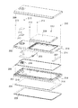
携帯端末が広く用いられるにつれて、その活用場面も広がっており、その防水性能の向上も求められている。背景技術による携帯端末の防水構造について、図面を参照しながら説明する。図7は、関連する防水携帯端末の概略部品構成を示した分解斜視図である。   As mobile terminals are widely used, their usage scenes are expanding, and improvement in waterproof performance is also demanded. A waterproof structure of a portable terminal according to the background art will be described with reference to the drawings. FIG. 7 is an exploded perspective view showing a schematic component configuration of a related waterproof portable terminal.

図7において、上筐体201と下筐体202はパッキン203を挟み、防水携帯端末筐体の主要骨格を形成している。また液晶等の表示デバイス204、回路基板205、電池206、通信用アンテナ207を筐体の内部に組み込んでいる。透明スクリーン208及び電池カバー209を、防水機能を有した適切な形状で上筐体201及び下筐体202に組み込んで、機器の外装を構成している。また、カメラ210等のデバイス部品の実装のために開いた下筐体202の開口部は、防水両面テープ211を備えたカメラスクリーン212にて止水されている。   In FIG. 7, an upper housing 201 and a lower housing 202 sandwich a packing 203 and form a main skeleton of a waterproof portable terminal housing. A display device 204 such as a liquid crystal, a circuit board 205, a battery 206, and a communication antenna 207 are incorporated in the housing. The transparent screen 208 and the battery cover 209 are incorporated into the upper casing 201 and the lower casing 202 in an appropriate shape having a waterproof function to constitute the exterior of the device. The opening of the lower housing 202 opened for mounting device parts such as the camera 210 is stopped by a camera screen 212 having a waterproof double-sided tape 211.

図7ではさらにパッキン203を挟んだ状態で、ネジ213及び相対する嵌合爪214にて上筐体201と下筐体202とを固定している。さらに、防水携帯端末を設計する上での、一般的な設計課題について記述する。図7において、上筐体201に着目する。機器の使用状態を考慮し、適切な剛性を確保することは、不用意な落下等の外力に耐える機器の信頼性を向上する重要な設計課題である。そのため、上筐体201は金属製の板215を一体成形したプラスチック成形部品としている。   In FIG. 7, the upper housing 201 and the lower housing 202 are fixed by screws 213 and the opposing fitting claws 214 with the packing 203 interposed therebetween. Furthermore, general design issues in designing waterproof portable terminals are described. In FIG. 7, attention is focused on the upper housing 201. It is an important design issue to improve the reliability of a device that can withstand external forces such as inadvertent dropping, and to ensure appropriate rigidity in consideration of the use state of the device. Therefore, the upper housing 201 is a plastic molded part in which a metal plate 215 is integrally molded.

次に、図7において、内部構成部品の配置に着目する。回路基板205、電池206、通信用アンテナ207が同図に示すような配列で配置されていることは一般的な構成である。重量物である電池206を機器の中心に置き、重心を機器の中央に配置している。通信アンテナ207は音声通話時に人体が電波にさらされたときの比吸収率(SAR:Specific Absorption Rate)を考慮して、機器の側面に配置している。これらの、設計制約を受けながら、安定した防水機能を実現し、デザイン的にも優れた防水携帯端末を設計することが課題である。   Next, in FIG. 7, attention is paid to the arrangement of internal components. It is a general configuration that the circuit board 205, the battery 206, and the communication antenna 207 are arranged in an arrangement as shown in FIG. A heavy battery 206 is placed at the center of the device, and the center of gravity is placed at the center of the device. The communication antenna 207 is arranged on the side of the device in consideration of a specific absorption rate (SAR) when the human body is exposed to radio waves during a voice call. It is an issue to design a waterproof portable terminal that realizes a stable waterproof function and is excellent in design while receiving design constraints.

特開2012−95132号公報JP 2012-95132 A

携帯端末の防水性能は、より高いほうが好ましい。しかしながら、図7に示される関連する携帯端末では、上筐体201と下筐体202とでパッキン203を挟む設計となっている。そのため、適切な寸法で構成を実現させなければ、機器の防水機能が損なわれる可能性がある。それぞれの部品寸法ばらつきに加え、パッキン203を潰した反力を受けた上筐体201や下筐体202の変形を抑えることは重要な設計課題である。装置内部の実装部品、装置サイズ、装置デザインのそれぞれの制約を受けるため、上筐体201と下筐体202をパッキン203の全周に渡る確実な固定を実現することは、防水携帯端末を設計する際の大きな課題となっている。   It is preferable that the waterproof performance of the portable terminal is higher. However, the related portable terminal shown in FIG. 7 is designed such that the packing 203 is sandwiched between the upper casing 201 and the lower casing 202. Therefore, if the configuration is not realized with appropriate dimensions, the waterproof function of the device may be impaired. It is an important design problem to suppress the deformation of the upper casing 201 and the lower casing 202 that are subjected to the reaction force of crushing the packing 203 in addition to the variation in the size of each part. In order to be sure to fix the upper housing 201 and the lower housing 202 over the entire circumference of the packing 203, the waterproof portable terminal is designed in order to be restricted by the mounting parts inside the device, the device size, and the device design. It has become a big challenge when doing.

また、図7に示される関連する携帯端末では、上筐体201と下筐体202とでパッキン203を挟む設計となっており、上筐体201と下筐体202との間に、回路基板205、通信アンテナ207やカメラ210等のデバイス部品を挟む配置となっている。このため、携帯端末の組立作業が複雑になり、防水機能維持のための確実な組立作業を慎重に行なう必要がある。   In the related portable terminal shown in FIG. 7, the packing 203 is sandwiched between the upper casing 201 and the lower casing 202, and the circuit board is interposed between the upper casing 201 and the lower casing 202. 205, and device parts such as the communication antenna 207 and the camera 210 are arranged therebetween. For this reason, the assembling work of the portable terminal becomes complicated, and it is necessary to carefully perform the assembling work for maintaining the waterproof function.

一方、特許文献1では上部筐体と下部筐体の間にゴムパッキング等を挟み込まない形態の、携帯電子機器の防水構造が提案されている。特許文献1では、携帯電子機器の筐体の上面開口を通して内部実装部品を挿入して実装し、その後にシート状部材で上面開口を覆蓋することにより、部品点数低減による組立工数の低減と携帯電子機器の防水性能向上とを両立させている。   On the other hand, Patent Document 1 proposes a waterproof structure for a portable electronic device in which rubber packing or the like is not sandwiched between an upper housing and a lower housing. In Patent Document 1, an internal mounting component is inserted and mounted through an upper surface opening of a casing of a portable electronic device, and then the upper surface opening is covered with a sheet-like member, thereby reducing the assembly man-hour by reducing the number of components and the portable electronic device. It is compatible with improving the waterproof performance of the equipment.

特許文献1で提案された携帯電子機器では、防水性能を向上させることが可能であるが、さらなる防水性能の向上が望まれている。また、特許文献1で提案された携帯電子機器とは異なる内部構造による、組立作業の円滑化と防水性能の向上との両立が望まれる。   In the portable electronic device proposed in Patent Document 1, it is possible to improve the waterproof performance, but further improvement of the waterproof performance is desired. Also, it is desired to achieve both smooth assembly work and improved waterproof performance by an internal structure different from the portable electronic device proposed in Patent Document 1.

このように、関連する携帯端末においては、設計上の制約が多いため、安定した防水機能を実現することが困難である、という問題があった。   As described above, the related portable terminal has a problem that it is difficult to realize a stable waterproof function because of many design restrictions.

本発明の目的は、上述した課題である、携帯端末においては、設計上の制約が多いため、安定した防水機能を実現することが困難である、という課題を解決する携帯端末及び携帯端末の組立方法を提供することにある。   An object of the present invention is to assemble a portable terminal and a portable terminal that solve the problem that it is difficult to realize a stable waterproof function because there are many design restrictions in the portable terminal. It is to provide a method.

前記目的を達成するため、本発明に係る携帯端末は、板金と樹脂とを含んでなり、複数の開口部を有する筐体部材と、上記複数の開口部のうちの少なくとも第1開口部に配置するよう挿入されて固定された回路基板と、上記第1開口部を塞ぐように貼り付けられたシート状部材とを有する。   In order to achieve the above object, a portable terminal according to the present invention includes a sheet metal and a resin, and is disposed in a housing member having a plurality of openings and at least a first opening of the plurality of openings. A circuit board that is inserted and fixed to be fixed, and a sheet-like member that is attached so as to close the first opening.

本発明に係る携帯端末の組立方法は、板金と樹脂とを含んでなり、一主表面に第1開口部を有する筐体部材と、上記第1開口部に位置するよう固定された回路基板と、上記第1開口部を塞ぐように貼り付けられたシート状部材とを有する携帯端末の組立方法であって、
上記回路基板を第2開口部を用いて上記第1開口部に配置し固定した後に、上記筐体部材の上記第1開口部を塞ぐように上記シート状部材を接着テープを介して貼り付ける。
A method for assembling a portable terminal according to the present invention includes a housing member having a first opening on one main surface, comprising a sheet metal and a resin, and a circuit board fixed so as to be positioned in the first opening. A method of assembling a portable terminal having a sheet-like member attached so as to close the first opening,
After the circuit board is arranged and fixed in the first opening using the second opening, the sheet-like member is attached via an adhesive tape so as to close the first opening of the housing member.

本発明の携帯端末及び携帯端末の組立方法によれば、設計上の制約が多い場合であっても安定した防水機能を実現することができる。   According to the mobile terminal and the mobile terminal assembly method of the present invention, a stable waterproof function can be realized even when there are many design restrictions.

本発明の実施形態による携帯端末の外観を示す斜視図である。It is a perspective view which shows the external appearance of the portable terminal by embodiment of this invention. 本発明の第1実施形態による携帯端末の分解斜視図である。It is a disassembled perspective view of the portable terminal by 1st Embodiment of this invention. (a)は図1のA−A線に沿った断面図であり、(b)は(a)の破線で示した三箇所の詳細な構造を示す部分拡大断面図である。(A) is sectional drawing along the AA line of FIG. 1, (b) is a partial expanded sectional view which shows the detailed structure of three places shown with the broken line of (a). 本発明の第1実施形態による携帯端末の組立方法を説明するための斜視図である。It is a perspective view for demonstrating the assembly method of the portable terminal by 1st Embodiment of this invention. 本発明の第2実施形態による携帯端末の分解斜視図である。It is a disassembled perspective view of the portable terminal by 2nd Embodiment of this invention. 本発明の第3実施形態による携帯端末の分解斜視図である。It is a disassembled perspective view of the portable terminal by 3rd Embodiment of this invention. 関連する携帯端末の分解斜視図である。It is a disassembled perspective view of a related portable terminal.

本発明の好ましい実施形態について、図面を参照しながら詳細に説明する。本発明は、その内部に開口部を有する携帯端末について、防水性能をさらに向上させ、また携帯端末の組立作業を円滑化する機構を備えたものである。単一部品にて筐体の主要骨格を形成している携帯端末の防水構造において、内部実装部品を組み込む開口部の形成とその止水方法を特徴とするものである。   Preferred embodiments of the present invention will be described in detail with reference to the drawings. The present invention is provided with a mechanism for further improving waterproof performance and facilitating assembling work of a mobile terminal with respect to the mobile terminal having an opening therein. In a waterproof structure of a portable terminal in which a main skeleton of a housing is formed with a single component, the method is characterized by the formation of an opening for incorporating an internal mounting component and its water stopping method.

〔第1実施形態〕
初めに、本発明の第1実施形態による携帯端末、及び携帯端末の組立方法について、説明する。図1は、本発明の実施形態による携帯端末の外観を示す斜視図である。図2は、本発明の第1実施形態による携帯端末の分解斜視図である。図3(a)は図1のA−A線に沿った断面図であり、図3(b)は図3(a)の破線で示した三箇所の詳細な構造を示す部分拡大断面図である。図3(a)の破線で示した三箇所は、第1開口部108から筐体101の一端までの領域、第1開口部108からフレーム120を介して第2開口部109までの領域、第2開口部109からフレーム121及び第3開口部110を介して筐体101の他端までの領域に、それぞれ対応している。図4は、本発明の第1実施形態による携帯端末の組立方法を説明するための斜視図である。
[First Embodiment]
First, the portable terminal and the method for assembling the portable terminal according to the first embodiment of the present invention will be described. FIG. 1 is a perspective view illustrating an appearance of a mobile terminal according to an embodiment of the present invention. FIG. 2 is an exploded perspective view of the mobile terminal according to the first embodiment of the present invention. 3A is a cross-sectional view taken along the line AA in FIG. 1, and FIG. 3B is a partially enlarged cross-sectional view showing a detailed structure of three locations indicated by broken lines in FIG. is there. Three locations indicated by broken lines in FIG. 3A are a region from the first opening 108 to one end of the housing 101, a region from the first opening 108 to the second opening 109 via the frame 120, The region corresponds to the area from the second opening 109 to the other end of the housing 101 via the frame 121 and the third opening 110. FIG. 4 is a perspective view for explaining a method of assembling the portable terminal according to the first embodiment of the present invention.

本実施形態による携帯端末は図1に示すように、筐体101と、筐体101に装着されたカバー部材の一例としての電池カバー118とを有する。筐体101は、単一の板金一体成形プラスチックで製造されている。さらに、より詳細には、図2に分解斜視図で示すように携帯端末は、板金と樹脂とを含んでなり、一主表面に第1開口部108を有する筐体部材の一例としての筐体101と、この筐体101の第1開口部108に位置するよう挿入されて固定された回路基板105と、筐体101の第1開口部108を塞ぐように貼り付けられたシート状部材の一例としてのシート112と、筐体の上記一主表面側に装着されたカバー部材の一例としての電池カバー118を少なくとも有する。   As shown in FIG. 1, the mobile terminal according to the present embodiment includes a housing 101 and a battery cover 118 as an example of a cover member attached to the housing 101. The casing 101 is made of a single sheet metal integrated plastic. More specifically, as shown in an exploded perspective view in FIG. 2, the portable terminal includes a sheet metal and a resin, and a casing as an example of a casing member having a first opening 108 on one main surface. 101, a circuit board 105 inserted and fixed so as to be positioned in the first opening 108 of the housing 101, and an example of a sheet-like member attached so as to close the first opening 108 of the housing 101 And a battery cover 118 as an example of a cover member mounted on the one main surface side of the casing.

筐体101は、プラスチック素材で形成されたフレーム120及びフレーム121と金属製の板である板金122とを一体成形したプラスチック樹脂部品である。筐体101の上記一主表面には、上記第1開口部108が形成されており、さらに第1開口部108にフレーム120を介して隣接する第2開口部109、及び第2開口部109にフレーム121を介して隣接する第3開口部110を有している。筐体101の第1開口部108、第2開口部109及び第3開口部110には、回路基板105、電池106及び通信アンテナ107がそれぞれ組み込まれる。   The housing 101 is a plastic resin part in which a frame 120 and a frame 121 made of a plastic material and a sheet metal 122 which is a metal plate are integrally molded. The first opening 108 is formed on the one main surface of the housing 101, and the second opening 109 adjacent to the first opening 108 via the frame 120 and the second opening 109 are formed. It has the 3rd opening part 110 which adjoins via the flame | frame 121. FIG. A circuit board 105, a battery 106, and a communication antenna 107 are respectively incorporated in the first opening 108, the second opening 109, and the third opening 110 of the housing 101.

筐体101の第1開口部108、第2開口部109及び第3開口部110は、プラスチック素材のフレーム120及びフレーム121で区切られているが、フレーム120及びフレーム121の装置内側で一部若しくは全域で接続可能な構成としている。これにより、開口部に組み込まれた状態で、回路基板105、電池106及び通信アンテナ107を電気的に接続することができる。   The first opening 108, the second opening 109, and the third opening 110 of the housing 101 are divided by a plastic material frame 120 and a frame 121. It is configured to be connectable across the entire area. Thereby, the circuit board 105, the battery 106, and the communication antenna 107 can be electrically connected in a state of being incorporated in the opening.

筐体101の第1開口部108には、略四角形状のリブ101aが突出しており、カメラ113が装着される。さらに、第1開口部108周辺の筐体101の側面には、開口部125が形成されている。この開口部125は、適切なカバー126で止水される。   A substantially rectangular rib 101a protrudes from the first opening 108 of the housing 101, and a camera 113 is attached. Further, an opening 125 is formed on the side surface of the casing 101 around the first opening 108. This opening 125 is stopped by a suitable cover 126.

第1開口部108に位置するよう挿入されて固定される回路基板105は、図2や図4に斜視図で示すように、一端には電池106と接続される電極124が設けられており、上記一端と対向する他端には外部機器との接続に使用するコネクタ123が設けられている。回路基板105は、切り欠き部105aを有している。さらに、第1開口部108に回路基板105が固定された状態で、コネクタ123が上記筐体101側面の開口部125に位置するよう設計されている。コネクタ123は機器の操作者がケーブルを頻繁に挿抜することを考慮すれば、極力隙間を制限した筐体101の開口部125に収納されていることが望ましい。   The circuit board 105 that is inserted and fixed so as to be positioned in the first opening 108 is provided with an electrode 124 that is connected to the battery 106 at one end, as shown in a perspective view in FIGS. A connector 123 used for connection with an external device is provided at the other end opposite to the one end. The circuit board 105 has a notch 105a. Further, the connector 123 is designed to be positioned in the opening 125 on the side surface of the housing 101 in a state where the circuit board 105 is fixed to the first opening 108. In consideration of frequent insertion and removal of the cable by the operator of the device, it is desirable that the connector 123 be accommodated in the opening 125 of the housing 101 where the gap is limited as much as possible.

第1開口部108は、防水両面テープ111を備えたシート112を貼ることで止水する。シート112は、カメラ113とオーバーラップする位置に開口部112aを有している。シート112に設けた開口部112aを通して、カメラ113は画像を撮影する。シート112の開口部112aは、防水両面テープ114を備えたカメラスクリーン115を貼ることで止水する。   The first opening 108 stops water by applying a sheet 112 provided with a waterproof double-sided tape 111. The sheet 112 has an opening 112 a at a position overlapping the camera 113. The camera 113 captures an image through the opening 112 a provided in the sheet 112. The opening 112a of the sheet 112 is stopped by attaching a camera screen 115 having a waterproof double-sided tape 114.

筐体101の第2開口部109には、電池106が装着される。電池106が第2開口部109に装着されると、第1開口部108に固定された回路基板105の電極124と電気的に接続されるように配置している。第2開口部109は、機器の背面全体を覆う電池カバー118に設けられたパッキン119によって適切に防水機能が実現される。パッキン119は、図3(a)や図3(b)に示すように、電池106が装着される第2開口部109の周囲のフレーム120及びフレーム121と電池カバー118との間に挟まれる。電池カバー118を筐体101に装着すると、電池106が装着された第2開口部109はパッキン119により全周に渡って確実な固定が実現される。   A battery 106 is attached to the second opening 109 of the housing 101. When the battery 106 is attached to the second opening 109, the battery 106 is arranged so as to be electrically connected to the electrode 124 of the circuit board 105 fixed to the first opening 108. The second opening 109 is appropriately waterproofed by a packing 119 provided on the battery cover 118 that covers the entire back surface of the device. As shown in FIGS. 3A and 3B, the packing 119 is sandwiched between the frame 120 and the frame 121 around the second opening 109 in which the battery 106 is mounted and the battery cover 118. When the battery cover 118 is attached to the housing 101, the second opening 109 in which the battery 106 is attached is securely fixed by the packing 119 over the entire circumference.

筐体101の第3開口部110には、通信アンテナ107が装着され、内部に組み込まれる。さらに、第3開口部110は、防水両面テープ116を備えたシート117にて止水する。シート112とシート117は、可撓性を有するフレキシブルシートとすることができる。   A communication antenna 107 is attached to the third opening 110 of the housing 101 and incorporated therein. Further, the third opening 110 is stopped by a sheet 117 having a waterproof double-sided tape 116. The sheet 112 and the sheet 117 can be flexible sheets.

筐体101の他の主表面側には、液晶表示素子などの表示デバイス102が配置されている。筐体101の他の主表面側には、表示デバイス102及び透明スクリーン103が組み込まれ、防水両面テープ104を用いて固定並びに止水がされている。   On the other main surface side of the housing 101, a display device 102 such as a liquid crystal display element is disposed. On the other main surface side of the casing 101, a display device 102 and a transparent screen 103 are incorporated, and are fixed and water-stopped using a waterproof double-sided tape 104.

表示デバイス102、回路基板105、電池106、通信アンテナ107はコネクタやフレキシブル印刷回路(FPC)配線によって、適切に電気的接続が確保される。ただし、本発明の特徴と直接関係するものではないので、これらの説明は省略する。   The display device 102, the circuit board 105, the battery 106, and the communication antenna 107 are appropriately electrically connected by connectors and flexible printed circuit (FPC) wiring. However, since it is not directly related to the features of the present invention, the description thereof will be omitted.

次に、本実施形態による携帯端末の組立方法について説明する。筐体101を、単一の板金一体成形プラスチックで製造する。この製造に用いるプラスチック成形金型構造を説明する。図3(b)に部分拡大断面図で示すように、フレーム120とフレーム121を形成するために、アンダーカット範囲Bを矢印B’方向に、またアンダーカット範囲Cを矢印C’方向にスライドする金型構造を用いる。これにより、フレーム120、フレーム121と板金122とを一体成形したプラスチック樹脂部品からなる筐体101を製造することができる。   Next, the method for assembling the mobile terminal according to the present embodiment will be described. The casing 101 is made of a single sheet metal integrated plastic. The plastic mold structure used in this production will be described. As shown in a partially enlarged sectional view in FIG. 3B, in order to form the frame 120 and the frame 121, the undercut range B is slid in the direction of arrow B ′ and the undercut range C is slid in the direction of arrow C ′. A mold structure is used. Thereby, the housing | casing 101 which consists of a plastic resin component which integrally molded the flame | frame 120, the flame | frame 121, and the sheet metal 122 can be manufactured.

こうして形成された筐体101の他の主表面側には、表示デバイス102及び透明スクリーン103が組み込まれ、防水両面テープ104を用いて固定並びに止水される。筐体101側面の開口部125に、必要に応じてカバー126を装着する。   On the other main surface side of the housing 101 formed in this way, a display device 102 and a transparent screen 103 are incorporated, and fixed and water-stopped using a waterproof double-sided tape 104. A cover 126 is attached to the opening 125 on the side surface of the housing 101 as necessary.

次に、筐体101の第1開口部108のリブ101aにカメラ113を装着する。さらに、第1開口部108に回路基板105を挿入して固定する。この挿入及び固定は、回路基板105を図4の矢印Dから矢印Eに推移するように移動させ、電極124をフレーム120の内側に納め、さらにコネクタ123を開口部125に差し込むことにより行なわれる。言い換えると、筐体101に回路基板105を組み込む際に、回路基板105の電極124を一度、筐体101内部のフレーム120内側に納め、さらに他端のコネクタ123を筐体101の開口部125に納めるように移動させる。このようにして、回路基板105の電極124は、フレーム120の内側に配置され、第2開口部109に装着される電池106の電極と接触し、電気的な接続を確立できる。図4の矢印Dから矢印Eに推移するような移動を実現するため、筐体101の各部は回路基板105の組み込み時の移動範囲を妨害しない寸法関係とするように設計される。   Next, the camera 113 is attached to the rib 101 a of the first opening 108 of the housing 101. Further, the circuit board 105 is inserted into the first opening 108 and fixed. This insertion and fixing is performed by moving the circuit board 105 so as to change from the arrow D to the arrow E in FIG. 4, placing the electrode 124 inside the frame 120, and further inserting the connector 123 into the opening 125. In other words, when the circuit board 105 is assembled into the housing 101, the electrode 124 of the circuit board 105 is once stored inside the frame 120 inside the housing 101, and the connector 123 at the other end is inserted into the opening 125 of the housing 101. Move to fit. In this way, the electrode 124 of the circuit board 105 is disposed on the inner side of the frame 120 and can contact the electrode of the battery 106 mounted in the second opening 109 to establish an electrical connection. In order to realize the movement from the arrow D to the arrow E in FIG. 4, each part of the housing 101 is designed to have a dimensional relationship that does not disturb the movement range when the circuit board 105 is assembled.

回路基板105を第1開口部108に固定した後で、第1開口部108に防水両面テープ111を備えたシート112を貼り、シート112の開口部112aに防水両面テープ114を備えたカメラスクリーン115を貼る。貼り付け順序はこれに限られるものではなく、シート112の開口部112aに防水両面テープ114を備えたカメラスクリーン115を貼った後で、第1開口部108に防水両面テープ111を備えたシート112を貼ってもよい。   After fixing the circuit board 105 to the first opening 108, a sheet 112 having a waterproof double-sided tape 111 is attached to the first opening 108, and a camera screen 115 having a waterproof double-sided tape 114 to the opening 112 a of the sheet 112. Paste. The sticking order is not limited to this, and after the camera screen 115 having the waterproof double-sided tape 114 is attached to the opening 112a of the sheet 112, the sheet 112 having the waterproof double-sided tape 111 to the first opening 108 is provided. May be pasted.

さらに、筐体101の第2開口部109に電池106を装着する。電池106が第2開口部109に装着されると、第1開口部108に固定された回路基板105の電極124と電気的に接続する。   Further, the battery 106 is attached to the second opening 109 of the housing 101. When the battery 106 is attached to the second opening 109, the battery 106 is electrically connected to the electrode 124 of the circuit board 105 fixed to the first opening 108.

さらに、筐体101の第3開口部110に通信アンテナ107を装着し、内部に組み込む。さらに、第3開口部110に、防水両面テープ116を備えたシート117を貼る。   Further, the communication antenna 107 is attached to the third opening 110 of the housing 101 and incorporated therein. Further, a sheet 117 provided with a waterproof double-sided tape 116 is attached to the third opening 110.

このように筐体101の第1開口部108、第2開口部109及び第3開口部110に、回路基板105、電池106及び通信アンテナ107をそれぞれ組み込んだ後に、機器の背面全体を覆う電池カバー118を装着する。このようにして、本実施形態の携帯端末の組立てが完了する。   Thus, after the circuit board 105, the battery 106, and the communication antenna 107 are incorporated in the first opening 108, the second opening 109, and the third opening 110 of the housing 101, respectively, the battery cover that covers the entire back surface of the device. 118 is attached. In this way, the assembly of the mobile terminal of this embodiment is completed.

本実施形態の携帯端末によれば、筐体101の第1開口部108は防水両面テープ111を備えたシート112により止水され、筐体101の第3開口部110は防水両面テープ116を備えたシート117にて止水されている。これにより携帯端末の防水性能を向上させることができる。さらにこのような止水構造により、筐体101と電池カバー118との間から内部に水分が浸入した場合でも、シート112及びシート117による止水機能により、回路基板105やカメラ113、通信アンテナ110への水分到達を抑制できる。よって、図7に示した関連する携帯端末と比較して、回路基板105やカメラ113、通信アンテナ110への水分浸入が皆無になる。また、図7に示した関連する携帯端末の組立方法と比較して、携帯端末の組立作業が簡単になる。簡単な組立作業によって、十分な防水機能を有する携帯端末を製造することができる。   According to the portable terminal of the present embodiment, the first opening 108 of the housing 101 is stopped by the sheet 112 provided with the waterproof double-sided tape 111, and the third opening 110 of the housing 101 is provided with the waterproof double-sided tape 116. The sheet 117 is stopped. Thereby, the waterproof performance of a portable terminal can be improved. Further, with such a water stop structure, even when moisture enters from between the housing 101 and the battery cover 118, the circuit board 105, the camera 113, and the communication antenna 110 are provided by the water stop function using the sheets 112 and 117. It is possible to suppress the arrival of moisture. Therefore, compared with the related portable terminal shown in FIG. 7, there is no moisture intrusion into the circuit board 105, the camera 113, and the communication antenna 110. In addition, as compared with the related mobile terminal assembly method shown in FIG. A portable terminal having a sufficient waterproof function can be manufactured by a simple assembly operation.

さらに、本実施形態の携帯端末によれば、回路基板105の挿入及び固定を、図4の矢印Dから矢印Eに推移するような移動を実現する寸法関係で設計している。このような設計によれば、筐体101の第1開口部108の間口をより小さくしつつ、第1開口部108に位置するよう回路基板105を挿入及び固定することができる。第1開口部108の間口を小さくすることにより、水分の浸入リスクはなくなり、携帯端末の防水性能を向上させることができる。パッキンの反力による筐体変形が発生する可能性がある背景技術のものと比べて、防水性能が安定する。   Furthermore, according to the portable terminal of the present embodiment, the insertion and fixation of the circuit board 105 are designed with a dimensional relationship that realizes movement that changes from the arrow D to the arrow E in FIG. According to such a design, the circuit board 105 can be inserted and fixed so as to be positioned in the first opening 108 while further reducing the opening of the first opening 108 of the housing 101. By reducing the opening of the first opening 108, there is no risk of moisture ingress, and the waterproof performance of the mobile terminal can be improved. The waterproof performance is stabilized as compared to the background art that may cause the housing deformation due to the reaction force of the packing.

さらに、本実施形態の携帯端末によれば、シート112は、カメラ113とオーバーラップする位置に開口部112aを有しており、シート112の開口部112aに、防水両面テープ114を備えたカメラスクリーン115を貼ることで止水している。シート112が開口部112aを有することにより、第1開口部108を止水するシート112はカメラ113による撮影を妨げない。これにより、カメラ113の撮影性能を維持しつつ、防水性能を向上させることができる。すなわち、カメラ113の撮影性能と携帯端末の防水性能とを両立することができる。   Furthermore, according to the portable terminal of the present embodiment, the sheet 112 has the opening 112a at a position overlapping the camera 113, and the camera screen provided with the waterproof double-sided tape 114 in the opening 112a of the sheet 112. Water is stopped by sticking 115. Since the sheet 112 has the opening 112 a, the sheet 112 that stops the first opening 108 does not hinder photographing by the camera 113. Thereby, waterproof performance can be improved, maintaining the imaging | photography performance of the camera 113. FIG. That is, it is possible to achieve both the photographing performance of the camera 113 and the waterproof performance of the mobile terminal.

このように、本実施形態による携帯端末及び携帯端末の組立方法によれば、設計上の制約が多い場合であっても、安定した防水機能を実現することができる。   Thus, according to the mobile terminal and the mobile terminal assembly method according to the present embodiment, a stable waterproof function can be realized even when there are many design restrictions.

〔第2実施形態〕
次に、本発明の第2実施形態による携帯端末、及び携帯端末の組立方法について、説明する。図5は、本発明の第2実施形態による携帯端末の分解斜視図である。第1実施形態と同じ又は同様な内容については、詳細な説明を省略することとする。
[Second Embodiment]
Next, the portable terminal and the method for assembling the portable terminal according to the second embodiment of the present invention will be described. FIG. 5 is an exploded perspective view of a portable terminal according to the second embodiment of the present invention. Detailed description of the same or similar contents as in the first embodiment will be omitted.

本実施形態による携帯端末は、第1実施形態による携帯端末と同様に、筐体501と、筐体501に装着されたカバー部材の一例としての電池カバー518とを有する。筐体501は、単一の板金一体成形プラスチックで製造されている。さらに、より詳細には、図5に分解斜視図で示すように携帯端末は、板金と樹脂とを含んでなり、一主表面に第1開口部508を有する筐体部材の一例としての筐体501と、この筐体501の第1開口部508に位置するよう挿入されて固定された回路基板505と、筐体501の第1開口部508を塞ぐように貼り付けられたシート状部材の一例としてのフレキシブル基板512と、筐体の上記一主表面側に装着されたカバー部材の一例としての電池カバー518などを有する。   Similar to the mobile terminal according to the first embodiment, the mobile terminal according to the present embodiment includes a housing 501 and a battery cover 518 as an example of a cover member attached to the housing 501. The housing 501 is made of a single sheet metal integrated plastic. More specifically, as shown in an exploded perspective view in FIG. 5, the portable terminal includes a sheet metal and a resin, and a casing as an example of a casing member having a first opening 508 on one main surface. 501, a circuit board 505 inserted and fixed so as to be positioned in the first opening 508 of the housing 501, and an example of a sheet-like member attached so as to close the first opening 508 of the housing 501 A flexible substrate 512 and a battery cover 518 as an example of a cover member mounted on the one main surface side of the housing.

筐体501は、第1実施形態と同様に、プラスチック素材で形成されたフレームと金属製の板である板金とを一体成形したプラスチック樹脂部品である。筐体501の上記一主表面には、上記第1開口部508が形成されており、さらに第1開口部508にフレームを介して隣接する第2開口部509、及び第2開口部509にフレームを介して隣接する第3開口部510を有している。筐体501の第1開口部508、第2開口部509及び第3開口部510には、回路基板505、電池506及び通信アンテナ507がそれぞれ組み込まれる。   The housing 501 is a plastic resin part in which a frame made of a plastic material and a sheet metal that is a metal plate are integrally molded, as in the first embodiment. The first opening 508 is formed on the one main surface of the housing 501, and further, a second opening 509 adjacent to the first opening 508 via a frame, and a frame on the second opening 509. A third opening 510 adjacent to each other is provided. A circuit board 505, a battery 506, and a communication antenna 507 are respectively incorporated in the first opening 508, the second opening 509, and the third opening 510 of the housing 501.

第1実施形態と同様に、筐体501の第1開口部508、第2開口部509及び第3開口部510は、プラスチック素材のフレームで区切られているが、フレームの装置内側で一部若しくは全域で接続可能に構成されている。これにより、開口部に組み込まれた状態で、回路基板505、電池506及び通信アンテナ507を電気的に接続することができる。   As in the first embodiment, the first opening 508, the second opening 509, and the third opening 510 of the housing 501 are separated by a plastic material frame, It is configured to be connectable throughout. Thereby, the circuit board 505, the battery 506, and the communication antenna 507 can be electrically connected in a state of being incorporated in the opening.

筐体501の第1開口部508には、略四角形状のリブ501aが突出しており、カメラ513が装着される。さらに、第1開口部508周辺の筐体501の側面には、開口部519が形成されている。この開口部519は、カバー520で止水される。   A substantially square rib 501a protrudes from the first opening 508 of the housing 501, and the camera 513 is attached. Further, an opening 519 is formed on the side surface of the housing 501 around the first opening 508. The opening 519 is stopped by a cover 520.

第1開口部508に位置するよう挿入されて固定される回路基板505は、図5の分解斜視図に示すように、一端には電池506と接続される電極が設けられており、上記一端と対向する他端には外部機器との接続に使用するコネクタが設けられている。この配置については、第1実施形態と同様である。回路基板505は、切り欠き部505aを有している。さらに、第1開口部508に回路基板505が固定された状態で、回路基板505のコネクタが上記筐体501側面の開口部519に位置するよう設計されている。   As shown in the exploded perspective view of FIG. 5, the circuit board 505 inserted and fixed so as to be positioned in the first opening 508 is provided with an electrode connected to the battery 506 at one end, A connector used for connection to an external device is provided at the other end. This arrangement is the same as in the first embodiment. The circuit board 505 has a notch 505a. Further, the connector of the circuit board 505 is designed to be positioned in the opening 519 on the side surface of the housing 501 in a state where the circuit board 505 is fixed to the first opening 508.

第1開口部508は、防水両面テープ511を備えたフレキシブル基板512を貼ることで止水する。携帯端末に非接触通信機能を搭載する場合にはフレキシブル基板にアンテナを形成することが多い。本実施形態では、このようなアンテナ機能を有するフレキシブル基板512を用いている。フレキシブル基板512の周辺部にはスパイラル状のアンテナ素子が形成されている。さらに、フレキシブル基板512は、カメラ513とオーバーラップする位置に開口部512aを有している。フレキシブル基板512に設けた開口部512aを通して、カメラ513は画像を撮影する。フレキシブル基板512の開口部512aは、防水両面テープ514を備えたカメラスクリーン515を貼ることで止水する。このフレキシブル基板512は可撓性を有し、その内部或いは表面に電極、端子、配線、素子や回路などが形成されたもので、フレキシブル印刷回路(FPC)基板やフレキシブル回路基板などと称されるものである。   The 1st opening part 508 stops water by sticking the flexible substrate 512 provided with the waterproof double-sided tape 511. When a non-contact communication function is mounted on a mobile terminal, an antenna is often formed on a flexible substrate. In the present embodiment, a flexible substrate 512 having such an antenna function is used. A spiral antenna element is formed in the periphery of the flexible substrate 512. Further, the flexible substrate 512 has an opening 512 a at a position overlapping the camera 513. The camera 513 captures an image through an opening 512a provided in the flexible substrate 512. The opening 512 a of the flexible substrate 512 is stopped by attaching a camera screen 515 provided with a waterproof double-sided tape 514. The flexible substrate 512 is flexible and has electrodes, terminals, wiring, elements, circuits, etc. formed inside or on its surface, and is called a flexible printed circuit (FPC) substrate or a flexible circuit substrate. Is.

筐体501の第2開口部509には、第1実施形態と同様に、電池506が装着される。電池506が第2開口部509に装着されたときに、第1開口部508に固定された回路基板505の電極と電気的に接続されるように構成している。第2開口部509は、機器の背面全体を覆う電池カバー518に設けられたパッキンによって適切に防水機能が実現される。   A battery 506 is attached to the second opening 509 of the housing 501 as in the first embodiment. When the battery 506 is attached to the second opening 509, the battery 506 is configured to be electrically connected to the electrode of the circuit board 505 fixed to the first opening 508. The second opening 509 is appropriately waterproofed by a packing provided on the battery cover 518 that covers the entire back surface of the device.

筐体501の第3開口部510には、通信アンテナ507が装着される。通信アンテナ507は、樹脂部品にアンテナ回路を形成する工法を用いれば、アンテナ回路を形成した樹脂部品とすることも可能である。本実施形態では、パッキン516を筐体501と通信アンテナ507の間で挟み込み、通信アンテナ507をネジ517で固定している。これにより、第3開口部510を止水している。第3開口部510の止水には、アンテナ機能を必要としなければ、単純な樹脂成形品、或いは金属板を用いてもよい。このように内部実装部品を組み込むための開口部は適切な素材及び形状に変更することが可能である。   A communication antenna 507 is attached to the third opening 510 of the housing 501. The communication antenna 507 can be a resin component in which an antenna circuit is formed if a method of forming an antenna circuit in a resin component is used. In this embodiment, the packing 516 is sandwiched between the housing 501 and the communication antenna 507, and the communication antenna 507 is fixed with screws 517. Thereby, the 3rd opening part 510 is water-stopping. A simple resin molded product or a metal plate may be used for water stoppage of the third opening 510 if the antenna function is not required. Thus, the opening for incorporating the internal mounting component can be changed to an appropriate material and shape.

筐体501の他の主表面側には、第1実施形態と同様に、液晶表示素子などの表示デバイス502が配置されている。筐体501の他の主表面側には、表示デバイス502及び透明スクリーン503が組み込まれ、防水両面テープ504を用いて固定並びに止水がされている。   Similar to the first embodiment, a display device 502 such as a liquid crystal display element is disposed on the other main surface side of the housing 501. A display device 502 and a transparent screen 503 are incorporated on the other main surface side of the housing 501, and are fixed and water-stopped using a waterproof double-sided tape 504.

第1実施形態と同様に、表示デバイス502、回路基板505、電池506、通信アンテナ507はコネクタやフレキシブル印刷回路(FPC)配線によって、適切に電気的接続が確保される。   As in the first embodiment, the display device 502, the circuit board 505, the battery 506, and the communication antenna 507 are appropriately electrically connected by connectors and flexible printed circuit (FPC) wiring.

次に、本実施形態による携帯端末の組立方法について説明する。第1実施形態と同様に、筐体501を単一の板金一体成形プラスチックで製造する。こうして形成された筐体501の他の主表面側には、第1実施形態と同様に、表示デバイス502及び透明スクリーン503が組み込まれ、防水両面テープ504を用いて固定並びに止水される。筐体501側面の開口部519に、必要に応じてカバー520を装着する。   Next, the method for assembling the mobile terminal according to the present embodiment will be described. As in the first embodiment, the housing 501 is manufactured from a single sheet metal integrated plastic. As in the first embodiment, the display device 502 and the transparent screen 503 are incorporated on the other main surface side of the housing 501 formed in this way, and are fixed and water-stopped using a waterproof double-sided tape 504. A cover 520 is attached to the opening 519 on the side surface of the housing 501 as necessary.

筐体501の第1開口部508のリブ501aにカメラ513を装着する。さらに、第1開口部508に回路基板505を挿入して固定する。第1実施形態と同様であり、回路基板505を図4の矢印Dから矢印Eに推移するように移動させ、電極をフレームの内側に納め、さらにコネクタを開口部519に差し込むことにより行なわれる。   The camera 513 is attached to the rib 501 a of the first opening 508 of the housing 501. Further, the circuit board 505 is inserted into the first opening 508 and fixed. Similar to the first embodiment, the circuit board 505 is moved so as to change from the arrow D to the arrow E in FIG. 4, the electrodes are placed inside the frame, and the connector is further inserted into the opening 519.

回路基板505を第1開口部508に固定した後で、第1開口部508に防水両面テープ511を備えたフレキシブル基板512を貼る。フレキシブル基板512の開口部512aに防水両面テープ514を備えたカメラスクリーン515を貼る。貼り付け順序はこれに限られるものではなく、フレキシブル基板512の開口部512aに防水両面テープ514を備えたカメラスクリーン515を貼った後で、第1開口部508に防水両面テープ511を備えたフレキシブル基板512を貼ってもよい。   After fixing the circuit board 505 to the first opening 508, a flexible board 512 having a waterproof double-sided tape 511 is attached to the first opening 508. A camera screen 515 provided with a waterproof double-sided tape 514 is attached to the opening 512 a of the flexible substrate 512. The sticking order is not limited to this, and after the camera screen 515 having the waterproof double-sided tape 514 is attached to the opening 512a of the flexible substrate 512, the flexible having the waterproof double-sided tape 511 in the first opening 508 is provided. The substrate 512 may be attached.

さらに、筐体501の第2開口部509に電池506を装着する。電池506が第2開口部509に装着されると、第1開口部508に固定された回路基板505の電極と電気的に接続される。   Further, the battery 506 is attached to the second opening 509 of the housing 501. When the battery 506 is mounted in the second opening 509, the battery 506 is electrically connected to the electrode of the circuit board 505 fixed to the first opening 508.

さらに、筐体501の第3開口部510に通信アンテナ507を装着する。通信アンテナ507を、アンテナを形成した樹脂部品とし、筐体501と通信アンテナ507の間にパッキン516を挟み込み、通信アンテナ507を筐体501にネジ517で固定している。これにより、筐体501の第3開口部510は止水される。   Further, the communication antenna 507 is attached to the third opening 510 of the housing 501. The communication antenna 507 is a resin part on which an antenna is formed, a packing 516 is sandwiched between the housing 501 and the communication antenna 507, and the communication antenna 507 is fixed to the housing 501 with screws 517. Thereby, the 3rd opening part 510 of the housing | casing 501 is water-stopped.

このように筐体501の第1開口部508、第2開口部509及び第3開口部510に、回路基板505、電池506及び通信アンテナ507をそれぞれ組み込んだ後に、機器の背面全体を覆う電池カバー518を装着する。このようにして、本実施形態の携帯端末の組立てが完了する。   As described above, after the circuit board 505, the battery 506, and the communication antenna 507 are assembled in the first opening 508, the second opening 509, and the third opening 510 of the housing 501, respectively, the battery cover that covers the entire back surface of the device. Wear 518. In this way, the assembly of the mobile terminal of this embodiment is completed.

本実施形態によれば、筐体501の第1開口部508は防水両面テープ511を備えたフレキシブル基板512により止水され、筐体501の第3開口部510はパッキン516を挟み込んでネジ517で固定された通信アンテナ507にて止水されている。これにより、第1実施形態と同様に、携帯端末の防水性能を向上させることができる。さらにこのような止水構造により、仮に筐体501と電池カバー518との間から内部に水分が浸入した場合でも、フレキシブル基板512による止水機能により、回路基板505やカメラ513への水分到達を抑制できる。通信アンテナ507を、アンテナを形成した樹脂部品とすることにより、アンテナへの水分到達を抑制できる。よって、図7に示した関連する携帯端末と比較して、回路基板505やカメラ513、通信アンテナ507への水分浸入が皆無になる。図7に示した関連する携帯端末の組立方法と比較して、携帯端末の組立作業が簡単になる。簡単な組立作業によって、十分な防水機能を有する携帯端末を製造することができる。   According to the present embodiment, the first opening 508 of the housing 501 is stopped by the flexible substrate 512 provided with the waterproof double-sided tape 511, and the third opening 510 of the housing 501 sandwiches the packing 516 with the screw 517. Water is stopped by a fixed communication antenna 507. Thereby, the waterproof performance of a portable terminal can be improved similarly to 1st Embodiment. Further, with such a water-stopping structure, even if water enters the inside from between the housing 501 and the battery cover 518, the water-stopping function by the flexible board 512 allows the water to reach the circuit board 505 and the camera 513. Can be suppressed. By using the communication antenna 507 as a resin part on which the antenna is formed, it is possible to suppress moisture from reaching the antenna. Therefore, compared with the related portable terminal shown in FIG. 7, there is no moisture intrusion into the circuit board 505, the camera 513, and the communication antenna 507. Compared with the related mobile terminal assembling method shown in FIG. 7, the mobile terminal is easily assembled. A portable terminal having a sufficient waterproof function can be manufactured by a simple assembly operation.

さらに、本実施形態の携帯端末によれば、回路基板505の挿入及び固定を第1実施形態と同様に、図4の矢印Dから矢印Eに推移するような移動を実現する寸法関係で設計している。このような設計によれば、筐体501の第1開口部508の間口をより小さくしつつ、第1開口部508に位置するよう回路基板505を挿入及び固定することができる。第1開口部508の間口を小さくすることにより、水分の浸入リスクはなくなり、携帯端末の防水性能を向上させることができる。背景技術のパッキンを用いたものと比べて、防水性能が安定する。   Furthermore, according to the portable terminal of this embodiment, the insertion and fixing of the circuit board 505 are designed with a dimensional relationship that realizes the movement from the arrow D to the arrow E in FIG. 4 as in the first embodiment. ing. According to such a design, the circuit board 505 can be inserted and fixed so as to be positioned in the first opening 508 while further reducing the opening of the first opening 508 of the housing 501. By reducing the opening of the first opening 508, there is no risk of moisture ingress, and the waterproof performance of the mobile terminal can be improved. The waterproof performance is stable as compared with the one using the packing of the background art.

さらに、本実施形態の携帯端末によれば、フレキシブル基板512は、カメラ513とオーバーラップする位置に開口部512aを有しており、フレキシブル基板512の開口部512aに、防水両面テープ514を備えたカメラスクリーン515を貼ることで止水している。フレキシブル基板512が開口部512aを有することにより、第1開口部508を止水するフレキシブル基板512はカメラ513による撮影を妨げない。これにより、カメラ513の撮影性能を維持しつつ、防水性能を向上させることができる。すなわち、カメラ513の撮影性能と携帯端末の防水性能とを両立することができる。   Furthermore, according to the mobile terminal of the present embodiment, the flexible substrate 512 has the opening 512a at a position overlapping the camera 513, and the waterproof double-sided tape 514 is provided in the opening 512a of the flexible substrate 512. Water is stopped by attaching a camera screen 515. Since the flexible substrate 512 has the opening portion 512 a, the flexible substrate 512 that stops the first opening portion 508 does not interfere with photographing by the camera 513. Thereby, waterproof performance can be improved, maintaining the imaging | photography performance of the camera 513. FIG. That is, it is possible to achieve both the photographing performance of the camera 513 and the waterproof performance of the mobile terminal.

さらに、本実施形態の携帯端末によれば、アンテナ機能を有するフレキシブル基板512を用いている。これにより、携帯端末に非接触通信機能を搭載することができる。その際、フレキシブル基板512の周辺部にはスパイラル状のアンテナ素子を配置し、フレキシブル基板512の中心部に上記開口部512aを配置することにすれば、アンテナ素子はカメラ513の撮影を妨げず、開口部512aはアンテナ素子の配置を妨げない。これにより、カメラ513の撮影性能を維持しつつ、防水性能を向上させることができる。またカメラ513の撮影性能を維持しつつ、携帯端末に非接触通信機能を搭載することができる。また、携帯端末に非接触通信機能を搭載しつつ、防水性能を向上させることができる。すなわち、カメラ513の撮影性能と、携帯端末の非接触通信機能と、携帯端末の防水性能とがお互いにトレードオフの関係になることなく、両立及び共存させることができる。   Furthermore, according to the portable terminal of this embodiment, the flexible substrate 512 having an antenna function is used. Thereby, a non-contact communication function can be mounted on the portable terminal. At that time, if the spiral antenna element is disposed in the periphery of the flexible substrate 512 and the opening 512a is disposed in the center of the flexible substrate 512, the antenna element does not interfere with the photographing of the camera 513. The opening 512a does not hinder the arrangement of the antenna element. Thereby, waterproof performance can be improved, maintaining the imaging | photography performance of the camera 513. FIG. In addition, a non-contact communication function can be mounted on the mobile terminal while maintaining the shooting performance of the camera 513. In addition, waterproof performance can be improved while a non-contact communication function is mounted on the mobile terminal. That is, the shooting performance of the camera 513, the non-contact communication function of the mobile terminal, and the waterproof performance of the mobile terminal can be compatible and coexist without any trade-off relationship.

〔第3実施形態〕
次に、本発明の第3実施形態による携帯端末、及び携帯端末の組立方法について、説明する。図6は、本発明の第3実施形態による携帯端末の分解斜視図である。第1実施形態や第2実施形態と同じ或いは同様な内容については、詳細な説明を省略することとする。本実施形態は、第1実施形態及び第2実施形態から、筐体の開口部の範囲及び数量を変更した場合の一例を示す。
[Third Embodiment]
Next, a portable terminal and a method for assembling the portable terminal according to the third embodiment of the present invention will be described. FIG. 6 is an exploded perspective view of a mobile terminal according to the third embodiment of the present invention. Detailed descriptions of the same or similar contents as those in the first and second embodiments will be omitted. This embodiment shows an example when the range and quantity of the opening part of a housing | casing are changed from 1st Embodiment and 2nd Embodiment.

本実施形態による携帯端末は、第1実施形態や第2実施形態による携帯端末と同様に、筐体601と、筐体601に装着されたカバー部材の一例としての電池カバー618とを有する。筐体601は、単一の板金一体成形プラスチックで製造されている。さらに、より詳細には、図6に分解斜視図で示すように携帯端末は、板金と樹脂とを含んでなり、一主表面に第1開口部608を有する筐体部材の一例としての筐体601と、この筐体601の第1開口部608に位置するよう挿入されて固定された回路基板609と、筐体601の第1開口部608を塞ぐように貼り付けられたシート状部材の一例としてのシート614と、筐体の上記一主表面側に装着されたカバー部材の一例としての電池カバー618を少なくとも有する。   The mobile terminal according to this embodiment includes a housing 601 and a battery cover 618 as an example of a cover member attached to the housing 601, similarly to the mobile terminals according to the first embodiment and the second embodiment. The housing 601 is made of a single sheet metal integrated plastic. More specifically, as shown in an exploded perspective view in FIG. 6, the portable terminal includes a sheet metal and a resin, and a casing as an example of a casing member having a first opening 608 on one main surface. 601, a circuit board 609 inserted and fixed so as to be positioned in the first opening 608 of the housing 601, and an example of a sheet-like member attached so as to close the first opening 608 of the housing 601 And a battery cover 618 as an example of a cover member mounted on the one main surface side of the casing.

筐体601は、第1実施形態及び第2実施形態と同様に、プラスチック素材で形成されたフレームと金属製の板である板金とを一体成形したプラスチック樹脂部品である。筐体601の上記一主表面には、上記第1開口部608が形成されており、さらに第1開口部608にフレームを介して隣接する第2開口部610を有している。筐体601の第1開口部608に位置するように回路基板609が組み込まれ、第2開口部610には電池615が組み込まれる。   The housing 601 is a plastic resin component in which a frame made of a plastic material and a metal plate, which is a metal plate, are integrally molded, as in the first and second embodiments. The one main surface of the housing 601 is formed with the first opening 608, and further has a second opening 610 adjacent to the first opening 608 through a frame. A circuit board 609 is incorporated so as to be positioned in the first opening 608 of the housing 601, and a battery 615 is incorporated in the second opening 610.

筐体601の第1開口部608及び第2開口部610は、プラスチック素材のフレームで区切られているが、フレームの装置内側で一部若しくは全域で接続できる構成としている。これにより、開口部に組み込まれた状態で、回路基板609及び電池615を電気的に接続することができる。   The first opening 608 and the second opening 610 of the housing 601 are separated by a plastic material frame, but are configured to be able to be connected in part or in the entire area inside the frame. Thereby, the circuit board 609 and the battery 615 can be electrically connected in a state of being incorporated in the opening.

筐体601の第1開口部608に隣接して、略四角形状のリブ601aが突出しており、カメラ605が表示デバイス602側より組み込まれる。さらに、第1開口部608周辺の筐体601の側面には、開口部が形成され、開口部はカバー619で止水される。   Adjacent to the first opening 608 of the housing 601, a substantially rectangular rib 601a protrudes, and the camera 605 is incorporated from the display device 602 side. Furthermore, an opening is formed in the side surface of the housing 601 around the first opening 608, and the opening is stopped by a cover 619.

第1開口部608に位置するよう挿入されて固定される回路基板609は、図6の分解斜視図に示すように、一端には電池615と接続される電極612が設けられており、上記一端と対向する他端には外部機器との接続に使用するコネクタ611が設けられている。この配置については、第1実施形態及び第2実施形態と同様である。回路基板609は、切り欠き部609aを有している。さらに、第1開口部608に回路基板609が固定された状態で、回路基板609のコネクタ611が上記筐体601側面の開口部に位置するよう設計される。   As shown in the exploded perspective view of FIG. 6, the circuit board 609 inserted and fixed so as to be positioned in the first opening 608 is provided with an electrode 612 connected to the battery 615 at one end. A connector 611 used for connection with an external device is provided at the other end opposite to. About this arrangement | positioning, it is the same as that of 1st Embodiment and 2nd Embodiment. The circuit board 609 has a notch 609a. Further, the connector 611 of the circuit board 609 is designed to be positioned in the opening on the side surface of the housing 601 with the circuit board 609 fixed to the first opening 608.

第1開口部608は回路基板609の配線処理等に活用される。そして、防水両面テープ613を備えたシート614を貼ることにより、第1実施形態と同様に止水される。筐体601の開口部601bは、防水両面テープ616を備えたカメラスクリーン617を貼ることで止水する。シート614は、可撓性を有するフレキシブルシートとすることができる。   The first opening 608 is used for wiring processing of the circuit board 609 and the like. And by sticking the sheet | seat 614 provided with the waterproof double-sided tape 613, water is stopped similarly to 1st Embodiment. The opening 601b of the housing 601 is stopped by applying a camera screen 617 provided with a waterproof double-sided tape 616. The sheet 614 can be a flexible sheet having flexibility.

筐体601の第2開口部610には、第1実施形態及び第2実施形態と同様に、電池615が装着される。電池615が第2開口部610に装着されたときに、第1開口部608に位置するよう固定された回路基板609の電極612と電池615の電極とが接触するように、構成されている。第2開口部610は、機器の背面全体を覆う電池カバー618に設けられたパッキンによって適切に防水機能が実現される。   A battery 615 is attached to the second opening 610 of the housing 601 as in the first and second embodiments. When the battery 615 is mounted in the second opening 610, the electrode 612 of the circuit board 609 fixed to be positioned in the first opening 608 and the electrode of the battery 615 are in contact with each other. The second opening 610 is appropriately waterproofed by a packing provided on the battery cover 618 that covers the entire back surface of the device.

筐体601の他の主表面側には、第1実施形態及び第2実施形態と同様に、液晶表示素子などの表示デバイス602が配置されている。筐体601の他の主表面側には、表示デバイス602及び透明スクリーン603が組み込まれ、防水両面テープ604を用いて固定並びに止水がされている。本実施形態では、カメラ605及び通信アンテナ606が表示デバイス602側より組み込まれる構成としている。   Similar to the first and second embodiments, a display device 602 such as a liquid crystal display element is disposed on the other main surface side of the housing 601. On the other main surface side of the housing 601, a display device 602 and a transparent screen 603 are incorporated, and are fixed and water-stopped using a waterproof double-sided tape 604. In this embodiment, the camera 605 and the communication antenna 606 are incorporated from the display device 602 side.

第1実施形態及び第2実施形態と同様に、表示デバイス602、回路基板609、電池615、通信アンテナ606はコネクタやフレキシブル印刷回路配線によって、適切に電気的接続が確保される。   As in the first and second embodiments, the display device 602, the circuit board 609, the battery 615, and the communication antenna 606 are appropriately electrically connected by connectors and flexible printed circuit wiring.

次に、本実施形態による携帯端末の組立方法について説明する。筐体601を単一の板金一体成形プラスチックで製造する。さらに、第1開口部608に回路基板609が位置するようを挿入して固定する。本実施形態では、第1実施形態及び第2実施形態とは異なり、第1開口部608は回路基板609を組み込むために必要な面積に至らないため、電池組み込み用の第2開口部610から組み込み、所定の位置に納めるように移動させている。すなわち、回路基板609を第2開口部610から挿入し、筐体601内部を平行移動させる。そして、最終的に第1開口部608まで移動させて、第1開口部608に位置するよう回路基板609を固定する。このような移動を実現するため、筐体601の各部は回路基板609の組み込み時の移動範囲を妨害しない寸法関係とするように設計される。   Next, the method for assembling the mobile terminal according to the present embodiment will be described. The housing 601 is made of a single sheet metal integrated plastic. Further, the circuit board 609 is inserted and fixed so that the circuit board 609 is positioned in the first opening 608. In the present embodiment, unlike the first embodiment and the second embodiment, the first opening 608 does not reach the area necessary for incorporating the circuit board 609, and is therefore incorporated from the second opening 610 for battery incorporation. , And moved so as to fit in a predetermined position. That is, the circuit board 609 is inserted from the second opening 610 and translated inside the housing 601. Then, the circuit board 609 is fixed so as to be finally moved to the first opening 608 and positioned in the first opening 608. In order to realize such movement, each part of the housing 601 is designed to have a dimensional relationship that does not interfere with the movement range when the circuit board 609 is assembled.

さらに、第1開口部608に防水両面テープ613を備えたシート614を貼る。筐体601の開口部601bに、防水両面テープ616を備えたカメラスクリーン617を貼る。   Further, a sheet 614 provided with a waterproof double-sided tape 613 is attached to the first opening 608. A camera screen 617 provided with a waterproof double-sided tape 616 is attached to the opening 601 b of the housing 601.

さらに、筐体601の第2開口部610に電池615を装着する。電池615が第2開口部610に装着されると、第1開口部608の位置に固定された回路基板609の電極612と電気的に接続される。このように筐体601の第1開口部608の位置に回路基板609を組み込み、第2開口部610に電池615を組み込んだ後に、機器の背面全体を覆う電池カバー618を装着する。   Further, the battery 615 is attached to the second opening 610 of the housing 601. When the battery 615 is attached to the second opening 610, the battery 615 is electrically connected to the electrode 612 of the circuit board 609 fixed at the position of the first opening 608. Thus, after the circuit board 609 is assembled at the position of the first opening 608 of the housing 601 and the battery 615 is assembled into the second opening 610, the battery cover 618 covering the entire back surface of the device is attached.

筐体601の他主表面側に、カメラ605及び通信アンテナ606を組み込む。さらに、第1実施形態及び第2実施形態と同様に、表示デバイス602及び透明スクリーン603が組み込まれ、防水両面テープ604を用いて固定並びに止水される。筐体601側面の開口部に、必要に応じてカバー619を装着する。このようにして、本実施形態の携帯端末の組立てが完了する。   A camera 605 and a communication antenna 606 are incorporated on the other main surface side of the housing 601. Further, as in the first and second embodiments, the display device 602 and the transparent screen 603 are incorporated, and are fixed and water-stopped using the waterproof double-sided tape 604. A cover 619 is attached to the opening on the side surface of the housing 601 as necessary. In this way, the assembly of the mobile terminal of this embodiment is completed.

本実施形態によれば、筐体601の第1開口部608は防水両面テープ613を備えたシート614により止水されている。これにより、第1実施形態と同様に、携帯端末の防水性能を向上させることができる。さらにこのような止水構造により、仮に筐体601と電池カバー618との間から内部に水分が浸入した場合でも、シート614による止水機能により、回路基板609への水分到達を抑制できる。よって、図7に示した関連する携帯端末と比較して、回路基板609への水分浸入が皆無になる。図7に示した関連する携帯端末の組立方法と比較して、携帯端末の組立作業が簡単になる。簡単な組立作業によって、十分な防水機能を有する携帯端末を製造することができる。   According to the present embodiment, the first opening 608 of the housing 601 is stopped by the sheet 614 provided with the waterproof double-sided tape 613. Thereby, the waterproof performance of a portable terminal can be improved similarly to 1st Embodiment. Further, with such a water-stopping structure, even if water enters inside from between the housing 601 and the battery cover 618, the water-stopping function by the sheet 614 can suppress the arrival of water to the circuit board 609. Therefore, compared with the related portable terminal shown in FIG. 7, there is no moisture intrusion into the circuit board 609. Compared with the related mobile terminal assembling method shown in FIG. 7, the mobile terminal is easily assembled. A portable terminal having a sufficient waterproof function can be manufactured by a simple assembly operation.

さらに、本実施形態の携帯端末によれば、筐体601に一体成形されている板金607はカメラ605と通信アンテナ606を組み込む部分が削除されている。その結果、筐体601の樹脂範囲が拡大し、開口部608の面積が減少している。また第1実施形態と比較して、筐体601の一主表面には通信アンテナを組み込むための開口部がなくなっている。   Furthermore, according to the portable terminal of the present embodiment, a portion in which the camera 605 and the communication antenna 606 are incorporated in the sheet metal 607 integrally formed in the housing 601 is deleted. As a result, the resin range of the housing 601 is enlarged, and the area of the opening 608 is reduced. Further, compared to the first embodiment, an opening for incorporating a communication antenna is eliminated on one main surface of the housing 601.

さらに、本実施形態の携帯端末によれば、回路基板608の挿入及び固定を、電池615が装着される第2開口部610から行なっている。第1実施形態及び第2実施形態と同一サイズの電池を用い、同一サイズの第2開口部を有する携帯端末であっても、回路基板609の挿入及び固定に第1開口部608の間口サイズは影響しない。よって、本実施形態による携帯端末によれば、第1開口部608を第1実施形態や第2実施形態よりも小さくすることができる。このような設計によれば、筐体601の第1開口部608の間口をより小さくしつつ、第1開口部608に位置するよう回路基板609を挿入及び固定することができる。第1開口部608の間口を小さくすることにより、第1実施形態や第2実施形態と比較して携帯端末の防水性能をより一層向上させることができる。背景技術のパッキンを用いたものと比べて、防水性能が安定する。   Furthermore, according to the mobile terminal of this embodiment, the circuit board 608 is inserted and fixed from the second opening 610 in which the battery 615 is mounted. Even in the case of a portable terminal using the same size battery as the first embodiment and the second embodiment and having the second opening of the same size, the opening size of the first opening 608 is not limited to the insertion and fixing of the circuit board 609. It does not affect. Therefore, according to the portable terminal by this embodiment, the 1st opening part 608 can be made smaller than 1st Embodiment or 2nd Embodiment. According to such a design, the circuit board 609 can be inserted and fixed so as to be positioned in the first opening 608 while making the opening of the first opening 608 of the housing 601 smaller. By reducing the opening of the first opening 608, the waterproof performance of the portable terminal can be further improved as compared with the first embodiment and the second embodiment. The waterproof performance is stable as compared with the one using the packing of the background art.

以上、本発明の好ましい実施形態について説明したが、本発明はこれに限定されるものではない。例えば、本発明は上述した実施形態のような筐体を板金と樹脂との一体成形工法に限られず、接着、溶着、ネジ固定等の保持工法で製造した携帯端末にも適用できる。特許請求の範囲に記載した発明の範囲内で、種々の変形が可能であり、それらも本発明の範囲に含まれることはいうまでもない。例えば、筐体の開口部の数、位置及び面積は、防水携帯端末の構造により調整することも可能である。   As mentioned above, although preferable embodiment of this invention was described, this invention is not limited to this. For example, the present invention is not limited to the integral molding method of sheet metal and resin, but can be applied to a portable terminal manufactured by a holding method such as adhesion, welding, and screw fixing. It goes without saying that various modifications are possible within the scope of the invention described in the claims, and these are also included in the scope of the present invention. For example, the number, position, and area of the opening of the housing can be adjusted by the structure of the waterproof portable terminal.

上記の実施形態の一部又は全部は、以下の付記のようにも記載されうるが、以下には限られない。
(付記1)板金と樹脂とを含んでなり、一主表面に第1開口部を有する筐体部材と、前記第1開口部に位置するよう固定された回路基板と、前記第1開口部を塞ぐように貼り付けられたシート状部材とを有する携帯端末の組立方法であって、
前記回路基板を前記第1開口部に配置し固定した後に、前記筐体部材の前記第1開口部を塞ぐように前記シート状部材を接着テープを介して貼り付ける、携帯端末の組立方法。
(付記2)前記回路基板を前記筐体部材の前記第1開口部から挿入して、前記筐体部材の前記第1開口部に位置するよう固定する、付記1に記載の携帯端末の組立方法。
(付記3)板金と樹脂とを含んでなり、一主表面に第1開口部を有する筐体部材と、前記第1開口部に位置するよう固定された回路基板と、前記第1開口部を塞ぐように貼り付けられたシート状部材とを有する携帯端末の組立方法であって、
前記回路基板を第2開口部を用いて前記第1開口部に配置し固定した後に、前記筐体部材の前記第1開口部を塞ぐように前記シート状部材を接着テープを介して貼り付ける、携帯端末の組立方法。
(付記4)前記筐体部材の前記第2開口部に電池を装着して、前記電池の電極と前記回路基板の電極とを電気的に接続する、付記3に記載の携帯端末の組立方法。
(付記5)板金と樹脂とを含んでなり、複数の開口部を有する筐体部材と、前記複数の開口部のうちの少なくとも第1開口部に配置するよう挿入されて固定された回路基板と、前記第1開口部を塞ぐように貼り付けられたシート状部材とを有する、携帯端末。
(付記6)前記シート状部材は接着テープを備え、前記接着テープにより前記第1開口部を封止している、付記5に記載の携帯端末。
(付記7)前記筐体部材は、前記第1開口部に隣接する第2開口部をさらに有し、
前記回路基板は、前記第2開口部から挿入され、前記第1開口部に配置するよう固定されている、付記5に記載の携帯端末。
(付記8)前記第2開口部に電池が装着され、前記電池の電極が前記回路基板の電極に電気的に接続される、付記7に記載の携帯端末。
(付記9)前記シート状部材はフレキシブル基板である、付記5乃至付記8のいずれか一つに記載の携帯端末。
(付記10)前記シート状部材にはコイル状アンテナが形成されている、付記9に記載の携帯端末。
(付記11)前記シート状部材はフレキシブルシートである、付記5乃至付記8のいずれか一つに記載の携帯端末。
(付記12)前記シート状部材は開口部を有しており、前記シート状部材の前記開口部はさらに別のシート状部材が貼り付けられて塞がれている、付記5乃至付記11のいずれか一つに記載の携帯端末。
(付記13)前記筐体部材は第3開口部を有しており、
前記第3開口部を塞ぐように別のシート状部材が貼り付けられている、付記5乃至付記12のいずれか一つに記載の携帯端末。
(付記14)前記筐体部材の前記第3開口部には、アンテナ回路を形成した樹脂部品が装着されている、付記13に記載の携帯端末。
A part or all of the above-described embodiment can be described as in the following supplementary notes, but is not limited thereto.
(Appendix 1) A casing member comprising a sheet metal and a resin and having a first opening on one main surface, a circuit board fixed so as to be positioned in the first opening, and the first opening A method for assembling a portable terminal having a sheet-like member attached so as to be closed,
A method for assembling a portable terminal, comprising: arranging and fixing the circuit board in the first opening, and then sticking the sheet-like member with an adhesive tape so as to close the first opening of the housing member.
(Supplementary note 2) The mobile terminal assembling method according to supplementary note 1, wherein the circuit board is inserted from the first opening of the housing member and fixed so as to be positioned in the first opening of the housing member. .
(Supplementary Note 3) A casing member including a sheet metal and a resin, having a first opening on one main surface, a circuit board fixed to be positioned at the first opening, and the first opening A method for assembling a portable terminal having a sheet-like member attached so as to be closed,
After the circuit board is placed and fixed in the first opening using the second opening, the sheet-like member is pasted via an adhesive tape so as to close the first opening of the housing member. Assembling method of portable terminal.
(Supplementary note 4) The method of assembling the portable terminal according to Supplementary note 3, wherein a battery is mounted in the second opening of the housing member, and the electrode of the battery and the electrode of the circuit board are electrically connected.
(Supplementary Note 5) A casing member that includes a sheet metal and a resin and has a plurality of openings, and a circuit board that is inserted and fixed so as to be disposed in at least the first opening of the plurality of openings. And a sheet-like member pasted so as to close the first opening.
(Additional remark 6) The said sheet-like member is provided with the adhesive tape, The portable terminal of Additional remark 5 which has sealed the said 1st opening part with the said adhesive tape.
(Appendix 7) The housing member further includes a second opening adjacent to the first opening,
The mobile terminal according to appendix 5, wherein the circuit board is inserted through the second opening and fixed to be disposed in the first opening.
(Supplementary note 8) The mobile terminal according to supplementary note 7, wherein a battery is mounted in the second opening, and an electrode of the battery is electrically connected to an electrode of the circuit board.
(Supplementary note 9) The mobile terminal according to any one of supplementary notes 5 to 8, wherein the sheet-like member is a flexible substrate.
(Additional remark 10) The portable terminal of Additional remark 9 with which the coil-shaped antenna is formed in the said sheet-like member.
(Supplementary note 11) The mobile terminal according to any one of supplementary notes 5 to 8, wherein the sheet-like member is a flexible sheet.
(Supplementary note 12) Any one of Supplementary notes 5 to 11, wherein the sheet-like member has an opening, and the opening of the sheet-like member is covered with another sheet-like member. The portable terminal as described in one.
(Supplementary note 13) The housing member has a third opening,
The portable terminal according to any one of supplementary notes 5 to 12, wherein another sheet-like member is attached so as to close the third opening.
(Supplementary note 14) The mobile terminal according to supplementary note 13, wherein a resin component having an antenna circuit is attached to the third opening of the housing member.

101、501、601 筐体
101a、501a、601a リブ
102、502、602 表示デバイス
103、503、603 透明スクリーン
104、111、114、116、504、511、514、516、604、613、616 防水両面テープ
105、505、609 回路基板
105a、505a、609a 切り欠き部
106、506、615 電池
107、507、606 通信アンテナ
108、109、110、508、509、510、608、610 開口部
112、117、614 シート
113、513、605 カメラ
115、515、617 カメラスクリーン
118、518、618 電池カバー
119、516 パッキン
120、121 フレーム
122、607 板金
123、611 コネクタ
124、612 電極
125、519 開口部
126、520、619 カバー
512 フレキシブル基板
512a、601b 開口部
517 ネジ
101, 501, 601 Housing 101a, 501a, 601a Rib 102, 502, 602 Display device 103, 503, 603 Transparent screen 104, 111, 114, 116, 504, 511, 514, 516, 604, 613, 616 Waterproof both sides Tape 105, 505, 609 Circuit board 105a, 505a, 609a Notch 106, 506, 615 Battery 107, 507, 606 Communication antenna 108, 109, 110, 508, 509, 510, 608, 610 Opening 112, 117, 614 Sheet 113, 513, 605 Camera 115, 515, 617 Camera screen 118, 518, 618 Battery cover 119, 516 Packing 120, 121 Frame 122, 607 Sheet metal 123, 611 Connector 124, 12 electrodes 125,519 openings 126,520,619 cover 512 flexible substrate 512a, 601b opening 517 screws

Claims (10)

板金と樹脂とを含んでなり、複数の開口部を有する筐体部材と、前記複数の開口部のうちの少なくとも第1開口部に配置するよう挿入されて固定された回路基板と、前記第1開口部を塞ぐように貼り付けられたシート状部材とを有する、携帯端末。   A housing member including a sheet metal and a resin, and having a plurality of openings, a circuit board inserted and fixed so as to be disposed in at least a first opening of the plurality of openings, and the first A portable terminal having a sheet-like member attached so as to close the opening. 前記シート状部材は接着テープを備え、前記接着テープにより前記第1開口部を封止している、請求項1に記載の携帯端末。   The portable terminal according to claim 1, wherein the sheet-like member includes an adhesive tape, and the first opening is sealed with the adhesive tape. 前記筐体部材は、前記第1開口部に隣接する第2開口部をさらに有し、
前記回路基板は、前記第2開口部から挿入され、前記第1開口部に配置するよう固定されている、請求項1に記載の携帯端末。
The housing member further includes a second opening adjacent to the first opening,
The mobile terminal according to claim 1, wherein the circuit board is inserted through the second opening and fixed to be disposed in the first opening.
前記第2開口部に電池が装着され、前記電池の電極が前記回路基板の電極に電気的に接続される、請求項3に記載の携帯端末。   The mobile terminal according to claim 3, wherein a battery is mounted in the second opening, and an electrode of the battery is electrically connected to an electrode of the circuit board. 前記シート状部材はフレキシブル基板である、請求項1乃至請求項4のいずれか一項に記載の携帯端末。   The portable terminal according to any one of claims 1 to 4, wherein the sheet-like member is a flexible substrate. 前記シート状部材にはコイル状アンテナが形成されている、請求項5に記載の携帯端末。   The portable terminal according to claim 5, wherein a coiled antenna is formed on the sheet-like member. 前記シート状部材はフレキシブルシートである、請求項1乃至請求項4のいずれか一項に記載の携帯端末。   The portable terminal according to claim 1, wherein the sheet-like member is a flexible sheet. 前記シート状部材は開口部を有しており、前記シート状部材の前記開口部はさらに別のシート状部材が貼り付けられて塞がれている、請求項5乃至請求項7のいずれか一項に記載の携帯端末。   The sheet-like member has an opening, and the opening of the sheet-like member is further sealed with another sheet-like member. The portable terminal according to item. 前記筐体部材は第3開口部を有しており、
前記第3開口部を塞ぐように別のシート状部材が貼り付けられている、請求項1乃至請求項8のいずれか一項に記載の携帯端末。
The housing member has a third opening;
The portable terminal according to any one of claims 1 to 8, wherein another sheet-like member is attached so as to close the third opening.
板金と樹脂とを含んでなり、一主表面に第1開口部を有する筐体部材と、前記第1開口部に位置するよう固定された回路基板と、前記第1開口部を塞ぐように貼り付けられたシート状部材とを有する携帯端末の組立方法であって、
前記回路基板を第2開口部を用いて前記第1開口部に配置し固定した後に、前記筐体部材の前記第1開口部を塞ぐように前記シート状部材を接着テープを介して貼り付ける、携帯端末の組立方法。
A casing member comprising a sheet metal and a resin and having a first opening on one main surface, a circuit board fixed so as to be positioned in the first opening, and affixed so as to close the first opening A method for assembling a portable terminal having a sheet-like member attached thereto,
After the circuit board is placed and fixed in the first opening using the second opening, the sheet-like member is pasted via an adhesive tape so as to close the first opening of the housing member. Assembling method of portable terminal.
JP2013063961A 2013-03-26 2013-03-26 Portable terminal and assembly method of the same Pending JP2014192560A (en)

Priority Applications (1)

Application Number Priority Date Filing Date Title
JP2013063961A JP2014192560A (en) 2013-03-26 2013-03-26 Portable terminal and assembly method of the same

Applications Claiming Priority (1)

Application Number Priority Date Filing Date Title
JP2013063961A JP2014192560A (en) 2013-03-26 2013-03-26 Portable terminal and assembly method of the same

Publications (1)

Publication Number Publication Date
JP2014192560A true JP2014192560A (en) 2014-10-06

Family

ID=51838497

Family Applications (1)

Application Number Title Priority Date Filing Date
JP2013063961A Pending JP2014192560A (en) 2013-03-26 2013-03-26 Portable terminal and assembly method of the same

Country Status (1)

Country Link
JP (1) JP2014192560A (en)

Cited By (4)

* Cited by examiner, † Cited by third party
Publication number Priority date Publication date Assignee Title
JP2015162494A (en) * 2014-02-26 2015-09-07 Necプラットフォームズ株式会社 Waterproof structure and electronic equipment using the same
US9715811B2 (en) 2015-03-27 2017-07-25 Kyocera Corporation Electronic device
WO2018120418A1 (en) * 2016-12-27 2018-07-05 华为技术有限公司 Mounting structure of display screen, electronic device, and method for mounting display screen
WO2021215102A1 (en) * 2020-04-24 2021-10-28 パナソニックIpマネジメント株式会社 Mobile terminal

Cited By (6)

* Cited by examiner, † Cited by third party
Publication number Priority date Publication date Assignee Title
JP2015162494A (en) * 2014-02-26 2015-09-07 Necプラットフォームズ株式会社 Waterproof structure and electronic equipment using the same
US9715811B2 (en) 2015-03-27 2017-07-25 Kyocera Corporation Electronic device
WO2018120418A1 (en) * 2016-12-27 2018-07-05 华为技术有限公司 Mounting structure of display screen, electronic device, and method for mounting display screen
WO2021215102A1 (en) * 2020-04-24 2021-10-28 パナソニックIpマネジメント株式会社 Mobile terminal
GB2614080A (en) * 2020-04-24 2023-06-28 Panasonic Ip Man Co Ltd Portable terminal
US11703911B2 (en) 2020-04-24 2023-07-18 Panasonic Intellectual Property Management Co., Ltd. Portable terminal

Similar Documents

Publication Publication Date Title
CN108254975B (en) Display screen assembly and electronic equipment
JP5576821B2 (en) Electronics
TW200835312A (en) Image pickup apparatus
US7929319B2 (en) Positioning structure for portable electronic device
JP5417478B2 (en) Electronics
WO2019052332A1 (en) Display screen assembly and mobile terminal
US20070000126A1 (en) Flexible printed circuit board assembly, method for manufacturing the same, and portable terminal comprising the same
US7589977B2 (en) Housing combination for portable electronic device
CN107046588B (en) Display assembly and mobile terminal
JP5354639B2 (en) Waterproof housing structure and electronic device
JP2014192560A (en) Portable terminal and assembly method of the same
JP2013179355A (en) Waterproof housing structure and electronic apparatus
US20150085185A1 (en) Mounting structure for camera and portable electronic device using same
JP5654379B2 (en) Electronic equipment with electrical wiring
US8934623B2 (en) Housing for electronic device
JP6104600B2 (en) Electronics
CN108322629A (en) CCD camera assembly and electronic equipment
CN108254976A (en) Display screen component and electronic equipment
CN107257514A (en) Microphone assembly and electronic equipment
CN110099197A (en) CCD camera assembly and electronic equipment
CN208433999U (en) Display screen component and electronic equipment
JP2013115615A (en) Electronic apparatus
CN218768121U (en) External screen device and terminal control system
JP2010193182A (en) Mobile terminal unit with camera
JP2014126719A (en) Display device