JP2014192055A - Power storage device - Google Patents

Power storage device Download PDF

Info

Publication number
JP2014192055A
JP2014192055A JP2013067570A JP2013067570A JP2014192055A JP 2014192055 A JP2014192055 A JP 2014192055A JP 2013067570 A JP2013067570 A JP 2013067570A JP 2013067570 A JP2013067570 A JP 2013067570A JP 2014192055 A JP2014192055 A JP 2014192055A
Authority
JP
Japan
Prior art keywords
lid
power storage
case
edge
opening edge
Prior art date
Legal status (The legal status is an assumption and is not a legal conclusion. Google has not performed a legal analysis and makes no representation as to the accuracy of the status listed.)
Granted
Application number
JP2013067570A
Other languages
Japanese (ja)
Other versions
JP6094880B2 (en
Inventor
Sumio Mori
森  澄男
Tomonori Kako
智典 加古
Akihiko Miyazaki
明彦 宮崎
Kenta Nakai
健太 中井
Current Assignee (The listed assignees may be inaccurate. Google has not performed a legal analysis and makes no representation or warranty as to the accuracy of the list.)
GS Yuasa Corp
Original Assignee
GS Yuasa Corp
Priority date (The priority date is an assumption and is not a legal conclusion. Google has not performed a legal analysis and makes no representation as to the accuracy of the date listed.)
Filing date
Publication date
Application filed by GS Yuasa Corp filed Critical GS Yuasa Corp
Priority to JP2013067570A priority Critical patent/JP6094880B2/en
Priority to CN201410102439.5A priority patent/CN104078631B/en
Priority to DE201410205662 priority patent/DE102014205662A1/en
Priority to US14/227,394 priority patent/US9653714B2/en
Publication of JP2014192055A publication Critical patent/JP2014192055A/en
Application granted granted Critical
Publication of JP6094880B2 publication Critical patent/JP6094880B2/en
Active legal-status Critical Current
Anticipated expiration legal-status Critical

Links

Images

Classifications

    • YGENERAL TAGGING OF NEW TECHNOLOGICAL DEVELOPMENTS; GENERAL TAGGING OF CROSS-SECTIONAL TECHNOLOGIES SPANNING OVER SEVERAL SECTIONS OF THE IPC; TECHNICAL SUBJECTS COVERED BY FORMER USPC CROSS-REFERENCE ART COLLECTIONS [XRACs] AND DIGESTS
    • Y02TECHNOLOGIES OR APPLICATIONS FOR MITIGATION OR ADAPTATION AGAINST CLIMATE CHANGE
    • Y02EREDUCTION OF GREENHOUSE GAS [GHG] EMISSIONS, RELATED TO ENERGY GENERATION, TRANSMISSION OR DISTRIBUTION
    • Y02E60/00Enabling technologies; Technologies with a potential or indirect contribution to GHG emissions mitigation
    • Y02E60/10Energy storage using batteries

Abstract

PROBLEM TO BE SOLVED: To provide a power storage device that eliminates displacement between adjacent power storage elements and is able to correctly align a plurality of power storage elements.SOLUTION: A power storage device according to the invention comprises: a plurality of power storage elements aligned in one direction, each of which has an electrode body including a positive electrode plate and a negative electrode plate insulated from each other and also has a case for accommodating the electrode body, the case having a case body with at least one open edge, a lid joined to the open edge, and a projection formed by joining the case body and lid; and a spacer arranged between adjacent power storage elements and having a pair of engagement parts that engages with the projection of the one power storage element and the projection of the other power storage element.

Description

本発明は、第一方向に整列された複数の蓄電素子を備える蓄電装置に関する。   The present invention relates to a power storage device including a plurality of power storage elements aligned in a first direction.

近年、車両(自動車、自動二輪車等)や各種機器(携帯端末、ノート型パソコン等)の動力源として、電池(リチウムイオン電池、ニッケル水素電池等)やキャパシタ(電気二重層キャパシタ等)といった放充電可能な蓄電素子が採用されている。この種の蓄電素子は、高出力化のために複数整列され、パッケージ化されて用いられることが多い(特許文献1,2)。   In recent years, batteries (lithium ion batteries, nickel metal hydride batteries, etc.) and capacitors (electric double layer capacitors, etc.) are used as power sources for vehicles (automobiles, motorcycles, etc.) and various devices (mobile terminals, notebook computers, etc.). Possible power storage elements are employed. In many cases, this type of power storage element is arranged and packaged for high output (Patent Documents 1 and 2).

かかる蓄電装置では、保持部を備えたスペーサが蓄電素子を挟持することで、蓄電素子が保持されている。そして、スペーサによって隣り合う蓄電素子間の相対的な位置決めがなされている。これにより、隣り合う蓄電素子間の絶縁が図られるとともに、隣り合う蓄電素子間に隙間が形成され、この隙間に冷却風が流れることで、蓄電素子が冷却される。但し、蓄電素子とスペーサとに着目した場合、これらは単に接触しているだけである。したがって、蓄電素子とスペーサとの間に位置ずれが生じ、ひいては、蓄電素子間に位置ずれが生じるおそれがある。   In such a power storage device, the power storage element is held by the spacer including the holding unit sandwiching the power storage element. And the relative positioning between the electrical storage elements adjacent by the spacer is made. As a result, insulation between adjacent power storage elements is achieved, and a gap is formed between the adjacent power storage elements. Cooling air flows through this gap, whereby the power storage elements are cooled. However, when attention is paid to the storage element and the spacer, they are merely in contact with each other. Therefore, there is a possibility that a positional deviation occurs between the power storage element and the spacer, and as a result, a positional deviation may occur between the power storage elements.

特開2002−42753号公報JP 2002-42753 A 国際公開第2010/131700号International Publication No. 2010/131700

そこで、本発明は、かかる実情に鑑み、隣り合う蓄電素子間の位置ずれを無くし、複数の蓄電素子を正しく整列させることができる蓄電装置を提供することを課題とする。   In view of this situation, an object of the present invention is to provide a power storage device that can eliminate a positional shift between adjacent power storage elements and correctly align a plurality of power storage elements.

本発明に係る蓄電装置は、
それぞれが、互いに絶縁された正極板と負極板とを含む電極体と、該電極体を収容するケースとを備え、第一方向に整列された複数の蓄電素子であって、ケースは、少なくとも一つの開口縁部を有するケース本体と、該開口縁部に接合される蓋体と、ケース本体と蓋体との接合によって形成される凸部とを備える、複数の蓄電素子と、
隣り合う蓄電素子間に配置され、一方の蓄電素子の凸部と他方の蓄電素子の凸部とにそれぞれ係合する一対の係合部を有するスペーサとを備える。
The power storage device according to the present invention includes:
Each of the plurality of power storage elements arranged in the first direction includes an electrode body that includes a positive electrode plate and a negative electrode plate that are insulated from each other, and a case that accommodates the electrode body. A plurality of power storage elements comprising a case body having two opening edges, a lid joined to the opening edges, and a convex portion formed by joining the case body and the lid,
And a spacer having a pair of engaging portions that are disposed between adjacent power storage elements and engage with a convex portion of one power storage element and a convex portion of the other power storage element, respectively.

かかる構成によれば、隣り合う蓄電素子の一方の蓄電素子の凸部とスペーサの一方の係合部とが係合する。これにより、一方の蓄電素子とスペーサとが固定(位置決め)される。また、隣り合う蓄電素子の他方の蓄電素子の凸部とスペーサの他方の係合部とが係合する。これにより、他方の蓄電素子とスペーサとが固定(位置決め)される。このように、隣り合う蓄電素子は、スペーサを介して固定(位置決め)される。これにより、隣り合う蓄電素子間の位置ずれを無くし、複数の蓄電素子を正しく整列させることができる。   According to this structure, the convex part of one electrical storage element of an adjacent electrical storage element and the one engaging part of a spacer engage. Thereby, one electrical storage element and a spacer are fixed (positioning). Moreover, the convex part of the other electrical storage element of an adjacent electrical storage element and the other engaging part of a spacer engage. Thereby, the other electrical storage element and the spacer are fixed (positioned). In this way, adjacent power storage elements are fixed (positioned) via the spacer. Thereby, the position shift between adjacent electrical storage elements can be eliminated, and a plurality of electrical storage elements can be correctly aligned.

ここで、本発明に係る蓄電装置の一態様として、
複数の蓄電素子は、隣り合う蓄電素子間に隙間が形成されるように第一方向に整列され、
複数の蓄電素子のそれぞれは、第一方向と直交する第二方向にガス排出弁を備え、
スペーサは、隙間とガス排出弁とを空間的に仕切っている
ようにすることができる。
Here, as one aspect of the power storage device according to the present invention,
The plurality of power storage elements are aligned in the first direction so that a gap is formed between adjacent power storage elements,
Each of the plurality of power storage elements includes a gas discharge valve in a second direction orthogonal to the first direction,
The spacer can spatially partition the gap and the gas discharge valve.

かかる構成によれば、例えば蓄電素子間の隙間に空気等の冷媒が流通することで蓄電素子が冷却される、いわゆる空冷式が採用される場合、ガス排出弁作動時にガス排出弁から排出されたガスが冷媒と混合し、冷媒によってガスが拡散してしまうのを効果的に抑制することができる。   According to such a configuration, for example, when a so-called air-cooling method is employed in which the storage element is cooled by circulating a refrigerant such as air through a gap between the storage elements, the gas discharge valve is discharged from the gas discharge valve when it operates. It is possible to effectively suppress the gas from mixing with the refrigerant and the gas from being diffused by the refrigerant.

この場合、
凸部と係合部との間に配置される封止部材をさらに備える
ようにすることができる。
in this case,
A sealing member disposed between the convex portion and the engaging portion can be further provided.

かかる構成によれば、蓄電素子間の隙間とガス排出弁との間を確実に封止することができる。   According to such a configuration, it is possible to reliably seal the gap between the power storage elements and the gas discharge valve.

また、本発明に係る蓄電装置の他態様として、
蓋体は、外周部が開口縁部の内周面に嵌合し且つケース本体内で凸となる板材であり、
凸部は、蓋体の周縁と開口縁部の端縁との合わせ部である
ようにすることができる。
Further, as another aspect of the power storage device according to the present invention,
The lid is a plate material whose outer peripheral portion is fitted to the inner peripheral surface of the opening edge and is convex in the case body,
The convex portion can be a joint portion between the peripheral edge of the lid and the edge of the opening edge.

かかる構成によれば、隣り合う蓄電素子の一方の蓄電素子の蓋体の周縁と開口縁部の端縁との合わせ部とスペーサの一方の係合部とが係合し、他方の蓄電素子の蓋体の周縁と開口縁部の端縁との合わせ部とスペーサの他方の係合部とが係合する。これにより、隣り合う蓄電素子は、スペーサを介して固定(位置決め)され、隣り合う蓄電素子間の位置ずれを無くし、複数の蓄電素子を正しく整列させることができる。   According to such a configuration, the mating portion between the peripheral edge of the lid of one power storage element and the edge of the opening edge of the adjacent power storage element engages with one engagement portion of the spacer, and the other power storage element The mating portion between the peripheral edge of the lid and the edge of the opening edge engages with the other engaging portion of the spacer. As a result, the adjacent power storage elements are fixed (positioned) via the spacer, so that the positional deviation between the adjacent power storage elements is eliminated, and the plurality of power storage elements can be correctly aligned.

この場合、
ケース本体は、両端に一対の開口縁部を有し、
蓋体は、一方の開口縁部に接合される第一蓋体と、他方の開口縁部に接合される第二蓋体とを備える
ようにすることができる。
in this case,
The case body has a pair of opening edges at both ends,
The lid can include a first lid joined to one opening edge and a second lid joined to the other opening edge.

かかる構成によれば、隣り合う蓄電素子の一方の蓄電素子の第一蓋体の周縁と一方の開口縁部の端縁との合わせ部とスペーサの一方の係合部とが係合し、他方の蓄電素子の第一蓋体の周縁と一方の開口縁部の端縁との合わせ部とスペーサの他方の係合部とが係合する。あるいは、隣り合う蓄電素子の一方の蓄電素子の第二蓋体の周縁と他方の開口縁部の端縁との合わせ部とスペーサの一方の係合部とが係合し、他方の蓄電素子の第二蓋体の周縁と他方の開口縁部の端縁との合わせ部とスペーサの他方の係合部とが係合する。あるいは、その両方であってもよい。これらにより、隣り合う蓄電素子は、スペーサを介して固定(位置決め)され、隣り合う蓄電素子間の位置ずれを無くし、複数の蓄電素子を正しく整列させることができる。   According to such a configuration, the mating portion between the peripheral edge of the first lid of one of the adjacent power storage elements and the edge of the one opening edge engages with one engagement portion of the spacer, and the other The joining portion of the peripheral edge of the first lid of the power storage element and the edge of the one opening edge engages with the other engaging portion of the spacer. Alternatively, the mating portion between the peripheral edge of the second lid of one of the adjacent power storage elements and the edge of the other opening edge engages with one engagement portion of the spacer, and the other power storage element The mating portion between the peripheral edge of the second lid and the edge of the other opening edge engages with the other engaging portion of the spacer. Or both may be sufficient. As a result, the adjacent power storage elements are fixed (positioned) via the spacer, so that a positional shift between the adjacent power storage elements can be eliminated, and the plurality of power storage elements can be correctly aligned.

また、本発明に係る蓄電装置の別の態様として、
係合部は、凸部が嵌り込む溝部である
ようにすることができる。
Further, as another aspect of the power storage device according to the present invention,
The engaging portion can be a groove portion into which the convex portion is fitted.

かかる構成によれば、隣り合う蓄電素子同士を連結して固定することができる。   According to this configuration, adjacent power storage elements can be connected and fixed.

以上のように、本発明によれば、隣り合う蓄電素子は、スペーサを介して固定(位置決め)される。これにより、隣り合う蓄電素子間の位置ずれを無くし、複数の蓄電素子を正しく整列させることができる。   As described above, according to the present invention, adjacent power storage elements are fixed (positioned) via the spacer. Thereby, the position shift between adjacent electrical storage elements can be eliminated, and a plurality of electrical storage elements can be correctly aligned.

図1は、本発明の一実施形態に係る電池の分解斜視図である。FIG. 1 is an exploded perspective view of a battery according to an embodiment of the present invention. 図2は、同電池のケース内構成が組み合わされた状態の分解斜視図である。FIG. 2 is an exploded perspective view showing a state in which the in-case configuration of the battery is combined. 図3は、同電池の斜視図である。FIG. 3 is a perspective view of the battery. 図4は、同電池の長手方向における断面図である。FIG. 4 is a cross-sectional view in the longitudinal direction of the battery. 図5は、同電池の短手方向における断面図である。FIG. 5 is a cross-sectional view of the battery in the short direction. 図6(a)は、蓋部材がケース本体の開口縁部内に嵌入されて蓋部材の周縁と開口縁部の端縁とが合わさった状態の概念図、図6(b)は、蓋部材の周縁と開口縁部の端縁とがレーザ溶接される状態の概念図、図6(c)は、蓋部材の周縁と開口縁部の端縁が溶接されてケース本体と蓋部材とが一体化された状態の概念図、である。FIG. 6A is a conceptual diagram showing a state in which the lid member is fitted into the opening edge of the case body and the periphery of the lid member and the edge of the opening edge are combined, and FIG. FIG. 6C is a conceptual diagram showing a state where the peripheral edge and the edge of the opening edge are laser-welded. FIG. 6C is an illustration of the case body and the cover member being integrated by welding the peripheral edge of the cover member and the edge of the opening edge. It is a conceptual diagram of the state made. 図7(a)は、同電池を複数整列させて一体化した電池モジュールの整列方向における断面図、図7(b)は、図7(a)の丸部拡大図、である。FIG. 7A is a cross-sectional view in the alignment direction of the battery module in which a plurality of the batteries are aligned and integrated, and FIG. 7B is an enlarged view of the round part of FIG. 7A. 図8は、他実施形態に係る電池の分解斜視図である。FIG. 8 is an exploded perspective view of a battery according to another embodiment. 図9は、同電池のケース内構成が組み合わされた状態の分解斜視図である。FIG. 9 is an exploded perspective view showing a state in which the in-case configuration of the battery is combined. 図10は、同電池の斜視図である。FIG. 10 is a perspective view of the battery. 図11は、同電池の長手方向における断面図である。FIG. 11 is a cross-sectional view in the longitudinal direction of the battery. 図12は、同電池の短手方向における断面図である。FIG. 12 is a cross-sectional view of the battery in the short direction. 図13は、同電池を複数整列させて一体化した電池モジュールの整列方向における断面図である。FIG. 13 is a cross-sectional view in the alignment direction of a battery module in which a plurality of the batteries are aligned and integrated. 図14は、別の実施形態に係る電池の短手方向における断面図である。FIG. 14 is a cross-sectional view in the lateral direction of a battery according to another embodiment. 図15は、さらに別の実施形態に係る電池の短手方向における断面図である。FIG. 15 is a cross-sectional view in the lateral direction of a battery according to yet another embodiment. 図16は、さらに異なる実施形態に係る電池の分解斜視図である。FIG. 16 is an exploded perspective view of a battery according to still another embodiment. 図17は、同電池の短手方向における断面図である。FIG. 17 is a cross-sectional view of the battery in the short direction. 図18(a)は、同電池を複数整列させて一体化した電池モジュールの整列方向における断面図、図18(b)は、図18(a)の丸部拡大図、である。18A is a cross-sectional view in the alignment direction of the battery module in which a plurality of the batteries are aligned and integrated, and FIG. 18B is an enlarged view of the round part of FIG. 18A. 図19は、さらに別の実施形態に係る電池の長手方向における断面図である。FIG. 19 is a cross-sectional view in the longitudinal direction of a battery according to yet another embodiment. 図20は、さらに異なる実施形態に係る電池の長手方向における断面図である。FIG. 20 is a cross-sectional view in the longitudinal direction of a battery according to yet another embodiment. 図21は、さらに別の実施形態に係る電池の長手方向における断面図である。FIG. 21 is a cross-sectional view in the longitudinal direction of a battery according to yet another embodiment. 図22は、同電池の短手方向における断面図である。FIG. 22 is a cross-sectional view of the battery in the short direction. 図23は、同電池を複数整列させて一体化した電池モジュールの整列方向における断面図である。FIG. 23 is a cross-sectional view in the alignment direction of a battery module in which a plurality of the batteries are aligned and integrated.

以下、本発明に係る蓄電素子の一実施形態である電池について、そして、この電池を複数整列させて一体化した電池モジュールについて、添付図面を参照しつつ説明する。なお、本実施形態においては、電池の一例として、リチウムイオン二次電池(以下、単に「電池」という)について説明する。   Hereinafter, a battery which is an embodiment of a power storage device according to the present invention and a battery module in which a plurality of such batteries are aligned and integrated will be described with reference to the accompanying drawings. In the present embodiment, a lithium ion secondary battery (hereinafter simply referred to as “battery”) will be described as an example of the battery.

図1〜図3に示すように、本実施形態に係る電池Psは、電気絶縁性を有するセパレータ12、該セパレータ12を間に挟んだ正極板13及び負極板15を含む電極体(発電要素)1と、それぞれが電極体1の正極板13及び負極板15のうちの対応する極性の極板に電気的に接続された一対の集電体2と、電極体1及び一対の集電体2を収容するケース3と、それぞれがケース3の外部に配置された一対の外部端子6と、それぞれが一対の外部端子6のうちの対応する外部端子6の配置に対応するようにケース3の内面に沿って配置される一対の内部ガスケット7と、それぞれが一対の外部端子6のうちの対応する外部端子6の配置に対応するようにケース3の外面に沿って配置される一対の外部ガスケット8とを備えている。   As shown in FIGS. 1 to 3, the battery Ps according to this embodiment includes an electrode body (power generation element) including an electrically insulating separator 12, a positive electrode plate 13 and a negative electrode plate 15 sandwiching the separator 12 therebetween. 1, a pair of current collectors 2 each electrically connected to a corresponding polar plate of the positive electrode plate 13 and the negative electrode plate 15 of the electrode body 1, and the electrode body 1 and the pair of current collectors 2 The inner surface of the case 3 so as to correspond to the arrangement of the corresponding external terminals 6 of the pair of external terminals 6, respectively. And a pair of external gaskets 8 arranged along the outer surface of the case 3 so as to correspond to the arrangement of the corresponding external terminals 6 of the pair of external terminals 6. And.

正極板13、負極板15及びセパレータ12は、帯状に形成されている。正極板13、負極板15及びセパレータ12は、長手方向を一致させた状態で重ね合わされ、該長手方向に巻回されている。正極板13、負極板15及びセパレータ12は、扁平状に巻回されている。そのため、第一方向(図中のX方向)から見た電極体1の形状は、X方向と直交する第二方向(図中のY方向)に短軸を有するとともに、X方向及びY方向と直交する第三方向(図中のZ方向)に長軸を有する。すなわち、電極体1は、Y方向で対向する一対の平坦部10と、該一対の平坦部10の端部同士を接続する一対の折り返し部(円弧部)11とを備えている。   The positive electrode plate 13, the negative electrode plate 15, and the separator 12 are formed in a strip shape. The positive electrode plate 13, the negative electrode plate 15, and the separator 12 are overlapped in a state where the longitudinal directions coincide with each other, and are wound in the longitudinal direction. The positive electrode plate 13, the negative electrode plate 15, and the separator 12 are wound in a flat shape. Therefore, the shape of the electrode body 1 viewed from the first direction (X direction in the drawing) has a short axis in the second direction (Y direction in the drawing) orthogonal to the X direction, and the X direction and the Y direction. It has a major axis in a third direction (Z direction in the figure) perpendicular to it. That is, the electrode body 1 includes a pair of flat portions 10 that face each other in the Y direction, and a pair of folded portions (arc portions) 11 that connect the ends of the pair of flat portions 10.

また、正極板13及び負極板15は、X方向に相対的に位置ずれした状態で重ね合わされ、長手方向に巻回されている。そのため、X方向における電極体1の一端部には、正極板13のみが積層された正極リード部14が形成され、X方向における電極体1の他端部には、負極板15のみが積層された負極リード部16が形成されている。   Moreover, the positive electrode plate 13 and the negative electrode plate 15 are overlapped with each other while being relatively displaced in the X direction, and are wound in the longitudinal direction. Therefore, a positive electrode lead portion 14 in which only the positive electrode plate 13 is laminated is formed at one end portion of the electrode body 1 in the X direction, and only a negative electrode plate 15 is laminated at the other end portion of the electrode body 1 in the X direction. A negative electrode lead portion 16 is formed.

ここで、正極板13は、帯状のアルミニウム箔からなる正極集電基材の表面片面に正極活物質塗料を塗工し、乾燥させた後、正極集電基材の反対面に同じく正極活物質塗料を塗工し、乾燥させる等して、正極集電基材の表面両面に正極活物質層(正極活物質塗工部)を備えている。より詳しくは、正極板13は、正極集電基材の幅方向における一端部を除いて表面両面に正極活物質塗料を塗工する等して、該一端部を除いた正極集電基材の表面両面に正極活物質層を備えている。そのため、該一端部は、正極集電基材が露出した部分(正極活物質層非形成部)となっている。正極リード部14は、この正極活物質層非形成部によって構成されている。   Here, the positive electrode plate 13 was coated with a positive electrode active material paint on one surface of a positive electrode current collector base material made of a strip-shaped aluminum foil, dried, and then on the opposite surface of the positive electrode current collector base material. A positive electrode active material layer (positive electrode active material coating portion) is provided on both surfaces of the positive electrode current collector base material by applying a paint and drying. More specifically, the positive electrode plate 13 is formed by applying a positive electrode active material paint on both surfaces of the positive electrode current collecting base material except for one end part in the width direction of the positive electrode current collecting base material. A positive electrode active material layer is provided on both surfaces. Therefore, the one end portion is a portion where the positive electrode current collecting base material is exposed (a portion where the positive electrode active material layer is not formed). The positive electrode lead portion 14 is constituted by the positive electrode active material layer non-forming portion.

また、負極板15は、帯状の銅箔からなる負極集電基材の表面片面に負極活物質塗料を塗工し、乾燥させた後、負極集電基材の反対面に同じく負極活物質塗料を塗工し、乾燥させる等して、負極集電基材の表面両面に負極活物質層(負極活物質塗工部)を備えている。より詳しくは、負極板15は、負極集電基材の幅方向における一端部を除いて表面両面に負極活物質塗料を塗工する等して、該一端部を除いた負極集電基材の表面両面に負極活物質層を備えている。そのため、該一端部は、負極集電基材が露出した部分(負極活物質層非形成部)となっている。負極リード部16は、この正極活物質層非形成部によって構成されている。   In addition, the negative electrode plate 15 is coated with a negative electrode active material paint on one surface of a negative electrode current collector substrate made of a strip-shaped copper foil, dried, and then similarly applied to the opposite surface of the negative electrode current collector substrate. The negative electrode active material layer (negative electrode active material coating part) is provided on both surfaces of the negative electrode current collecting base material. More specifically, the negative electrode plate 15 is formed by applying a negative electrode active material paint on both surfaces except for one end in the width direction of the negative electrode current collecting base material, and so on. A negative electrode active material layer is provided on both surfaces. Therefore, the one end portion is a portion where the negative electrode current collecting base material is exposed (negative electrode active material layer non-forming portion). The negative electrode lead part 16 is constituted by this positive electrode active material layer non-formation part.

なお、正極リード部14は、クリップ部材18によって束ねられ、負極リード部16も、クリップ部18によって束ねられる。   The positive electrode lead portion 14 is bundled by the clip member 18, and the negative electrode lead portion 16 is also bundled by the clip portion 18.

集電体2は、金属プレートを曲げ加工して形成されている。集電体2は、Z方向に沿って配置される第一接続部20と、該第一接続部20から延出された第二接続部24とを備える。   The current collector 2 is formed by bending a metal plate. The current collector 2 includes a first connection portion 20 disposed along the Z direction and a second connection portion 24 extending from the first connection portion 20.

第一接続部20は、X方向に延出する接続片21を備えている。接続片21は、X方向における電極体1の端部の巻回中心に挿入可能になっている。接続片21は、クリップ部材18に溶接される。これにより、正極用の集電体2と電極体1の正極板13(の正極リード部14)とが電気的に接続され、負極用の集電体2と電極体1の負極板15(の負極リード部16)とが電気的に接続される。   The first connection part 20 includes a connection piece 21 extending in the X direction. The connection piece 21 can be inserted into the winding center of the end portion of the electrode body 1 in the X direction. The connection piece 21 is welded to the clip member 18. Thereby, the positive electrode current collector 2 and the positive electrode plate 13 (the positive electrode lead portion 14) of the electrode body 1 are electrically connected, and the negative electrode current collector 2 and the negative electrode plate 15 (of the electrode body 1) The negative electrode lead portion 16) is electrically connected.

第二接続部24は、ケース3に固定されるとともに、一対の外部端子6のうちの対応する外部端子6に電気的に接続される。第二接続部24は、平坦であり、X方向に長手をなすように形成されている。第二接続部24は、外部端子6を挿通するための貫通孔25を備えている。   The second connection portion 24 is fixed to the case 3 and is electrically connected to the corresponding external terminal 6 of the pair of external terminals 6. The second connection portion 24 is flat and is formed so as to be longitudinal in the X direction. The second connection portion 24 includes a through hole 25 for inserting the external terminal 6.

なお、正極用の集電体2と負極用の集電体2との相違点について説明しておく。一般的に、電気化学的な観点により、正極用の集電体2は、アルミニウム又はアルミニウム合金で構成され、負極用の集電体2は、銅又は銅合金で構成される。これに伴い、機械強度の観点から、正極集電体2の厚みは、負極集電体2の厚みよりも厚く設定される。   Differences between the positive electrode current collector 2 and the negative electrode current collector 2 will be described. In general, from an electrochemical viewpoint, the current collector 2 for the positive electrode is made of aluminum or an aluminum alloy, and the current collector 2 for the negative electrode is made of copper or a copper alloy. Accordingly, from the viewpoint of mechanical strength, the thickness of the positive electrode current collector 2 is set to be greater than the thickness of the negative electrode current collector 2.

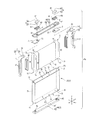
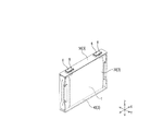
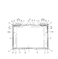
ケース3は、両端が開口した筒状のケース本体30と、該ケース本体30の一方の開口を塞ぐ第一蓋体40と、ケース本体30の反対側の開口を塞ぐ第二蓋体50とを備えている。   The case 3 includes a cylindrical case main body 30 having both ends opened, a first lid 40 that closes one opening of the case main body 30, and a second lid 50 that closes an opening on the opposite side of the case main body 30. I have.

ケース本体30は、角筒状に形成されている。そのため、ケース本体30は、それぞれが第一端部P1及び該第一端部P1の反対側の第二端部P2を有する一対の第一壁部31であって、X方向に間隔をあけて互いに対向する一対の第一壁部31と、それぞれが第一端部P3及び該第一端部P3の反対側の第二端部P4を有する一対の第二壁部32であって、一対の第一壁部31間でY方向に間隔をあけて互いに対向する一対の第二壁部32とを備えている。これにより、一対の第一壁部31の第一端部P1及び一対の第二壁部32の第一端部P3(ケース本体30の第一開口縁部33)が包囲する領域には、第一開口部34が形成され、一対の第一壁部31の第二端部P2及び一対の第二壁部32の第二端部P4(ケース本体30の第二開口縁部35)が包囲する領域には、第二開口部36が形成されている。   The case body 30 is formed in a rectangular tube shape. Therefore, the case main body 30 is a pair of first wall portions 31 each having a first end portion P1 and a second end portion P2 opposite to the first end portion P1, and is spaced apart in the X direction. A pair of first wall portions 31 facing each other and a pair of second wall portions 32 each having a first end portion P3 and a second end portion P4 opposite to the first end portion P3, A pair of second wall portions 32 facing each other with a gap in the Y direction between the first wall portions 31 is provided. Accordingly, the first end portion P1 of the pair of first wall portions 31 and the first end portion P3 of the pair of second wall portions 32 (the first opening edge portion 33 of the case main body 30) surround the first region P1. One opening 34 is formed, and the second end P2 of the pair of first walls 31 and the second end P4 of the pair of second walls 32 (the second opening edge 35 of the case body 30) surround the first opening 34. A second opening 36 is formed in the region.

本実施形態では、ケース本体30は、X方向が長手方向、Y方向が短手方向となる、断面形状が長方形状の角筒状に形成されている。そのため、第一壁部31は、Z方向に長手をなす長方形状であり、第二壁部32は、X方向に長手をなす長方形状であり、第一開口縁部33及び第二開口縁部35のそれぞれは、X方向に長手をなす長方形状である。但し、第一壁部31と第二壁部32との接続部は円弧面状に形成されている。そのため、ケース本体30の角部は、小さい曲率半径で丸められ、第一開口縁部33及び第二開口縁部35のそれぞれは、角部が丸められた長方形状となっている。   In the present embodiment, the case main body 30 is formed in a rectangular tube shape with a rectangular cross-section in which the X direction is the longitudinal direction and the Y direction is the short direction. Therefore, the 1st wall part 31 is a rectangular shape which makes a longitudinal direction in a Z direction, and the 2nd wall part 32 is a rectangular shape which makes a longitudinal direction in a X direction, and the 1st opening edge part 33 and the 2nd opening edge part Each of 35 has a rectangular shape which is long in the X direction. However, the connection part of the 1st wall part 31 and the 2nd wall part 32 is formed in circular arc surface shape. Therefore, the corner of the case body 30 is rounded with a small radius of curvature, and each of the first opening edge 33 and the second opening edge 35 has a rectangular shape with rounded corners.

なお、ケース本体30は、例えば押し出し加工により形成することができる。押し出し加工により形成することで、ケース本体30の肉厚を、深絞り加工により形成される従来型のケース本体の肉厚よりも容易に薄くすることができる。また、押し出した板材を切断するのみでケース本体30を得ることができるため、生産性を向上させることができる。   The case body 30 can be formed by, for example, extrusion processing. By forming by extruding, the thickness of the case body 30 can be easily made thinner than the thickness of the conventional case body formed by deep drawing. Moreover, since the case main body 30 can be obtained only by cutting the extruded board | plate material, productivity can be improved.

第一蓋体40は、第一開口部34を塞ぎ、第一蓋体40が下側となるようにケース3が配置される場合に、ケース3の底部となる。第二蓋体50は、第二開口部36を塞ぎ、第一蓋体40が下側となるようにケース3が配置される場合に、ケース3の頂部となる。ケース本体30、第一蓋体40及び第二蓋体50の何れも、金属製(例えばアルミニウム又はアルミニウム合金)である。ケース本体30に第一蓋体40及び第二蓋体50が溶接されることで、ケース3の内部空間が気密に形成される。   The first lid 40 closes the first opening 34 and becomes the bottom of the case 3 when the case 3 is arranged so that the first lid 40 is on the lower side. The second lid 50 closes the second opening 36 and becomes the top of the case 3 when the case 3 is arranged so that the first lid 40 is on the lower side. The case body 30, the first lid body 40, and the second lid body 50 are all made of metal (for example, aluminum or aluminum alloy). By welding the first lid body 40 and the second lid body 50 to the case body 30, the internal space of the case 3 is formed airtight.

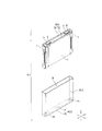
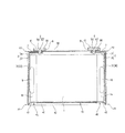
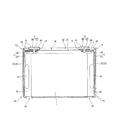
図4及び図5に示すように、第一蓋体40は、基部41と、該基部41を取り囲む外周部42とを備えている。基部41は、平坦であり、外周部42は、基部41の周縁から起立している。より詳しくは、基部41は、第一開口縁部33が矩形状乃至略矩形状であるのに対応して、矩形状乃至略矩形状ではあるが、第一開口縁部33の形状よりは小さく、そして、第一開口縁部33の端縁よりもケース本体30内にオフセットした位置に位置している。基部41の周縁から起立した外周部42の周縁は、第一開口縁部33の形状に対応して矩形状乃至略矩形状となっている。より詳しくは、外周部42の周縁は、第一開口縁部33の内周面と一致する形状、すなわち、第一開口縁部33の内周面に嵌合する形状となっている。   As shown in FIGS. 4 and 5, the first lid body 40 includes a base portion 41 and an outer peripheral portion 42 that surrounds the base portion 41. The base portion 41 is flat, and the outer peripheral portion 42 stands from the periphery of the base portion 41. More specifically, the base 41 is rectangular or substantially rectangular corresponding to the first opening edge 33 being rectangular or substantially rectangular, but smaller than the shape of the first opening edge 33. And it is located in the position offset in the case main body 30 rather than the edge of the 1st opening edge part 33. FIG. The peripheral edge of the outer peripheral portion 42 erected from the peripheral edge of the base portion 41 has a rectangular shape or a substantially rectangular shape corresponding to the shape of the first opening edge portion 33. More specifically, the peripheral edge of the outer peripheral portion 42 has a shape that matches the inner peripheral surface of the first opening edge portion 33, that is, a shape that fits to the inner peripheral surface of the first opening edge portion 33.

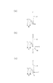
外周部42の起立高さ(Z方向の高さ)は、全周で均一になっている。そのため、外周部42の周縁は、基部41の平坦面と平行である。そして、第一蓋体40が第一開口縁部33内に嵌入された状態で、図6(a)に示すように、外周部42の周縁(第一蓋体40の周縁)は、第一開口縁部33の端縁に合わせられる。このとき、上述したとおり、外周部42の周縁は、第一開口縁部33の内周面と一致する形状であるため、第一蓋体40の周縁と第一開口縁部33の端縁とは、全周に亘って密着する。そのため、第一蓋体40が第一開口縁部33内に嵌入される前の時点でケース本体30が内側に変形していたとしても、ケース本体30は、第一蓋体40からの力fを受けて適正な形状に矯正される。   The standing height (the height in the Z direction) of the outer peripheral portion 42 is uniform over the entire circumference. Therefore, the peripheral edge of the outer peripheral portion 42 is parallel to the flat surface of the base portion 41. And in the state which the 1st cover body 40 was inserted in the 1st opening edge part 33, as shown to Fig.6 (a), the periphery (periphery of the 1st cover body 40) of the outer peripheral part 42 is 1st. Aligned with the edge of the opening edge 33. At this time, as described above, the peripheral edge of the outer peripheral portion 42 has a shape that coincides with the inner peripheral surface of the first opening edge portion 33, so that the peripheral edge of the first lid body 40 and the edge of the first opening edge portion 33 Adheres over the entire circumference. Therefore, even if the case main body 30 is deformed inward before the first lid 40 is inserted into the first opening edge portion 33, the case main body 30 is subjected to the force f from the first lid 40. To correct the shape.

外周部42は、円弧面状に形成されている。より詳しくは、外周部42は、基部41と直交乃至略直交するまで湾曲している。そのため、第一蓋体40の周縁は、第一開口縁部33の内周面に所定範囲で面接触している。図6(b)に示すように、レーザ溶接用のレーザ光は、第一蓋体40の周縁と第一開口縁部33の端縁との合わせ部に向かって照射される。レーザ光は、第一蓋体40の周縁と第一開口縁部33の端縁との合わせ部に対して正面方向(符号R1の方向)から照射してもいいし、合わせ部に対して斜め方向(符号R2の方向)から照射してもいいし、合わせ部に対して横方向(符号R3の方向)から照射してもよい。但し、第一蓋体40の周縁と第一開口縁部33の端縁との合わせ部に隙間がないために、レーザ光をR1方向から照射しても、レーザ光がケース3内に抜けてしまうことはなく、第一蓋体40の周縁と第一開口縁部33の端縁との合わせ部にレーザ光を確実に照射することができて、良好な溶接状態を得られることができるという点で、レーザ光の照射方向はR1方向であるのがより好ましい。   The outer peripheral part 42 is formed in the circular arc surface shape. More specifically, the outer peripheral portion 42 is curved until it is orthogonal to or substantially orthogonal to the base portion 41. Therefore, the peripheral edge of the first lid 40 is in surface contact with the inner peripheral surface of the first opening edge 33 within a predetermined range. As shown in FIG. 6B, the laser beam for laser welding is irradiated toward the joint portion between the peripheral edge of the first lid 40 and the edge of the first opening edge 33. The laser beam may be irradiated from the front direction (direction of reference symbol R1) to the mating portion between the peripheral edge of the first lid 40 and the edge of the first opening edge portion 33, or oblique to the mating portion. Irradiation may be performed from the direction (direction of reference R2), or irradiation may be performed from the lateral direction (direction of reference R3) with respect to the mating portion. However, since there is no gap at the joining portion between the peripheral edge of the first lid 40 and the edge of the first opening edge 33, even if the laser beam is irradiated from the R1 direction, the laser beam falls out into the case 3. The laser beam can be reliably irradiated to the mating portion between the peripheral edge of the first lid 40 and the end edge of the first opening edge 33, and a good welded state can be obtained. In this respect, the direction of laser light irradiation is more preferably the R1 direction.

そして、第一蓋体40は、基部41から起立した外周部42により断面モーメントが大きくなって高剛性となっている。そのため、溶接後(図6(c)の符号m)、第一開口縁部33側でケース3に外力Fが加わったとしても、ケース3は変形しにくくなっている。このように、第一蓋体40は、ケース本体30内で凸となり、より詳しくは、凸面状となり、ケース3の形状安定性(定型性)に大きく寄与している。   The first lid 40 has a high rigidity due to an increased cross-sectional moment due to the outer peripheral portion 42 erected from the base portion 41. For this reason, after welding (symbol m in FIG. 6C), even if an external force F is applied to the case 3 on the first opening edge 33 side, the case 3 is hardly deformed. As described above, the first lid body 40 is convex in the case main body 30, more specifically in a convex shape, and greatly contributes to the shape stability (standardity) of the case 3.

なお、第一蓋体40は、平坦な板材をプレス加工や絞り加工したものである。第一蓋体40の肉厚は、ケース本体30の肉厚と同じであってよく、あるいは、ケース本体30の肉厚よりも薄いか、逆に厚くてもよい。第一蓋体40の肉厚は、第一蓋体40が発現すべき剛性によって選択され得る。   The first lid 40 is obtained by pressing or drawing a flat plate material. The wall thickness of the first lid 40 may be the same as the wall thickness of the case body 30, or may be thinner than the wall thickness of the case body 30 or vice versa. The thickness of the first lid 40 can be selected depending on the rigidity that the first lid 40 should develop.

ここで、図1乃至図5に示すように、第一蓋体40は、ケース3の内部圧力が一定以上の値になった際に、開裂によりケース3の内部圧力を開放させるガス排出弁45を備えている。ガス排出弁45は、一例として、第一蓋体40の一部を、高まったケース3の内部圧力によって開裂できる程度に薄肉化し(、さらには、ハーフカット線を形成し)た構成である。   Here, as shown in FIGS. 1 to 5, the first lid 40 has a gas discharge valve 45 for releasing the internal pressure of the case 3 by cleaving when the internal pressure of the case 3 becomes a certain value or more. It has. As an example, the gas discharge valve 45 has a configuration in which a part of the first lid 40 is thinned to such an extent that it can be cleaved by the increased internal pressure of the case 3 (and further, a half-cut line is formed).

本実施形態では、第一蓋体40は、X方向に間隔をあけて配置された一対のガス排出弁45を備えている。一方のガス排出弁45は、第一蓋体40の基部41の一端部に形成され、他方のガス排出弁45は、基部41の他端部に形成されている。そのため、第一蓋体40が下側となるようにケース3が配置される場合に、一方のガス排出弁45は、ケース3の底部のX方向における一端部に位置し、他方のガス排出弁45は、ケース3の底部のX方向における他端部に位置する。一方のガス排出弁45は、電極体1のうち、正極リード部14(の折り返し部11)と対向し、他方のガス排出弁45は、負極リード部16(の折り返し部11)と対向している。   In the present embodiment, the first lid body 40 includes a pair of gas discharge valves 45 arranged at intervals in the X direction. One gas discharge valve 45 is formed at one end of the base 41 of the first lid 40, and the other gas discharge valve 45 is formed at the other end of the base 41. Therefore, when the case 3 is arranged so that the first lid 40 is on the lower side, one gas discharge valve 45 is located at one end in the X direction of the bottom of the case 3 and the other gas discharge valve 45 is located at the other end of the bottom of the case 3 in the X direction. One gas discharge valve 45 faces the positive electrode lead portion 14 (the folded portion 11) of the electrode body 1, and the other gas discharge valve 45 faces the negative electrode lead portion 16 (the folded portion 11). Yes.

第二蓋体50は、基本的には、第一蓋体40と同じ構成である。すなわち、第二蓋体50は、基部53と、該基部53を取り囲む外周部54とを備えている。基部53は、平坦であり、外周部54は、基部53の周縁から起立している。より詳しくは、基部53は、第二開口縁部35が矩形状乃至略矩形状であるのに対応して、矩形状乃至略矩形状ではあるが、第二開口縁部35の形状よりは小さく、そして、第二開口縁部35の端縁よりもケース本体30内にオフセットした位置に位置している。基部53の周縁から起立した外周部54の周縁は、第二開口縁部35の形状に対応して矩形状乃至略矩形状となっている。より詳しくは、外周部54の周縁は、第二開口縁部35の内周面と一致する形状、すなわち、第二開口縁部35の内周面に嵌合する形状となっている。   The second lid 50 basically has the same configuration as the first lid 40. That is, the second lid body 50 includes a base portion 53 and an outer peripheral portion 54 that surrounds the base portion 53. The base 53 is flat, and the outer peripheral part 54 stands up from the periphery of the base 53. More specifically, the base 53 is rectangular or substantially rectangular corresponding to the second opening edge 35 being rectangular or substantially rectangular, but is smaller than the shape of the second opening edge 35. And it is located in the position offset in the case main body 30 rather than the edge of the 2nd opening edge part 35. As shown in FIG. The peripheral edge of the outer peripheral portion 54 erected from the peripheral edge of the base 53 has a rectangular shape or a substantially rectangular shape corresponding to the shape of the second opening edge portion 35. More specifically, the peripheral edge of the outer peripheral portion 54 has a shape that matches the inner peripheral surface of the second opening edge portion 35, that is, a shape that fits to the inner peripheral surface of the second opening edge portion 35.

外周部54の起立高さ(Z方向の高さ)は、全周で均一になっている。そのため、外周部54の周縁は、基部53の平坦面と平行である。そして、第二蓋体50が第二開口縁部35内に嵌入された状態で、外周部54の周縁(第二蓋体50の周縁)は、第二開口縁部35の端縁に合わせられる。このとき、上述したとおり、外周部54の周縁は、第二開口縁部35の内周面と一致する形状であるため、第二蓋体50の周縁と第二開口縁部35の端縁とは、全周に亘って密着する。そのため、第二蓋体50が第二開口縁部35内に嵌入される前の時点でケース本体30が内側に変形していたとしても、ケース本体30は、第二蓋体50からの力を受けて適正な形状に矯正される。   The standing height (the height in the Z direction) of the outer peripheral portion 54 is uniform over the entire circumference. Therefore, the peripheral edge of the outer peripheral portion 54 is parallel to the flat surface of the base portion 53. In the state where the second lid 50 is fitted in the second opening edge 35, the periphery of the outer peripheral portion 54 (the periphery of the second lid 50) is aligned with the edge of the second opening edge 35. . At this time, as described above, the peripheral edge of the outer peripheral portion 54 has a shape that coincides with the inner peripheral surface of the second opening edge 35, and therefore, the peripheral edge of the second lid 50 and the edge of the second opening edge 35 Adheres over the entire circumference. Therefore, even if the case main body 30 is deformed inward before the second lid 50 is fitted into the second opening edge 35, the case main body 30 does not receive the force from the second lid 50. It is received and corrected to an appropriate shape.

外周部54は、円弧面状に形成されている。より詳しくは、外周部54は、基部53と直交乃至略直交するまで湾曲している。そのため、第二蓋体50の周縁は、第二開口縁部35の内周面に所定範囲で面接触している。レーザ溶接用のレーザ光は、第二蓋体50の周縁と第二開口縁部35の端縁との合わせ部に向かって照射される。レーザ光は、第二蓋体50の周縁と第二開口縁部35の端縁との合わせ部に対して正面方向から照射してもいいし、合わせ部に対して斜め方向から照射してもいいし、合わせ部に対して横方向から照射してもよい。但し、第二蓋体50の周縁と第二開口縁部35の端縁との合わせ部に隙間がないために、レーザ光を正面方向から照射しても、レーザ光がケース3内に抜けてしまうことはなく、第二蓋体50の周縁と第二開口縁部35の端縁との合わせ部にレーザ光を確実に照射することができて、良好な溶接状態を得られることができるという点で、レーザ光の照射方向は正面方向であるのがより好ましい。   The outer peripheral part 54 is formed in the circular arc surface shape. More specifically, the outer peripheral portion 54 is curved until it is orthogonal to or substantially orthogonal to the base portion 53. Therefore, the peripheral edge of the second lid 50 is in surface contact with the inner peripheral surface of the second opening edge 35 within a predetermined range. The laser beam for laser welding is irradiated toward the joint between the peripheral edge of the second lid 50 and the edge of the second opening edge 35. The laser beam may be irradiated from the front direction to the mating portion between the peripheral edge of the second lid 50 and the end edge of the second opening edge 35, or may be irradiated from an oblique direction to the mating portion. Alternatively, irradiation may be performed from the lateral direction with respect to the mating portion. However, since there is no gap at the joint between the peripheral edge of the second lid 50 and the edge of the second opening edge 35, even if the laser beam is irradiated from the front direction, the laser beam is released into the case 3. The laser beam can be reliably irradiated to the mating portion between the peripheral edge of the second lid 50 and the edge of the second opening edge 35, and a good welded state can be obtained. In this respect, it is more preferable that the irradiation direction of the laser light is the front direction.

そして、第二蓋体50は、基部53から起立した外周部54により断面モーメントが大きくなって高剛性となっている。そのため、溶接後、第二開口縁部35側でケース3に外力が加わったとしても、ケース3は変形しにくくなっている。このように、第二蓋体50は、ケース本体30内で凸となり、より詳しくは、凸面状となり、ケース3の形状安定性(定型性)に大きく寄与している。   The second lid 50 has a high rigidity due to a large sectional moment due to the outer peripheral portion 54 erected from the base 53. Therefore, even if an external force is applied to the case 3 on the second opening edge 35 side after welding, the case 3 is difficult to deform. As described above, the second lid body 50 is convex in the case main body 30, more specifically in a convex shape, and greatly contributes to the shape stability (standardity) of the case 3.

なお、第二蓋体50は、平坦な板材をプレス加工や絞り加工したものである。第二蓋体50の肉厚は、ケース本体30の肉厚と同じであってよく、あるいは、ケース本体30の肉厚よりも薄いか、逆に厚くてもよい。第二蓋体50の肉厚は、第二蓋体50が発現すべき剛性によって選択され得る。   The second lid 50 is obtained by pressing or drawing a flat plate material. The wall thickness of the second lid 50 may be the same as the wall thickness of the case body 30, or may be thinner than the wall thickness of the case body 30, or vice versa. The thickness of the second lid 50 can be selected depending on the rigidity that the second lid 50 should develop.

第二蓋体50は、X方向に間隔をあけて配置された一対の貫通孔51を備えている。一方の貫通孔51は、X方向における第二蓋体50の一端部に形成され、他方の貫通孔51は、X方向における第二蓋体50の他端部に形成されている。   The second lid body 50 is provided with a pair of through holes 51 arranged with a gap in the X direction. One through hole 51 is formed at one end of the second lid 50 in the X direction, and the other through hole 51 is formed at the other end of the second lid 50 in the X direction.

外部端子6は、胴部60と、該胴部60から突出するかしめ部63とを備えている。胴部60は、平坦面61を有し、該平坦面61にバスバー(図示しない)が載置され、溶接により接続される。すなわち、外部端子6は、溶接タイプの外部端子である。胴部60は、第二蓋体50の幅(Y方向の幅)よりも幅狭に形成されている。胴部60は、X方向に長い直方体状である。かしめ部63は、少なくとも先端側が塑性変形(かしめ処理)可能に構成される。かしめ部63は、胴部60の第二蓋体50との対向面の中心から突出している。   The external terminal 6 includes a body portion 60 and a caulking portion 63 protruding from the body portion 60. The body 60 has a flat surface 61, and a bus bar (not shown) is placed on the flat surface 61 and connected by welding. That is, the external terminal 6 is a welding type external terminal. The body portion 60 is formed narrower than the width of the second lid body 50 (the width in the Y direction). The trunk | drum 60 is a rectangular parallelepiped shape long in a X direction. The caulking portion 63 is configured so that at least the tip side can be plastically deformed (caulking process). The caulking portion 63 protrudes from the center of the surface of the body portion 60 facing the second lid body 50.

内部ガスケット7は、電気絶縁性及び封止性を備えた合成樹脂成型品である。内部ガスケット7は、集電体2の第二接続部24全体と対向可能なサイズに設定されている。内部ガスケット7は、第二接続部24の貫通孔25と一致する貫通孔70を備えている。   The internal gasket 7 is a synthetic resin molded product having electrical insulation and sealing properties. The internal gasket 7 is set to a size that can face the entire second connection portion 24 of the current collector 2. The internal gasket 7 includes a through hole 70 that matches the through hole 25 of the second connection portion 24.

外部ガスケット8は、内部ガスケット7と同様、電気絶縁性と封止性を備えた合成樹脂成型品である。外部ガスケット8は、外部端子6の胴部60を受け入れる凹部80を備えている。外部ガスケット8は、外部端子6の胴部60が凹部80に収容された状態で、外部端子6のかしめ部63を挿通可能な貫通孔81を備えている。   The outer gasket 8 is a synthetic resin molded product having electrical insulation and sealing properties, like the inner gasket 7. The external gasket 8 includes a recess 80 that receives the body 60 of the external terminal 6. The external gasket 8 includes a through hole 81 through which the caulking portion 63 of the external terminal 6 can be inserted in a state where the body portion 60 of the external terminal 6 is accommodated in the recess 80.

なお、第二蓋体50の外周部54の基部53からの起立高さ(Z方向の高さ)は、第一蓋体40の外周部42の基部41からの起立高さと同じであってよく、あるいは、第一蓋体40の外周部42の基部41からの起立高さよりも高いか、逆に低くてもよいが、第二蓋体50の基部53に配置される外部ガスケット8と第一蓋体40との沿面距離が長くなるよう、外部ガスケット8の外壁部は、その上端面が第二蓋体50の周縁から外方に突出する高さに形成されるのが好ましい。   The standing height (the height in the Z direction) from the base 53 of the outer peripheral portion 54 of the second lid 50 may be the same as the standing height from the base 41 of the outer peripheral portion 42 of the first lid 40. Alternatively, it may be higher than the standing height from the base portion 41 of the outer peripheral portion 42 of the first lid 40, or conversely, it may be lower, but the external gasket 8 disposed on the base 53 of the second lid 50 and the first The outer wall portion of the outer gasket 8 is preferably formed at a height such that the upper end surface of the outer gasket 8 protrudes outward from the peripheral edge of the second lid 50 so that the creepage distance with the lid 40 is increased.

外部端子6のかしめ部63は、外部ガスケット8の貫通孔81、第二蓋体50の貫通孔51、内部ガスケット7の貫通孔70及び集電体2の第二接続部24の貫通孔25に連続して挿通される。そして、かしめ部63のうち、集電体2の第二接続部24から内方に突出した先端部がかしめ処理される。これにより、外部端子6は、外部ガスケット8及び内部ガスケット7によって第二蓋体50と絶縁が図られた状態で、第二蓋体50と一体化され、且つ、集電体2と電気的に接続される。   The caulking portion 63 of the external terminal 6 is formed in the through hole 81 of the external gasket 8, the through hole 51 of the second lid 50, the through hole 70 of the internal gasket 7, and the through hole 25 of the second connection portion 24 of the current collector 2. It is inserted continuously. And the front-end | tip part which protruded inward from the 2nd connection part 24 of the electrical power collector 2 among the crimping parts 63 is crimped. As a result, the external terminal 6 is integrated with the second lid 50 while being insulated from the second lid 50 by the external gasket 8 and the internal gasket 7, and is electrically connected to the current collector 2. Connected.

以上の構成からなる本実施形態に係る電池Psによれば、ケース本体30が押し出し加工で形成され、その両端の開口縁部33,35に蓋体40,50が溶接されてケース3が作製される。そのため、ケース本体が深絞り加工により形成され、その一端の開口縁部に蓋体が溶接されて作製される従来型のケースに比べて、ケースを安価に作製することができ、電池の製造コストを削減することができる。また、深絞り加工に比べ、作製できる形状の自由度が高いため、ケース3の設計の自由度、ひいては電池Psの設計の自由度が高くなるという利点もある。   According to the battery Ps according to the present embodiment configured as described above, the case body 30 is formed by extrusion processing, and the case bodies 3 are manufactured by welding the lid bodies 40 and 50 to the opening edge portions 33 and 35 at both ends thereof. The Therefore, the case can be manufactured at a lower cost than the conventional case in which the case body is formed by deep drawing and a lid is welded to the opening edge of one end thereof, and the battery manufacturing cost can be reduced. Can be reduced. Further, since the degree of freedom of the shape that can be produced is higher than that of deep drawing, there is an advantage that the degree of freedom in designing the case 3 and thus the degree of freedom in designing the battery Ps are increased.

また、本実施形態に係る電池Psによれば、ケース本体30が押し出し加工により形成されるため、ケース本体30の肉厚を薄くすることができる。これにより、従来型の電池に比べて電池を軽量化できるとともに、ケース本体30の肉厚を薄くことで、発電に寄与しない部分(ケース3)を減容することができ、単位体積あたりの発電効率(エネルギー密度)を高めることができる。   Further, according to the battery Ps according to the present embodiment, the case main body 30 is formed by extrusion processing, so that the thickness of the case main body 30 can be reduced. As a result, the weight of the battery can be reduced compared to the conventional battery, and the thickness of the case body 30 can be reduced to reduce the volume of the portion that does not contribute to power generation (case 3). Efficiency (energy density) can be increased.

また、ケース本体30が薄肉化されることで、ケース本体30の剛性が落ち、変形しやすくなるが、第二蓋体50はもちろんのこと、特に第一蓋体40がケース本体30の保形手段としてケース本体30の形状安定性を担保するため、ケース3の大幅な剛性低下を抑制することができる。第一蓋体40によりケース本体30が型崩れしないということは、ケース本体30の第二開口部36から電極体1が挿入される際、電極体1が第二開口縁部35に不用意に当たって傷付くのが防止されるということのみならず、第二開口部36を塞いだ第二蓋体50の周縁と第二開口縁部35の端縁との間に隙間が生じてしまい、第二蓋体50が第二開口縁部35に溶接される際、レーザ光が内部に抜けてケース3内の電極体1がダメージを受ける、といった事態が防止されるということである。すなわち、第一蓋体40は、ケース本体30の形状安定性を担保することで、第二開口縁部35の端縁の平面性が担保され、これにより、第二蓋体50の周縁と第二開口縁部35の端縁との間に隙間が生じるのが防止される。   Further, since the case main body 30 is thinned, the case main body 30 is less rigid and easily deformed. In addition to the second lid 50, the first lid 40 is the shape-retaining shape of the case main body 30. Since the shape stability of the case main body 30 is ensured as a means, a significant reduction in rigidity of the case 3 can be suppressed. The fact that the case body 30 is not deformed by the first lid 40 means that when the electrode body 1 is inserted from the second opening 36 of the case body 30, the electrode body 1 inadvertently hits the second opening edge 35. Not only is it prevented from being scratched, but a gap is created between the peripheral edge of the second lid 50 closing the second opening 36 and the edge of the second opening edge 35, and the second This means that when the lid 50 is welded to the second opening edge 35, a situation in which the laser beam passes inside and the electrode body 1 in the case 3 is damaged is prevented. That is, the first lid 40 ensures the shape stability of the case main body 30, thereby ensuring the flatness of the edge of the second opening edge 35, and thereby the first lid 40 and the peripheral edge of the second lid 50. It is possible to prevent a gap from being formed between the edge of the two opening edges 35.

また、第一蓋体40の周縁がケース本体30の第一開口縁部33の内周面と一致する形状であるため、第一蓋体40が第一開口縁部33内に嵌入されると、ケース本体30の第一開口縁部33の端縁が第一蓋体40の周縁に密着する。そして、そればかりでなく、第一蓋体40の剛性がケース本体30よりも高いため、嵌入に先立ち、たとえケース本体30が変形していたとしても、第一開口縁部33が第一蓋体40の周縁に倣い、ケース本体30がしかるべき形状に矯正されることとなる。   In addition, since the periphery of the first lid 40 has a shape that matches the inner peripheral surface of the first opening edge 33 of the case body 30, the first lid 40 is fitted into the first opening edge 33. The edge of the first opening edge 33 of the case body 30 is in close contact with the peripheral edge of the first lid 40. In addition, since the rigidity of the first lid body 40 is higher than that of the case main body 30, even if the case main body 30 is deformed prior to insertion, the first opening edge 33 is formed in the first lid body. The case main body 30 is corrected to an appropriate shape following the periphery of 40.

また、本実施形態に係る電池Psによれば、第一蓋体40の周縁とケース本体30の第一開口縁部33の端縁との密着性及び第二蓋体50の周縁とケース本体30の第二開口縁部35の端縁との密着性が高いため、両者の合わせ部に対して正面(すなわち、Z方向)からレーザ光を照射しても、レーザ光がケース3内に抜けてしまうことはなく、第一蓋体40の周縁と第一開口縁部33の端縁との合わせ部及び第二蓋体50の周縁と第二開口縁部35の端縁との合わせ部にレーザ光を確実に照射することができて、良好な溶接状態を得られることができる。なお、レーザ光を斜め方向(図6(b)の符号R2を参照)から照射すれば、レーザ光の抜けをさほど気にする必要はないが、レーザ光を出射する溶接ヘッドの傾斜角度を変更・調整する機構などが必要となり、溶接設備が大がかりなものとなってしまう。また、そればかりでなく、第一蓋体40の周縁と第一開口縁部33の端縁との合わせ部及び第二蓋体50の周縁と第二開口縁部35の端縁との合わせ部を全周に亘って溶接するために溶接ヘッドがXY平面を移動しつつZ軸回りに回転する動きとなるが、その動きを制御する加工プログラムが複雑になり、加工プログラムの作成に時間と費用がかかるという問題がある。レーザ光を横方向(図6(b)の符号R3を参照)から照射すれば、レーザ光の抜けの問題は全くなくなるが、第一蓋体40の周縁と第一開口縁部33の端縁との合わせ部及び第二蓋体50の周縁と第二開口縁部35の端縁との合わせ部にレーザ光を適切に照射できなくなるおそれがある。但し、レーザ光を斜め方向に照射する方式であれば、対象物に当たったレーザ光がヘッドに反射することはないため、溶接設備に取って好ましく、また、レーザ光を横方向から照射する方式であれば、出力を上げることで、適切に溶接することができる。要は、状況に応じてレーザ光の照射方向をどうするかは適宜選択することができる。   Further, according to the battery Ps according to the present embodiment, the adhesion between the peripheral edge of the first lid body 40 and the edge of the first opening edge 33 of the case main body 30 and the peripheral edge of the second lid body 50 and the case main body 30. Since the adhesiveness with the edge of the second opening edge 35 is high, even if the laser beam is irradiated from the front (that is, in the Z direction) to the mating portion of both, the laser beam escapes into the case 3 The laser is not applied to the joining portion between the peripheral edge of the first lid 40 and the end edge of the first opening edge 33 and the joining portion between the peripheral edge of the second lid 50 and the edge of the second opening edge 35. Light can be reliably irradiated and a good welding state can be obtained. Note that if the laser beam is irradiated from an oblique direction (see symbol R2 in FIG. 6B), there is no need to worry about the laser beam dropping, but the tilt angle of the welding head that emits the laser beam is changed.・ Adjustment mechanism is required and welding equipment becomes large. Not only that, but also the mating part of the peripheral edge of the first lid 40 and the edge of the first opening edge 33 and the mating part of the peripheral edge of the second lid 50 and the edge of the second opening edge 35. The welding head moves around the XY plane and rotates around the Z axis to weld the entire circumference, but the machining program that controls the movement becomes complicated, and it takes time and money to create the machining program. There is a problem that it takes. If the laser beam is irradiated from the lateral direction (see reference numeral R <b> 3 in FIG. 6B), the problem of the laser beam omission disappears at all, but the peripheral edge of the first lid 40 and the edge of the first opening edge 33. There is a possibility that the laser beam cannot be appropriately irradiated to the mating portion and the mating portion of the peripheral edge of the second lid 50 and the end edge of the second opening edge portion 35. However, if it is a method of irradiating laser light in an oblique direction, the laser light hitting the object will not be reflected on the head, so it is preferable for welding equipment, and a method of irradiating laser light from the lateral direction If so, it is possible to appropriately weld by increasing the output. In short, it is possible to appropriately select the laser light irradiation direction depending on the situation.

また、本実施形態に係る電池Psによれば、第一蓋体40の外周部42が基部41と直交乃至略直交するまで湾曲し、第二蓋体50の外周部54が基部53と直交乃至略直交するまで湾曲している。そのため、第一蓋体40の周縁は、第一開口縁部33の内周面に所定範囲で面接触し、第二蓋体50の周縁は、第二開口縁部35の内周面に所定範囲で面接触している。これにより、第一開口縁部33と第一蓋体40との接合強度及び第二開口縁部35と第二蓋体50との接合強度をより高めることができる。   Further, according to the battery Ps according to the present embodiment, the outer peripheral portion 42 of the first lid body 40 is curved until it is orthogonal to or substantially orthogonal to the base portion 41, and the outer peripheral portion 54 of the second lid body 50 is orthogonal to the base portion 53. Curved until approximately orthogonal. Therefore, the peripheral edge of the first lid body 40 is in surface contact with the inner peripheral surface of the first opening edge portion 33 within a predetermined range, and the peripheral edge of the second lid body 50 is predetermined on the inner peripheral surface of the second opening edge portion 35. Surface contact in range. Thereby, the joint strength between the first opening edge 33 and the first lid 40 and the joint strength between the second opening edge 35 and the second lid 50 can be further increased.

また、本実施形態に係る電池Psによれば、ガス排出弁45は、ケース3のうち、外部端子6が設けられた面とは反対側の面に設けられている。すなわち、ガス排出弁45は、外部端子6が第二蓋体50に設けられているのに対して、第二蓋体50とは反対側に位置する第一蓋体40に設けられている。そのため、外部端子6とガス排出弁45とは、ケース3において、真反対の配置関係となり、ガス排出弁45が外部端子6から最も離れた箇所にある。したがって、ガス排出弁45が作動した場合に、ガス排出弁45から排出されるガスあるいはガスの排出に伴って排出される電解液が外部端子6あるいは外部端子6に接続されるバスバーあるいは外部端子6やバスバーに接続される電力線や信号線に付着するのを防止することができる。   Further, according to the battery Ps according to the present embodiment, the gas discharge valve 45 is provided on the surface of the case 3 opposite to the surface on which the external terminal 6 is provided. That is, the gas discharge valve 45 is provided on the first lid 40 located on the opposite side of the second lid 50, while the external terminal 6 is provided on the second lid 50. Therefore, the external terminal 6 and the gas discharge valve 45 are in the opposite relationship in the case 3, and the gas discharge valve 45 is at a position farthest from the external terminal 6. Therefore, when the gas discharge valve 45 is activated, the gas discharged from the gas discharge valve 45 or the electrolyte discharged with the discharge of the gas is the external terminal 6 or the bus bar connected to the external terminal 6 or the external terminal 6. It is possible to prevent adhesion to power lines and signal lines connected to the bus bar.

なお、仮にガス排出弁がケース本体30に形成される、すなわち、外部端子6の側方領域にガス排出弁が設けられるとした場合であっても、ガス排出弁は、外部端子から離れた箇所に設けられることになる。しかしながら、ガス排出弁が上側となるようにケース3が配置される場合、ガス排出弁が作動すると、ガス排出弁から排出された電解液がケース本体30の表面を伝って液垂れし、外部端子6あるいはその周辺に付着する可能性は否定できない。本実施形態に係る電池Psによれば、ガス排出弁45が外部端子6から最も離れた箇所にあり、しかも、ガス排出弁45から外部端子6に至るまで直交箇所が二箇所存在する。そのため、ガス排出弁45から排出された電解液が液垂れして外部端子6に到達する可能性は極めて低い。このように、本実施形態に係る電池Psによれば、ガス排出弁が外部端子6から離れた箇所に設けられるだけではない顕著な効果が奏される。   Even if the gas discharge valve is formed in the case body 30, that is, when the gas discharge valve is provided in the lateral region of the external terminal 6, the gas discharge valve is located away from the external terminal. Will be provided. However, when the case 3 is arranged so that the gas discharge valve is on the upper side, when the gas discharge valve is operated, the electrolyte discharged from the gas discharge valve is dripped down along the surface of the case main body 30, and the external terminal The possibility of adhering to or around 6 is undeniable. According to the battery Ps according to the present embodiment, the gas discharge valve 45 is located farthest from the external terminal 6, and there are two orthogonal positions from the gas discharge valve 45 to the external terminal 6. Therefore, the possibility that the electrolyte discharged from the gas discharge valve 45 drips and reaches the external terminal 6 is extremely low. As described above, according to the battery Ps according to the present embodiment, not only the gas discharge valve is provided at a location away from the external terminal 6, but a remarkable effect is exhibited.

しかも、ガス排出弁45は、第一蓋体40のうち、ケース本体30の第一開口縁部33の端縁よりもケース本体30内にオフセットした位置に位置する基部41に設けられている。すなわち、ガス排出弁45は、第一蓋体40の外周部42やケース本体30の第一開口縁部33に囲われた状態となっている。そのため、ガス排出弁45が作動した場合に、第一蓋体40の外周部42やケース本体30の第一開口縁部33によってガスの拡散が規制される。   In addition, the gas discharge valve 45 is provided in the base 41 located at a position offset in the case body 30 from the end edge of the first opening edge 33 of the case body 30 in the first lid 40. That is, the gas discharge valve 45 is in a state surrounded by the outer peripheral portion 42 of the first lid body 40 and the first opening edge portion 33 of the case body 30. Therefore, when the gas discharge valve 45 is actuated, gas diffusion is regulated by the outer peripheral portion 42 of the first lid 40 and the first opening edge portion 33 of the case body 30.

また、ガス排出弁45は、第一蓋体40のうち、ケース本体30の第一開口縁部33の端縁よりもケース本体30内に位置することで、ケース3の外形線よりも内側に位置している。そのため、電池Psが配置されても、ガス排出弁45が配置面と接触することはない。これにより、ガス排出弁45が不用意に外力を受けて脆弱化し、所期の力よりも小さい力で作動してしまうといった事態が生じるのを防止することができる。   Further, the gas discharge valve 45 is positioned inside the case body 30 in the first lid body 40 from the edge of the first opening edge 33 of the case body 30, so that the gas discharge valve 45 is located inside the outer line of the case 3. positioned. Therefore, even if the battery Ps is arranged, the gas discharge valve 45 does not come into contact with the arrangement surface. As a result, it is possible to prevent the gas discharge valve 45 from being inadvertently weakened by receiving an external force and operating with a force smaller than the intended force.

また、ガス排出弁45は、正極リード部14及び負極リード部16の近傍位置に設けられている。ガスは、電極体1内で発生し、開放端となっている正極リード部14及び負極リード部16から抜けるようになっている。そのため、ガス排出弁45が正極リード部14及び負極リード部16の近傍位置に設けられていると、ケース3内での排出経路が短くなり(最短となり)、ガスの排出が円滑化される。   The gas discharge valve 45 is provided in the vicinity of the positive electrode lead portion 14 and the negative electrode lead portion 16. The gas is generated in the electrode body 1 and escapes from the positive electrode lead portion 14 and the negative electrode lead portion 16 which are open ends. Therefore, if the gas discharge valve 45 is provided in the vicinity of the positive electrode lead portion 14 and the negative electrode lead portion 16, the discharge path in the case 3 is shortened (shortest), and the gas discharge is facilitated.

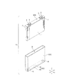
次に、本実施形態に係る電池Psを一方向に整列させて一体化させた電池モジュールについて、図7を参酌しつつ説明する。   Next, a battery module in which the batteries Ps according to the present embodiment are aligned and integrated in one direction will be described with reference to FIG.

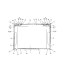
本実施形態に係る電池モジュールMは、Y方向に整列される複数の電池Psと、隣り合う電池Ps間及びY方向における複数の電池Psの両側にそれぞれ配置される複数のスペーサ100と、複数の電池Ps及び複数のスペーサ100を保持してパッケージ化する保持体としてのフレーム110とを備えている。   The battery module M according to the present embodiment includes a plurality of batteries Ps aligned in the Y direction, a plurality of spacers 100 disposed between adjacent batteries Ps and on both sides of the plurality of batteries Ps in the Y direction, and a plurality of batteries Ps. A frame 110 as a holding body that holds and packages the battery Ps and the plurality of spacers 100 is provided.

スペーサ100は、合成樹脂製であり、絶縁性を有している。本実施形態に係る電池モジュールでは、電池Psの冷却方式として、隣り合う電池Ps間や隣り合う電池Ps及び終端部材111(後述する)間を空気が流通することで電池Psが冷却される、いわゆる空冷式が採用されている。そのため、スペーサ100は、隣り合う電池Ps間や隣り合う電池Ps及び終端部材111間に隙間が形成されるような形態を有している。本実施形態では、板状のスペーサ本体の表裏面から複数の凸条が互いに間隔を有して突出するスペーサ100が採用されているが、これに限定されるものではない。例えば、板状のスペーサ本体の片面から複数の凸条が互いに間隔を有して突出するスペーサや、スペーサ本体の断面形状が矩形波形状となっているスペーサなど、種々の構造のスペーサの中から適宜選択され得る。   The spacer 100 is made of synthetic resin and has an insulating property. In the battery module according to the present embodiment, as a cooling method of the battery Ps, the battery Ps is cooled by the air flowing between the adjacent batteries Ps or between the adjacent batteries Ps and the termination member 111 (described later). Air-cooled type is adopted. Therefore, the spacer 100 has a form in which a gap is formed between the adjacent batteries Ps or between the adjacent batteries Ps and the termination member 111. In the present embodiment, the spacer 100 is employed in which a plurality of protrusions protrude from the front and back surfaces of the plate-like spacer main body at intervals, but the present invention is not limited to this. For example, among spacers of various structures, such as a spacer in which a plurality of protrusions protrude from one side of a plate-like spacer body with a space between each other, or a spacer whose cross-sectional shape is a rectangular wave shape It can be selected appropriately.

隣り合う電池Ps同士や隣り合う電池Ps及び終端部材111同士は、固定部材105によって連結されている。固定部材105は、電池PsのZ方向における一端側と他端側とに適用されている。固定部材105は、X方向に沿って長尺に形成されている。固定部材105は、電池Psのケース3の一対の第一壁部31間よりも僅かに短い長さに形成されている。より詳しくは、固定部材105は、ケース本体30の丸められた角部を除く第二壁部32のX方向における長さと同じ乃至略同じ長さに形成されている。なお、ケース本体30の角部は、上述したとおり、小さい曲率半径で丸められており、円弧部が無視できる程度の大きさなので、固定部材105は、実質的には、第二壁部32のX方向における長さと同じであるといえる。   Adjacent batteries Ps or adjacent batteries Ps and termination members 111 are connected by a fixing member 105. The fixing member 105 is applied to one end side and the other end side in the Z direction of the battery Ps. The fixing member 105 is formed long along the X direction. The fixing member 105 is formed to have a length slightly shorter than between the pair of first wall portions 31 of the case 3 of the battery Ps. More specifically, the fixing member 105 is formed to have the same or substantially the same length as the length in the X direction of the second wall portion 32 excluding the rounded corner portion of the case body 30. As described above, the corner portion of the case body 30 is rounded with a small radius of curvature, and the arc portion is negligible. Therefore, the fixing member 105 is substantially formed of the second wall portion 32. It can be said that it is the same as the length in the X direction.

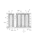
固定部材105は、Y方向に間隔をあけて配置された一対の溝部106と、該一対の溝部106間に位置する凸部107とを備えている。溝部106は、固定部材105の長手方向に沿って、すなわち、X方向に沿って形成されている。溝部106は、固定部材105の長手方向における一端から他端に亘って形成されている。凸部107も溝部106と同様に形成されている。   The fixing member 105 includes a pair of groove portions 106 arranged at intervals in the Y direction, and a convex portion 107 positioned between the pair of groove portions 106. The groove portion 106 is formed along the longitudinal direction of the fixing member 105, that is, along the X direction. The groove 106 is formed from one end to the other end in the longitudinal direction of the fixing member 105. The convex portion 107 is also formed in the same manner as the groove portion 106.

溝部106は、電池Psの第一蓋体40の周縁と第一開口縁部33の端縁との合わせ部(ケース3の凸部)、電池Psの第二蓋体50の周縁と第二開口縁部35の端縁との合わせ部(ケース3の凸部)、あるいは、終端部材111のZ方向における端部にX方向に沿って形成された凸部112が嵌り込む溝である。溝部106は、これらとの係合部として機能している。好ましくは、溝部106における封止性が向上するよう、溝部106内にパッキン等の封止部材(シール部材)が配置される。   The groove portion 106 is a mating portion (convex portion of the case 3) between the peripheral edge of the first lid 40 of the battery Ps and the edge of the first opening edge 33, and the peripheral edge and the second opening of the second lid 50 of the battery Ps. This is a groove into which a convex portion 112 formed along the X direction fits into the mating portion (the convex portion of the case 3) with the end edge of the edge portion 35 or the end portion in the Z direction of the termination member 111. The groove portion 106 functions as an engaging portion with these. Preferably, a sealing member (seal member) such as packing is disposed in the groove 106 so that the sealing performance in the groove 106 is improved.

固定部材105の凸部107は、スペーサ100のY方向における幅と同じか、それよりも僅かに小さい幅を有しており、隣り合う電池Ps間や隣り合う電池Ps及び終端部材111間に挿入される挿入部である。   The convex portion 107 of the fixing member 105 has a width that is the same as or slightly smaller than the width of the spacer 100 in the Y direction, and is inserted between adjacent batteries Ps or between adjacent batteries Ps and a termination member 111. It is an insertion part.

したがって、隣り合う電池Psは、一方の電池Psの第一蓋体40の周縁と第一開口縁部33の端縁との合わせ部が第一蓋体40側に配置された固定部材105の一方の溝部106に嵌り、他方の電池Psの第一蓋体40の周縁と第一開口縁部33の端縁との合わせ部が他方の溝部106に嵌り、さらに、凸部107が隣り合うケース3の第一蓋体40側の端部間に挿入されることで、Y方向及びY方向と直交する方向で位置ずれが生じない状態で、連結されている。また、隣り合う電池Psは、一方の電池Psの第二蓋体50の周縁と第二開口縁部35の端縁との合わせ部が第二蓋体50側に配置された固定部材105の一方の溝部106に嵌り、他方の電池Psの第二蓋体50の周縁と第二開口縁部35の端縁との合わせ部が他方の溝部106に嵌り、さらに、凸部107が隣り合うケース3の第二蓋体50側の端部間に挿入されることで、Y方向及びY方向と直交する方向で位置ずれが生じない状態で、連結されている。   Therefore, the adjacent battery Ps includes one of the fixing members 105 in which the joint portion between the peripheral edge of the first lid 40 and the edge of the first opening edge 33 of the one battery Ps is disposed on the first lid 40 side. Case 3 in which the mating portion of the peripheral edge of the first lid 40 of the other battery Ps and the edge of the first opening edge portion 33 fits in the other groove portion 106 and the convex portion 107 is adjacent to the other battery Ps. By being inserted between the end portions on the first lid body 40 side, they are connected in a state in which no positional deviation occurs in the Y direction and the direction orthogonal to the Y direction. In addition, the adjacent battery Ps includes one of the fixing members 105 in which a joint portion between the peripheral edge of the second lid 50 and the edge of the second opening edge 35 of the one battery Ps is disposed on the second lid 50 side. Case 3 in which the mating part of the peripheral edge of the second lid 50 of the other battery Ps and the end edge of the second opening edge 35 fits into the other groove part 106 and the convex part 107 is adjacent to the other battery Ps. By being inserted between the end portions on the second lid body 50 side, they are connected in a state in which no positional deviation occurs in the Y direction and the direction orthogonal to the Y direction.

隣り合う電池Ps及び終端部材111は、電池Psの第一蓋体40の周縁と第一開口縁部33の端縁との合わせ部が第一蓋体40側に配置された固定部材105の一方の溝部106に嵌り、終端部材111のZ方向における一端部側の凸部112が他方の溝部106に嵌り、さらに、凸部107がケース3の第一蓋体40側の端部及び終端部材111のZ方向における一端部間に挿入されることで、Y方向及びY方向と直交する方向で位置ずれが生じない状態で、連結されている。また、隣り合う電池Ps及び終端部材111は、電池Psの第二蓋体50の周縁と第二開口縁部35の端縁との合わせ部が第二蓋体50側に配置された固定部材105の一方の溝部106に嵌り、終端部材111のZ方向における他端部側の凸部112が他方の溝部106に嵌り、さらに、凸部107がケース3の第二蓋体50側の端部及び終端部材111のZ方向における他端部間に挿入されることで、Y方向及びY方向と直交する方向で位置ずれが生じない状態で、連結されている。   The adjacent battery Ps and the termination member 111 are one of the fixing members 105 in which the joint portion between the peripheral edge of the first lid 40 and the edge of the first opening edge 33 of the battery Ps is disposed on the first lid 40 side. The projection 112 on one end side in the Z direction of the end member 111 is fitted on the other groove 106, and the projection 107 is the end on the first lid 40 side of the case 3 and the end member 111. By being inserted between the one end portions in the Z direction, the Y direction and the direction orthogonal to the Y direction are connected in a state where no positional deviation occurs. Moreover, the adjacent battery Ps and the termination | terminus member 111 are the fixing member 105 by which the joint part of the periphery of the 2nd cover body 50 of the battery Ps and the edge of the 2nd opening edge part 35 was arrange | positioned at the 2nd cover body 50 side. Of the end member 111 in the Z direction, the convex portion 112 on the other end side in the Z direction fits into the other groove portion 106, and the convex portion 107 further includes the end portion on the second lid 50 side of the case 3 and By being inserted between the other ends of the end member 111 in the Z direction, the end member 111 is connected in a state in which no positional deviation occurs in the Y direction and the direction orthogonal to the Y direction.

フレーム110は、Y方向における複数の電池Psの両側に配置され且つY方向において複数の電池Ps及び複数のスペーサ100を挟み込む一対の終端部材111(いわゆるエンドプレート)と、該一対の終端部材111同士を連結し、複数の電池Ps及び複数のスペーサ100を一体に緊締する連結部材113とを備えている。すなわち、本実施形態に係る電池モジュールMは、複数の電池Psが一方向に積層された、いわゆるスタック型の電池モジュールMである。   The frame 110 is disposed on both sides of the plurality of batteries Ps in the Y direction, and a pair of termination members 111 (so-called end plates) sandwiching the plurality of batteries Ps and the plurality of spacers 100 in the Y direction, and the pair of termination members 111 And a connecting member 113 for integrally fastening the plurality of batteries Ps and the plurality of spacers 100 together. That is, the battery module M according to the present embodiment is a so-called stack type battery module M in which a plurality of batteries Ps are stacked in one direction.

終端部材111は、例えば鋳造によって形成された、例えばアルミなどの金属製である。終端部材111は、スペーサ100と同様、電池Psのケース3がY方向から見て矩形状であるのに対応し、矩形状に形成されている。終端部材111は、矩形状の枠部と、該枠部内に形成された格子形状のリブとで構成され、X方向にある程度の厚みを有しながらも、軽量であり、剛性を有している。しかしながら、この終端部材以外にも、例えば、プレス成形された板状の終端部材など、種々の構造の終端部材の中から適宜選択され得る。   The termination member 111 is made of metal such as aluminum formed by casting, for example. The termination member 111 is formed in a rectangular shape corresponding to the case 3 of the battery Ps having a rectangular shape as viewed from the Y direction, like the spacer 100. The termination member 111 is composed of a rectangular frame portion and lattice-shaped ribs formed in the frame portion, and has a certain thickness in the X direction, but is lightweight and rigid. . However, in addition to this termination member, it can be appropriately selected from termination members having various structures such as a press-molded plate-like termination member.

連結部材113は、例えばボルトなどの締結具によって終端部材111に固定されている。連結部材113は、一対の終端部材111の角部同士を連結している。そのため、連結部材113は、終端部材111の四つの角部に対応して四本配置されている。連結部材113は、図示はしないが、それぞれの固定部材105に対し、直接又は間接的にZ方向から当接している。固定部材105は、連結部材113によって電池Ps及び終端部材111からの離脱が制止されている。   The connecting member 113 is fixed to the end member 111 by a fastener such as a bolt. The connecting member 113 connects the corner portions of the pair of terminal members 111. Therefore, four connection members 113 are arranged corresponding to the four corners of the termination member 111. Although not shown, the connecting member 113 is in direct or indirect contact with each fixing member 105 from the Z direction. The fixing member 105 is prevented from being detached from the battery Ps and the terminal member 111 by the connecting member 113.

フレーム110は、複数の電池Psの第一蓋体40側を、ある程度の間隔をあけて全面的に覆う遮蔽体114をさらに備えている。遮蔽体114は、板状に形成され、Y方向における端部が終端部材111のZ方向における一端部に固定されるとともに、X方向における側端部が第一蓋体40側に配置された一対の連結部材113に直接又は間接に支持されている。   The frame 110 further includes a shield 114 that covers the entire surface of the plurality of batteries Ps on the first lid 40 side with a certain distance therebetween. The shield 114 is formed in a plate shape, an end in the Y direction is fixed to one end in the Z direction of the termination member 111, and a pair of side ends in the X direction are disposed on the first lid 40 side. The connecting member 113 is directly or indirectly supported.

以上の構成からなる本実施形態に係る電池モジュールMによれば、隣り合う電池Psの一方の電池Psの第一蓋体40の周縁と第一開口縁部33の端縁との合わせ部と第一蓋体40側に配置された固定部材105の一方の溝部106とが係合する。これにより、一方の電池Psと第一蓋体40側に配置された固定部材105とが固定(位置決め)される。また、隣り合う電池Psの他方の電池Psの第一蓋体40の周縁と第一開口縁部33の端縁との合わせ部と第一蓋体40側に配置された固定部材105の他方の溝部106とが係合する。これにより、他方の電池Psと第一蓋体40側に配置された固定部材105とが固定(位置決め)される。また、隣り合う電池Psの一方の電池Psの第二蓋体50の周縁と第二開口縁部35の端縁との合わせ部と第二蓋体50側に配置された固定部材105の一方の溝部106とが係合する。これにより、一方の電池Psと第二蓋体50側に配置された固定部材105とが固定(位置決め)される。また、隣り合う電池Psの他方の電池Psの第二蓋体50の周縁と第二開口縁部35の端縁との合わせ部と第二蓋体50側に配置された固定部材105の他方の溝部106とが係合する。これにより、他方の電池Psと第二蓋体50側に配置された固定部材105とが固定(位置決め)される。このように、隣り合う電池Psは、固定部材105を介して固定(位置決め)される。これにより、隣り合う電池Ps間の位置ずれを無くし、複数の電池Psを正しく整列させることができる。   According to the battery module M according to the present embodiment having the above-described configuration, the mating portion between the peripheral edge of the first lid body 40 and the edge of the first opening edge portion 33 of one battery Ps of the adjacent batteries Ps and the first. One groove portion 106 of the fixing member 105 arranged on the one lid 40 side is engaged. Thereby, one battery Ps and the fixing member 105 arrange | positioned at the 1st cover body 40 side are fixed (positioning). Further, the other of the fixing members 105 arranged on the first lid 40 side and the mating portion of the peripheral edge of the first lid 40 and the edge of the first opening edge 33 of the other battery Ps of the adjacent batteries Ps. The groove 106 is engaged. Thereby, the other battery Ps and the fixing member 105 disposed on the first lid 40 side are fixed (positioned). In addition, one of the fixing members 105 disposed on the side of the second lid 50 and the mating portion of the peripheral edge of the second lid 50 and the edge of the second opening edge 35 of one battery Ps of the adjacent batteries Ps. The groove 106 is engaged. Thereby, one battery Ps and the fixing member 105 arranged on the second lid 50 side are fixed (positioned). Further, the other part of the fixing member 105 disposed on the second lid 50 side and the mating portion of the peripheral edge of the second lid 50 and the edge of the second opening edge 35 of the other battery Ps of the adjacent batteries Ps. The groove 106 is engaged. As a result, the other battery Ps and the fixing member 105 arranged on the second lid 50 side are fixed (positioned). In this way, the adjacent batteries Ps are fixed (positioned) via the fixing member 105. Thereby, the position shift between the adjacent batteries Ps can be eliminated, and the plurality of batteries Ps can be correctly aligned.

また、隣り合う電池Ps及び終端部材111のうち、電池Psの第一蓋体40の周縁と第一開口縁部33の端縁との合わせ部と第一蓋体40側に配置された固定部材105の一方の溝部106とが係合する。これにより、電池Psと第一蓋体40側に配置された固定部材105とが固定(位置決め)される。また、隣り合う電池Ps及び終端部材111のうち、終端部材111の一端部側の凸部112と第一蓋体40側に配置された固定部材105の他方の溝部106とが係合する。これにより、終端部材111と第一蓋体40側に配置された固定部材105とが固定(位置決め)される。また、隣り合う電池Ps及び終端部材111のうち、電池Psの第二蓋体50の周縁と第二開口縁部35の端縁との合わせ部と第二蓋体50側に配置された固定部材105の一方の溝部106とが係合する。これにより、電池Psと第二蓋体50側に配置された固定部材105とが固定(位置決め)される。また、隣り合う電池Ps及び終端部材111のうち、終端部材111の他端部側の凸部112と第二蓋体50側に配置された固定部材105の他方の溝部106とが係合する。これにより、終端部材111と第二蓋体50側に配置された固定部材105とが固定(位置決め)される。このように、隣り合う電池Ps及び終端部材111は、固定部材105を介して固定(位置決め)される。これにより、隣り合う電池Ps及び終端部材111間の位置ずれを無くし、複数の電池Ps及び一対の終端部材111を正しく整列させることができる。   In addition, among the adjacent batteries Ps and the termination member 111, the fixing member disposed on the first lid 40 side and the mating portion of the peripheral edge of the first lid 40 and the edge of the first opening edge 33 of the battery Ps. One groove portion 106 of 105 is engaged. As a result, the battery Ps and the fixing member 105 arranged on the first lid 40 side are fixed (positioned). Further, among the adjacent batteries Ps and the termination member 111, the convex portion 112 on one end side of the termination member 111 and the other groove portion 106 of the fixing member 105 disposed on the first lid body 40 side are engaged. Thereby, the termination | terminus member 111 and the fixing member 105 arrange | positioned at the 1st cover body 40 side are fixed (positioning). In addition, among the adjacent batteries Ps and the termination member 111, the fixing member disposed on the second lid body 50 side and the mating portion between the peripheral edge of the second lid body 50 and the edge of the second opening edge 35 of the battery Ps. One groove portion 106 of 105 is engaged. Thereby, the battery Ps and the fixing member 105 disposed on the second lid body 50 side are fixed (positioned). In addition, among the adjacent batteries Ps and the termination member 111, the convex portion 112 on the other end side of the termination member 111 and the other groove portion 106 of the fixing member 105 arranged on the second lid 50 side are engaged. Thereby, the termination | terminus member 111 and the fixing member 105 arrange | positioned at the 2nd cover body 50 side are fixed (positioning). As described above, the adjacent battery Ps and the termination member 111 are fixed (positioned) via the fixing member 105. Thereby, the position shift between the adjacent battery Ps and the termination | terminus member 111 can be eliminated, and the some battery Ps and a pair of termination | terminus member 111 can be aligned correctly.

また、本実施形態に係る電池モジュールMによれば、電池Psのケース3の特殊な端部構造と該端部構造に適合する形状を有する固定部材105との組み合わせにより、電池Ps同士や電池Psと終端部材111とを確実に固定することができる。   Further, according to the battery module M according to the present embodiment, the batteries Ps and the batteries Ps are combined by combining the special end structure of the case 3 of the battery Ps and the fixing member 105 having a shape suitable for the end structure. And the termination member 111 can be securely fixed.

また、本実施形態に係る電池モジュールMによれば、隣り合う電池Ps間の隙間や隣り合う電池Ps及び終端部材111間の隙間、すなわち、冷却流路は、その両側方に配置される固定部材105によって封止されている。そのため、冷媒をX方向に沿って漏れなく流すことができ、冷却効率を高めることができる。   Further, according to the battery module M according to the present embodiment, the gap between the adjacent batteries Ps and the gap between the adjacent batteries Ps and the termination member 111, that is, the cooling flow path is a fixing member arranged on both sides thereof. It is sealed with 105. Therefore, the refrigerant can flow without leakage along the X direction, and the cooling efficiency can be improved.

また、第二蓋体50側に配置された固定部材105もそうであるが、特に第一蓋体40側に配置された固定部材105は、外部端子6とガス排出弁45とを仕切る遮蔽部材として機能している。これにより、ガス排出弁45が作動した場合に、そこから排出されるガスや電解液が外部端子6あるいはその周辺に付着するのをより効果的に防止することができる。   The fixing member 105 arranged on the second lid 50 side is also the same, but in particular, the fixing member 105 arranged on the first lid 40 side is a shielding member that partitions the external terminal 6 and the gas discharge valve 45. Is functioning. Thereby, when the gas discharge valve 45 operates, it can prevent more effectively that the gas and electrolyte solution which are discharged | emitted from there adhere to the external terminal 6 or its periphery.

そして、本実施形態に係る電池モジュールMによれば、複数の電池Psの第一蓋体40側と遮蔽体114との間に一つの空間部が形成され、これがガス排出弁45作動時のガス排出路となっているが、このガス排出路と冷却流路とは、第一蓋体40側に配置された固定部材105によって仕切られている。そのため、ガス排出弁45作動時にガス排出弁45から排出されたガスが冷媒と混合し、冷媒によってガスが拡散してしまうのを効果的に抑制することができる。   And according to battery module M concerning this embodiment, one space part is formed between the 1st lid 40 side of a plurality of batteries Ps, and shield 114, and this is the gas at the time of gas exhaust valve 45 operation. Although it is a discharge path, the gas discharge path and the cooling flow path are partitioned by a fixing member 105 disposed on the first lid 40 side. Therefore, it is possible to effectively suppress the gas discharged from the gas discharge valve 45 when the gas discharge valve 45 is operated from being mixed with the refrigerant and the gas being diffused by the refrigerant.

なお、本発明は、上記実施形態に限定されるものではなく、本発明の要旨を逸脱しない範囲で、適宜変更を加え得ることは勿論のことである。   In addition, this invention is not limited to the said embodiment, Of course, it can change suitably in the range which does not deviate from the summary of this invention.

例えば、上記実施形態において、第一蓋体40と第二蓋体50とは同じ構造、すなわち、ケース本体30内で凸となる蓋体が用いられている。これにより、上述したそれぞれの効果を第二蓋体50側でも享受することができる。特に、第二蓋体50は、電極体1がケース本体3内に挿入された状態で、ケース本体30の第二開口縁部35に溶接されるため、レーザ光のケース3内への抜けによる電極体1の損傷を防止できる点、第二蓋体50に固有の効果もある。しかしながら、これに限定されるものではない。例えば、図8〜図13に示すように、第二蓋体50は、従来型の蓋体と同様、平坦な板材であってもよい。なお、第二蓋体50の周縁は、例えばプレス加工やコイニング加工によって薄肉化されている。この薄肉部がケース本体30の第二開口縁部35の端縁に当接するようにして、第二蓋体50が第二開口部36を塞ぐ。   For example, in the said embodiment, the 1st cover body 40 and the 2nd cover body 50 have the same structure, ie, the cover body which becomes convex in the case main body 30 is used. Thereby, each effect mentioned above can be enjoyed also in the 2nd cover body 50 side. In particular, the second lid 50 is welded to the second opening edge 35 of the case main body 30 in a state where the electrode body 1 is inserted into the case main body 3, so that the laser light is pulled out into the case 3. There is an effect peculiar to the second lid 50 in that the electrode body 1 can be prevented from being damaged. However, the present invention is not limited to this. For example, as shown in FIGS. 8 to 13, the second lid 50 may be a flat plate material as in the conventional lid. The peripheral edge of the second lid 50 is thinned by, for example, pressing or coining. The second lid 50 closes the second opening 36 such that the thin wall portion comes into contact with the edge of the second opening edge 35 of the case body 30.

この場合、固定部材105とは反対側の、隣り合う電池Psの端部同士や隣り合う電池Ps及び終端部材111の端部同士には、別の固定部材108が適用されるようにしてもよい。固定部材108は、X方向に沿って長尺に形成されている。より詳しくは、固定部材108は、固定部材105と同じ長さか、第二蓋体50のX方向における長さと同じ程度の長さに形成されている。固定部材108は、連結部材113がそれぞれの固定部材108に対し、直接又は間接的にZ方向から当接することで、隣り合う電池Psの端部同士に跨って当接した状態あるいは隣り合う電池Ps及び終端部材111の端部同士に跨って当接した状態に保持されている。   In this case, another fixing member 108 may be applied to the ends of the adjacent batteries Ps on the side opposite to the fixing member 105, or to the ends of the adjacent batteries Ps and the termination member 111. . The fixing member 108 is formed in a long shape along the X direction. More specifically, the fixing member 108 is formed to have the same length as the fixing member 105 or the same length as the length of the second lid body 50 in the X direction. The fixing member 108 is in a state in which the connecting member 113 is in contact with each fixing member 108 directly or indirectly from the Z direction so as to stride over the ends of the adjacent batteries Ps or adjacent batteries Ps. And it hold | maintains in the state contact | abutted ranging over the edge parts of the termination | terminus member 111. FIG.

なお、固定部材108は、第二蓋体50と単に接しているのみである。そのため、外部端子6とガス排出弁45とを仕切る遮蔽部材として機能させるにあたり、第二蓋体50と固定部材108との間にパッキンや可撓性のリブ等の封止部材(シール部材)が配置されるのが好ましい。可撓性のリブは、固定部材108に一体化して形成されるのが好ましい。   Note that the fixing member 108 is merely in contact with the second lid 50. Therefore, when functioning as a shielding member that partitions the external terminal 6 and the gas discharge valve 45, a sealing member (seal member) such as packing or a flexible rib is provided between the second lid 50 and the fixing member 108. Preferably it is arranged. The flexible rib is preferably formed integrally with the fixing member 108.

また、外周部が起立する蓋体構造がケース本体30の片側の開口縁部にのみ採用されるとしても、上記実施形態のように、ケース3の底部側となる第一開口縁部33ではなく、外部端子構造が設けられる側となる第二開口縁部35に採用してもよい。   Moreover, even if the lid structure in which the outer peripheral portion stands is employed only in the opening edge portion on one side of the case body 30, it is not the first opening edge portion 33 that becomes the bottom portion side of the case 3 as in the above embodiment. The second opening edge 35 on the side where the external terminal structure is provided may be employed.

また、上記実施形態において、第一蓋体40の基部41は、平坦である。しかしながら、図14に示すように、基部41は、電極体1が偏平状にされることで電極体1のZ方向における端部に形成される折り返し部(円弧部)11に沿った形状の凹部43を備えていてもよい。より好ましくは、凹部43は、ケース本体30の第一開口縁部33の端縁から突出しない凹み量に設定され得る。この場合でも、隣り合う電池Psは、一方の電池Psの第一蓋体40の周縁と第一開口縁部33の端縁との合わせ部が第一蓋体40側に配置された固定部材105の一方の溝部106に嵌り、他方の電池Psの第一蓋体40の周縁と第一開口縁部33の端縁との合わせ部が他方の溝部106に嵌り、さらに、凸部107が隣り合うケース3の第一蓋体40側の端部間に挿入されることで、連結される。そして、隣り合う電池Ps及び終端部材111は、電池Psの第一蓋体40の周縁と第一開口縁部33の端縁との合わせ部が第一蓋体40側に配置された固定部材105の一方の溝部106に嵌り、終端部材111のZ方向における一端部側の凸部112が他方の溝部106に嵌り、さらに、凸部107がケース3の第一蓋体40側の端部及び終端部材111のZ方向における一端部間に挿入されることで、連結される。もちろん、固定部材105が凹部43と干渉して隣り合う電池Psあるいは隣り合う電池Ps及び終端部材111に装着できないということがないように、固定部材105のY方向における両端部の形状は、凹部43と干渉しない形状に設計されている。これらのことは、第二蓋体50が第一蓋体40と同じ構造となる場合の第二蓋体50についても同様である。   Moreover, in the said embodiment, the base 41 of the 1st cover body 40 is flat. However, as shown in FIG. 14, the base portion 41 is a recess having a shape along the folded portion (arc portion) 11 formed at the end portion in the Z direction of the electrode body 1 by making the electrode body 1 flat. 43 may be provided. More preferably, the concave portion 43 can be set to a concave amount that does not protrude from the end edge of the first opening edge portion 33 of the case body 30. Even in this case, the adjacent battery Ps includes a fixing member 105 in which a joint portion between the peripheral edge of the first lid 40 and the edge of the first opening edge 33 of one battery Ps is disposed on the first lid 40 side. Of the other battery Ps, the mating portion of the peripheral edge of the first lid 40 and the edge of the first opening edge portion 33 fits into the other groove portion 106, and the convex portion 107 is adjacent. The case 3 is connected by being inserted between the end portions on the first lid 40 side. And the adjacent battery Ps and the termination | terminus member 111 are the fixing members 105 by which the joint part of the periphery of the 1st cover body 40 and the edge of the 1st opening edge part 33 of the battery Ps was arrange | positioned at the 1st cover body 40 side. One end of the end member 111 in the Z direction, and the convex portion 112 on the one end side in the Z direction fits into the other groove portion 106. The members 111 are connected by being inserted between one end portions in the Z direction. Of course, the shape of the both ends in the Y direction of the fixing member 105 is the concave portion 43 so that the fixing member 105 does not interfere with the concave portion 43 and cannot be attached to the adjacent battery Ps or the adjacent battery Ps and the termination member 111. Designed to avoid interference with The same applies to the second lid 50 when the second lid 50 has the same structure as the first lid 40.

また、凹部43が形成されることにより、上記実施形態に係る電池Psよりもケース3の内容積が増加するため、上記実施形態に係る電池Psとケース3の高さ寸法が同じでも、電極体1の高さ寸法を大きくすることができ、その分、単位体積あたりの発電効率(エネルギー密度)を高めることができる。あるいは、上記実施形態に係る電池Psと電極体1の高さ寸法が同じであれば、ケース3の高さ寸法を小さくすることができ、同じ発電効率でも電池Psを小型化することができる。   In addition, since the inner volume of the case 3 is increased as compared with the battery Ps according to the above-described embodiment by forming the recess 43, the electrode body even if the battery Ps according to the above-described embodiment and the case 3 have the same height dimension. The height dimension of 1 can be increased, and the power generation efficiency (energy density) per unit volume can be increased accordingly. Or if the height dimension of the battery Ps which concerns on the said embodiment, and the electrode body 1 is the same, the height dimension of the case 3 can be made small and the battery Ps can be reduced in size with the same power generation efficiency.

さらには、凹部43が形成されることで、ケース3と電極体1との間の隙間が無くなる又は隙間が小さくなるため、ケース3内に貯留される電解液の量が少ない場合であっても、電解液と電極板13,15との接触を保つことができる。すなわち、電解液をケース3内に貯留させておき、毛細管現象で吸い上げられて電極体1の正極板13及び負極板15間に供給されるようにすることで、長期使用に伴う正極板13及び負極板15間の電解液の液枯れを防止することができるが、凹部43が形成されることで、ケース3内に貯留させる電解液の量を減らすことができる。   Further, since the recess 43 is formed, there is no gap between the case 3 and the electrode body 1 or the gap becomes small. Therefore, even when the amount of the electrolyte stored in the case 3 is small The contact between the electrolytic solution and the electrode plates 13 and 15 can be maintained. That is, the electrolytic solution is stored in the case 3 and is sucked up by a capillary phenomenon and supplied between the positive electrode plate 13 and the negative electrode plate 15 of the electrode body 1. Although it is possible to prevent the electrolytic solution from draining between the negative electrode plates 15, the amount of the electrolytic solution stored in the case 3 can be reduced by forming the recess 43.

なお、凹部43は、電極体1の折り返し部11の表面に当接するようにしてもよいし、折り返し部11の表面と所定間隔を有して離間するようにしてもよい。実際は、電極体1は、絶縁シートに覆われた状態でケース3内に収容されるので、凹部43は、折り返し部11の表面に絶縁シートを介して当接するようにしてもよいし、折り返し部11の表面と所定間隔を有して離間するようにしてもよい。前者の場合、電極体1が凹部43によって保持されるため、電極体1がケース3内で安定するという効果がある。但し、電極体1の充放電により電極体1が膨らみ、電極体1の凹部43との当たりが強くなり、電極体1が不測の外圧を受けることになることが懸念される場合や、電池Psに振動が加わった際に電極体1(の活物質層が形成された領域)が凹部43に当たることで、電極反応に影響が生じるような場合は、後者の方が好ましい。   The recess 43 may be in contact with the surface of the folded portion 11 of the electrode body 1 or may be separated from the surface of the folded portion 11 with a predetermined interval. Actually, since the electrode body 1 is accommodated in the case 3 while being covered with the insulating sheet, the concave portion 43 may be in contact with the surface of the folded portion 11 via the insulating sheet, or the folded portion. 11 surfaces may be separated from each other with a predetermined distance. In the former case, since the electrode body 1 is held by the recess 43, there is an effect that the electrode body 1 is stabilized in the case 3. However, when the electrode body 1 swells due to charging / discharging of the electrode body 1 and the contact with the concave portion 43 of the electrode body 1 becomes strong and the electrode body 1 is subject to unexpected external pressure, or the battery Ps When the electrode body 1 (the region where the active material layer is formed) hits the recess 43 when vibration is applied to the electrode 43, the electrode reaction is affected. The latter is preferable.

さらに、凹部43は、X方向における電極体1の一端よりも内側から始まり、X方向における電極体1の他端よりも内側で終わる長さに形成されるようにするのが好ましい。このことは、第二蓋体50が第一蓋体40と同じ構造となる場合の第二蓋体50についても同様である。かかる構成によれば、X方向における第一蓋体40の両端部に、電極体1の正極リード部14及び負極リード部16のそれぞれに当接する一対の凸部が形成される。正極リード部14及び負極リード部16は、活物質層が形成されていないため、ある程度、変形しても問題はない。そこで、正極リード部14及び負極リード部16に第一蓋体40の凸部が当たるようにすれば、電極体1が凸部によって保持されるため、電極体1がケース3内で安定するという効果がある。   Further, the recess 43 is preferably formed to have a length starting from the inner side of one end of the electrode body 1 in the X direction and ending on the inner side of the other end of the electrode body 1 in the X direction. The same applies to the second lid 50 when the second lid 50 has the same structure as the first lid 40. According to this configuration, the pair of convex portions that are in contact with the positive electrode lead portion 14 and the negative electrode lead portion 16 of the electrode body 1 are formed at both ends of the first lid body 40 in the X direction. Since the positive electrode lead portion 14 and the negative electrode lead portion 16 are not formed with an active material layer, there is no problem even if they are deformed to some extent. Then, if the convex part of the 1st cover body 40 contacts the positive electrode lead part 14 and the negative electrode lead part 16, since the electrode body 1 will be hold | maintained by a convex part, the electrode body 1 will be stabilized in the case 3. effective.

また、上記実施形態において、まず、ケース本体30の第一開口縁部33内に第一蓋体40が嵌入され、溶接されて、有底のケース本体30が作製された後、ケース本体30の第二開口部36からケース本体30内に電極体1が挿入され、第二開口縁部35に第二蓋体50が溶接されるようになっている。しかしながら、これに限定されるものではない。ケース本体30内に電極体1が挿入された後、第一蓋体40及び第二蓋体50がケース本体30の第一開口縁部33及び第二開口縁部35に溶接されるようにしてもよい。   Moreover, in the said embodiment, after the 1st cover body 40 is first inserted and welded in the 1st opening edge part 33 of the case main body 30, and the bottomed case main body 30 is produced, The electrode body 1 is inserted into the case main body 30 from the second opening 36, and the second lid 50 is welded to the second opening edge 35. However, the present invention is not limited to this. After the electrode body 1 is inserted into the case body 30, the first lid body 40 and the second lid body 50 are welded to the first opening edge portion 33 and the second opening edge portion 35 of the case body 30. Also good.

また、上記実施形態において、第一蓋体40の外周部42が基部41と直交乃至略直交するまで湾曲することで、第一蓋体40の周縁が第一開口縁部33の内周面に所定範囲で面接触している。しかしながら、これに限定されるものではない。例えば、図15に示すように、第一蓋体40の外周部42が基部41と直交乃至略直交するまで湾曲されないことで、第一蓋体40の周縁が第一開口縁部33の内周面に対して交差するように接触するようにしてもよい。このことは、第二蓋体50が第一蓋体40と同じ構造となる場合の第二蓋体50についても同様である。   In the above-described embodiment, the outer periphery 42 of the first lid 40 is curved until it is orthogonal to or substantially orthogonal to the base 41, so that the periphery of the first lid 40 becomes the inner peripheral surface of the first opening edge 33. Surface contact is made within a predetermined range. However, the present invention is not limited to this. For example, as shown in FIG. 15, the outer periphery 42 of the first lid 40 is not curved until it is orthogonal to or substantially orthogonal to the base 41, so that the periphery of the first lid 40 is the inner periphery of the first opening edge 33. You may make it contact so that it may cross | intersect with respect to a surface. The same applies to the second lid 50 when the second lid 50 has the same structure as the first lid 40.

また、上記実施形態において、第一蓋体40は、ケース本体30内に位置する基部41と、該基部41の周縁から屈曲により立ち上がる外周部42とを備えている構成である。しかしながら、これに限定されるものではない。例えば、第一蓋体50の断面形状が半円状や半楕円状のように、基部と外周部とが明確に境界を分けられないような形態であってもよい。このことは、第二蓋体50が第一蓋体40と同じ構造となる場合の第二蓋体50についても同様である。   Moreover, in the said embodiment, the 1st cover body 40 is the structure provided with the base 41 located in the case main body 30, and the outer peripheral part 42 which stands up by bending from the periphery of this base 41. However, the present invention is not limited to this. For example, the first cover 50 may have a shape in which the boundary between the base and the outer peripheral portion cannot be clearly separated such that the cross-sectional shape of the first lid 50 is semicircular or semielliptical. The same applies to the second lid 50 when the second lid 50 has the same structure as the first lid 40.

また、上記実施形態において、第一蓋体40の周縁とケース本体30の第一開口縁部33の端縁との合わせ部が接合されるようになっている。しかしながら、これに限定されるものではない。例えば、第一蓋体40の周縁が第一開口縁部33の端縁よりもケース本体30内にシフトするように第一蓋体40が第一開口縁部33内に嵌入された状態で、第一蓋体40の周縁と第一開口縁部33の内周面とが接合されるようにしてもよい。   Moreover, in the said embodiment, the joining part of the periphery of the 1st cover body 40 and the edge of the 1st opening edge part 33 of the case main body 30 is joined. However, the present invention is not limited to this. For example, in a state where the first lid 40 is fitted into the first opening edge 33 so that the peripheral edge of the first lid 40 is shifted into the case body 30 rather than the edge of the first opening edge 33, You may make it the periphery of the 1st cover body 40, and the internal peripheral surface of the 1st opening edge part 33 join.

また、上記実施形態において、ケース本体30がZ方向に開口し、第一蓋体40がケース3の底部に相当し、第二蓋体50に外部端子構造が設けられるようになっている。しかしながら、これに限定されるものではない。図16乃至図18に示すように、ケース本体30がY方向に開口し、ケース本体30の壁部に外部端子構造が設けられるようにしてもよい。あるいは、ケース本体30の開口面積は小さくなるが、ケース本体30がX方向に開口し、ケース本体30の壁部に外部端子構造が設けられるようにしてもよい。   In the above embodiment, the case main body 30 opens in the Z direction, the first lid 40 corresponds to the bottom of the case 3, and the second lid 50 is provided with an external terminal structure. However, the present invention is not limited to this. As shown in FIGS. 16 to 18, the case body 30 may be opened in the Y direction, and an external terminal structure may be provided on the wall portion of the case body 30. Alternatively, although the opening area of the case main body 30 is reduced, the case main body 30 may be opened in the X direction, and an external terminal structure may be provided on the wall portion of the case main body 30.

また、上記実施形態において、ガス排出弁45は、外部端子6とは反対側に設けられている。しかしながら、これに限定されるものではない。例えば、ガス排出弁45にガス排出用のパイプを連結する構成を採用する等、ガス排出弁45が作動した場合に、そこから排出されるガスや電解液が外部端子6あるいはその周辺に付着する懸念が少ない、あるいはある程度の付着を許容できるということであれば、図19又は図20に示すように、安全弁52が第二蓋体50に設けられていてもよい。   In the above embodiment, the gas discharge valve 45 is provided on the side opposite to the external terminal 6. However, the present invention is not limited to this. For example, when the gas discharge valve 45 is operated, such as a configuration in which a gas discharge pipe 45 is connected to the gas discharge valve 45, the gas or electrolyte discharged from the gas adheres to the external terminal 6 or the periphery thereof. If there is little concern or a certain amount of adhesion can be allowed, a safety valve 52 may be provided on the second lid 50 as shown in FIG. 19 or FIG.

また、上記実施形態において、ケース3は、ケース本体30、第一蓋体40及び第二蓋体50の3ピース構造である。しかしながら、これに限定されるものではない。図21乃至図23に示すように、例えば深絞り加工によりケース本体30が有底形状に形成され、その一端の開口縁部に蓋体が溶接される、従来型のケースであってもよい。   In the above embodiment, the case 3 has a three-piece structure including the case main body 30, the first lid body 40, and the second lid body 50. However, the present invention is not limited to this. As shown in FIGS. 21 to 23, a conventional case in which the case main body 30 is formed into a bottomed shape by deep drawing, for example, and a lid is welded to an opening edge portion at one end thereof may be used.

この場合、固定部材105とは反対側の、隣り合う電池Psの端部同士や隣り合う電池Ps及び終端部材111の端部同士には、別の固定部材108が適用されるようにしてもよい。固定部材108は、X方向に沿って長尺に形成されている。より詳しくは、固定部材108は、固定部材105と同じ長さか、ケース本体30の底部のX方向における長さと同じ程度の長さに形成されている。固定部材108は、連結部材113がそれぞれの固定部材108に対し、直接又は間接的にZ方向から当接することで、隣り合う電池Psの端部同士に跨って当接した状態あるいは隣り合う電池Ps及び終端部材111の端部同士に跨って当接した状態に保持されている。   In this case, another fixing member 108 may be applied to the ends of the adjacent batteries Ps on the side opposite to the fixing member 105, or to the ends of the adjacent batteries Ps and the termination member 111. . The fixing member 108 is formed in a long shape along the X direction. More specifically, the fixing member 108 is formed to have the same length as the fixing member 105 or the same length as the length of the bottom portion of the case body 30 in the X direction. The fixing member 108 is in a state in which the connecting member 113 is in contact with each fixing member 108 directly or indirectly from the Z direction so as to stride over the ends of the adjacent batteries Ps or adjacent batteries Ps. And it hold | maintains in the state contact | abutted ranging over the edge parts of the termination | terminus member 111. FIG.

なお、固定部材108は、ケース本体30の底部と単に接しているのみである。そのため、外部端子6とガス排出弁45とを仕切る、又は、ガス排出路と冷却流路とを仕切る遮蔽部材として機能させるにあたり、ケース本体30の底部と固定部材108との間にパッキンや可撓性のリブ等の封止部材(シール部材)が配置されるのが好ましい。可撓性のリブは、固定部材108に一体化して形成されるのが好ましい。   The fixing member 108 is merely in contact with the bottom of the case main body 30. Therefore, when functioning as a shielding member that partitions the external terminal 6 and the gas discharge valve 45 or functions as a shielding member that partitions the gas discharge path and the cooling flow path, a packing or flexible member is provided between the bottom of the case body 30 and the fixing member 108. It is preferable that a sealing member (seal member) such as a conductive rib is disposed. The flexible rib is preferably formed integrally with the fixing member 108.

また、上記実施形態において、外部端子構造として、溶接タイプの外部端子6が採用されている。しかしながら、これに限定されるものではない。例えば、ネジタイプの外部端子であってもよい。   Moreover, in the said embodiment, the welding-type external terminal 6 is employ | adopted as an external terminal structure. However, the present invention is not limited to this. For example, a screw type external terminal may be used.

また、上記実施形態において、第一蓋体40とケース本体30の第一開口縁部33との接合及び第二蓋体50とケース本体30の第二開口縁部35との接合は、レーザ溶接で接合されるようになっている。しかしながら、これに限定されるものではない。接合方法は、レーザ溶接以外に、超音波接合、抵抗溶接、かしめ、接着等、様々な手段によって行うことができる。   Moreover, in the said embodiment, joining of the 1st cover body 40 and the 1st opening edge part 33 of the case main body 30, and joining of the 2nd cover body 50 and the 2nd opening edge part 35 of the case main body 30 are laser welding. It comes to be joined with. However, the present invention is not limited to this. The joining method can be performed by various means such as ultrasonic welding, resistance welding, caulking, and adhesion in addition to laser welding.

また、上記実施形態において、それぞれ長尺の正極板13、負極板15及びセパレータ12を巻回した巻回型の電極体1が採用されている。しかしながら、電極体は、それぞれ複数枚の正極板、負極板及びセパレータを積層したものであってもよい。   Moreover, in the said embodiment, the wound-type electrode body 1 which wound the elongate positive electrode plate 13, the negative electrode plate 15, and the separator 12 is employ | adopted, respectively. However, the electrode body may be a laminate of a plurality of positive plates, negative plates and separators.

また、上記実施形態において、リチウムイオン二次電池について説明した。しかしながら、電池の種類や大きさ(容量)は任意である。   Moreover, in the said embodiment, the lithium ion secondary battery was demonstrated. However, the type and size (capacity) of the battery are arbitrary.

また、本発明は、リチウムイオン二次電池に限定されるものではない。本発明は、種々の二次電池、その他、一次電池や、電気二重層キャパシタ等のキャパシタにも適用可能である。   Further, the present invention is not limited to the lithium ion secondary battery. The present invention is also applicable to various secondary batteries, other primary batteries, and capacitors such as electric double layer capacitors.

また、上記実施形態において、保持体として、一対の終端部材111及び連結部材113を備えたフレーム110が用いられ、積層された複数の電池Psがフレーム110によって緊締保持されるようになっている。しかしながら、これに限定されるものではない。保持体は、例えば、複数の電池Psを互いに隙間を有して収容するケース状(箱状)の筐体であってもよい。   In the above embodiment, a frame 110 including a pair of terminal members 111 and a connecting member 113 is used as a holding body, and a plurality of stacked batteries Ps are tightened and held by the frame 110. However, the present invention is not limited to this. The holding body may be, for example, a case-shaped (box-shaped) housing that houses a plurality of batteries Ps with a gap therebetween.

また、上記実施形態において、電池Ps同士や電池Ps及び終端部材111同士のY方向における相対的な位置決めは、スペーサ100と固定部材105とによって行われている。この意味で、固定部材105も、スペーサである。しかしながら、これに限定されるものではない。スペーサ100が無くなり、固定部材105だけがスペーサとして機能してもよい。   In the above embodiment, the relative positioning in the Y direction between the batteries Ps and between the batteries Ps and the terminal members 111 is performed by the spacer 100 and the fixing member 105. In this sense, the fixing member 105 is also a spacer. However, the present invention is not limited to this. The spacer 100 may be eliminated, and only the fixing member 105 may function as the spacer.

また、スペーサ100と固定部材105とが設けられる場合、両者が別体でなく、一体化されたものであってもよい。この場合、Z方向における一対の固定部材のうち、一方の固定部材か、他方の固定部材のどちらかとスペーサとが一体化されればよい。あるいは、スペーサにある程度の可撓性があるならば、一対の固定部材とスペーサとが一体化されてもよい。図13の形態や図23の形態であれば、スペーサ100と固定部材108とが一体化されたものであってもよい。   Further, when the spacer 100 and the fixing member 105 are provided, they may be integrated instead of separate. In this case, the spacer may be integrated with either one of the pair of fixing members in the Z direction or the other fixing member. Alternatively, if the spacer has a certain degree of flexibility, the pair of fixing members and the spacer may be integrated. If it is the form of FIG. 13 or the form of FIG. 23, the spacer 100 and the fixing member 108 may be integrated.

また、上記実施形態において、第一蓋体40の周縁と第一開口縁部33の端縁との合わせ部、第二蓋体50の周縁と第二開口縁部35の端縁との合わせ部、又は、終端部材111の凸部112と係合する固定部材105の係合部は、溝部106であった。しかしながら、係合部はこれに限定されるものではない。隣り合う電池Ps同士や隣り合う電池Ps及び終端部材111同士が固定(位置決め)されるならば、固定部材105のこれらとの係合構造は、溝部106以外の構造であってもよい。   Moreover, in the said embodiment, the alignment part of the periphery of the 1st cover body 40 and the edge of the 1st opening edge part 33, and the alignment part of the periphery of the 2nd cover body 50, and the edge of the 2nd opening edge part 35 Alternatively, the engaging portion of the fixing member 105 that engages with the convex portion 112 of the termination member 111 is the groove portion 106. However, the engaging portion is not limited to this. If adjacent batteries Ps or adjacent batteries Ps and termination members 111 are fixed (positioned), the fixing member 105 may be engaged with these other than the groove 106.

また、上記実施形態において、固定部材105は、ケース本体30の丸められた角部を除く第二壁部32のX方向における長さと同じ乃至略同じ長さに形成されている。しかしながら、これに限定されるものではない。例えば、固定部材105は、第二壁部32からケース本体30の丸められた角部及び第一壁部31にまで延びて形成されていてもよい。この場合、固定部材105は、角部及び第一壁部31側に形成される凸部112と係合する溝部106を有することが好ましい。このような構成により、隣り合う電池Ps間のX方向における位置ずれを無くすことができる。   In the above-described embodiment, the fixing member 105 is formed to have the same or substantially the same length as the length in the X direction of the second wall portion 32 excluding the rounded corner portion of the case main body 30. However, the present invention is not limited to this. For example, the fixing member 105 may be formed to extend from the second wall portion 32 to the rounded corner portion of the case body 30 and the first wall portion 31. In this case, it is preferable that the fixing member 105 has the groove part 106 engaged with the convex part 112 formed in a corner | angular part and the 1st wall part 31 side. With such a configuration, a positional shift in the X direction between adjacent batteries Ps can be eliminated.

Ps…電池、1…電極体、10…平坦部、11…折り返し部(円弧部)、12…セパレータ、13…正極板、14…正極リード部、15…負極板、16…負極リード部、18…クリップ部材、2…集電体、20…第一接続部、21…接続片、24…第二接続部、25…貫通孔、3…ケース、30…ケース本体、31…第一壁部、32…第二壁部、P1,P3…第一端部、P2,P4…第二端部、33…第一開口縁部、34…第一開口部、35…第二開口縁部、36…第二開口部、40…第一蓋体、41…基部、42…外周部、43…凹部、45…ガス排出弁、50…第二蓋体、51…貫通孔、52…ガス排出弁、53…基部、54…外周部、6…外部端子、60…胴部、61…平坦面、63…かしめ部、7…内部ガスケット、70…貫通孔、8…外部ガスケット、80…凹部、81…貫通孔、M…電池モジュール、100…スペーサ、105…固定部材、106…溝部(係合部)、107…凸部、108…固定部材、110…フレーム、111…終端部材、112…凸部、113…連結部材、114…遮蔽体   Ps ... battery, 1 ... electrode body, 10 ... flat part, 11 ... folded part (arc part), 12 ... separator, 13 ... positive electrode plate, 14 ... positive electrode lead part, 15 ... negative electrode plate, 16 ... negative electrode lead part, 18 DESCRIPTION OF SYMBOLS ... Clip member, 2 ... Current collector, 20 ... 1st connection part, 21 ... Connection piece, 24 ... 2nd connection part, 25 ... Through-hole, 3 ... Case, 30 ... Case main body, 31 ... 1st wall part, 32 ... second wall, P1, P3 ... first end, P2, P4 ... second end, 33 ... first opening edge, 34 ... first opening, 35 ... second opening edge, 36 ... 2nd opening part, 40 ... 1st cover body, 41 ... Base part, 42 ... Outer peripheral part, 43 ... Recessed part, 45 ... Gas exhaust valve, 50 ... 2nd cover body, 51 ... Through-hole, 52 ... Gas exhaust valve, 53 ... Base part, 54 ... Outer peripheral part, 6 ... External terminal, 60 ... Body part, 61 ... Flat surface, 63 ... Caulking part, 7 ... Internal gasket, 70 ... Through-hole, ... external gasket, 80 ... concave, 81 ... through hole, M ... battery module, 100 ... spacer, 105 ... fixing member, 106 ... groove (engagement part), 107 ... convex, 108 ... fixing member, 110 ... frame, 111 ... Terminal member, 112 ... convex part, 113 ... connecting member, 114 ... shielding member

Claims (6)

それぞれが、互いに絶縁された正極板と負極板とを含む電極体と、該電極体を収容するケースとを備え、第一方向に整列された複数の蓄電素子であって、前記ケースは、少なくとも一つの開口縁部を有するケース本体と、該開口縁部に接合される蓋体と、前記ケース本体と前記蓋体との接合によって形成される凸部とを備える、複数の蓄電素子と、
隣り合う蓄電素子間に配置され、一方の蓄電素子の前記凸部と他方の蓄電素子の前記凸部とにそれぞれ係合する一対の係合部を有するスペーサとを備える
蓄電装置。
Each of the plurality of power storage elements arranged in the first direction, each including an electrode body including a positive electrode plate and a negative electrode plate that are insulated from each other, and a case that accommodates the electrode body, wherein the case includes at least A plurality of power storage elements comprising a case main body having one opening edge, a lid joined to the opening edge, and a convex formed by joining the case main body and the lid;
A power storage device comprising: a spacer having a pair of engaging portions disposed between adjacent power storage elements and engaged with the convex portion of one power storage element and the convex portion of the other power storage element.
前記複数の蓄電素子は、隣り合う蓄電素子間に隙間が形成されるように第一方向に整列され、
前記複数の蓄電素子のそれぞれは、前記第一方向と直交する第二方向にガス排出弁を備え、
前記スペーサは、前記隙間と前記ガス排出弁とを空間的に仕切っている
請求項1に記載の蓄電装置。
The plurality of power storage elements are aligned in a first direction so that a gap is formed between adjacent power storage elements,
Each of the plurality of power storage elements includes a gas discharge valve in a second direction orthogonal to the first direction,
The power storage device according to claim 1, wherein the spacer spatially partitions the gap and the gas discharge valve.
前記凸部と前記係合部との間に配置される封止部材をさらに備える
請求項2に記載の蓄電装置。
The power storage device according to claim 2, further comprising a sealing member disposed between the convex portion and the engaging portion.
前記蓋体は、外周部が前記開口縁部の内周面に嵌合し且つ前記ケース本体内で凸となる板材であり、
前記凸部は、前記蓋体の周縁と前記開口縁部の端縁との合わせ部である
請求項1乃至請求項3のいずれか1項に記載の蓄電装置。
The lid body is a plate material whose outer peripheral portion is fitted to the inner peripheral surface of the opening edge portion and is convex in the case body,
The power storage device according to any one of claims 1 to 3, wherein the convex portion is a joint portion between a peripheral edge of the lid and an end edge of the opening edge portion.
前記ケース本体は、両端に一対の開口縁部を有し、
前記蓋体は、一方の開口縁部に接合される第一蓋体と、他方の開口縁部に接合される第二蓋体とを備える
請求項4に記載の蓄電装置。
The case body has a pair of opening edges at both ends,
The power storage device according to claim 4, wherein the lid includes a first lid joined to one opening edge and a second lid joined to the other opening edge.
前記係合部は、前記凸部が嵌り込む溝部である
請求項1乃至請求項5のいずれか1項に記載の蓄電装置。
The power storage device according to claim 1, wherein the engaging portion is a groove portion into which the convex portion is fitted.
JP2013067570A 2013-03-27 2013-03-27 Power storage device Active JP6094880B2 (en)

Priority Applications (4)

Application Number Priority Date Filing Date Title
JP2013067570A JP6094880B2 (en) 2013-03-27 2013-03-27 Power storage device
CN201410102439.5A CN104078631B (en) 2013-03-27 2014-03-19 Charge storage element and electrical storage device
DE201410205662 DE102014205662A1 (en) 2013-03-27 2014-03-26 ELECTRICAL STORAGE DEVICE AND ELECTRICAL STORAGE DEVICE
US14/227,394 US9653714B2 (en) 2013-03-27 2014-03-27 Electric storage device and electric storage apparatus

Applications Claiming Priority (1)

Application Number Priority Date Filing Date Title
JP2013067570A JP6094880B2 (en) 2013-03-27 2013-03-27 Power storage device

Publications (2)

Publication Number Publication Date
JP2014192055A true JP2014192055A (en) 2014-10-06
JP6094880B2 JP6094880B2 (en) 2017-03-15

Family

ID=51838115

Family Applications (1)

Application Number Title Priority Date Filing Date
JP2013067570A Active JP6094880B2 (en) 2013-03-27 2013-03-27 Power storage device

Country Status (1)

Country Link
JP (1) JP6094880B2 (en)

Cited By (4)

* Cited by examiner, † Cited by third party
Publication number Priority date Publication date Assignee Title
KR20160137868A (en) * 2015-05-22 2016-12-01 엘에스엠트론 주식회사 Busbar of Ultra Capacitor Module and Ultra Capacitor Module
KR101800513B1 (en) 2014-12-25 2017-11-22 도요타지도샤가부시키가이샤 Battery pack
WO2018234207A1 (en) * 2017-06-19 2018-12-27 Lithium Energy and Power GmbH & Co. KG Energy storage device and energy storage module
JP2019164970A (en) * 2017-09-27 2019-09-26 株式会社東芝 Battery module and connection member

Citations (9)

* Cited by examiner, † Cited by third party
Publication number Priority date Publication date Assignee Title
JPH08264170A (en) * 1995-03-27 1996-10-11 Yuasa Corp Battery device
JP2007299544A (en) * 2006-04-27 2007-11-15 Sanyo Electric Co Ltd Battery pack
JP2010231945A (en) * 2009-03-26 2010-10-14 Eliiy Power Co Ltd Secondary battery and method for manufacturing the same
US20110024207A1 (en) * 2008-04-14 2011-02-03 Nissan Motor Co., Ltd. Battery pack and method of producing the battery pack
JP2011212711A (en) * 2010-03-31 2011-10-27 Sanyo Electric Co Ltd Method for producing sealed battery
JP2012014962A (en) * 2010-06-30 2012-01-19 Sanyo Electric Co Ltd Battery pack
US20120270083A1 (en) * 2011-04-21 2012-10-25 Myung-Chul Kim Battery module
JP2013008478A (en) * 2011-06-22 2013-01-10 Gs Yuasa Corp Battery case, unit battery, and battery pack
JP2014192054A (en) * 2013-03-27 2014-10-06 Gs Yuasa Corp Power storage element and power storage device

Patent Citations (9)

* Cited by examiner, † Cited by third party
Publication number Priority date Publication date Assignee Title
JPH08264170A (en) * 1995-03-27 1996-10-11 Yuasa Corp Battery device
JP2007299544A (en) * 2006-04-27 2007-11-15 Sanyo Electric Co Ltd Battery pack
US20110024207A1 (en) * 2008-04-14 2011-02-03 Nissan Motor Co., Ltd. Battery pack and method of producing the battery pack
JP2010231945A (en) * 2009-03-26 2010-10-14 Eliiy Power Co Ltd Secondary battery and method for manufacturing the same
JP2011212711A (en) * 2010-03-31 2011-10-27 Sanyo Electric Co Ltd Method for producing sealed battery
JP2012014962A (en) * 2010-06-30 2012-01-19 Sanyo Electric Co Ltd Battery pack
US20120270083A1 (en) * 2011-04-21 2012-10-25 Myung-Chul Kim Battery module
JP2013008478A (en) * 2011-06-22 2013-01-10 Gs Yuasa Corp Battery case, unit battery, and battery pack
JP2014192054A (en) * 2013-03-27 2014-10-06 Gs Yuasa Corp Power storage element and power storage device

Cited By (6)

* Cited by examiner, † Cited by third party
Publication number Priority date Publication date Assignee Title
KR101800513B1 (en) 2014-12-25 2017-11-22 도요타지도샤가부시키가이샤 Battery pack
KR20160137868A (en) * 2015-05-22 2016-12-01 엘에스엠트론 주식회사 Busbar of Ultra Capacitor Module and Ultra Capacitor Module
KR102159145B1 (en) * 2015-05-22 2020-09-24 엘에스엠트론 주식회사 Busbar of Ultra Capacitor Module and Ultra Capacitor Module
WO2018234207A1 (en) * 2017-06-19 2018-12-27 Lithium Energy and Power GmbH & Co. KG Energy storage device and energy storage module
US11387482B2 (en) 2017-06-19 2022-07-12 Gs Yuasa International Ltd. Energy storage device and energy storage module
JP2019164970A (en) * 2017-09-27 2019-09-26 株式会社東芝 Battery module and connection member

Also Published As

Publication number Publication date
JP6094880B2 (en) 2017-03-15

Similar Documents

Publication Publication Date Title
JP6806217B2 (en) Rechargeable battery
US9653714B2 (en) Electric storage device and electric storage apparatus
JP6518042B2 (en) Secondary battery
US9012065B2 (en) Secondary battery and battery pack having the same
JP6156727B2 (en) Power storage element and power storage device
JP6701211B2 (en) Electric storage element and method for manufacturing electric storage element
JP5225805B2 (en) Secondary battery and manufacturing method thereof
KR20120075401A (en) Storage element
JP6550848B2 (en) Prismatic secondary battery
JP2016219124A (en) Square secondary battery, battery pack using the same, and method for manufacturing square secondary battery
JP2011171192A (en) Connection structure of secondary battery, and battery pack equipped with the same
JP2012146664A (en) Secondary battery, assembly method thereof and battery pack including the same
US8945759B2 (en) Rechargeable battery
JP2012009317A (en) Lithium-ion secondary battery and battery pack
US9166208B2 (en) Rechargeable battery
JP6094880B2 (en) Power storage device
US11837700B2 (en) Energy storage device
KR102394698B1 (en) battery pack
JP6156728B2 (en) Power storage element and power storage device
JP6701210B2 (en) Electric storage element and method for manufacturing electric storage element
CN106328843B (en) Secondary battery
JP6380866B2 (en) Power storage element and power storage device
JP6241704B2 (en) Electricity storage element
JP2018110084A (en) Power storage device and method of manufacturing power storage device
WO2019131481A1 (en) Electricity storage element

Legal Events

Date Code Title Description
A621 Written request for application examination

Free format text: JAPANESE INTERMEDIATE CODE: A621

Effective date: 20160304

A977 Report on retrieval

Free format text: JAPANESE INTERMEDIATE CODE: A971007

Effective date: 20161128

A131 Notification of reasons for refusal

Free format text: JAPANESE INTERMEDIATE CODE: A131

Effective date: 20161202

A521 Request for written amendment filed

Free format text: JAPANESE INTERMEDIATE CODE: A523

Effective date: 20161219

TRDD Decision of grant or rejection written
A01 Written decision to grant a patent or to grant a registration (utility model)

Free format text: JAPANESE INTERMEDIATE CODE: A01

Effective date: 20170120

A61 First payment of annual fees (during grant procedure)

Free format text: JAPANESE INTERMEDIATE CODE: A61

Effective date: 20170202

R150 Certificate of patent or registration of utility model

Ref document number: 6094880

Country of ref document: JP

Free format text: JAPANESE INTERMEDIATE CODE: R150