JP6518042B2 - Secondary battery - Google Patents
Secondary battery Download PDFInfo
- Publication number
- JP6518042B2 JP6518042B2 JP2014134233A JP2014134233A JP6518042B2 JP 6518042 B2 JP6518042 B2 JP 6518042B2 JP 2014134233 A JP2014134233 A JP 2014134233A JP 2014134233 A JP2014134233 A JP 2014134233A JP 6518042 B2 JP6518042 B2 JP 6518042B2
- Authority
- JP
- Japan
- Prior art keywords
- cap plate
- case
- secondary battery
- protrusion
- groove
- Prior art date
- Legal status (The legal status is an assumption and is not a legal conclusion. Google has not performed a legal analysis and makes no representation as to the accuracy of the status listed.)
- Active
Links
- 239000011324 bead Substances 0.000 claims description 67
- 238000007789 sealing Methods 0.000 claims description 4
- 230000007423 decrease Effects 0.000 claims description 2
- 230000008878 coupling Effects 0.000 description 10
- 238000010168 coupling process Methods 0.000 description 10
- 238000005859 coupling reaction Methods 0.000 description 10
- 239000003792 electrolyte Substances 0.000 description 9
- 238000003466 welding Methods 0.000 description 8
- 238000003780 insertion Methods 0.000 description 7
- 230000037431 insertion Effects 0.000 description 7
- 238000002347 injection Methods 0.000 description 4
- 239000007924 injection Substances 0.000 description 4
- 238000007599 discharging Methods 0.000 description 3
- 239000011149 active material Substances 0.000 description 2
- 239000011248 coating agent Substances 0.000 description 2
- 238000000576 coating method Methods 0.000 description 2
- 229910052782 aluminium Inorganic materials 0.000 description 1
- XAGFODPZIPBFFR-UHFFFAOYSA-N aluminium Chemical compound [Al] XAGFODPZIPBFFR-UHFFFAOYSA-N 0.000 description 1
- 239000012212 insulator Substances 0.000 description 1
- 229910052751 metal Inorganic materials 0.000 description 1
- 239000002184 metal Substances 0.000 description 1
- 238000000034 method Methods 0.000 description 1
- 238000012986 modification Methods 0.000 description 1
- 230000004048 modification Effects 0.000 description 1
- 239000007787 solid Substances 0.000 description 1
Images


Classifications
-
- H—ELECTRICITY
- H01—ELECTRIC ELEMENTS
- H01M—PROCESSES OR MEANS, e.g. BATTERIES, FOR THE DIRECT CONVERSION OF CHEMICAL ENERGY INTO ELECTRICAL ENERGY
- H01M50/00—Constructional details or processes of manufacture of the non-active parts of electrochemical cells other than fuel cells, e.g. hybrid cells
- H01M50/10—Primary casings, jackets or wrappings of a single cell or a single battery
- H01M50/102—Primary casings, jackets or wrappings of a single cell or a single battery characterised by their shape or physical structure
- H01M50/103—Primary casings, jackets or wrappings of a single cell or a single battery characterised by their shape or physical structure prismatic or rectangular
-
- H—ELECTRICITY
- H01—ELECTRIC ELEMENTS
- H01M—PROCESSES OR MEANS, e.g. BATTERIES, FOR THE DIRECT CONVERSION OF CHEMICAL ENERGY INTO ELECTRICAL ENERGY
- H01M50/00—Constructional details or processes of manufacture of the non-active parts of electrochemical cells other than fuel cells, e.g. hybrid cells
- H01M50/10—Primary casings, jackets or wrappings of a single cell or a single battery
- H01M50/147—Lids or covers
- H01M50/148—Lids or covers characterised by their shape
- H01M50/15—Lids or covers characterised by their shape for prismatic or rectangular cells
-
- H—ELECTRICITY
- H01—ELECTRIC ELEMENTS
- H01M—PROCESSES OR MEANS, e.g. BATTERIES, FOR THE DIRECT CONVERSION OF CHEMICAL ENERGY INTO ELECTRICAL ENERGY
- H01M50/00—Constructional details or processes of manufacture of the non-active parts of electrochemical cells other than fuel cells, e.g. hybrid cells
- H01M50/10—Primary casings, jackets or wrappings of a single cell or a single battery
- H01M50/147—Lids or covers
- H01M50/166—Lids or covers characterised by the methods of assembling casings with lids
- H01M50/169—Lids or covers characterised by the methods of assembling casings with lids by welding, brazing or soldering
-
- Y—GENERAL TAGGING OF NEW TECHNOLOGICAL DEVELOPMENTS; GENERAL TAGGING OF CROSS-SECTIONAL TECHNOLOGIES SPANNING OVER SEVERAL SECTIONS OF THE IPC; TECHNICAL SUBJECTS COVERED BY FORMER USPC CROSS-REFERENCE ART COLLECTIONS [XRACs] AND DIGESTS
- Y02—TECHNOLOGIES OR APPLICATIONS FOR MITIGATION OR ADAPTATION AGAINST CLIMATE CHANGE
- Y02E—REDUCTION OF GREENHOUSE GAS [GHG] EMISSIONS, RELATED TO ENERGY GENERATION, TRANSMISSION OR DISTRIBUTION
- Y02E60/00—Enabling technologies; Technologies with a potential or indirect contribution to GHG emissions mitigation
- Y02E60/10—Energy storage using batteries
-
- Y—GENERAL TAGGING OF NEW TECHNOLOGICAL DEVELOPMENTS; GENERAL TAGGING OF CROSS-SECTIONAL TECHNOLOGIES SPANNING OVER SEVERAL SECTIONS OF THE IPC; TECHNICAL SUBJECTS COVERED BY FORMER USPC CROSS-REFERENCE ART COLLECTIONS [XRACs] AND DIGESTS
- Y02—TECHNOLOGIES OR APPLICATIONS FOR MITIGATION OR ADAPTATION AGAINST CLIMATE CHANGE
- Y02P—CLIMATE CHANGE MITIGATION TECHNOLOGIES IN THE PRODUCTION OR PROCESSING OF GOODS
- Y02P70/00—Climate change mitigation technologies in the production process for final industrial or consumer products
- Y02P70/50—Manufacturing or production processes characterised by the final manufactured product
Description
本発明は、ケースにキャッププレートを結合して溶接する二次電池に関する。 The present invention relates to a secondary battery in which a cap plate is coupled to a case and welded.
二次電池(rechargeable battery)は、一次電池とは異なり、充電および放電を繰り返し行う電池である。小容量の二次電池は、携帯電話やノートパソコンおよびビデオカメラのように携帯可能な小型電子機器に用いられ、大容量の二次電池は、ハイブリッド自動車および電気自動車のモータ駆動用電源として用いられる。 Unlike a primary battery, a rechargeable battery (rechargeable battery) is a battery that repeatedly performs charging and discharging. Small-capacity secondary batteries are used in portable small electronic devices such as mobile phones, laptop computers and video cameras, and large-capacity secondary batteries are used as power sources for driving motors in hybrid vehicles and electric vehicles. .
例えば、二次電池は、充電および放電作用する電極アセンブリと、電極アセンブリおよび電解液を収容するケースと、ケースの開口面に結合されるキャッププレートと、キャッププレートに設けられ、電極アセンブリに電気的に連結される電極端子とを含む。 For example, the secondary battery is provided on an electrode assembly for charging and discharging, a case for containing the electrode assembly and the electrolyte, a cap plate coupled to the opening face of the case, and a cap plate, and the electrode assembly is electrically And an electrode terminal connected to the
ケースにキャッププレートを組み立てる時、ケースとキャッププレートとの合わせ作業のために、プレス加工でケースの開口面となる位置に段差を形成する。そして、ディープドローイング(deep drawing)でケースを成形する。 When assembling the cap plate in the case, a step is formed at a position where the opening surface of the case is to be formed by press processing, in order to align the case and the cap plate. Then, the case is formed by deep drawing.
しかし、ディープドローイングの技術的な限界によって、開口面で段差の形状が不均一になる。そのため、キャッププレートは、ケースの開口面の段差に載置されにくく、開口面で過挿入されることがあるという問題があった。 However, due to the technical limitations of deep drawing, the shapes of the steps become uneven at the opening surface. Therefore, there is a problem that the cap plate is difficult to be placed on the steps of the opening surface of the case, and the cap plate may be excessively inserted at the opening surface.
そこで、本発明は、上記問題に鑑みてなされたものであり、本発明の目的とするところは、ケースにキャッププレートを結合する時、ケースの開口面にキャッププレートの載置を誘導し、キャッププレートの過挿入を防止することが可能な、新規かつ改良された二次電池を提供することにある。 Therefore, the present invention has been made in view of the above problems, and the object of the present invention is to guide the placement of the cap plate on the opening surface of the case when the cap plate is joined to the case, It is an object of the present invention to provide a new and improved secondary battery capable of preventing the excessive insertion of a plate.
上記課題を解決するために、本発明のある観点によれば、第1電極、第2電極、および前記第1電極と前記第2電極との間に介在するセパレータを含む電極アセンブリと、前記電極アセンブリの挿入される開口面の稜部に形成された少なくとも1つの溝部を含むケースと、前記ケースの前記稜部に形成された前記少なくとも1つの溝部に結合される少なくとも1つの突出部を含むキャッププレートと、を含むことを特徴とする、二次電池が提供される。 According to an aspect of the present invention, there is provided an electrode assembly including a first electrode, a second electrode, and a separator interposed between the first electrode and the second electrode, and the electrode. A case including a case including at least one groove formed in a ridge of an opening face into which the assembly is inserted, and a cap including at least one protrusion coupled to the at least one groove formed in the ridge of the case A secondary battery is provided, characterized in that it comprises a plate.
前記キャッププレートは、一対の長辺と一対の短辺とを含むことができる。 The cap plate may include a pair of long sides and a pair of short sides.
前記キャッププレートは、長方形状または台形形状であってもよい。 The cap plate may be rectangular or trapezoidal.
前記少なくとも1つの突出部は、前記キャッププレートの前記一対の短辺のうちの少なくとも1つに形成されてもよい。 The at least one protrusion may be formed on at least one of the pair of short sides of the cap plate.
前記少なくとも1つの突出部は、前記キャッププレートの前記一対の長辺のうちの少なくとも1つに形成されてもよい。 The at least one protrusion may be formed on at least one of the pair of long sides of the cap plate.
前記少なくとも1つの突出部の突出長さは、前記少なくとも1つの溝部の前記ケースの板厚方向に対応する幅より小さくてもよい。 The protrusion length of the at least one protrusion may be smaller than the width corresponding to the thickness direction of the case of the at least one groove.
前記少なくとも1つの突出部の前記キャッププレートの板厚方向の厚さは、前記少なくとも1つの溝部の前記ケースの開口面に垂直な方向の深さと略同一であり、前記キャッププレートの外表面は、前記ケースの開口面と同一平面に位置してもよい。 The thickness of the at least one protrusion in the thickness direction of the cap plate is substantially the same as the depth of the at least one groove in the direction perpendicular to the opening surface of the case, and the outer surface of the cap plate is It may be located in the same plane as the opening surface of the case.
前記少なくとも1つの突出部は、前記少なくとも1つの突出部の形成された前記キャッププレートの稜部に垂直な断面における形状は、長方形であってもよい。 The at least one protrusion may have a rectangular shape in a cross section perpendicular to a ridge of the cap plate on which the at least one protrusion is formed.
前記ケースと前記キャッププレートとを結合させる溶接ビードをさらに含み、前記溶接ビードは、前記ケースの前記少なくとも1つの溝部と前記キャッププレートの前記少なくとも1つの突出部とが結合される部分以外の部分に形成される第1ビードと、前記少なくとも1つの溝部と前記キャッププレートの前記少なくとも1つの突出部とが結合される部分に形成される第2ビードと、を含んでもよい。 The weld bead further includes a weld bead for joining the case and the cap plate, the weld bead being in a portion other than the portion where the at least one groove of the case and the at least one protrusion of the cap plate are coupled. The first bead may be formed, and the second bead may be formed in a portion where the at least one groove and the at least one protrusion of the cap plate are combined.
前記溶接ビードは、前記キャッププレートの周囲に沿って連続的に形成されてもよい。 The weld bead may be formed continuously along the periphery of the cap plate.
前記第2ビードの前記キャッププレートの周囲に沿った方向での単位長さ当たりの面積は、前記第1ビードの前記方向での単位長さ当たりの面積より広くてもよい。 The area per unit length in a direction along the periphery of the cap plate of the second bead may be larger than the area per unit length in the direction of the first bead.
前記第2ビードは、前記少なくとも1つの突出部の一部を含んでもよい。 The second bead may include a portion of the at least one protrusion.
前記少なくとも1つの突出部は、前記キャッププレートの中央から外周へ向かう方向に厚さが薄くなってもよい。 The at least one protrusion may be thinner in a direction from the center to the outer periphery of the cap plate.
前記少なくとも1つの突出部は、前記キャッププレートの角に形成される複数の突出部を含み、前記少なくとも1つの溝部は、前記ケースの前記稜部に形成され、前記複数の突起がそれぞれ収容される複数の溝部を含んでもよい。 The at least one protrusion includes a plurality of protrusions formed at corners of the cap plate, the at least one groove is formed in the ridge of the case, and the plurality of protrusions are respectively accommodated. A plurality of grooves may be included.
前記キャッププレートに結合され、前記第1電極に電気的に連結される第1電極端子と、前記キャッププレートに結合され、前記第2電極に電気的に連結される第2電極端子とをさらに含んでもよい。 The method further includes a first electrode terminal coupled to the cap plate and electrically coupled to the first electrode, and a second electrode terminal coupled to the cap plate and electrically coupled to the second electrode. May be.
前記キャッププレートは、ベントホールと、前記ベントホールを密閉するベントプレートとをさらに含んでもよい。 The cap plate may further include a vent hole and a vent plate sealing the vent hole.
前記キャッププレートの一端と、前記一端の反対側に位置する他端は、非対称であってもよい。 One end of the cap plate and the other end opposite to the one end may be asymmetric.
前記キャッププレートの前記一端に結合される前記ケースの第1部分と、前記キャッププレートの前記他端に結合される前記ケースの第2部分は、互いに非対称であってもよい。 The first portion of the case coupled to the one end of the cap plate and the second portion of the case coupled to the other end of the cap plate may be asymmetric with respect to each other.
以上説明したように本発明によれば、ケースにキャッププレートを結合する時、ケースの開口面にキャッププレートの載置を誘導し、キャッププレートの過挿入を防止することが可能である。 As described above, according to the present invention, when coupling the cap plate to the case, it is possible to guide the placement of the cap plate on the opening surface of the case and to prevent the excessive insertion of the cap plate.
以下、添付した図面を参照して、本発明の実施形態について、本発明の属する技術分野における通常の知識を有する者が容易に実施できるように詳細に説明する。しかし、本発明は、様々な異なる形態で実現可能であり、ここで説明する実施形態に限定されない。図面において、本発明を明確に説明するために説明上不必要な部分を省略し、明細書全体にわたって同一または類似の構成要素については同一の参照符号を付した。 The present invention will now be described more fully with reference to the accompanying drawings, in which exemplary embodiments of the invention are shown. However, the present invention can be realized in various different forms, and is not limited to the embodiments described herein. In the drawings, portions unnecessary for the description are omitted to clearly explain the present invention, and the same or similar components are given the same reference numerals throughout the specification.
図1は、本発明の第1実施形態にかかる二次電池の斜視図であり、図2は、図1のII−II線に沿った断面図である。図1および図2を参照すれば、第1実施形態にかかる二次電池1は、電流を充電および放電する電極アセンブリ10と、電極アセンブリ10および電解液を内蔵するケース15と、ケース15の開口面に結合されるキャッププレート20と、ケース15の内周とキャッププレート20の外周との接線に沿って形成される溶接ビード40と、キャッププレート20に設けられる電極端子21、22とを含む。
FIG. 1 is a perspective view of a secondary battery according to a first embodiment of the present invention, and FIG. 2 is a cross-sectional view taken along line II-II of FIG. 1 and 2, the
例えば、電極アセンブリ10は、絶縁体であるセパレータ13の両面に電極(例えば、負極11と正極12)を配置し、第1電極11(以下、負極という)、第2電極12(以下、正極という)、および負極11と正極12との間に介在するセパレータ13をゼリーロール状態で巻き取って形成される。
For example, in the
負正極11、12はそれぞれ、金属板の集電体に活物質を塗布したコーティング部11a、12aと、活物質を塗布せず露出した集電体に形成される無地部11b、12bとを含む。
負極11の無地部11bは、巻き取られる負極11に沿って負極11の一方の端部に形成される。正極12の無地部12bは、巻き取られる正極12に沿って正極12の一方の端部に形成される。そして、無地部11b、12bは、電極アセンブリ10の両端にそれぞれ配置される。
The
ケース15は、電極アセンブリ10を内部に収容する空間を設定するように、略直方体からなる。ケース15の開口面は、直方体の一側に長方形または台形形状に形成され、外部から内部空間に電極アセンブリ10を挿入できるようにする。
The
ここで、ケース15の開口面の形状は、長方形または台形形状に限定されず、円形または楕円形などに変形可能である。
Here, the shape of the opening surface of the
また、キャッププレート20は、ケース15の開口面に設けられ、ケース15を密閉するように、開口面に対応する長方形または台形形状に形成されてよい。例えば、ケース15とキャッププレート20は、アルミニウムで形成され、互いに溶接できる。つまり、電極アセンブリ10をケース15に挿入した後、キャッププレート20は、ケース15の開口面に溶接できる。
Also, the
ここで、キャッププレート20が台形形状を有する場合、キャッププレートの一端と、一端の反対側に位置する他端は、互いに非対称であってよい。
Here, when the
また、台形形状のキャッププレート20がケース15の開口面を密閉する場合、キャッププレート20の一端に結合されるケース15の第1部分と、キャッププレート20の他端に結合されるケース15の第2部分は、互いに非対称であってよい。
Further, when the
さらに、キャッププレート20は、1つ以上の開口面を有し、例えば、端子ホールH1、H2、電解液注入口27、およびベントホール24を備える。電極端子21、22は、キャッププレート20の端子ホールH1、H2にそれぞれ設けられ、電極アセンブリ10に電気的に連結される。
Furthermore, the
つまり、電極端子21、22は、電極アセンブリ10の負極11および正極12にそれぞれ電気的に連結される。したがって、電極アセンブリ10は、電極端子21、22を介してケース15の外部に引き出される。
That is, the
電極端子21、22は、端子ホールH1、H2に対応してキャッププレート20の外側に配置されるプレートターミナル21c、22cと、電極アセンブリ10に電気的に連結され、端子ホールH1、H2を貫通してプレートターミナル21c、22cに締結されるリベットターミナル21a、22aとを含む。
The
プレートターミナル21c、22cは、貫通ホールH3、H4を有する。リベットターミナル21a、22aは、上端で端子ホールH1、H2を貫通して貫通ホールH3、H4に挿入される。電極端子21、22は、キャッププレート20の内側でリベットターミナル21a、22aに一体に広く形成されるフランジ21b、22bをさらに含む。
The
負極11に連結される電極端子21側において、プレートターミナル21cとキャッププレート20との間に介在する外部絶縁部材31は、プレートターミナル21cとキャッププレート20とを電気的に絶縁させる。つまり、キャッププレート20は、電極アセンブリ10および負極11と絶縁された状態を維持する。
On the side of the
絶縁部材31とプレートターミナル21cをリベットターミナル21aの上端に結合して上端をリベッティングまたは溶接することにより、絶縁部材31とプレートターミナル21cは、リベットターミナル21aの上端に締結される。プレートターミナル21cは、絶縁部材31を介在した状態でキャッププレート20の外側に設けられる。
The insulating
正極12に連結される電極端子22側において、プレートターミナル22cとキャッププレート20との間に介在する導電性トッププレート32は、プレートターミナル22cとキャッププレート20とを電気的に連結させる。つまり、キャッププレート20は、電極アセンブリ10および正極12に電気的に連結された状態を維持する。
At the side of the
トッププレート32とプレートターミナル22cをリベットターミナル22aの上端に結合して上端をリベッティングまたは溶接することにより、トッププレート32とプレートターミナル22cは、リベットターミナル22aの上端に締結される。プレートターミナル22cは、トッププレート32を介在させた状態でキャッププレート20の外側に設けられる。
The
ガスケット36、37は、電極端子21、22のリベットターミナル21a、22aとキャッププレート20の端子ホールH1、H2の内面との間にそれぞれ設けられ、リベットターミナル21a、22aとキャッププレート20との間をシーリングして電気的に絶縁する。
ガスケット36、37は、フランジ21b、22bとキャッププレート20の内面との間にさらに延設され、フランジ21b、22bとキャッププレート20との間をさらにシーリングして電気的に絶縁する。つまり、ガスケット36、37は、キャッププレート20に電極端子21、22を設けることにより、端子ホールH1、H2を介して電解液が漏れる(leak)のを防止する。
The
一方、リードタブ51、52は、電極端子21、22を電極アセンブリ10の負正極11、12にそれぞれ電気的に連結する。つまり、リードタブ51、52をリベットターミナル21a、22aの下端に結合して下端をコーキング(caulking)することにより、リードタブ51、52は、フランジ21b、22bに支持されながら、リベットターミナル21a、22aの下端に連結される。
The
絶縁部材61、62は、リードタブ51、52とキャッププレート20との間にそれぞれ設けられ、リードタブ51、52とキャッププレート20とを電気的に絶縁させる。また、絶縁部材61、62は、一側でキャッププレート20に結合され、他の一側でリードタブ51、52とリベットターミナル21a、22aおよびフランジ21b、22bを囲むことから、これらの連結構造を安定させる。
The insulating
電解液注入口27は、ケース15にキャッププレート20を結合した後、ケース15の内部に電解液を注入できるようにする。電解液の注入後、電解液注入口27は、密封キャップ29で密封される。
The
ベントホール24は、二次電池1の内部圧力および発生したガスを排出できるように、ベントプレート25で密閉される。二次電池1の内部圧力が設定圧力に達すると、ベントプレート25が切開され、ベントホール24を開放する。ベントプレート25は、切開を誘導する切欠25aを有する。
The vent holes 24 are sealed by a
一方、第1実施形態の二次電池1は、ケース15の開口面にキャッププレート20を結合する時、ケース15の開口面にキャッププレート20の載置を誘導し、開口面にキャッププレート20の過挿入を防止するために、ケース15に溝部71を備え、キャッププレート20に突出部72を備える(図3参照)。
On the other hand, when connecting the
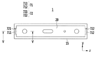
図3は、図1のケースとキャッププレートを分解した部分分解斜視図であり、図4は、図3のケースにキャッププレートを結合した状態の平面図であり、図5は、図4のV−V線に沿った断面図である。 3 is a partially exploded perspective view of the case and cap plate of FIG. 1 disassembled, FIG. 4 is a plan view of the case of FIG. 3 with the cap plate coupled thereto, and FIG. It is sectional drawing along the -V line.
図3〜図5を参照すれば、ケース15は、電極アセンブリ10の挿入される開口面の稜部に少なくとも1つの溝部71を形成し、キャッププレート20は、外周から突出して溝部71に結合される突出部72を形成する。
Referring to FIGS. 3 to 5, the
突出部72の突出長さLは、溝部71のケース15の板厚方向に対応する幅t1よりも小さい。したがって、ケース15にキャッププレート20を設けて溝部71に突出部72を結合すると、溝部71の一部が突出部72の外部に露出する。つまり、溝部71は、突出部72の載置を誘導しながら、溶接可能にする。
The projection length L of the
突出部72の上記キャッププレート20の板厚方向の厚さt2は、溝部71のケース15の開口面に垂直な方向の深さDと同一で、突出部72の上面である外表面とケース15の開口面が平面を形成する。つまり、突出部72と溝部71とが互いに結合された状態で、突出部72とケース15は同一平面を形成し、突出部72が溝部71に過挿入されるのを防止する。
The thickness t2 of the
したがって、本実施形態によれば、キャッププレート20の上面である外表面と、ケース15の開口面は、同一平面に位置する。
Therefore, according to the present embodiment, the outer surface which is the upper surface of the
突出部72は、突出部72の形成されたキャッププレート20の稜部に垂直な断面における形状は、長方形である(図5参照)。したがって、溶接時、突出部72は、溶融して溝部71の周囲で溶接ビード40を大面積に形成することができる。
The
ケース15の開口面およびキャッププレート20は、長方形に形成されるため、一対の長辺と一対の短辺とを有する。溝部71は、ケース15の開口面において、一対の短辺に形成される第1溝711および第2溝712を含む。突出部72は、キャッププレート20において、第1溝711および第2溝712にそれぞれ結合される第1突起721および第2突起722を含む。
The opening surface of the
つまり、第1溝711と第1突起721との結合および第2溝712と第2突起722との結合は、ケース15の開口面でキャッププレート20の結合を誘導し、開口面でキャッププレート20の過挿入を防止する。また、キャッププレート20とケース15とがキャッププレート長手方向であるx軸方向の両側で互いに結合されるため、x軸方向の両側でケース15とキャッププレート20との均衡な結合を可能にする。
That is, the connection between the
ただし、本発明は、キャッププレート20とケース15とが、第1溝711と第1突起721との結合および第2溝712と第2突起722との結合によって結合されることに限定されず、第1溝711と第1突起721、または第2溝712と第2突起722との結合のうちの1つの結合によって結合されることも可能である。
However, the present invention is not limited to the coupling of the
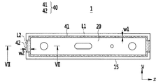
図6は、図4のケースとキャッププレートとを溶接した状態の平面図であり、図7は、図6のVII−VII線に沿った断面図である。図6および図7を参照すれば、ケース15にキャッププレート20を結合して溶接すると、ケース15の内周とキャッププレート20の外周とが互いに接して形成される第1接線L1および第2接線L2に沿って溶接ビード40が形成される。
6 is a plan view of a state in which the case of FIG. 4 and a cap plate are welded, and FIG. 7 is a cross-sectional view taken along the line VII-VII of FIG. 6 and 7, when the
したがって、本実施形態によれば、ケース15とキャッププレート20は、溶接ビード40によって結合できる。
Therefore, according to the present embodiment, the
また、溶接ビード40は、ケース15の少なくとも1つの溝部71とキャッププレート20の少なくとも1つの突出部72とが結合される部分以外の部分に形成される第1ビード41と、少なくとも1つの溝部71とキャッププレート20の少なくとも1つの突出部72とが結合される部分に形成される第2ビード42とを含む。
Further, the
ここで、溶接ビード40は、キャッププレート20の周囲に沿って連続的に形成されることができ、第1ビード41と第2ビード42とは互いに連結されてよい。
Here, the
詳細には、溶接ビード40は、第1線幅W1の第1ビード41と、第2線幅W2の第2ビード42とを含む。第1ビード41は、一対の長辺と一対の短辺で溝部71(または突出部72)の外郭に形成され、第2ビード42は、一対の短辺で溝部71(または突出部72)に対応して形成される。
Specifically, the
第1ビード41は、キャッププレート20がケース15に挿入される時、互いに接する第1接線L1に沿って形成され、第2ビード42は、突出部72が溝部71に接する第2接線L2に沿って形成される。
The
第2ビード42の第2線幅W2は、突出部72の溶融した部分を含んで形成される。したがって、第2線幅W2は第1線幅W1より大きく形成されるため、第2ビード42のキャッププレート20の周囲に沿った方向での単位長さ当たりの面積は、第1ビード41の上記方向での単位長さ当たりの面積より広い。
The second line width W2 of the
つまり、突出部72の溶融した第2ビード42は、短辺でケース15の溝部71とキャッププレート20との溶接強度をさらに増大させることができる。
That is, the melted
以下、本発明の多様な実施形態について説明する。第1実施形態およびすでに説明された実施形態と同一の構成を省略し、互いに異なる構成を説明する。 Hereinafter, various embodiments of the present invention will be described. The same configurations as the first embodiment and the embodiments already described are omitted, and different configurations will be described.
図8は、本発明の第2実施形態にかかる二次電池のケースにキャッププレートを結合した状態の平面図であり、図9は、図8のケースとキャッププレートとを溶接した状態の平面図である。 FIG. 8 is a plan view of a state in which a cap plate is coupled to a case of a secondary battery according to a second embodiment of the present invention, and FIG. 9 is a plan view of a state in which the case of FIG. It is.
図8および図9を参照すれば、第2実施形態にかかる二次電池2において、ケース215の溝部73は、一対の短辺に形成される第1溝711および第2溝712と、一対の長辺に形成される第3溝713および第4溝714とを含む。
8 and 9, in the
キャッププレート220の突出部74は、第1溝711および第2溝712にそれぞれ結合される第1突起721および第2突起722と、第3溝713および第4溝714にそれぞれ結合される第3突起723および第4突起724とを含む。
The
つまり、第1溝711と第1突起721との結合、第2溝712と第2突起722との結合、第3溝713と第3突起723との結合、および第4溝714と第4突起724との結合は、ケース215の開口面でキャッププレート220の結合を誘導し、開口面でキャッププレート220の過挿入を防止する。また、キャッププレート220とケース215とがキャッププレート長手方向であるx軸方向の両側とキャッププレート短手方向であるy軸方向の両側で互いに結合されるため、x軸方向の両側とy軸方向の両側でケース215とキャッププレート20との均衡な結合を可能にする。
That is, the connection between the
溶接ビード240は、第1線幅W1の第1ビード241と、第2線幅W2、W2の第2ビード242、243とを含む。第1ビード241は、一対の短辺で第1溝711(または第1突起721)および第2溝712(または第2突起722)の外郭と、一対の長辺で第3溝713(または第3突起723)および第4溝714(または第4突起724)の外郭に形成される。
The
第2ビード242、243は、一対の短辺で第1溝711(または第1突起721)および第2溝712(または第2突起722)、一対の長辺で第3溝713(または第3突起723)および第4溝714(または第4突起724)に対応して形成される。
第1ビード241は、キャッププレート220がケース215に挿入される時、互いに接する第1接線L21に沿って形成され、第2ビード242、243は、突出部74が溝部73に接する第2接線L22に沿って形成される。
The
The
第2ビード242、243の第2線幅W2は、突出部74の溶融した部分を含んで形成される。したがって、第2線幅W2は、第1線幅W1より大きく形成される。つまり、突出部74の溶融した第2ビード242、243は、短辺と長辺でケース215の溝部73とキャッププレート220との溶接強度をさらに増大させることができる。
The second line width W2 of the
図10は、本発明の第3実施形態にかかる二次電池のケースとキャッププレートを分解した部分分解斜視図であり、図11は、図10のケースにキャッププレートを結合した状態の平面図であり、図12は、図11のケースとキャッププレートとを溶接した状態の平面図であり、図13は、図12のXIII−XIII線に沿った断面図である。 FIG. 10 is a partially exploded perspective view of a case and a cap plate of a secondary battery according to a third embodiment of the present invention, and FIG. 11 is a plan view of the case of FIG. 12 is a plan view of a state in which the case of FIG. 11 and a cap plate are welded, and FIG. 13 is a cross-sectional view taken along line XIII-XIII of FIG.
図11〜図13を参照すれば、第3実施形態にかかる二次電池3において、キャッププレート320の突出部75のキャッププレート320の板厚方向の厚さt32は、溝部71のケース15の開口面に垂直な方向の深さDと同一になってから、漸進的に小さくなる。つまり、突出部75は、キャッププレート320の隣接側で厚く、遠ざかるほど薄くなる。例えば、突出部75は、突出部75が形成されたキャッププレート320の稜部に垂直な断面における形状は、直角三角形である。
11 to 13, in the
キャッププレート320の突出部75は、第1溝711および第2溝712にそれぞれ結合される第1突起751および第2突起752を含む。つまり、第1溝711と第1突起751との結合および第2溝712と第2突起752との結合は、ケース15の開口面でキャッププレート320の結合を誘導し、開口面でキャッププレート320の過挿入を防止する。また、キャッププレート320とケース15とがキャッププレート長手方向であるx軸方向の両側で互いに結合されるため、x軸方向の両側でケース15とキャッププレート320との均衡な結合を可能にする。
The
溶接ビード340は、第1線幅W1の第1ビード41と、第2線幅W32の第2ビード342とを含む。第1ビード41は、一対の長辺と一対の短辺で溝部71(または突出部75)の外郭に形成され、第2ビード342は、一対の短辺で溝部71(または突出部75)に対応して形成される。
The
第1ビード41は、キャッププレート320がケース15に挿入される時、互いに接する第1接線L1に沿って形成され、第2ビード342は、突出部75が溝部71に接する第2接線L32に沿って形成される。
The
第2ビード342の第2線幅W32は、突出部75の溶融した部分を含んで形成される。したがって、第2線幅W32は、第1線幅W1より大きく形成される。つまり、突出部75の溶融した第2ビード342は、短辺でケース15の溝部71とキャッププレート320との溶接強度をさらに増大させることができる。
The second line width W32 of the
図14は、本発明の第4実施形態にかかる二次電池のケースとキャッププレートを分解した部分分解斜視図であり、図15は、図14のケースにキャッププレートを結合した状態の平面図であり、図16は、図15のケースとキャッププレートとを溶接した状態の平面図である。 FIG. 14 is a partially exploded perspective view of a case and a cap plate of a secondary battery according to a fourth embodiment of the present invention, and FIG. 15 is a plan view of the case of FIG. 16 is a plan view of a state in which the case of FIG. 15 and a cap plate are welded.
図14〜図16を参照すれば、第4実施形態にかかる二次電池4において、ケース415の溝部76は、複数の溝および突起で形成され、キャッププレート420の突出部77は、溝部76の複数の溝および突起に対応して結合されるように、複数の突起および溝で形成される。
14 to 16, in the
溝部76と突出部77は、互いに結合されるケース415およびキャッププレート420の長方形において、一対の短辺に形成される第1、第2溝部761、762と、第1、第2突出部771、772とを含む。図示しないが、溝部と突出部は、互いに結合されるケースおよびキャッププレートの長方形において、一対の長辺に形成されるか、一対の長辺と一対の短辺に形成されるか、角に形成されてもよい。
The
つまり、第1溝部761と第1突出部771との結合、第2溝部762と第2突出部772との結合は、ケース415の開口面でキャッププレート420の結合を誘導し、開口面でキャッププレート420の過挿入を防止する。また、キャッププレート420とケース415とがキャッププレート長手方向であるx軸方向の両側で互いに結合されるため、x軸方向の両側でケース415とキャッププレート420との均衡な結合を可能にする。
That is, the connection between the
溶接ビード440は、第1線幅W1の第1ビード41と、第2線幅W42の第2ビード442とを含む。第1ビード41は、一対の長辺に形成され、第2ビード442は、一対の短辺で第1溝部761(または第1突出部771)および第2溝部762(または第2突出部772)に対応して形成される。
The
第1ビード41は、キャッププレート420がケース415に挿入される時、互いに接する第1接線L1に沿って形成され、第2ビード442は、突出部77が溝部76に接する第2接線L42に沿って形成される。
The
第2ビード442の第2線幅W42は、突出部77および溝部76の溶融した部分を含んで形成される。したがって、第2線幅W42は、第1線幅W1より大きく形成される。つまり、突出部77および溝部76の溶融した第2ビード442は、短辺でケース415の溝部76とキャッププレート420との溶接強度をさらに増大させることができる。
The second line width W42 of the
以上、添付図面を参照しながら本発明の好適な実施形態について詳細に説明したが、本発明はかかる例に限定されない。本発明の属する技術の分野における通常の知識を有する者であれば、特許請求の範囲に記載された技術的思想の範疇内において、各種の変更例または修正例に想到し得ることは明らかであり、これらについても、当然に本発明の技術的範囲に属するものと了解される。 Although the preferred embodiments of the present invention have been described in detail with reference to the accompanying drawings, the present invention is not limited to such examples. It is obvious that those skilled in the art to which the present invention belongs can conceive of various changes or modifications within the scope of the technical idea described in the claims. Of course, it is understood that these also fall within the technical scope of the present invention.
1、2、3、4:二次電池
10:電極アセンブリ
11:負極
11a、12a:コーティング部
11b、12b:無地部
12:正極
13:セパレータ
15、215、415:ケース
20、220、320、420:キャッププレート
21、22:電極端子
21a、22a:リベットターミナル
21b、22b:フランジ
21c、22c:プレートターミナル
24:ベントホール
25:ベントプレート
25a:切欠
27:電解液注入口
29:密封キャップ
31、61、62:絶縁部材
32:トッププレート
36、37:ガスケット
40、240、340、440:溶接ビード
41、241:第1ビード
42、242、243、342、442:第2ビード
51、52:リードタブ
71、73、76:溝部
72、74、75、77:突出部
711、712:第1、第2溝
713、714:第3、第4溝
721、751:第1突起
722、752:第2突起
723、724:第3、第4突起
761、762:第1、第2溝部
771、772:第1、第2突出部
D:深さ
H1、H2:端子ホール
H3、H4:貫通ホール
L:突出長さ
L1、L21:第1接線
L2、L22、L32、L42:第2接線
t1:幅
t2、t32:厚さ
W1:第1線幅
W2、W32、W42:第2線幅
1, 2, 3, 4: Secondary battery 10: Electrode assembly 11: Negative electrode 11a, 12a: Coating portion 11b, 12b: Solid portion 12: Positive electrode 13: Separator 15, 215, 415: Case 20, 220, 320, 420 A: Cap plate 21, 22: Electrode terminal 21a, 22a: Rivet terminal 21b, 22b: Flange 21c, 22c: Plate terminal 24: Vent hole 25: Vent plate 25a: Notch 27: Electrolyte inlet 29: Sealing cap 31, 61 , 62: insulating member 32: top plate 36, 37: gasket 40, 240, 340, 440: weld bead 41, 241: first bead 42, 242, 243, 342, 442: second bead 51, 52: lead tab 71 , 73, 76: grooves 72, 74, 75, 7 Protrusions 711 and 712: first and second grooves 713 and 714: third and fourth grooves 721 and 751: first protrusions 722 and 752: second protrusions 722 and 724: third and fourth protrusions 761 and 762 A: first and second grooves 771 and 772: first and second protrusions D: depth H1 and H2: terminal holes H3 and H4: through holes L: protrusion length L1 and L21: first tangent L2 and L22; L32, L42: second tangent t1: width t2, t32: thickness W1: first line width W2, W32, W42: second line width
Claims (17)
前記電極アセンブリの挿入される開口面の稜部に形成された少なくとも1つの溝部を含むケースと、
前記ケースの前記稜部に形成された前記少なくとも1つの溝部に結合される少なくとも1つの突出部を含むキャッププレートと、
を含み、
前記ケースの開口面及び前記キャッププレートは、一対の長辺と一対の短辺とを含み、
前記少なくとも1つの溝部は、前記ケースの開口面のいずれかの辺の一部に形成され、
前記少なくとも1つの突出部は、前記キャッププレートのいずれかの辺の一部に形成されることを特徴とする、二次電池。 An electrode assembly comprising a first electrode, a second electrode, and a separator interposed between the first electrode and the second electrode;
A case including at least one groove formed in a ridge of an opening face into which the electrode assembly is inserted;
A cap plate including at least one protrusion coupled to the at least one groove formed in the ridge of the case;
Including
The opening surface of the case and the cap plate include a pair of long sides and a pair of short sides,
The at least one groove is formed in part of any side of the opening surface of the case,
The secondary battery, wherein the at least one protrusion is formed on a part of either side of the cap plate.
長方形状または台形形状であることを特徴とする、請求項1に記載の二次電池。 The cap plate is
The secondary battery according to claim 1, wherein the secondary battery is rectangular or trapezoidal.
前記キャッププレートの前記一対の短辺のうちの少なくとも1つに形成されることを特徴とする、請求項1または2のいずれかに記載の二次電池。 The at least one projection is
The secondary battery according to claim 1, wherein the secondary battery is formed on at least one of the pair of short sides of the cap plate.
前記キャッププレートの前記一対の長辺のうちの少なくとも1つに形成されることを特徴とする、請求項1〜3のいずれかに記載の二次電池。 The at least one projection is
The secondary battery according to any one of claims 1 to 3, wherein the secondary battery is formed on at least one of the pair of long sides of the cap plate.
前記キャッププレートの外表面は、前記ケースの開口面と同一平面に位置することを特徴とする、請求項1〜5のいずれかに記載の二次電池。 The thickness of the at least one protrusion in the thickness direction of the cap plate is substantially the same as the depth of the at least one groove in the direction perpendicular to the opening surface of the case,
The secondary battery according to any one of claims 1 to 5, wherein an outer surface of the cap plate is flush with an opening surface of the case.
前記溶接ビードは、
前記ケースの前記少なくとも1つの溝部と前記キャッププレートの前記少なくとも1つの突出部とが結合される部分以外の部分に形成される第1ビードと、
前記少なくとも1つの溝部と前記キャッププレートの前記少なくとも1つの突出部とが結合される部分に形成される第2ビードと、
を含むことを特徴とする、請求項1〜7のいずれかに記載の二次電池。 It further includes a weld bead for joining the case and the cap plate,
The weld bead is
A first bead formed in a portion other than a portion where the at least one groove portion of the case and the at least one protrusion portion of the cap plate are coupled;
A second bead formed in a portion where the at least one groove and the at least one protrusion of the cap plate are joined;
The secondary battery according to any one of claims 1 to 7, comprising:
前記少なくとも1つの突出部の一部を含むことを特徴とする、請求項8〜10のいずれかに記載の二次電池。 The second bead is
The secondary battery according to any one of claims 8 to 10, comprising a part of the at least one protrusion.
前記キャッププレートの中央から外周へ向かう方向に厚さが薄くなることを特徴とする、請求項1〜6のいずれかに記載の二次電池。 The at least one projection is
The secondary battery according to any one of claims 1 to 6, wherein the thickness decreases in a direction from the center to the outer periphery of the cap plate.
前記少なくとも1つの溝部は、当該複数の突起および溝に対応して結合される複数の溝および突起を含むことを特徴とする、請求項1〜12のいずれかに記載の二次電池。 The at least one protrusion includes a plurality of protrusions and grooves ,
The secondary battery according to any one of claims 1 to 12, wherein the at least one groove includes a plurality of grooves and protrusions coupled to the plurality of protrusions and grooves .
前記キャッププレートに結合され、前記第2電極に電気的に連結される第2電極端子とをさらに含むことを特徴とする、請求項1〜13のいずれかに記載の二次電池。 A first electrode terminal coupled to the cap plate and electrically connected to the first electrode;
The secondary battery according to any one of claims 1 to 13, further comprising: a second electrode terminal coupled to the cap plate and electrically connected to the second electrode.
ベントホールと、前記ベントホールを密閉するベントプレートとをさらに含むことを特徴とする、請求項1〜14のいずれかに記載の二次電池。 The cap plate is
The secondary battery according to any one of claims 1 to 14, further comprising a vent hole and a vent plate sealing the vent hole.
Applications Claiming Priority (4)
| Application Number | Priority Date | Filing Date | Title |
|---|---|---|---|
| US201361856269P | 2013-07-19 | 2013-07-19 | |
| US61/856,269 | 2013-07-19 | ||
| US14/166,693 US9515297B2 (en) | 2013-07-19 | 2014-01-28 | Rechargeable battery |
| US14/166,693 | 2014-01-28 |
Publications (2)
| Publication Number | Publication Date |
|---|---|
| JP2015023025A JP2015023025A (en) | 2015-02-02 |
| JP6518042B2 true JP6518042B2 (en) | 2019-05-22 |
Family
ID=50031228
Family Applications (1)
| Application Number | Title | Priority Date | Filing Date |
|---|---|---|---|
| JP2014134233A Active JP6518042B2 (en) | 2013-07-19 | 2014-06-30 | Secondary battery |
Country Status (5)
| Country | Link |
|---|---|
| US (1) | US9515297B2 (en) |
| EP (1) | EP2827399B1 (en) |
| JP (1) | JP6518042B2 (en) |
| KR (1) | KR102211173B1 (en) |
| CN (1) | CN104300171B (en) |
Families Citing this family (17)
| Publication number | Priority date | Publication date | Assignee | Title |
|---|---|---|---|---|
| WO2015157295A1 (en) * | 2014-04-08 | 2015-10-15 | Capital One Financial Corporation | Systems and methods for transacting at an atm using a mobile device |
| US11020820B2 (en) * | 2014-04-15 | 2021-06-01 | Panasonic Intellectual Property Management Co., Ltd. | Laser welding method |
| KR102423894B1 (en) * | 2015-05-19 | 2022-07-20 | 삼성에스디아이 주식회사 | Rechargeable battery |
| JP6213784B2 (en) * | 2015-06-12 | 2017-10-18 | トヨタ自動車株式会社 | Sealed battery |
| US10275588B2 (en) * | 2016-03-08 | 2019-04-30 | Ca, Inc. | Providing multi-factor security for electronic devices through body area network and radiofrequency network communications |
| JP6725351B2 (en) | 2016-07-14 | 2020-07-15 | 株式会社Gsユアサ | Electric storage element and method for manufacturing electric storage element |
| KR102611656B1 (en) * | 2016-08-30 | 2023-12-08 | 삼성에스디아이 주식회사 | Secondary battery |
| KR102201278B1 (en) * | 2016-09-19 | 2021-01-08 | 삼성에스디아이 주식회사 | Rechargeable battery |
| KR102422513B1 (en) * | 2016-10-24 | 2022-07-20 | 삼성에스디아이 주식회사 | Secondary Battery |
| CN108054302A (en) * | 2017-11-17 | 2018-05-18 | 深圳市瑞德丰精密制造有限公司 | The Joining Technology of lamina tecti and housing |
| KR102292722B1 (en) * | 2017-12-20 | 2021-08-20 | 주식회사 엘지에너지솔루션 | Battery module, battery pack comprising the battery module |
| KR102353921B1 (en) * | 2018-01-12 | 2022-01-20 | 주식회사 엘지에너지솔루션 | Battery module, battery pack and vehicle comprising the same |
| KR102232080B1 (en) * | 2019-04-09 | 2021-03-26 | 선광엘티아이(주) | Metal air fuel cell for high power generation systems |
| KR20220048373A (en) * | 2020-10-12 | 2022-04-19 | 주식회사 엘지에너지솔루션 | Button type secondary battery |
| CN214505621U (en) * | 2021-03-29 | 2021-10-26 | 宁德时代新能源科技股份有限公司 | Battery monomer, battery and use device of battery monomer as power |
| CN115347284A (en) * | 2021-05-14 | 2022-11-15 | 中创新航科技股份有限公司 | Battery manufacturing method and battery |
| KR20230060813A (en) * | 2021-10-28 | 2023-05-08 | (주) 에스피시스템스 | Side structure of battery pack for automotive secondary battery |
Family Cites Families (9)
| Publication number | Priority date | Publication date | Assignee | Title |
|---|---|---|---|---|
| JPH10144268A (en) | 1996-11-08 | 1998-05-29 | Mitsubishi Cable Ind Ltd | Sealing structure for sealed battery |
| EP0973211A4 (en) | 1997-11-07 | 2004-05-26 | Sony Corp | Square-shape closed battery |
| JP2001155698A (en) | 1999-11-29 | 2001-06-08 | Nec Mobile Energy Kk | Encapsulated type battery |
| JP2004195490A (en) | 2002-12-17 | 2004-07-15 | Toyota Motor Corp | Weldment and method for manufacturing the same |
| KR20070092696A (en) | 2004-07-07 | 2007-09-13 | 아이큐 파워 라이센싱 아게 | Vehicle battery arrangement comprising electronic components |
| KR100965718B1 (en) | 2008-10-08 | 2010-06-24 | 삼성에스디아이 주식회사 | Secondary Battery |
| KR101142600B1 (en) | 2009-09-15 | 2012-05-03 | 삼성에스디아이 주식회사 | Secondary battery |
| JP5504007B2 (en) | 2010-02-26 | 2014-05-28 | 日立ビークルエナジー株式会社 | Square battery and method for manufacturing the same |
| JP2013114798A (en) * | 2011-11-25 | 2013-06-10 | Toyota Motor Corp | Sealed battery and method of manufacturing sealed battery |
-
2014
- 2014-01-28 US US14/166,693 patent/US9515297B2/en active Active
- 2014-02-04 EP EP14153791.0A patent/EP2827399B1/en active Active
- 2014-04-30 KR KR1020140052435A patent/KR102211173B1/en active IP Right Grant
- 2014-06-30 JP JP2014134233A patent/JP6518042B2/en active Active
- 2014-07-08 CN CN201410323083.8A patent/CN104300171B/en active Active
Also Published As
| Publication number | Publication date |
|---|---|
| CN104300171B (en) | 2020-12-04 |
| EP2827399A2 (en) | 2015-01-21 |
| CN104300171A (en) | 2015-01-21 |
| EP2827399B1 (en) | 2018-11-07 |
| US9515297B2 (en) | 2016-12-06 |
| US20150024260A1 (en) | 2015-01-22 |
| JP2015023025A (en) | 2015-02-02 |
| KR20150010569A (en) | 2015-01-28 |
| EP2827399A3 (en) | 2015-03-25 |
| KR102211173B1 (en) | 2021-02-01 |
Similar Documents
| Publication | Publication Date | Title |
|---|---|---|
| JP6518042B2 (en) | Secondary battery | |
| KR102273643B1 (en) | Rechargeable battery | |
| JP6444064B2 (en) | Secondary battery | |
| JP6523624B2 (en) | Secondary battery | |
| US10388939B2 (en) | Secondary battery | |
| US9819002B2 (en) | Rechargeable battery and rechargeable battery module including the same | |
| JP6679204B2 (en) | Rechargeable battery | |
| KR102284572B1 (en) | Rechargeable battery | |
| KR102299244B1 (en) | Rechargeable battery and pack of the same | |
| JP5225805B2 (en) | Secondary battery and manufacturing method thereof | |
| US9799874B2 (en) | Rechargeable battery | |
| KR102467002B1 (en) | Rechargeable battery | |
| KR102360013B1 (en) | Rechargeable battery | |
| KR101724001B1 (en) | Rechargeable battery | |
| KR102368087B1 (en) | Rechargeable battery | |
| KR102361706B1 (en) | Rechargeable battery | |
| JP6094880B2 (en) | Power storage device | |
| JP6715936B2 (en) | Prismatic secondary battery | |
| KR102314084B1 (en) | Secondary battery | |
| KR102119048B1 (en) | Rechargeable battery | |
| KR20180001063A (en) | Rechargeable battery | |
| JP2019012638A (en) | Power storage device and manufacturing method thereof |
Legal Events
| Date | Code | Title | Description |
|---|---|---|---|
| A621 | Written request for application examination |
Free format text: JAPANESE INTERMEDIATE CODE: A621 Effective date: 20170619 |
|
| A977 | Report on retrieval |
Free format text: JAPANESE INTERMEDIATE CODE: A971007 Effective date: 20180326 |
|
| A131 | Notification of reasons for refusal |
Free format text: JAPANESE INTERMEDIATE CODE: A131 Effective date: 20180403 |
|
| A521 | Request for written amendment filed |
Free format text: JAPANESE INTERMEDIATE CODE: A523 Effective date: 20180625 |
|
| A131 | Notification of reasons for refusal |
Free format text: JAPANESE INTERMEDIATE CODE: A131 Effective date: 20181016 |
|
| A521 | Request for written amendment filed |
Free format text: JAPANESE INTERMEDIATE CODE: A523 Effective date: 20190109 |
|
| TRDD | Decision of grant or rejection written | ||
| A01 | Written decision to grant a patent or to grant a registration (utility model) |
Free format text: JAPANESE INTERMEDIATE CODE: A01 Effective date: 20190326 |
|
| A61 | First payment of annual fees (during grant procedure) |
Free format text: JAPANESE INTERMEDIATE CODE: A61 Effective date: 20190419 |
|
| R150 | Certificate of patent or registration of utility model |
Ref document number: 6518042 Country of ref document: JP Free format text: JAPANESE INTERMEDIATE CODE: R150 |
|
| R250 | Receipt of annual fees |
Free format text: JAPANESE INTERMEDIATE CODE: R250 |
|
| R250 | Receipt of annual fees |
Free format text: JAPANESE INTERMEDIATE CODE: R250 |