JP2014190669A - Solar light/heat hybrid panel and solar system - Google Patents

Solar light/heat hybrid panel and solar system Download PDF

Info

Publication number
JP2014190669A
JP2014190669A JP2013069100A JP2013069100A JP2014190669A JP 2014190669 A JP2014190669 A JP 2014190669A JP 2013069100 A JP2013069100 A JP 2013069100A JP 2013069100 A JP2013069100 A JP 2013069100A JP 2014190669 A JP2014190669 A JP 2014190669A
Authority
JP
Japan
Prior art keywords
solar
heat
power generation
heat medium
panel
Prior art date
Legal status (The legal status is an assumption and is not a legal conclusion. Google has not performed a legal analysis and makes no representation as to the accuracy of the status listed.)
Pending
Application number
JP2013069100A
Other languages
Japanese (ja)
Inventor
Takumi Nishiyama
拓未 西山
Satoshi Akagi
智 赤木
Fumitake Unezaki
史武 畝崎
Current Assignee (The listed assignees may be inaccurate. Google has not performed a legal analysis and makes no representation or warranty as to the accuracy of the list.)
Mitsubishi Electric Corp
Original Assignee
Mitsubishi Electric Corp
Priority date (The priority date is an assumption and is not a legal conclusion. Google has not performed a legal analysis and makes no representation as to the accuracy of the date listed.)
Filing date
Publication date
Application filed by Mitsubishi Electric Corp filed Critical Mitsubishi Electric Corp
Priority to JP2013069100A priority Critical patent/JP2014190669A/en
Publication of JP2014190669A publication Critical patent/JP2014190669A/en
Pending legal-status Critical Current

Links

Images

Classifications

    • FMECHANICAL ENGINEERING; LIGHTING; HEATING; WEAPONS; BLASTING
    • F24HEATING; RANGES; VENTILATING
    • F24SSOLAR HEAT COLLECTORS; SOLAR HEAT SYSTEMS
    • F24S10/00Solar heat collectors using working fluids
    • F24S10/50Solar heat collectors using working fluids the working fluids being conveyed between plates
    • F24S10/502Solar heat collectors using working fluids the working fluids being conveyed between plates having conduits formed by paired plates and internal partition means
    • FMECHANICAL ENGINEERING; LIGHTING; HEATING; WEAPONS; BLASTING
    • F24HEATING; RANGES; VENTILATING
    • F24SSOLAR HEAT COLLECTORS; SOLAR HEAT SYSTEMS
    • F24S80/00Details, accessories or component parts of solar heat collectors not provided for in groups F24S10/00-F24S70/00
    • F24S80/30Arrangements for connecting the fluid circuits of solar collectors with each other or with other components, e.g. pipe connections; Fluid distributing means, e.g. headers
    • YGENERAL TAGGING OF NEW TECHNOLOGICAL DEVELOPMENTS; GENERAL TAGGING OF CROSS-SECTIONAL TECHNOLOGIES SPANNING OVER SEVERAL SECTIONS OF THE IPC; TECHNICAL SUBJECTS COVERED BY FORMER USPC CROSS-REFERENCE ART COLLECTIONS [XRACs] AND DIGESTS
    • Y02TECHNOLOGIES OR APPLICATIONS FOR MITIGATION OR ADAPTATION AGAINST CLIMATE CHANGE
    • Y02BCLIMATE CHANGE MITIGATION TECHNOLOGIES RELATED TO BUILDINGS, e.g. HOUSING, HOUSE APPLIANCES OR RELATED END-USER APPLICATIONS
    • Y02B10/00Integration of renewable energy sources in buildings
    • Y02B10/10Photovoltaic [PV]
    • YGENERAL TAGGING OF NEW TECHNOLOGICAL DEVELOPMENTS; GENERAL TAGGING OF CROSS-SECTIONAL TECHNOLOGIES SPANNING OVER SEVERAL SECTIONS OF THE IPC; TECHNICAL SUBJECTS COVERED BY FORMER USPC CROSS-REFERENCE ART COLLECTIONS [XRACs] AND DIGESTS
    • Y02TECHNOLOGIES OR APPLICATIONS FOR MITIGATION OR ADAPTATION AGAINST CLIMATE CHANGE
    • Y02BCLIMATE CHANGE MITIGATION TECHNOLOGIES RELATED TO BUILDINGS, e.g. HOUSING, HOUSE APPLIANCES OR RELATED END-USER APPLICATIONS
    • Y02B10/00Integration of renewable energy sources in buildings
    • Y02B10/20Solar thermal
    • YGENERAL TAGGING OF NEW TECHNOLOGICAL DEVELOPMENTS; GENERAL TAGGING OF CROSS-SECTIONAL TECHNOLOGIES SPANNING OVER SEVERAL SECTIONS OF THE IPC; TECHNICAL SUBJECTS COVERED BY FORMER USPC CROSS-REFERENCE ART COLLECTIONS [XRACs] AND DIGESTS
    • Y02TECHNOLOGIES OR APPLICATIONS FOR MITIGATION OR ADAPTATION AGAINST CLIMATE CHANGE
    • Y02EREDUCTION OF GREENHOUSE GAS [GHG] EMISSIONS, RELATED TO ENERGY GENERATION, TRANSMISSION OR DISTRIBUTION
    • Y02E10/00Energy generation through renewable energy sources
    • Y02E10/40Solar thermal energy, e.g. solar towers
    • Y02E10/44Heat exchange systems

Landscapes

  • Engineering & Computer Science (AREA)
  • Physics & Mathematics (AREA)
  • Life Sciences & Earth Sciences (AREA)
  • Sustainable Development (AREA)
  • Sustainable Energy (AREA)
  • Thermal Sciences (AREA)
  • Chemical & Material Sciences (AREA)
  • Combustion & Propulsion (AREA)
  • Mechanical Engineering (AREA)
  • General Engineering & Computer Science (AREA)
  • Photovoltaic Devices (AREA)

Abstract

PROBLEM TO BE SOLVED: To adapt to various dimensions and shapes of a photovoltaic power generation panel easily, and to execute power generation and cooling efficiently by suppressing deformation of a panel.SOLUTION: A solar light/heat hybrid panel 1 comprises: a photovoltaic power generation panel 2; solar battery cells 3; solar heat collectors 4; communication pipes 10; a heating medium introduction pipe 11; and a heating medium lead-out pipe 12 and the like. In the solar heat collector 4, a heating medium flow passage 7 where a heat recovery medium circulates is provided, and the heating medium flow passage 7 of each solar heat collector 4 is communicated by the communication pipe 10. Also, the plurality of solar heat collectors 4 are arranged by aligning two or more of them respectively along two directions parallel with a rear surface of the photovoltaic power generation panel 2 and orthogonal to each other. Thereby, a plurality of kinds of solar light/heat hybrid panels 1 and 21 can be assembled with one kind of the solar heat collector 4 being a common component. Also, deformation such as warping, deflection and the like generating in the photovoltaic power generation panel 2 can be suppressed, and power generation efficiency can be improved.

Description

本発明は、太陽光発電パネルと太陽熱収集器とを備えた太陽光熱ハイブリッドパネル及び該太陽光熱ハイブリッドパネルを用いたソーラーシステムに関する。   The present invention relates to a solar thermal hybrid panel including a solar power generation panel and a solar heat collector, and a solar system using the solar thermal hybrid panel.

従来技術として、例えば特開2004−198093号公報に記載されているように、四角形状の太陽電池パネルと集熱パネルとを重ね合わせた状態で一体化し、太陽光発電及び太陽光からの集熱を実行する構成とした混成型太陽熱集熱パネルが知られている。従来技術では、複数個の細長い集熱部材を組合わせることにより、太陽光発電パネルと同程度の大きさをもつ四角形状の集熱パネルを形成している。   As a conventional technique, for example, as described in Japanese Patent Application Laid-Open No. 2004-198093, a rectangular solar cell panel and a heat collection panel are integrated in a superimposed state, and solar power generation and heat collection from sunlight are performed. There is known a hybrid solar heat collecting panel configured to execute the above. In the prior art, a rectangular heat collecting panel having the same size as the photovoltaic power generation panel is formed by combining a plurality of elongated heat collecting members.

詳しく述べると、太陽光発電パネルの四辺のうち互いに直交する二辺の寸法を長さ寸法及び幅寸法と定義した場合に、集熱部材は、太陽光発電パネルと同程度の長さ寸法と、太陽光発電パネルよりも短尺な幅寸法とを有する細長い板材として形成されている。そして、従来技術では、複数個の集熱部材を幅方向の端部が隣接するように平板状に並べた状態で組合わせることにより、1枚の集熱パネルを形成している。   More specifically, when the dimensions of two sides orthogonal to each other among the four sides of the photovoltaic power generation panel are defined as the length dimension and the width dimension, the heat collecting member has the same length dimension as the photovoltaic power generation panel, It is formed as an elongated plate having a width dimension shorter than that of the photovoltaic power generation panel. In the prior art, a single heat collecting panel is formed by combining a plurality of heat collecting members in a state of being arranged in a flat plate shape so that end portions in the width direction are adjacent to each other.

特開2004−198093号公報(第13頁、第9図)JP 2004-198093 A (page 13, FIG. 9)

上述した従来技術では、複数個の細長い集熱部材を平板状に並べた状態で組合わせることにより、太陽光発電パネルと同程度の大きさをもつ集熱パネルを形成している。しかしながら、太陽光発電パネルの外形寸法には、例えば1.6m×0.8m程度の一般的な寸法だけでなく、規格外の寸法が存在し得る。また、太陽光発電パネルの形状にも、四角形だけでなく、台形等のような規格外の形状が存在する。このため、従来技術では、太陽光発電パネルの寸法または形状が規格外である場合に、これに合わせて専用の集熱器を製造する必要があり、設計及び製造の効率が低下するという問題がある。   In the prior art described above, a heat collecting panel having a size similar to that of the photovoltaic power generation panel is formed by combining a plurality of elongated heat collecting members in a flat plate shape. However, the outer dimensions of the photovoltaic power generation panel may include not only a general dimension of, for example, about 1.6 m × 0.8 m, but also a non-standard dimension. In addition, the shape of the photovoltaic power generation panel includes not only a quadrangle but also a non-standard shape such as a trapezoid. For this reason, in the prior art, when the size or shape of the photovoltaic power generation panel is out of the standard, it is necessary to manufacture a dedicated heat collector according to this, and there is a problem in that the efficiency of design and manufacturing decreases. is there.

また、従来技術のように、太陽光発電パネルの長さ方向にのみ伸長した複数個の集熱部材を組合わせて集熱パネルを形成すると、集熱パネルが自重により長さ方向に撓み変形し易くなり、太陽光発電パネルと集熱パネルとの間に隙間が生じることがある。この状態を回避するためには、例えば集熱パネルを太陽光発電パネルに押し付けて密着状態に保持する矯正梁等の補強部材が必要となるという問題がある。   Also, as in the prior art, when a heat collection panel is formed by combining a plurality of heat collection members that extend only in the length direction of the photovoltaic power generation panel, the heat collection panel bends and deforms in the length direction due to its own weight. It becomes easy, and a clearance gap may arise between a photovoltaic power generation panel and a heat collecting panel. In order to avoid this state, for example, there is a problem that a reinforcing member such as a straight beam that presses the heat collecting panel against the photovoltaic power generation panel and keeps it in a close contact state is required.

また、集熱パネルは、日照時の温度上昇により熱膨張するが、集熱部材の寸法が一方向にのみ大きいと、集熱パネルの部位によって熱膨張量に偏差が生じ易くなり、パネルの反り、撓み等の変形を誘発するという問題がある。一例を挙げると、集熱部材が長さ1.6m×幅0.2m×厚さ4mm程度のアクリル樹脂板により形成され、長さ方向の両端部のみを支持されている場合には、集熱部材の最大撓み量は50mmに達する。   In addition, the heat collection panel thermally expands due to a rise in temperature during sunshine. However, if the heat collection member has a large dimension in only one direction, the thermal expansion amount tends to vary depending on the heat collection panel area, and the panel warp. There is a problem of inducing deformation such as bending. For example, when the heat collecting member is formed of an acrylic resin plate having a length of about 1.6 m, a width of 0.2 m, and a thickness of about 4 mm, and only the both ends in the length direction are supported, The maximum deflection of the member reaches 50 mm.

本発明は、上述のような課題を解決するためになされたもので、太陽光発電パネルの多様な寸法及び形状に対して容易に適応することができ、また、パネルの変形を抑制して発電及び冷却を効率よく実行することが可能な太陽光熱ハイブリッドパネル及びソーラーシステムを提供することを目的とする。   The present invention has been made to solve the above-described problems, and can be easily adapted to various sizes and shapes of the photovoltaic power generation panel, and can generate power by suppressing deformation of the panel. And it aims at providing the solar thermal hybrid panel and solar system which can perform cooling efficiently.

本発明に係る太陽光熱ハイブリッドパネルは、太陽光を受けて発電する複数個の太陽電池セルが表面側に並べて配置された板状の太陽光発電パネルと、太陽光発電パネルの裏面の面積範囲内に収まるように当該裏面側に並べて配置され、太陽光発電パネルの裏面と平行で互いに直交する2方向に沿ってそれぞれ2つ以上並べられた複数個の太陽熱収集器と、複数個の太陽熱収集器にそれぞれ設けられ、熱回収媒体が流通する熱媒体流路と、複数個の太陽熱収集器の熱媒体流路同士を連通する連通管と、を備えている。   The solar thermal hybrid panel according to the present invention includes a plate-shaped photovoltaic power generation panel in which a plurality of photovoltaic cells that generate sunlight and generate power are arranged side by side, and within the area range of the back surface of the photovoltaic power generation panel. A plurality of solar heat collectors arranged side by side on the back surface side so as to fit in, and two or more solar heat collectors arranged in two directions parallel to and orthogonal to the back surface of the photovoltaic power generation panel, and a plurality of solar heat collectors And a heat medium passage through which the heat recovery medium flows, and a communication pipe communicating the heat medium passages of the plurality of solar heat collectors.

本発明によれば、複数個の太陽熱収集器を太陽光発電パネルの裏面に沿って2方向に並べるので、形状または寸法が異なる複数種類の太陽光発電パネルが存在する場合でも、太陽熱収集器の並べ方及び並べる個数等を変更することにより対応することができる。即ち、1種類の太陽熱収集器を共通な部品として、複数種類の太陽光熱ハイブリッドパネルを組立てることができる。従って、太陽光熱ハイブリッドパネルの製品ラインナップ全体において、太陽熱収集器等の部品点数を削減し、製造効率を高めて製造コストを抑制することができる。また、複数個の太陽熱収集器を直交する2方向に沿って並べるので、太陽光発電パネルに生じる反り、撓み等の変形を抑制し、太陽光発電パネルと太陽熱収集器との間の密着度を高めることができる。これにより、太陽電池セルを効率よく冷却し、太陽光発電パネルの発電効率及び発電量を向上させることができる。   According to the present invention, since a plurality of solar collectors are arranged in two directions along the back surface of the photovoltaic power generation panel, even when there are a plurality of types of photovoltaic power generation panels having different shapes or dimensions, This can be dealt with by changing the arrangement method and the number of arrangement items. That is, a plurality of types of solar thermal hybrid panels can be assembled using one type of solar heat collector as a common part. Therefore, in the entire product lineup of solar thermal hybrid panels, the number of parts such as solar heat collectors can be reduced, the manufacturing efficiency can be increased, and the manufacturing cost can be suppressed. In addition, since a plurality of solar heat collectors are arranged along two orthogonal directions, deformations such as warping and bending that occur in the solar power generation panel are suppressed, and the degree of adhesion between the solar power generation panel and the solar heat collector is improved. Can be increased. Thereby, a photovoltaic cell can be cooled efficiently and the power generation efficiency and power generation amount of a solar power generation panel can be improved.

本発明の実施の形態1による太陽光熱ハイブリッドパネルを表面側からみた構成図である。It is the block diagram which looked at the solar thermal hybrid panel by Embodiment 1 of this invention from the surface side. 図1中の太陽光熱ハイブリッドパネルを裏面側からみた構成図である。It is the block diagram which looked at the solar thermal hybrid panel in FIG. 1 from the back surface side. 本発明の実施の形態1において、太陽熱収集器を太陽光発電パネルの表面と垂直な方向に破断した状態を示す縦断面図である。In Embodiment 1 of this invention, it is a longitudinal cross-sectional view which shows the state which fractured | ruptured the solar heat collector in the direction perpendicular | vertical to the surface of a photovoltaic power generation panel. 太陽熱収集器を図3中の矢示A−A方向に沿って破断した状態を示す横断面図である。It is a cross-sectional view which shows the state which fractured | ruptured the solar-heat collector along the arrow AA direction in FIG. 太陽熱収集器の蓋板を図3中の矢示A−A方向からみた単体図である。It is the single figure which looked at the cover plate of the solar heat collector from the arrow AA direction in FIG. 本発明の実施の形態1において、太陽熱収集器と連通管等との接続構造の一例を示す構成図である。In Embodiment 1 of this invention, it is a block diagram which shows an example of the connection structure of a solar-heat collector, a communicating pipe, etc. FIG. 太陽熱収集器と連通管等との接続構造の他の一例を示す構成図である。It is a block diagram which shows another example of the connection structure of a solar-heat collector and a communicating pipe. 本発明の実施の形態1において、規格外の形状または寸法をもつ他の太陽光熱ハイブリッドパネルを構成した場合を示す構成図である。In Embodiment 1 of this invention, it is a block diagram which shows the case where the other solar thermal hybrid panel which has a shape or dimension outside a specification is comprised. 本発明の実施の形態1における変形例を示す図3と同様の縦断面図である。It is the same longitudinal cross-sectional view as FIG. 3 which shows the modification in Embodiment 1 of this invention. 本発明の実施の形態2による太陽光熱ハイブリッドパネルを裏面側からみた構成図である。It is the block diagram which looked at the solar thermal hybrid panel by Embodiment 2 of this invention from the back surface side. 本発明の実施の形態2による太陽熱収集器を図3と同様位置からみた縦断面図である。It is the longitudinal cross-sectional view which looked at the solar heat collector by Embodiment 2 of this invention from the same position as FIG. 太陽熱収集器を図11中の矢示A−A方向に沿って破断した状態を示す横断面図である。It is a cross-sectional view which shows the state which fractured | ruptured the solar-heat collector along the arrow AA direction in FIG. 本発明の実施の形態2において、太陽熱収集器と連通管等との接続構造の一例を示す構成図である。In Embodiment 2 of this invention, it is a block diagram which shows an example of the connection structure of a solar-heat collector, a communicating pipe, etc. FIG. 本発明の実施の形態2において、規格外の形状または寸法をもつ他の太陽光熱ハイブリッドパネルを構成した場合を示す構成図である。In Embodiment 2 of this invention, it is a block diagram which shows the case where the other solar thermal hybrid panel which has a shape or dimension outside a specification is comprised. 本発明の実施の形態2における変形例を示す図3と同様の縦断面図である。It is the same longitudinal cross-sectional view as FIG. 3 which shows the modification in Embodiment 2 of this invention. 本発明の実施の形態3による太陽熱収集器を図3と同様位置からみた縦断面図である。It is the longitudinal cross-sectional view which looked at the solar heat collector by Embodiment 3 of this invention from the same position as FIG. 太陽熱収集器を図16中の矢示A−A方向に沿って破断した状態を示す横断面図である。It is a cross-sectional view which shows the state which fractured | ruptured the solar-heat collector along the arrow AA direction in FIG. 太陽熱収集器の蓋板を図16中の矢示A−A方向からみた単体図である。It is the single figure which looked at the cover plate of the solar heat collector from the arrow AA direction in FIG. 本発明の実施の形態3における変形例を示す図3と同様の縦断面図である。It is the same longitudinal cross-sectional view as FIG. 3 which shows the modification in Embodiment 3 of this invention. 本発明の実施の形態4による太陽光熱ハイブリッドパネルを裏面側からみた構成図である。It is the block diagram which looked at the solar thermal hybrid panel by Embodiment 4 of this invention from the back surface side. 本発明の実施の形態5による太陽光熱ハイブリッドパネルを裏面側からみた構成図である。It is the block diagram which looked at the solar thermal hybrid panel by Embodiment 5 of this invention from the back surface side. 本発明の実施の形態4における変形例を示す図20と同様の構成図である。It is the same structure figure as FIG. 20 which shows the modification in Embodiment 4 of this invention. 本発明の実施の形態5における変形例を示す図21と同様の構成図である。FIG. 22 is a configuration diagram similar to FIG. 21 showing a modification of the fifth embodiment of the present invention. 本発明の実施の形態6において、太陽光熱ハイブリッドパネルの一部及びソーラーシステムを示す構成図である。In Embodiment 6 of this invention, it is a block diagram which shows a part of solar thermal hybrid panel and solar system. 図24中のバイパス機構により熱回収媒体をバイパスさせた状態を示す動作説明図である。It is operation | movement explanatory drawing which shows the state which made the heat recovery medium bypass by the bypass mechanism in FIG. 本発明の実施の形態7による太陽光熱ハイブリッドパネルの一部を拡大して示す部分拡大図である。It is the elements on larger scale which expand and show a part of solar thermal hybrid panel by Embodiment 7 of this invention. 図26中のバイパス機構により熱回収媒体をバイパスさせた状態を示す動作説明図である。It is operation | movement explanatory drawing which shows the state which made the heat recovery medium bypass by the bypass mechanism in FIG. 図26中のバイパス機構により熱回収媒体をバイパスさせた他の状態を示す動作説明図である。It is operation | movement explanatory drawing which shows the other state which made the heat recovery medium bypass by the bypass mechanism in FIG.

実施の形態1.
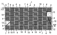
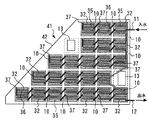
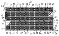
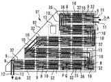
以下、図1乃至図9を参照して、本発明の実施の形態1について説明する。なお、本明細書で使用する各図においては、共通する要素に同一の符号を付し、重複する説明を省略するものとする。図1は、本発明の実施の形態1による太陽光熱ハイブリッドパネルを表面側からみた構成図を示し、図2は、この太陽光熱ハイブリッドパネルを裏面側からみた構成図を示している。これらの図に示すように、本実施の形態による太陽光熱ハイブリッドパネル1は、太陽光発電パネル2、太陽電池セル3、太陽熱収集器4、連通管10、接続端子13等を備えている。なお、図2では、太陽熱収集器4の内部に設けられた熱媒体流路7を透視状態で示している。本明細書では、実施の形態2以降で用いる図面においても、必要に応じて太陽熱収集器を透視状態で示している。
Embodiment 1 FIG.
Hereinafter, Embodiment 1 of the present invention will be described with reference to FIGS. In each drawing used in this specification, common elements are denoted by the same reference numerals, and redundant description is omitted. FIG. 1 shows a configuration diagram of a solar thermal hybrid panel according to Embodiment 1 of the present invention as viewed from the front surface side, and FIG. 2 shows a configuration diagram of this solar thermal hybrid panel as viewed from the back surface side. As shown in these drawings, the solar thermal hybrid panel 1 according to the present embodiment includes a photovoltaic power generation panel 2, a solar battery cell 3, a solar thermal collector 4, a communication pipe 10, a connection terminal 13, and the like. In FIG. 2, the heat medium flow path 7 provided inside the solar heat collector 4 is shown in a transparent state. In the present specification, the solar heat collector is shown in a transparent state in the drawings used in the second and subsequent embodiments as necessary.

太陽光発電パネル2は、例えば絶縁性を有する樹脂材料により四角形の板状(シート状)に形成されている。太陽光発電パネル2の表面側には、図1に示すように、太陽光を受けて発電する複数個の太陽電池セル3が設けられている。これらの太陽電池セル3は、例えば互いに大きさが等しい四角形状のセルとして形成され、太陽光発電パネル2の四辺のうち互いに直交する二辺に沿って格子状に並べて配置されている。言い換えると、太陽電池セル3は、太陽光発電パネル2の長さ方向及び幅方向(図1の左右方向及び上下方向)に沿ってそれぞれ2個以上並べられている。   The photovoltaic power generation panel 2 is formed in a rectangular plate shape (sheet shape) by using, for example, an insulating resin material. On the surface side of the photovoltaic power generation panel 2, as shown in FIG. 1, a plurality of solar cells 3 that generate power by receiving sunlight are provided. These solar cells 3 are formed, for example, as quadrangular cells having the same size, and are arranged in a lattice pattern along two sides orthogonal to each other among the four sides of the photovoltaic power generation panel 2. In other words, two or more solar cells 3 are arranged along the length direction and the width direction of the photovoltaic power generation panel 2 (left-right direction and up-down direction in FIG. 1).

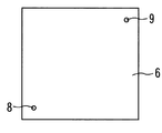
太陽熱収集器4は、日照により温度が上昇する太陽光発電パネル2の熱を熱交換により収集するもので、図2に示すように、太陽光発電パネル2の裏面側には、複数個の太陽熱収集器4が密着した状態で格子状に並べて配置されている。個々の太陽熱収集器4は、互いに等しい外形状を有する同一の部品により構成され、図3乃至図5に示すような構造を有している。ここで、図3は、本発明の実施の形態1において、太陽熱収集器を太陽光発電パネルの表面と垂直な方向に破断した状態を示す縦断面図である。また、図4は、太陽熱収集器を図3中の矢示A−A方向に沿って破断した状態を示す横断面図である。図5は、太陽熱収集器の蓋板を図3中の矢示A−A方向からみた単体図である。なお、図3乃至図5では、太陽熱収集器4のみを図示し、連通管10等の図示は省略している。   The solar heat collector 4 collects heat of the photovoltaic power generation panel 2 whose temperature rises due to sunshine by heat exchange. As shown in FIG. The collectors 4 are arranged side by side in a grid pattern in a close contact state. Each of the solar heat collectors 4 is composed of the same parts having the same outer shape, and has a structure as shown in FIGS. Here, FIG. 3 is a longitudinal sectional view showing a state in which the solar heat collector is broken in the direction perpendicular to the surface of the photovoltaic power generation panel in the first embodiment of the present invention. 4 is a cross-sectional view showing a state in which the solar heat collector is broken along the direction indicated by arrows AA in FIG. FIG. 5 is a single view of the cover plate of the solar heat collector as viewed from the direction indicated by arrows AA in FIG. 3 to 5, only the solar heat collector 4 is shown, and the communication pipe 10 and the like are not shown.

太陽熱収集器4は、全体として扁平な四角形の箱形状に形成されており、収集器本体5と蓋板6とを備えている。収集器本体5は、図3及び図4に示すように、両側が開口した四角形の枠状をなす枠状部5Aと、枠状部5Aの片側を閉塞する閉塞板部5Bと、枠状部5Aの内側で閉塞板部5Bから突出する複数のリブ5Cとを備えている。これらの枠状部5A、閉塞板部5B及び各リブ5Cは、高い熱伝導性を有する材料(例えば金属材料、または、熱伝導性が比較的良好な樹脂材料等)により一体成形してもよい。   The solar heat collector 4 is formed in a flat rectangular box shape as a whole, and includes a collector main body 5 and a cover plate 6. As shown in FIGS. 3 and 4, the collector main body 5 includes a frame-shaped portion 5A having a quadrangular frame shape that is open on both sides, a blocking plate portion 5B that closes one side of the frame-shaped portion 5A, and a frame-shaped portion. A plurality of ribs 5C projecting from the closing plate portion 5B inside 5A. The frame-like portion 5A, the blocking plate portion 5B, and the ribs 5C may be integrally formed of a material having high thermal conductivity (for example, a metal material or a resin material having relatively good thermal conductivity). .

蓋板6は、例えば接着等の手段を用いて収集器本体5の開口部に取付けられ、枠状部5Aを閉塞板部5Bと反対側から閉塞している。この状態で、各リブ5Cは、蓋板6と閉塞板部5Bとの間に形成される空間を仕切るように配置され、この空間内にクランク状に屈曲して延びた熱媒体流路7を形成している。熱媒体流路7には、太陽光発電パネル2から熱を回収するための熱回収媒体が流通される。熱回収媒体としては、例えば水、プロピレングリコール等のブラインが用いられる。   The lid plate 6 is attached to the opening of the collector main body 5 by means of, for example, adhesion, and closes the frame-like portion 5A from the side opposite to the closing plate portion 5B. In this state, each rib 5C is arranged so as to partition a space formed between the lid plate 6 and the closing plate portion 5B, and the heat medium flow path 7 bent and extended in a crank shape in this space. Forming. A heat recovery medium for recovering heat from the photovoltaic power generation panel 2 is circulated in the heat medium flow path 7. As the heat recovery medium, for example, brine such as water or propylene glycol is used.

また、蓋板6には、図3乃至図5に示すように、熱媒体流路7の両端部のうち一方の端部に開口する熱媒体流入口8と、熱媒体流路7の他方の端部に開口する熱媒体流出口9とが設けられている。熱媒体流入口8と熱媒体流出口9とは、熱媒体流路7に熱回収媒体を流通させるための熱媒体出入口を構成している。   3 to 5, the cover plate 6 has a heat medium inlet 8 that opens at one end of both ends of the heat medium flow path 7 and the other of the heat medium flow path 7. A heat medium outlet 9 opening at the end is provided. The heat medium inlet 8 and the heat medium outlet 9 constitute a heat medium inlet / outlet for allowing the heat recovery medium to flow through the heat medium flow path 7.

なお、太陽熱収集器4のうち太陽光発電パネル2の裏面側と密着する閉塞板部5Bには、熱伝導性が高い材料を用いるのが好ましく、更に、閉塞板部5Bの肉厚は、熱伝導性を高めるために出来るだけ薄くするのが好ましい。また、太陽熱収集器4のうち閉塞板部5B以外の部位には、軽量な材料を用いるのが好ましい。さらに、蓋板6と垂直な方向における太陽熱収集器4の厚さ寸法は、軽量化を図るために出来るだけ薄くするのが好ましい。   In addition, it is preferable to use a material having high thermal conductivity for the closing plate portion 5B that is in close contact with the back surface side of the photovoltaic power generation panel 2 in the solar heat collector 4, and the thickness of the closing plate portion 5B is the heat It is preferable to make it as thin as possible in order to increase conductivity. Moreover, it is preferable to use a lightweight material for parts other than the blocking plate portion 5B in the solar heat collector 4. Further, the thickness dimension of the solar heat collector 4 in the direction perpendicular to the cover plate 6 is preferably as thin as possible in order to reduce the weight.

このように構成された太陽熱収集器4は、図2に示すように、太陽光発電パネル2の裏面の面積範囲内に収まるように当該裏面側に格子状(マトリクス状)に並べて配置され、太陽光発電パネル2の長さ方向及び幅方向に沿ってそれぞれ2個以上並べられている。この状態で、各太陽熱収集器4の収集器本体5の閉塞板部5Bと太陽光発電パネル2の裏面とは、例えば熱伝導率が高くて柔らかな熱伝導シート、ゴムシート等のシート材料、または、接着剤、ホットメルト等の材料を用いて密着(面接触)した状態で固定されている。   As shown in FIG. 2, the solar heat collector 4 configured as described above is arranged in a grid (matrix shape) on the back surface side so as to be within the area of the back surface of the photovoltaic power generation panel 2. Two or more pieces are arranged along the length direction and the width direction of the photovoltaic panel 2. In this state, the closing plate portion 5B of the collector body 5 of each solar heat collector 4 and the back surface of the photovoltaic power generation panel 2 are, for example, a sheet material such as a heat conductive sheet having a high thermal conductivity and soft, a rubber sheet, Alternatively, they are fixed in close contact (surface contact) with a material such as an adhesive or hot melt.

また、太陽光発電パネル2の裏面上における太陽熱収集器4の面積は、太陽電池セル3の面積以下に形成されている。より具体的な構成例を述べると、四角形状をなす太陽熱収集器4の大きさ(縦寸法及び横寸法)は、太陽電池セル3の四辺の縦寸法及び横寸法以下の寸法値に設定されている。この構成によれば、個々の太陽熱収集器4の重量を小さくすることができ、太陽熱収集器4の重量による太陽光発電パネル2の反り、撓み等を抑制することができる。   Moreover, the area of the solar heat collector 4 on the back surface of the photovoltaic power generation panel 2 is formed to be equal to or less than the area of the solar battery cell 3. To describe a more specific configuration example, the size (vertical dimension and horizontal dimension) of the solar heat collector 4 having a quadrangular shape is set to a dimension value equal to or smaller than the vertical dimension and horizontal dimension of the four sides of the solar battery cell 3. Yes. According to this configuration, it is possible to reduce the weight of each solar heat collector 4 and to suppress warping, bending, and the like of the solar power generation panel 2 due to the weight of the solar heat collector 4.

また、1個の太陽熱収集器4が太陽光発電パネル2に接着される面積を小さくすることができるので、太陽熱収集器4の熱膨張及び熱収縮により接着面の剥離、割れ等が生じるのを抑制し、太陽熱収集器4の接着状態を安定させることができる。しかも、太陽熱収集器4を小型化することにより、その製造時に閉塞板部5B及び蓋板6の平面度を容易に向上させることができる。これにより、太陽熱収集器4と太陽光発電パネル2との密着性を高めることができる。さらに、例えば1個の太陽電池セル3の裏面側に1個の太陽熱収集器4を配置することができるので、各太陽電池セル3を効率よく、かつ、均等に冷却することができ、太陽光発電パネル2の発電効率を向上させることができる。   In addition, since the area where one solar heat collector 4 is bonded to the photovoltaic power generation panel 2 can be reduced, peeling or cracking of the bonding surface is caused by the thermal expansion and contraction of the solar heat collector 4. It can suppress and can stabilize the adhesion state of solar collector 4. In addition, by reducing the size of the solar heat collector 4, the flatness of the closing plate portion 5B and the cover plate 6 can be easily improved during manufacture. Thereby, the adhesiveness of the solar-heat collector 4 and the photovoltaic power generation panel 2 can be improved. Furthermore, for example, since one solar heat collector 4 can be arranged on the back side of one solar cell 3, each solar cell 3 can be efficiently and evenly cooled, The power generation efficiency of the power generation panel 2 can be improved.

また、互いに隣接する太陽熱収集器4の間には、両者間の熱伝導を抑制するのに必要な寸法をもつ断熱構造としての隙間が設けられている。この構成によれば、太陽電池セル3と太陽熱収集器4との間のみで熱交換を行うことができる。即ち、太陽電池セル3から太陽熱収集器4に吸収された熱が隣接する太陽熱収集器4に伝導するのを抑制し、太陽熱収集器4間の熱伝導により太陽電池セル3の冷却効率が低下するのを防止することができる。なお、上記説明では、断熱構造の一例として隙間を例示したが、本発明はこれに限らず、例えば断熱材等を含む各種の断熱構造を各太陽熱収集器4の間に設けてもよい。また、太陽光発電パネル2上の各太陽電池セル3は、互いに接触しないように数ミリ程度の間隔をもって離間している。従って、発電量の増加に寄与する太陽電池セル3においては、これと密着した太陽熱収集器4により当該太陽電池セル3のみを効率的に冷却し、発電量を増加させることができる。   Further, a gap as a heat insulating structure having a dimension necessary for suppressing heat conduction between the solar collectors 4 adjacent to each other is provided. According to this configuration, heat exchange can be performed only between the solar battery cell 3 and the solar heat collector 4. That is, the heat absorbed by the solar heat collector 4 from the solar battery cell 3 is suppressed from being conducted to the adjacent solar heat collector 4, and the cooling efficiency of the solar battery cell 3 is reduced by the heat conduction between the solar heat collectors 4. Can be prevented. In the above description, the gap is illustrated as an example of the heat insulating structure. However, the present invention is not limited thereto, and various heat insulating structures including a heat insulating material or the like may be provided between the solar heat collectors 4. In addition, the solar cells 3 on the photovoltaic power generation panel 2 are spaced apart by a few millimeters so as not to contact each other. Therefore, in the solar cell 3 that contributes to an increase in the amount of power generation, only the solar cell 3 can be efficiently cooled by the solar heat collector 4 in close contact therewith, and the amount of power generation can be increased.

また、互いに異なる太陽熱収集器4の熱媒体流入口8と熱媒体流出口9とは、それぞれ連通管10を介して連通されている。これら複数の連通管10は、太陽光発電パネル2に設けられた各太陽熱収集器4の熱媒体流路7が全体として1つの熱媒体流通経路を構成するように、熱媒体流入口8と熱媒体流出口9とを連通している。そして、全体の熱媒体流通経路の最上流部となる熱媒体流入口8には、太陽光熱ハイブリッドパネル1の外部から各太陽熱収集器4の熱媒体流路7に熱回収媒体を導入する熱媒体導入通路としての熱媒体導入管11が設けられている。また、前記全体の熱媒体流通経路の最下流部となる熱媒体流出口9には、各太陽熱収集器4の熱媒体流路7を流通した熱回収媒体を太陽光熱ハイブリッドパネル1の外部に導出する熱媒体導出通路としての熱媒体導出管12が設けられている。   Further, the heat medium inlet 8 and the heat medium outlet 9 of the different solar heat collectors 4 are communicated with each other via a communication pipe 10. The plurality of communication pipes 10 are connected to the heat medium inlet 8 and the heat medium so that the heat medium flow path 7 of each solar heat collector 4 provided in the solar power generation panel 2 constitutes one heat medium flow path as a whole. The medium outlet 9 communicates with the medium outlet 9. A heat medium that introduces a heat recovery medium from the outside of the solar heat hybrid panel 1 to the heat medium flow path 7 of each solar heat collector 4 is input to the heat medium inlet 8 that is the most upstream part of the entire heat medium flow path. A heat medium introduction pipe 11 is provided as an introduction passage. Further, the heat recovery medium flowing through the heat medium flow path 7 of each solar heat collector 4 is led out of the solar heat hybrid panel 1 to the heat medium outlet 9 which is the most downstream part of the entire heat medium distribution path. A heat medium outlet tube 12 is provided as a heat medium outlet passage.

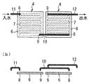
図6及び図7は、本発明の実施の形態1において、太陽熱収集器と連通管等との接続構造の例を示す構成図である。なお、図6(a)及び図7(a)は、太陽熱収集器4等を太陽光発電パネル2の裏面側からみた構成図を示し、図6(b)及び図7(b)は、図6(a)及び図7(a)中の蓋板6、連通管10等を分解した状態で側方からみた構成図を示している。連通管10の端部は、例えば接着等の手段を用いて太陽熱収集器4の熱媒体流入口8と熱媒体流出口9にそれぞれ接続されている。なお、両者の接続部は、ねじ加工等を施すことにより螺着して接続したり、例えばホースニップル等の配管接続器を介して接続する構成としてもよい。また、熱媒体導入管11及び熱媒体導出管12は、連通管10と同様の方法により熱媒体流入口8及び熱媒体流出口9に接続されている。   6 and 7 are configuration diagrams showing an example of a connection structure between the solar heat collector and the communication pipe in the first embodiment of the present invention. 6 (a) and 7 (a) show the configuration of the solar heat collector 4 and the like viewed from the back side of the photovoltaic power generation panel 2, and FIGS. 6 (b) and 7 (b) are diagrams. The block diagram which looked from the side in the state which decomposed | disassembled the cover plate 6, the communication pipe | tube 10, etc. in 6 (a) and FIG. 7 (a) is shown. The ends of the communication pipe 10 are connected to the heat medium inlet 8 and the heat medium outlet 9 of the solar heat collector 4 using means such as adhesion. Note that the connecting portions of the two may be connected by screwing or the like, or may be connected via a pipe connector such as a hose nipple. Further, the heat medium introduction pipe 11 and the heat medium outlet pipe 12 are connected to the heat medium inlet 8 and the heat medium outlet 9 in the same manner as the communication pipe 10.

一方、太陽光熱ハイブリッドパネル1は、複数個の太陽光発電パネル2を連結した状態で使用されることが多いので、個々の太陽光発電パネル2には、隣接した太陽光発電パネル2同士を電気的に接続するボックス状の接続端子13が設けられている。なお、製品の仕様等により接続端子13の適切な位置が異なる場合には、太陽熱収集器4及び連通管10の配置を適宜変更してもよい。また、太陽光発電パネル2の裏面側には、必ずしも太陽熱収集器4を全面にわたって配置する必要はなく、接続端子13の位置以外にも太陽熱収集器4が配置されていない部位が存在してもよい。   On the other hand, since the solar thermal hybrid panel 1 is often used in a state in which a plurality of photovoltaic power generation panels 2 are connected to each other, the individual photovoltaic power generation panels 2 are electrically connected to each other. A box-shaped connection terminal 13 is provided for connection. In addition, when the appropriate position of the connection terminal 13 changes with the specifications of a product, etc., you may change suitably arrangement | positioning of the solar-heat collector 4 and the communicating pipe 10. FIG. Moreover, it is not always necessary to arrange the solar heat collector 4 over the entire rear surface side of the photovoltaic power generation panel 2, even if there is a part where the solar heat collector 4 is not arranged other than the position of the connection terminal 13. Good.

本実施の形態による太陽光熱ハイブリッドパネル1は上述の如き構成を有するもので、次に、その作動について説明する。まず、太陽光熱ハイブリッドパネル1は、太陽光発電及び太陽熱の回収を行うソーラーシステムの一部を構成しており、家屋の屋根等に設置される。そして、太陽光熱ハイブリッドパネル1の熱媒体導入管11及び熱媒体導出管12には、ソーラーシステムの熱媒体循環装置が接続される。熱媒体循環装置は、ポンプ等を用いて太陽光熱ハイブリッドパネル1の各熱媒体流路7(熱媒体流通経路)に熱回収媒体を循環させるものである。   The solar thermal hybrid panel 1 according to the present embodiment has the above-described configuration, and the operation thereof will be described next. First, the solar thermal hybrid panel 1 constitutes a part of a solar system that performs solar power generation and solar heat recovery, and is installed on the roof of a house. Then, the heat medium circulation device of the solar system is connected to the heat medium introduction tube 11 and the heat medium outlet tube 12 of the solar heat hybrid panel 1. The heat medium circulation device circulates the heat recovery medium in each heat medium flow path 7 (heat medium flow path) of the solar heat hybrid panel 1 using a pump or the like.

太陽光発電パネル2の表面側に太陽光が照射されると、各太陽電池セル3により太陽光発電が実行され、発電された電力は接続端子13を経由して家屋の分電盤等に供給される。このとき、日照等により温度が上昇した太陽電池セル3の熱は、各太陽熱収集器4の熱媒体流路7を流れる熱回収媒体により吸収され、太陽電池セル3は冷却される。熱回収媒体は、熱媒体導入管11から1個の太陽熱収集器4の熱媒体流路7に流入し、各連通管10を経由して全ての太陽熱収集器4の熱媒体流路7を流通した後に、熱媒体導出管12から流出し、熱媒体循環装置に戻される。これにより、熱媒体循環装置は、熱回収媒体を用いて太陽光発電パネル2から熱を回収し、回収された熱は給湯等に利用される。   When sunlight is irradiated on the surface side of the photovoltaic power generation panel 2, photovoltaic power generation is performed by each solar battery cell 3, and the generated power is supplied to a distribution board or the like of the house via the connection terminals 13. Is done. At this time, the heat of the solar cells 3 whose temperature has increased due to sunshine or the like is absorbed by the heat recovery medium flowing through the heat medium flow path 7 of each solar heat collector 4, and the solar cells 3 are cooled. The heat recovery medium flows from the heat medium introduction pipe 11 into the heat medium flow path 7 of one solar heat collector 4, and flows through the heat medium flow paths 7 of all the solar heat collectors 4 through the respective communication pipes 10. After that, it flows out from the heat medium outlet pipe 12 and is returned to the heat medium circulation device. Thus, the heat medium circulation device recovers heat from the solar power generation panel 2 using the heat recovery medium, and the recovered heat is used for hot water supply or the like.

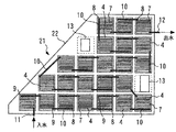
一方、本実施の形態では、図8に示すように、太陽熱収集器4の並べ方、並べる個数等を変更することにより、他の太陽光熱ハイブリッドパネル21を容易に構成することができる。図8は、本発明の実施の形態1において、規格外の形状または寸法をもつ他の太陽光熱ハイブリッドパネル21を構成した場合を示す構成図である。この図は、太陽光発電パネル22を裏面側からみた状態を示している。図8に示す構成例において、太陽光発電パネル22は、例えば太陽光熱ハイブリッドパネル21の設置場所の形状等に対応して台形状に形成されている。そして、太陽光発電パネル22の裏面側には、複数個の太陽熱収集器4が互いに直交する2方向に沿ってそれぞれ2個以上並べて配置され、全体として略台形状となるように格子状に並べて配置されている。   On the other hand, in this Embodiment, as shown in FIG. 8, the other solar thermal hybrid panel 21 can be easily comprised by changing the arrangement method, the number of arrangement | sequences, etc. of the solar-heat collector 4. As shown in FIG. FIG. 8 is a configuration diagram showing a case where another solar thermal hybrid panel 21 having a nonstandard shape or size is configured in the first embodiment of the present invention. This figure has shown the state which looked at the photovoltaic power generation panel 22 from the back surface side. In the configuration example shown in FIG. 8, the solar power generation panel 22 is formed in a trapezoidal shape corresponding to the shape of the installation location of the solar thermal hybrid panel 21, for example. And on the back surface side of the photovoltaic power generation panel 22, a plurality of solar heat collectors 4 are arranged side by side along two directions orthogonal to each other, and arranged in a lattice shape so as to be substantially trapezoidal as a whole. Has been placed.

以上詳述した通り、本実施の形態によれば、太陽電池セル3以下の大きさに形成した複数個の太陽熱収集器4を、太陽光発電パネル2の裏面側に並べて配置する構成としている。これにより、例えば図2及び図8に示すように、形状または寸法が異なる複数種類の太陽光発電パネル2,22が存在する場合でも、太陽熱収集器4の並べ方及び並べる個数等を変更することにより、太陽光発電パネル2,22の裏面側を太陽熱収集器4によって覆うことができる。   As described above in detail, according to the present embodiment, a plurality of solar heat collectors 4 having a size smaller than that of the solar battery cell 3 are arranged side by side on the back surface side of the photovoltaic power generation panel 2. Thus, for example, as shown in FIGS. 2 and 8, even when there are a plurality of types of photovoltaic power generation panels 2 and 22 having different shapes or dimensions, by changing the arrangement and the number of the solar heat collectors 4 arranged, etc. The back surface side of the photovoltaic power generation panels 2 and 22 can be covered by the solar heat collector 4.

従って、同一の外形状を有する1種類の太陽熱収集器4を共通な部品として、複数種類の太陽光熱ハイブリッドパネル1,21を組立てることができる。即ち、種類が異なる太陽光発電パネルに対応して、複数種類の太陽熱収集器4を個別に設計及び製造する必要がないので、太陽光熱ハイブリッドパネルの製品ラインナップ全体において、太陽熱収集器4等の部品点数を削減することができ、製造効率を高めて製造コストを抑制することができる。また、屋根の設置スペース等に対して、太陽光熱ハイブリッドパネル1,21の形状及び寸法を容易に合わせることができるので、太陽光熱ハイブリッドパネル1,21の設置自由度が高いソーラーシステムを実現することができる。   Accordingly, a plurality of types of solar thermal hybrid panels 1 and 21 can be assembled using one type of solar heat collector 4 having the same outer shape as a common component. That is, it is not necessary to individually design and manufacture a plurality of types of solar heat collectors 4 corresponding to different types of solar power generation panels, and therefore, components such as solar heat collectors 4 in the entire solar heat hybrid panel product lineup. The number of points can be reduced, manufacturing efficiency can be increased, and manufacturing cost can be suppressed. Moreover, since the shape and dimensions of the solar thermal hybrid panels 1 and 21 can be easily matched to the installation space of the roof, etc., a solar system with a high degree of freedom of installation of the solar thermal hybrid panels 1 and 21 should be realized. Can do.

また、四角形のパネル状に形成した太陽熱収集器4を格子状に並べて連結するので、従来技術のように一方向にのみ細長く延びた集熱部材を用いる場合と比較して、太陽光発電パネル2に生じる反り、撓み等の変形を抑制することができる。これにより、太陽光発電パネル2と太陽熱収集器4との間の密着度及び熱伝導性を高めることができ、各太陽熱収集器4により太陽電池セル3を効率よく冷却することができる。この結果、太陽電池セル3の温度上昇を抑制し、発電効率を向上させることができる。なお、太陽電池セル3は、同一の日射量に対してセルの温度が低いほど発電効率が向上する特性を有しているので、この特性に基いて太陽電池セル3の発電効率及び発電量を向上させることができる。   Further, since the solar heat collectors 4 formed in a square panel shape are arranged and connected in a grid pattern, the photovoltaic power generation panel 2 is compared with the case of using a heat collecting member elongated in only one direction as in the prior art. It is possible to suppress deformation such as warping and bending. Thereby, the adhesion degree and thermal conductivity between the solar power generation panel 2 and the solar heat collector 4 can be increased, and the solar cells 3 can be efficiently cooled by the solar heat collectors 4. As a result, the temperature rise of the solar battery cell 3 can be suppressed and the power generation efficiency can be improved. In addition, since the photovoltaic cell 3 has the characteristic that power generation efficiency improves, so that the temperature of a cell is low with respect to the same amount of solar radiation, the power generation efficiency and power generation amount of the photovoltaic cell 3 are based on this characteristic. Can be improved.

また、太陽光発電パネル2の裏面側には、複数個の太陽光発電パネル2同士を電気的に接続する接続端子13が設けられている。接続端子13はボックス状の突起物であり、パネル同士の接続に適した位置に取付ける必要がある。これに対し、本実施の形態では、太陽熱収集器4の配置を自由に設定することができる。従って、特別な加工等を施さなくても、接続端子13の配置スペースを確保しつつ、他の位置で太陽光発電パネル2の裏面側を覆うように太陽熱収集器4を容易に並べることができる。   Further, on the back side of the photovoltaic power generation panel 2, a connection terminal 13 that electrically connects the plurality of photovoltaic power generation panels 2 is provided. The connection terminal 13 is a box-shaped protrusion and needs to be attached at a position suitable for connection between panels. On the other hand, in this Embodiment, arrangement | positioning of the solar-heat collector 4 can be set freely. Accordingly, the solar heat collector 4 can be easily arranged so as to cover the back surface side of the photovoltaic power generation panel 2 at another position while securing the arrangement space of the connection terminals 13 without performing special processing or the like. .

また、太陽熱収集器4を小型化することにより、太陽光発電パネル2の裏面に沿って延びる熱媒体流路7の総流路面積を増加させることができる。これにより、太陽熱収集器4の冷却性能を向上させ、太陽電池セル3の発電効率を高めることができる。しかも、小型の太陽熱収集器4を用いることにより、例えば熱媒体流路7の高さ寸法(即ち、閉塞板部5Bと蓋板6との離間寸法)を小さく形成し、熱媒体流路7の断面積を容易に減少させることができる。これにより、熱媒体流路7を流れる熱回収媒体の流速を増加させ、その熱伝達性能を高めることができ、太陽熱収集器4の冷却能力を向上させることができる。   Further, by reducing the size of the solar heat collector 4, the total flow path area of the heat medium flow path 7 extending along the back surface of the photovoltaic power generation panel 2 can be increased. Thereby, the cooling performance of the solar-heat collector 4 can be improved and the electric power generation efficiency of the photovoltaic cell 3 can be improved. In addition, by using the small solar heat collector 4, for example, the height dimension of the heat medium flow path 7 (that is, the separation dimension between the closing plate portion 5 </ b> B and the cover plate 6) is reduced, and the heat medium flow path 7. The cross-sectional area can be easily reduced. Thereby, the flow rate of the heat recovery medium flowing through the heat medium flow path 7 can be increased, the heat transfer performance can be improved, and the cooling capacity of the solar heat collector 4 can be improved.

なお、実施の形態1では、太陽熱収集器4の収集器本体5の閉塞板部5Bを太陽光発電パネル2の裏面側に密着させる構成とした。しかし、本発明はこれに限らず、例えば図9に示すように構成してもよい。図9は、本発明の実施の形態1における変形例を示す図3と同様の縦断面図である。この変形例の太陽光熱ハイブリッドパネル1′においては、太陽熱収集器4′の熱媒体流入口8及び熱媒体流出口9が収集器本体5の閉塞板部5Bに形成されており、蓋板6は、穴が存在しない平板として形成されている。そして、太陽熱収集器4′は、蓋板6が太陽光発電パネル2の裏面側に密着した状態で、太陽光発電パネル2に取付けられている。   In the first embodiment, the closing plate portion 5B of the collector main body 5 of the solar heat collector 4 is in close contact with the back surface side of the photovoltaic power generation panel 2. However, the present invention is not limited to this, and may be configured as shown in FIG. 9, for example. FIG. 9 is a longitudinal sectional view similar to FIG. 3, showing a modification of the first embodiment of the present invention. In the solar heat hybrid panel 1 ′ of this modification, the heat medium inlet 8 and the heat medium outlet 9 of the solar heat collector 4 ′ are formed in the closing plate portion 5 </ b> B of the collector body 5, and the cover plate 6 is , Formed as a flat plate without holes. The solar heat collector 4 ′ is attached to the solar power generation panel 2 with the cover plate 6 in close contact with the back side of the solar power generation panel 2.

上記変形例によれば、太陽熱収集器4のうち平面度が高く、かつ、薄肉な部位である蓋板6を太陽光発電パネル2の裏面側に密着させることができる。即ち、収集器本体5は、例えば切削加工、金型等を用いた加工等により形成するので、加工成型時に反りが生じたり、閉塞板部5Bの平面度が低下することがあり、また、薄肉化するにも限界がある。これに対し、蓋板6は、平坦な薄板として正確に形成し易いので、太陽光発電パネル2に対する密着度及び熱伝導性を高めることができる。   According to the above modification, the cover plate 6, which has a high flatness and is a thin part, in the solar heat collector 4 can be brought into close contact with the back surface side of the photovoltaic power generation panel 2. That is, since the collector body 5 is formed by, for example, cutting or processing using a mold, warping may occur during processing molding, or the flatness of the closing plate portion 5B may be reduced. There is a limit to the conversion. On the other hand, since the cover plate 6 is easy to be accurately formed as a flat thin plate, it is possible to improve the adhesion and thermal conductivity to the photovoltaic power generation panel 2.

実施の形態2.
次に、図10乃至図15を参照して、本発明の実施の形態2について説明する。本実施の形態は、1個の太陽熱収集器に複数個の熱媒体流路を設けたことを特徴としている。図10は、本発明の実施の形態2による太陽光熱ハイブリッドパネルを裏面側からみた構成図である。本実施の形態の太陽光熱ハイブリッドパネル31は、前記実施の形態1とほぼ同様に、太陽光発電パネル2、太陽電池セル3、連通管10、熱媒体導入管11、熱媒体導出管12、接続端子13等を備えている。また、太陽光発電パネル2の裏面側には、太陽電池セル3以下の大きさに形成された複数個の太陽熱収集器32が格子状に並べて配置されているものの、各太陽熱収集器32は、図11乃至図13に示す構成を有している。
Embodiment 2. FIG.
Next, a second embodiment of the present invention will be described with reference to FIGS. This embodiment is characterized in that a plurality of heat medium flow paths are provided in one solar heat collector. FIG. 10 is a configuration diagram of the solar thermal hybrid panel according to the second embodiment of the present invention as viewed from the back side. The solar heat hybrid panel 31 of the present embodiment is similar to the first embodiment in that the solar power generation panel 2, the solar battery cell 3, the communication pipe 10, the heat medium introduction pipe 11, the heat medium outlet pipe 12, and the connection Terminal 13 etc. are provided. Moreover, although the several solar heat collector 32 formed in the magnitude | size below the photovoltaic cell 3 is arranged in the grid | lattice form on the back surface side of the photovoltaic power generation panel 2, each solar heat collector 32 is as follows. The configuration shown in FIGS. 11 to 13 is provided.

図11は、本発明の実施の形態2による太陽熱収集器を図3と同様位置からみた縦断面図である。図12は、太陽熱収集器を図11中の矢示A−A方向に沿って破断した状態を示す横断面図である。図13は、本発明の実施の形態2において、太陽熱収集器と連通管等との接続構造の一例を示す構成図である。また、図13(a)は、太陽熱収集器32等を太陽光発電パネル2の裏面側からみた構成図を示し、図13(b)は、図13(a)中の蓋板34、連通管10等を分解した状態で側方からみた構成図を示している。   FIG. 11 is a longitudinal sectional view of the solar heat collector according to the second embodiment of the present invention as seen from the same position as in FIG. FIG. 12 is a cross-sectional view showing a state in which the solar heat collector is broken along the direction of arrows AA in FIG. FIG. 13 is a configuration diagram illustrating an example of a connection structure between a solar heat collector and a communication pipe in the second embodiment of the present invention. Moreover, Fig.13 (a) shows the block diagram which looked at the solar heat collector 32 grade | etc., From the back surface side of the photovoltaic power generation panel 2, FIG.13 (b) shows the cover plate 34 in FIG.13 (a), a communicating pipe | tube. The block diagram seen from the side in the state which decomposed | disassembled 10 grade | etc., Is shown.

太陽熱収集器32は、実施の形態1とほぼ同様に、全体として扁平な四角形の箱形状に形成されており、枠状部33A、閉塞板部33B及び複数のリブ33Cを有する収集器本体33と、収集器本体33の開口部を閉塞する蓋板34とを備えている。収集器本体33と蓋板34との間には、各リブ33Cにより例えば2つの熱媒体流路35,36が形成され、これらの熱媒体流路35,36は、図12に示すように、それぞれクランク状に屈曲して延びている。収集器本体33の内部には、熱媒体流路35,36の間を仕切る隔壁33Dが設けられている。また、蓋板34には、熱媒体流路35,36の両端部にそれぞれ開口する4個の熱媒体出入口37が形成されている。各熱媒体流路35,36にそれぞれ設けられた2個の熱媒体出入口37は、一方が熱媒体流入口となり、他方が熱媒体流出口となるものである。   The solar heat collector 32 is formed in a flat rectangular box shape as a whole in substantially the same manner as in the first embodiment, and includes a collector main body 33 having a frame-shaped portion 33A, a blocking plate portion 33B, and a plurality of ribs 33C. And a lid plate 34 that closes the opening of the collector main body 33. Between the collector body 33 and the lid plate 34, for example, two heat medium flow paths 35 and 36 are formed by the ribs 33C, and these heat medium flow paths 35 and 36, as shown in FIG. Each bends and extends in a crank shape. Inside the collector body 33, a partition wall 33 </ b> D that partitions the heat medium flow paths 35 and 36 is provided. Further, the cover plate 34 is formed with four heat medium inlets / outlets 37 that open at both ends of the heat medium flow paths 35, 36, respectively. One of the two heat medium inlets / outlets 37 provided in each of the heat medium flow paths 35 and 36 serves as a heat medium inlet and the other serves as a heat medium outlet.

そして、複数個の太陽熱収集器32を並べた状態では、熱媒体流路35,36のうち互いに異なる2つの熱媒体流路の熱媒体出入口37が連通管10を介して接続される。これにより、太陽光発電パネル2に設けられた各太陽熱収集器32の熱媒体流路35,36は、図13に示すように、全体として1つの熱媒体流通経路を構成している。なお、図13は、熱媒体流路35,36の接続を説明するために、2個の太陽熱収集器32を連結した場合を例示したもので、実際には、図10に示すように、3個以上の太陽熱収集器32が連結される。そして、全体の熱媒体流通経路の最上流部となる熱媒体出入口37には、熱媒体導入管11が接続され、全体の熱媒体流通経路の最下流部となる熱媒体出入口37には、熱媒体導出管12が接続されている。   In the state where the plurality of solar heat collectors 32 are arranged, the heat medium inlet / outlet 37 of two different heat medium flow paths among the heat medium flow paths 35 and 36 are connected via the communication pipe 10. Thereby, as shown in FIG. 13, the heat-medium flow paths 35 and 36 of each solar-heat collector 32 provided in the solar power generation panel 2 constitute one heat-medium distribution path as a whole. FIG. 13 illustrates a case where two solar collectors 32 are connected to explain the connection of the heat medium flow paths 35 and 36. In practice, as shown in FIG. One or more solar collectors 32 are connected. The heat medium inlet / outlet 37 is connected to the heat medium inlet / outlet 37 which is the uppermost stream portion of the entire heat medium circulation path, and the heat medium inlet / outlet 37 which is the most downstream portion of the entire heat medium circulation path is connected to the heat medium inlet / outlet 37. A medium outlet pipe 12 is connected.

このように構成される本実施の形態によれば、次のような効果を得ることができる。まず、小型の太陽熱収集器32を用いた場合には、太陽熱収集器32内の流路抵抗が増加したり、熱媒体流路35,36の断面積が小さくなることにより、熱媒体流路の圧力損失が増加し易い。また、熱回収媒体の流量を増やした場合にも、圧力損失が増加し易い。これに対し、本実施の形態では、個々の太陽熱収集器32内に設ける熱媒体流路を、必要に応じて2つ以上の熱媒体流路35,36に分割または分岐させることができる。これにより、例えば太陽熱収集器32の連結個数、熱回収媒体の流量等に応じて、太陽光熱ハイブリッドパネル31全体の熱媒体流通経路の流路抵抗(圧力損失)を適切に調整することができる。従って、太陽光発電パネル2の形状、寸法等に対応して太陽光熱ハイブリッドパネル31の構成を変更した場合でも、熱回収媒体を円滑に流通させることができる。   According to the present embodiment configured as described above, the following effects can be obtained. First, when the small solar heat collector 32 is used, the flow path resistance in the solar heat collector 32 is increased or the cross-sectional area of the heat medium flow paths 35 and 36 is reduced. Pressure loss tends to increase. Also, the pressure loss tends to increase when the flow rate of the heat recovery medium is increased. On the other hand, in this Embodiment, the heat-medium flow path provided in each solar collector 32 can be divided | segmented or branched into the 2 or more heat-medium flow paths 35 and 36 as needed. Thereby, for example, according to the number of connected solar heat collectors 32, the flow rate of the heat recovery medium, and the like, the flow path resistance (pressure loss) of the heat medium flow path of the entire solar heat hybrid panel 31 can be adjusted appropriately. Therefore, even when the configuration of the solar heat hybrid panel 31 is changed corresponding to the shape, size, etc. of the solar power generation panel 2, the heat recovery medium can be smoothly distributed.

また、本実施の形態によれば、例えば全体の熱媒体流通経路の流入部、流出部等において、当該熱媒体流路を複数の通路に分岐させることにより、流路抵抗を容易に減少させることができる。これにより、例えば熱回収媒体を熱媒体流路に循環させるポンプの吐出流量を一定とした前提においては、熱回収媒体の流量を増加させることができ、太陽熱収集器32の冷却性能を向上させることができる。また、熱回収媒体の流量を一定とした前提では、ポンプを小型化することができ、太陽光熱ハイブリッドパネル31の軽量化及び省エネルギ化を促進することができる。   Further, according to the present embodiment, for example, the flow path resistance can be easily reduced by branching the heat medium flow path into a plurality of passages in the inflow part, the outflow part, etc. of the entire heat medium flow path. Can do. Thereby, for example, on the assumption that the discharge flow rate of the pump that circulates the heat recovery medium to the heat medium flow path is constant, the flow rate of the heat recovery medium can be increased, and the cooling performance of the solar heat collector 32 can be improved. Can do. Moreover, on the premise that the flow rate of the heat recovery medium is constant, the pump can be downsized, and the solar heat hybrid panel 31 can be reduced in weight and energy saving.

また、本実施の形態でも、前記実施の形態1と同様に、四角形状の太陽光発電パネル2だけでなく、規格外の形状または寸法を有する各種の太陽光発電パネルにも太陽熱収集器32を適用することができる。図14は、本発明の実施の形態2において、規格外の形状または寸法をもつ他の太陽光熱ハイブリッドパネルを構成した場合を示す構成図である。この図において、太陽光熱ハイブリッドパネル41は、台形状の太陽光発電パネル42を備えており、太陽熱収集器32は、略台形状に並べられている。このように、本実施の形態によっても、前記実施の形態1と同様の効果を得ることができる。   Also in the present embodiment, as in the first embodiment, not only the rectangular photovoltaic power generation panel 2 but also the solar collectors 32 are applied to various photovoltaic power generation panels having non-standard shapes or dimensions. Can be applied. FIG. 14 is a configuration diagram illustrating a case where another solar thermal hybrid panel having a nonstandard shape or size is configured in the second embodiment of the present invention. In this figure, the solar thermal hybrid panel 41 includes a trapezoidal solar power generation panel 42, and the solar heat collectors 32 are arranged in a substantially trapezoidal shape. As described above, according to the present embodiment, the same effects as those of the first embodiment can be obtained.

また、本実施の形態では、例えば図15に示す変形例のように構成してもよい。この変形例の太陽光熱ハイブリッドパネル31′においては、太陽熱収集器32′の熱媒体出入口37が収集器本体33の閉塞板部33Bに形成されており、蓋板34は、穴が存在しない平板として形成されている。そして、太陽熱収集器32′は、蓋板34が太陽光発電パネル2の裏面側に密着した状態で、太陽光発電パネル2に取付けられている。この構成によれば、前記実施の形態1の変形例と同様の効果を得ることができる。   Moreover, in this Embodiment, you may comprise like the modification shown in FIG. 15, for example. In the solar heat hybrid panel 31 ′ of this modification, the heat medium inlet / outlet 37 of the solar heat collector 32 ′ is formed in the closing plate portion 33 </ b> B of the collector main body 33, and the lid plate 34 is a flat plate having no holes. Is formed. The solar heat collector 32 ′ is attached to the solar power generation panel 2 with the lid plate 34 being in close contact with the back side of the solar power generation panel 2. According to this configuration, the same effect as that of the modification of the first embodiment can be obtained.

また、本実施の形態では、1個の太陽熱収集器32に2個の熱媒体流路35,36を設ける場合を例示したが、本発明はこれに限らず、1個の太陽熱収集器に3個以上の熱媒体流路を設ける構成としてもよい。   Further, in the present embodiment, the case where the two heat medium flow paths 35 and 36 are provided in one solar heat collector 32 is illustrated, but the present invention is not limited thereto, and one solar heat collector 3 It is good also as a structure which provides one or more heat-medium flow paths.

実施の形態3.
次に、図16乃至図19を参照して、本発明の実施の形態3について説明する。本実施の形態は、1個の太陽熱収集器に互いに並列に接続された複数個の熱媒体流路を設けたことを特徴としている。図16は、本発明の実施の形態3による太陽熱収集器を図3と同様位置からみた縦断面図である。図17は、太陽熱収集器を図16中の矢示A−A方向に沿って破断した状態を示す横断面図である。図18は、太陽熱収集器の蓋板を図16中の矢示A−A方向からみた単体図である。
Embodiment 3 FIG.
Next, a third embodiment of the present invention will be described with reference to FIGS. The present embodiment is characterized in that a plurality of heat medium flow paths connected in parallel to each other are provided in one solar heat collector. FIG. 16 is a longitudinal sectional view of the solar heat collector according to the third embodiment of the present invention as viewed from the same position as in FIG. FIG. 17 is a cross-sectional view showing a state in which the solar heat collector is broken along the direction indicated by arrows AA in FIG. 18 is a single view of the cover plate of the solar heat collector as seen from the direction of arrows AA in FIG.

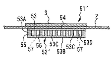
本実施の形態の太陽光熱ハイブリッドパネル51は、前記実施の形態1とほぼ同様に、太陽光発電パネル2、太陽電池セル3、連通管10等を備え、太陽光発電パネル2の裏面側には、太陽電池セル3以下の大きさに形成された複数個の太陽熱収集器52(1個のみ図示)が格子状に並べて配置されている。また、太陽熱収集器52は、実施の形態1とほぼ同様に、全体として扁平な四角形の箱形状に形成されており、枠状部53A、閉塞板部53B及び複数のリブ53Cを有する収集器本体53と、収集器本体53の開口部を閉塞する蓋板54とを備えている。   The solar thermal hybrid panel 51 of the present embodiment includes a photovoltaic power generation panel 2, solar cells 3, communication pipes 10, and the like, almost the same as in the first embodiment, and on the back side of the photovoltaic power generation panel 2. A plurality of solar heat collectors 52 (only one is shown) formed in the size of the solar battery cell 3 or less are arranged in a grid pattern. Further, the solar heat collector 52 is formed in a flat rectangular box shape as a whole in substantially the same manner as in the first embodiment, and has a collector main body having a frame-shaped portion 53A, a closing plate portion 53B, and a plurality of ribs 53C. 53 and a cover plate 54 that closes the opening of the collector main body 53.

収集器本体53と蓋板54との間には、各リブ53Cにより例えば2つの熱媒体流路55,56が形成されている。これらの熱媒体流路55,56は、図17に示すように、クランク状に屈曲しつつ、隔壁53Dを挟んで平行に延びている。隔壁53Dは、収集器本体53の内部に設けられ、クランク状に屈曲しつつ熱媒体流路55,56の間を仕切っている。また、隔壁53Dの両端部と枠状部53Aとの間には、それぞれ隙間53Eが設けられており、これらの隙間53Eは、2つの熱媒体流路55,56を長さ方向の両端側で互いに並列に接続している。   For example, two heat medium flow paths 55 and 56 are formed by the ribs 53 </ b> C between the collector main body 53 and the lid plate 54. As shown in FIG. 17, these heat medium flow paths 55 and 56 are bent in a crank shape and extend in parallel with the partition wall 53D interposed therebetween. The partition wall 53D is provided inside the collector main body 53 and partitions the heat medium flow paths 55 and 56 while bending in a crank shape. In addition, gaps 53E are provided between both end portions of the partition wall 53D and the frame-like portion 53A. These gaps 53E pass the two heat medium flow paths 55 and 56 at both end sides in the length direction. They are connected in parallel to each other.

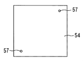
一方、蓋板54には、各隙間53Eの位置に開口する2個の熱媒体出入口57が設けられている。これらの熱媒体出入口57のうち一方は熱媒体流入口となり、他方は熱媒体流出口となるものである。そして、複数個の太陽熱収集器52を並べた状態では、熱媒体流路55,56のうち互いに異なる2つの熱媒体流路の熱媒体出入口57が連通管10を介して接続される。これにより、太陽光発電パネル2に設けられた各太陽熱収集器52の熱媒体流路55,56は、前記実施の形態2の場合とほぼ同様に、全体として1つの熱媒体流通経路を構成することができる。また、各熱媒体流路55,56は、後述のように、太陽光発電パネル2の裏面側に複数系統の熱媒体流通経路を構成することもできる。   On the other hand, the cover plate 54 is provided with two heat medium inlets / outlets 57 that open to the positions of the gaps 53E. One of the heat medium inlets and outlets 57 serves as a heat medium inlet and the other serves as a heat medium outlet. In the state where the plurality of solar heat collectors 52 are arranged, the heat medium inlet / outlet 57 of two different heat medium flow paths among the heat medium flow paths 55 and 56 are connected via the communication pipe 10. Thereby, the heat medium flow paths 55 and 56 of the respective solar heat collectors 52 provided in the solar power generation panel 2 constitute one heat medium flow path as a whole in substantially the same manner as in the second embodiment. be able to. Moreover, each heat-medium flow path 55 and 56 can also comprise a several heat-medium distribution channel on the back surface side of the photovoltaic power generation panel 2 so that it may mention later.

このように構成される本実施の形態でも、前記実施の形態2とほぼ同様の作用効果を得ることができる。そして、特に本実施の形態では、1個の太陽熱収集器52に複数の熱媒体流路55,56を設けた場合でも、これらの熱媒体流路55,56に対して、2個の熱媒体出入口57により熱回収媒体を出入りさせることができる。これにより、実施の形態2と同様の効果を奏しつつ、各太陽熱収集器52の間に接続する連通管10の個数を減らすことができる。従って、熱回収媒体を循環させるための配管構造を簡略化し、太陽光熱ハイブリッドパネル51の部品点数を削減することができる。   In the present embodiment configured as described above, substantially the same operational effects as those of the second embodiment can be obtained. In particular, in the present embodiment, even when a plurality of heat medium flow paths 55 and 56 are provided in one solar heat collector 52, two heat mediums are provided for these heat medium flow paths 55 and 56. The heat recovery medium can enter and exit through the entrance / exit 57. Thereby, the number of the communication pipes 10 connected between the solar heat collectors 52 can be reduced while achieving the same effects as those of the second embodiment. Therefore, the piping structure for circulating the heat recovery medium can be simplified, and the number of parts of the solar heat hybrid panel 51 can be reduced.

また、本実施の形態では、図19に示す変形例のように構成してもよい。この変形例の太陽光熱ハイブリッドパネル51′においては、太陽熱収集器52′の熱媒体出入口57が収集器本体53の閉塞板部53Bに形成され、蓋板54が太陽光発電パネル2の裏面側に密着した状態で取付けられている。この構成によれば、前記実施の形態2の変形例と同様の効果を得ることができる。また、本実施の形態では、1個の太陽熱収集器52に互いに並列に接続された3個以上の熱媒体流路を設ける構成としてもよい。   Further, in the present embodiment, it may be configured as a modification shown in FIG. In the solar heat hybrid panel 51 ′ of this modification, the heat medium inlet / outlet 57 of the solar heat collector 52 ′ is formed in the closing plate portion 53 </ b> B of the collector main body 53, and the cover plate 54 is on the back side of the solar power generation panel 2. Installed in close contact. According to this configuration, the same effect as that of the modification of the second embodiment can be obtained. Moreover, in this Embodiment, it is good also as a structure which provides the 3 or more heat-medium flow path mutually connected in parallel with one solar-heat collector 52. FIG.

実施の形態4.
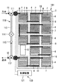
次に、図20を参照して、本発明の実施の形態4について説明する。本実施の形態は、太陽光発電パネルの裏面側に複数系統の熱媒体流通経路を設けたことを特徴としている。図20は、本発明の実施の形態4による太陽光熱ハイブリッドパネルを裏面側からみた構成図である。この図に示すように、本実施の形態の太陽光熱ハイブリッドパネル61は、前記実施の形態1とほぼ同様に、太陽光発電パネル2、太陽電池セル3、太陽熱収集器4、連通管10、熱媒体導入管11、熱媒体導出管12、接続端子13等を備えている。
Embodiment 4 FIG.
Next, a fourth embodiment of the present invention will be described with reference to FIG. The present embodiment is characterized in that a plurality of heat medium flow paths are provided on the back side of the photovoltaic power generation panel. FIG. 20 is a configuration diagram of a solar thermal hybrid panel according to Embodiment 4 of the present invention as viewed from the back side. As shown in this figure, the solar thermal hybrid panel 61 of the present embodiment is similar to the first embodiment in that the solar power generation panel 2, the solar battery cell 3, the solar heat collector 4, the communication tube 10, the heat A medium introduction pipe 11, a heat medium outlet pipe 12, a connection terminal 13, and the like are provided.

しかし、本実施の形態では、複数個の太陽熱収集器4を、例えば図20中の左半分に位置する第1のグループと、右半分に位置する第2のグループとに分けている。そして、第1のグループに属する太陽熱収集器4の熱媒体流路7同士を連通管10により接続し、該各熱媒体流路7により図20中に点線で示す第1の熱媒体流通経路Pを構成している。これと同様に、第2のグループに属する各太陽熱収集器4の熱媒体流路7は、連通管10により互いに接続されて第2の熱媒体流通経路Qを構成している。そして、熱媒体流通経路Pの最上流部及び最下流部と、熱媒体流通経路Qの最上流部及び最下流部には、それぞれ熱媒体導入管11及び熱媒体導出管12が設けられている。   However, in the present embodiment, the plurality of solar heat collectors 4 are divided into, for example, a first group located in the left half in FIG. 20 and a second group located in the right half. Then, the heat medium flow paths 7 of the solar heat collectors 4 belonging to the first group are connected to each other by the communication pipe 10, and the first heat medium flow path P indicated by a dotted line in FIG. Is configured. Similarly, the heat medium flow paths 7 of the solar heat collectors 4 belonging to the second group are connected to each other by a communication pipe 10 to form a second heat medium flow path Q. A heat medium introduction pipe 11 and a heat medium outlet pipe 12 are provided in the most upstream part and the most downstream part of the heat medium circulation path P and in the most upstream part and the most downstream part of the heat medium circulation path Q, respectively. .

このように構成される本実施の形態でも、前記実施の形態1とほぼ同様の作用効果を得ることができる。そして、特に本実施の形態によれば、太陽光発電パネル2の裏面側に複数系統の熱媒体流通経路P,Qを形成し、これらの熱媒体流通経路P,Qにそれぞれ独立して熱回収媒体を流通させることができる。これにより、太陽光発電パネル2の裏面全体を覆うように配置するのが好ましい熱媒体流通経路を、必要に応じて複数系統に分割または分岐させることができる。   In the present embodiment configured as described above, it is possible to obtain substantially the same operational effects as in the first embodiment. In particular, according to the present embodiment, a plurality of heat medium flow paths P, Q are formed on the back surface side of the photovoltaic power generation panel 2, and heat recovery is performed independently of each of the heat medium flow paths P, Q. Media can be distributed. Thereby, it is possible to divide or branch the heat medium distribution path that is preferably arranged so as to cover the entire back surface of the photovoltaic power generation panel 2 into a plurality of systems as necessary.

従って、本実施の形態によれば、前記実施の形態2の場合とほぼ同様の作用効果を得ることができる。一例を挙げると、本実施の形態では、熱媒体流通経路を経路数、経路長、熱回収媒体の流量等に応じて、太陽光熱ハイブリッドパネル61全体の熱媒体流通経路の流路抵抗(圧力損失)を適切に調整することができる。これにより、太陽光発電パネル2の形状、寸法等に対応して太陽光熱ハイブリッドパネル61の構成を変更した場合でも、パネル全体に熱回収媒体を円滑に流通させることができる。   Therefore, according to the present embodiment, it is possible to obtain substantially the same function and effect as in the second embodiment. For example, in the present embodiment, the flow resistance (pressure loss) of the heat medium distribution path of the entire solar heat hybrid panel 61 is determined according to the number of paths, the path length, the flow rate of the heat recovery medium, and the like. ) Can be adjusted appropriately. Thereby, even when the structure of the solar thermal hybrid panel 61 is changed corresponding to the shape, dimensions, etc. of the photovoltaic power generation panel 2, the heat recovery medium can be smoothly distributed throughout the panel.

また、本実施の形態では、前記第1の実施の形態に対して、太陽熱収集器4の構成を変更しないで熱媒体流通経路P,Qの分岐及び分割を行うことができる。これにより、太陽光発電パネル2及び太陽熱収集器4の連結個数、圧力損失、要求される発電容量等に応じて熱媒体流通経路P,Qの経路構造を変更する場合でも、太陽熱収集器4を設計変更せずに共通な部品として使用することができる。従って、太陽光熱ハイブリッドパネル61全体の設計及び製造を効率よく行うことができる。   Further, in the present embodiment, the heat medium flow paths P and Q can be branched and divided without changing the configuration of the solar heat collector 4 with respect to the first embodiment. Thereby, even when changing the path structure of the heat medium distribution paths P and Q according to the number of connected solar power generation panels 2 and the solar heat collector 4, pressure loss, required power generation capacity, etc., the solar heat collector 4 It can be used as a common part without changing the design. Therefore, it is possible to efficiently design and manufacture the solar thermal hybrid panel 61 as a whole.

実施の形態5.
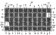
次に、図21を参照して、本発明の実施の形態5について説明する。本実施の形態は、前記実施の形態2で説明した太陽熱収集器を用いて、複数系統の熱媒体流通経路を設けたことを特徴としている。図21は、本発明の実施の形態5による太陽光熱ハイブリッドパネルを裏面側からみた構成図である。この図に示すように、本実施の形態の太陽光熱ハイブリッドパネル71は、太陽光発電パネル2、太陽電池セル3、太陽熱収集器32、連通管10、熱媒体導入管11、熱媒体導出管12、接続端子13等を備えている。
Embodiment 5 FIG.
Next, a fifth embodiment of the present invention will be described with reference to FIG. The present embodiment is characterized in that a plurality of heat medium flow paths are provided using the solar heat collector described in the second embodiment. FIG. 21 is a configuration diagram of a solar thermal hybrid panel according to Embodiment 5 of the present invention as viewed from the back side. As shown in this figure, the solar heat hybrid panel 71 of the present embodiment includes a solar power generation panel 2, a solar battery cell 3, a solar heat collector 32, a communication pipe 10, a heat medium introduction pipe 11, and a heat medium lead-out pipe 12. The connection terminal 13 is provided.

しかし、全ての太陽熱収集器32は、熱媒体流路35,36のうち一方の流路が熱媒体流通経路Pを構成し、他方の流路が熱媒体流通経路Qを構成するように、各連通管10を用いて互いに接続されている。これにより、太陽光発電パネル2の裏面側には、図21に示すように、それぞれクランク状に屈曲しつつ、互いに平行に延びた2系統の熱媒体流通経路P,Qが形成されている。そして、熱媒体流通経路Pの最上流部及び最下流部と、熱媒体流通経路Qの最上流部及び最下流部には、それぞれ熱媒体導入管11及び熱媒体導出管12が設けられている。   However, all the solar heat collectors 32 are arranged so that one of the heat medium flow paths 35 and 36 constitutes the heat medium flow path P and the other flow path forms the heat medium flow path Q. The communication pipes 10 are connected to each other. Thereby, as shown in FIG. 21, two systems of heat medium flow paths P and Q that are bent in a crank shape and extend in parallel with each other are formed on the back surface side of the photovoltaic power generation panel 2. A heat medium introduction pipe 11 and a heat medium outlet pipe 12 are provided in the most upstream part and the most downstream part of the heat medium circulation path P and in the most upstream part and the most downstream part of the heat medium circulation path Q, respectively. .

このように構成される本実施の形態でも、前記実施の形態4とほぼ同様の作用効果を得ることができる。特に、本実施の形態では、熱媒体流通経路P,Qの両方を太陽光発電パネル2の裏面全体にわたって平行に延在させることができる。これにより、個々の熱媒体流通経路P,Qの流入口及び流出口(熱媒体導入管11及び熱媒体導出管12)を相互に近接させ、配管等のレイアウトを簡略化することができる。   In the present embodiment configured as described above, substantially the same operational effects as those of the fourth embodiment can be obtained. In particular, in the present embodiment, both of the heat medium flow paths P and Q can be extended in parallel over the entire back surface of the photovoltaic power generation panel 2. Thereby, the inflow port and the outflow port (the heat medium introduction pipe 11 and the heat medium outlet pipe 12) of the individual heat medium flow paths P and Q can be brought close to each other, thereby simplifying the layout of the piping and the like.

なお、前記実施の形態4及び5は、図22及び図23に示す変形例のように、規格外の形状または寸法をもつ太陽光発電パネルに適用することもできる。ここで、図22は、本発明の実施の形態4における変形例を示す図20と同様の構成図である。太陽光熱ハイブリッドパネル81は、台形状の太陽光発電パネル82の裏面側に複数個の太陽熱収集器4が並べて配置され、各太陽熱収集器4の熱媒体流路7は、図中に点線で示すように、複数系統の熱媒体流通経路P,Qを構成している。また、図23は、本発明の実施の形態5における変形例を示す図21と同様の構成図である。太陽光熱ハイブリッドパネル91は、台形状の太陽光発電パネル92の裏面側に複数個の太陽熱収集器32が並べて配置され、各太陽熱収集器32の熱媒体流路35,36は、図中に点線で示すように、複数系統の熱媒体流通経路P,Qを構成している。   The fourth and fifth embodiments can also be applied to a photovoltaic power generation panel having a nonstandard shape or size as in the modification shown in FIGS. Here, FIG. 22 is a configuration diagram similar to FIG. 20 showing a modification of the fourth embodiment of the present invention. In the solar heat hybrid panel 81, a plurality of solar heat collectors 4 are arranged side by side on the back side of the trapezoidal solar power generation panel 82, and the heat medium flow path 7 of each solar heat collector 4 is indicated by a dotted line in the figure. As described above, a plurality of heat medium flow paths P and Q are configured. FIG. 23 is a configuration diagram similar to FIG. 21 showing a modification of the fifth embodiment of the present invention. In the solar heat hybrid panel 91, a plurality of solar heat collectors 32 are arranged side by side on the back side of the trapezoidal solar power generation panel 92, and the heat medium channels 35 and 36 of the solar heat collectors 32 are dotted lines in the figure. As shown, a plurality of heat medium flow paths P and Q are configured.

上記各変形例によっても、実施の形態4及び5と同様の作用効果を得ることができる。なお、上記実施の形態4,5及びその変形例では、2系統の熱媒体流通経路P,Qを形成する場合を例示したが、本発明はこれに限らず、3系統以上の熱媒体流通経路を形成する構成としてもよい。   Also according to each of the above modifications, it is possible to obtain the same operational effects as in the fourth and fifth embodiments. In addition, in the said Embodiment 4, 5 and its modification, the case where the two heat-medium distribution paths P and Q were formed was illustrated, However, this invention is not limited to this, Three or more heat-medium distribution paths It is good also as a structure which forms.

実施の形態6.
次に、図24及び図25を参照して、本発明の実施の形態6について説明する。本実施の形態は、太陽光熱ハイブリッドパネルの熱媒体流通経路(熱媒体流路)に圧力の異常が生じた場合に、熱回収媒体をバイパスさせる機構を備えたことを特徴としている。図24は、本発明の実施の形態6において、太陽光熱ハイブリッドパネルの一部及びソーラーシステムを示す構成図である。本実施の形態の太陽光熱ハイブリッドパネル101は、図24に示すように、前記実施の形態1とほぼ同様に構成され、太陽光発電パネル2、太陽電池セル3、連通管10、熱媒体導入管11、熱媒体導出管12等を備えている。
Embodiment 6 FIG.
Next, a sixth embodiment of the present invention will be described with reference to FIGS. The present embodiment is characterized in that a mechanism for bypassing the heat recovery medium is provided when a pressure abnormality occurs in the heat medium flow path (heat medium flow path) of the solar heat hybrid panel. FIG. 24 is a configuration diagram showing a part of a solar thermal hybrid panel and a solar system in Embodiment 6 of the present invention. As shown in FIG. 24, the solar heat hybrid panel 101 of the present embodiment is configured in substantially the same manner as in the first embodiment, and includes a solar power generation panel 2, solar cells 3, communication pipe 10, and heat medium introduction pipe. 11, a heat medium outlet tube 12 and the like.

また、太陽光熱ハイブリッドパネル101は、熱媒体流路7内の圧力が許容範囲から外れた場合に、熱媒体流路7をバイパスして熱回収媒体を熱媒体導入管11から熱媒体導出管12に流通させるためのバイパス機構110を備えている。本実施の形態のバイパス機構110は、熱媒体導入管11と熱媒体導出管12との間に設けられており、三方弁111,112、バイパス通路113、圧力開閉弁114及び逆止弁115を備えている。以下、これらの構成について説明する。   Further, the solar heat hybrid panel 101 bypasses the heat medium flow path 7 when the pressure in the heat medium flow path 7 is out of the allowable range, and transfers the heat recovery medium from the heat medium introduction pipe 11 to the heat medium outlet pipe 12. Is provided with a bypass mechanism 110 for distribution to the factory. The bypass mechanism 110 according to the present embodiment is provided between the heat medium introduction pipe 11 and the heat medium outlet pipe 12, and includes three-way valves 111 and 112, a bypass passage 113, a pressure on-off valve 114, and a check valve 115. I have. Hereinafter, these configurations will be described.

まず、三方弁111は熱媒体導入管11の途中に設けられ、三方弁112は熱媒体導出管12の途中に設けられている。なお、三方弁111,112は、熱回収媒体の流路を分岐させるためのものであり、本発明では、三方弁111,112に代えて三方継手を用いてもよい。バイパス通路113は、三方弁111,112を介して熱媒体導入管11と熱媒体導出管12とを接続している。   First, the three-way valve 111 is provided in the middle of the heat medium introduction pipe 11, and the three-way valve 112 is provided in the middle of the heat medium outlet pipe 12. The three-way valves 111 and 112 are for branching the flow path of the heat recovery medium. In the present invention, a three-way joint may be used instead of the three-way valves 111 and 112. The bypass passage 113 connects the heat medium introduction pipe 11 and the heat medium outlet pipe 12 via the three-way valves 111 and 112.

圧力開閉弁114は、熱媒体導入管11側での熱回収媒体の流入圧の変化、及び、熱媒体導出管12側での熱回収媒体の流出圧の変化により開閉するものである。より詳しく述べると、圧力開閉弁114は、熱回収媒体の流入圧と流出圧との圧力差が予め設定された許容範囲から外れた場合に開弁し、圧力差が前記上限判定値以下の場合には閉弁状態に保持されている。また、逆止弁115は、熱媒体導出管12から熱媒体導入管11に向けて熱回収媒体が逆流するのを防止するものである。一方、太陽光熱ハイブリッドパネル101は、太陽光発電及び太陽熱の回収を行うソーラーシステム120の一部を構成している。そして、三方弁111,112及び圧力開閉弁114は、ソーラーシステム120に備えられた制御装置121に接続されている。   The pressure on / off valve 114 opens and closes due to a change in the inflow pressure of the heat recovery medium on the heat medium introduction pipe 11 side and a change in the outflow pressure of the heat recovery medium on the heat medium outlet pipe 12 side. More specifically, the pressure on / off valve 114 opens when the pressure difference between the inflow pressure and the outflow pressure of the heat recovery medium is out of a preset allowable range, and the pressure difference is equal to or less than the upper limit determination value. The valve is kept closed. The check valve 115 prevents the heat recovery medium from flowing backward from the heat medium outlet pipe 12 toward the heat medium introduction pipe 11. On the other hand, the solar thermal hybrid panel 101 constitutes a part of the solar system 120 that performs solar power generation and solar heat recovery. The three-way valves 111 and 112 and the pressure opening / closing valve 114 are connected to a control device 121 provided in the solar system 120.

次に、バイパス機構110の作動について説明する。まず、熱回収媒体の詰まり、漏れ等が生じていない通常の状態では、図24に示すように、圧力開閉弁114が閉弁状態に保持されている。この状態おいて、熱媒体循環装置から供給される熱回収媒体は、熱媒体導入管11から各太陽熱収集器4の熱媒体流路7を経由して熱媒体導出管12に流出する。一方、熱回収媒体の流入圧と流出圧との圧力差が許容範囲から外れた場合には、バイパス機構110が作動し、圧力開閉弁114が開弁する。   Next, the operation of the bypass mechanism 110 will be described. First, in a normal state in which the heat recovery medium is not clogged, leaked, etc., as shown in FIG. 24, the pressure on / off valve 114 is kept closed. In this state, the heat recovery medium supplied from the heat medium circulation device flows out from the heat medium introduction pipe 11 to the heat medium outlet pipe 12 via the heat medium flow path 7 of each solar heat collector 4. On the other hand, when the pressure difference between the inflow pressure and the outflow pressure of the heat recovery medium is out of the allowable range, the bypass mechanism 110 is operated and the pressure on-off valve 114 is opened.

ここで、圧力差が許容範囲から外れる場合としては、例えば熱媒体流路7、連通管10等の目詰まり、劣化等により熱回収媒体の流入圧と流出圧との圧力差が予め設定された上限判定値を超える場合、あるいは、前記目詰まり等が原因で連通管10が外れて熱回収媒体の漏れが生じることにより前記圧力差が予め設定された下限判定値よりも小さくなる場合などが想定されている。   Here, as a case where the pressure difference deviates from the allowable range, for example, the pressure difference between the inflow pressure and the outflow pressure of the heat recovery medium is set in advance due to clogging, deterioration, or the like of the heat medium flow path 7 and the communication pipe 10. It is assumed that the upper limit judgment value is exceeded or the pressure difference becomes smaller than a preset lower judgment value because the communication pipe 10 is detached due to the clogging or the like and the heat recovery medium leaks. Has been.

図25は、図24中のバイパス機構により熱回収媒体をバイパスさせた状態を示す動作説明図である。この図に示すように、バイパス機構110が作動して圧力開閉弁114が開弁すると、熱媒体導出管12を流れる熱回収媒体は、バイパス通路113等を経由して熱媒体導入管11に流入する。即ち、熱回収媒体は、圧力の異常が生じた太陽光熱ハイブリッドパネル101をバイパスするようになり、この太陽光熱ハイブリッドパネル101の太陽熱収集器4を流れることなく、熱媒体導出管12から熱媒体循環装置(または、他の太陽光熱ハイブリッドパネル)に送られる。   FIG. 25 is an operation explanatory view showing a state in which the heat recovery medium is bypassed by the bypass mechanism in FIG. As shown in this figure, when the bypass mechanism 110 is operated and the pressure on / off valve 114 is opened, the heat recovery medium flowing through the heat medium outlet pipe 12 flows into the heat medium introduction pipe 11 via the bypass passage 113 and the like. To do. That is, the heat recovery medium bypasses the solar heat hybrid panel 101 in which the pressure abnormality has occurred, and the heat medium circulation from the heat medium outlet pipe 12 without flowing through the solar heat collector 4 of the solar heat hybrid panel 101. Sent to the device (or other solar hybrid panel).

なお、圧力開閉弁114としては、熱回収媒体の流入圧と流出圧との圧力差に応じて開閉する機械式の弁機構を用いてもよく、または、制御装置121により電気的に開閉される電磁駆動式の弁機構を用いてもよい。圧力開閉弁114として電磁駆動式の弁機構を用いる場合には、圧力センサ等により熱回収媒体の流入圧と流出圧との圧力差を検出し、検出した圧力が許容範囲から外れた場合に、圧力開閉弁114を開弁させる構成とすればよい。また、三方弁111,112は、熱回収媒体の圧力が正常な場合に熱媒体導入管11及び熱媒体導出管12を開通した状態に保持し、熱回収媒体の圧力が前記許容範囲から外れた場合には、熱媒体導入管11及び熱媒体導出管12を途中で閉塞してこれらの配管をバイパス通路113に連通させる構成とすればよい。   The pressure on / off valve 114 may be a mechanical valve mechanism that opens and closes according to the pressure difference between the inflow pressure and the outflow pressure of the heat recovery medium, or is electrically opened and closed by the control device 121. An electromagnetically driven valve mechanism may be used. When an electromagnetically driven valve mechanism is used as the pressure on / off valve 114, the pressure difference between the inflow pressure and the outflow pressure of the heat recovery medium is detected by a pressure sensor or the like, and when the detected pressure is out of the allowable range, What is necessary is just to set it as the structure which opens the pressure on-off valve 114. FIG. The three-way valves 111 and 112 keep the heat medium introduction pipe 11 and the heat medium outlet pipe 12 open when the pressure of the heat recovery medium is normal, and the pressure of the heat recovery medium is out of the allowable range. In such a case, the heat medium introduction pipe 11 and the heat medium outlet pipe 12 may be closed in the middle so that these pipes communicate with the bypass passage 113.

一方、制御装置121は、バイパス機構110が作動して熱回収媒体をバイパスさせた場合に、バイパス機構110の作動情報をソーラーシステム120の使用者、管理者等に通知する構成としてもよい。この構成において、制御装置121は、通知手段の具体例を示している。上記構成によれば、使用者、管理者等は、太陽光熱ハイブリッドパネル101の異常を速やかに把握して対処することができる。また、屋上に登らなくても、ソーラーシステム120を構成する複数の太陽光熱ハイブリッドパネル101のうち何れのパネルで異常が生じたかを判別することができる。従って、本実施の形態によれば、前記実施の形態1の効果に加えて、ソーラーシステム120のメンテナンス性を向上させることができる。   On the other hand, when the bypass mechanism 110 is activated to bypass the heat recovery medium, the control device 121 may be configured to notify the user of the solar system 120, the administrator, and the like of the operation information of the bypass mechanism 110. In this configuration, the control device 121 shows a specific example of notification means. According to the said structure, a user, an administrator, etc. can grasp | ascertain rapidly the abnormality of the solar thermal hybrid panel 101, and can cope with it. Further, it is possible to determine which of the plurality of solar thermal hybrid panels 101 constituting the solar system 120 has an abnormality without climbing on the rooftop. Therefore, according to the present embodiment, in addition to the effects of the first embodiment, the maintainability of the solar system 120 can be improved.

実施の形態7.
次に、図26乃至図28を参照して、本発明の実施の形態7について説明する。本実施の形態は、前記実施の形態6で用いたバイパス機構を2つの連通管の間に設けたことを特徴としている。図26は、本発明の実施の形態7による太陽光熱ハイブリッドパネルの一部を拡大して示す部分拡大図である。この図は、太陽光熱ハイブリッドパネルの一部の太陽熱収集器4を裏面側からみた状態を示している。
Embodiment 7 FIG.
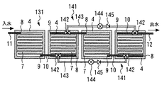
Next, a seventh embodiment of the present invention will be described with reference to FIGS. The present embodiment is characterized in that the bypass mechanism used in the sixth embodiment is provided between two communication pipes. FIG. 26 is a partially enlarged view showing a part of the solar thermal hybrid panel according to the seventh embodiment of the present invention. This figure has shown the state which looked at the solar collector 4 of a part of solar thermal hybrid panel from the back surface side.

本実施の形態の太陽光熱ハイブリッドパネル131は、2つの連通管10の間に設けられたバイパス機構141を備えている。バイパス機構141が設けられた2つの連通管10は、1つの熱媒体流通経路を構成すると共に、互いに異なる太陽熱収集器4に接続されている。以下の説明では、このような2つの連通管10を「1組の連通管10」と表記するものとする。   The solar thermal hybrid panel 131 of this embodiment includes a bypass mechanism 141 provided between the two communication pipes 10. The two communication pipes 10 provided with the bypass mechanism 141 constitute one heat medium flow path and are connected to different solar heat collectors 4. In the following description, such two communication pipes 10 are referred to as “one set of communication pipes 10”.

バイパス機構141は、熱媒体流通経路を構成する一部の熱媒体流路7内の圧力が許容範囲から外れた場合に、当該熱媒体流路7をバイパスして熱回収媒体を流通させるもので、前記実施の形態6とほぼ同様に、三方弁142,142、バイパス通路143、圧力開閉弁144及び逆止弁145を備えている。ここで、三方弁142は、1組の連通管10の途中にそれぞれ設けられ、バイパス通路143は、これらの三方弁142を介して1組の連通管10を接続している。   The bypass mechanism 141 circulates the heat recovery medium by bypassing the heat medium flow path 7 when the pressure in a part of the heat medium flow path 7 constituting the heat medium flow path is out of the allowable range. As in the sixth embodiment, three-way valves 142 and 142, a bypass passage 143, a pressure on-off valve 144, and a check valve 145 are provided. Here, the three-way valve 142 is provided in the middle of the one set of communication pipes 10, and the bypass passage 143 connects the one set of communication pipes 10 through these three-way valves 142.

圧力開閉弁144は、バイパス通路143の途中に設けられ、バイパス通路143等を介して1組の連通管10にそれぞれ接続されている。そして、圧力開閉弁144は、1組の連通管10を流れる熱回収媒体の圧力差に応じて開閉するように構成されている。詳しく述べると、圧力開閉弁144は、熱回収媒体の圧力差が予め設定された許容範囲内である場合に閉弁状態に保持され、熱回収媒体の圧力差が前記許容範囲から外れた場合に開弁する。一方、逆止弁145は、バイパス通路143の途中に設けられ、下流側の連通管10から上流側の連通管10に向けて熱回収媒体が逆流するのを防止している。   The pressure on-off valve 144 is provided in the middle of the bypass passage 143, and is connected to the set of communication pipes 10 via the bypass passage 143 and the like. The pressure open / close valve 144 is configured to open and close according to the pressure difference of the heat recovery medium flowing through the one set of communication pipes 10. More specifically, the pressure on-off valve 144 is held in a closed state when the pressure difference of the heat recovery medium is within a preset allowable range, and when the pressure difference of the heat recovery medium is out of the allowable range. Open the valve. On the other hand, the check valve 145 is provided in the middle of the bypass passage 143 to prevent the heat recovery medium from flowing backward from the downstream communication pipe 10 toward the upstream communication pipe 10.

また、本実施の形態では、2個のバイパス機構141を備えた太陽光熱ハイブリッドパネル131を例示している。2個のバイパス機構141は、それぞれ異なる1組の連通管10の間に設けられている。なお、太陽光熱ハイブリッドパネル131に設けるバイパス機構141は、1個であってもよいし、3個以上の複数個であってもよい。   Moreover, in this Embodiment, the solar thermal hybrid panel 131 provided with the two bypass mechanisms 141 is illustrated. The two bypass mechanisms 141 are provided between different sets of communication pipes 10. In addition, the bypass mechanism 141 provided in the solar thermal hybrid panel 131 may be one, and may be three or more.

次に、図27及び図28を参照して、バイパス機構141の作動について説明する。図27及び図28は、図26中のバイパス機構により熱回収媒体をバイパスさせた状態を示す動作説明図である。まず、熱回収媒体の詰まり、漏れ等が生じていない通常について説明すると、この状態では、図26に示すように、圧力開閉弁144が閉弁状態に保持されている。この状態おいて、熱媒体導入管11から上流側の太陽熱収集器4に流入した熱回収媒体は、互いに隣接する各太陽熱収集器4の熱媒体流路7を順次流通した後に、下流側の太陽熱収集器4に到達し、熱媒体導出管12から外部に流出する。   Next, the operation of the bypass mechanism 141 will be described with reference to FIGS. 27 and 28. 27 and 28 are operation explanatory views showing a state in which the heat recovery medium is bypassed by the bypass mechanism in FIG. First, the normal state in which the heat recovery medium is not clogged or leaked will be described. In this state, as shown in FIG. 26, the pressure on-off valve 144 is kept closed. In this state, the heat recovery medium that has flowed into the upstream solar heat collector 4 from the heat medium introduction pipe 11 sequentially flows through the heat medium flow paths 7 of the solar heat collectors 4 adjacent to each other, and then downstream solar heat. It reaches the collector 4 and flows out from the heat medium outlet tube 12.

一方、例えば図27中の下側に位置するバイパス機構141において、前述の理由等により熱回収媒体の圧力差が許容範囲から外れた場合には、このバイパス機構141が作動し、圧力開閉弁144が開弁する。これにより、熱回収媒体は、上流側の太陽熱収集器4からバイパス通路143を経由して下流側の太陽熱収集器4に流通し、連通管10と熱媒体流路7とからなる熱媒体流通経路のうち、圧力の異常が発生した一部の経路をバイパスするようになる。また、図28中の上側に位置するバイパス機構141が作動した場合には、熱回収媒体が熱媒体流通経路の他の一部をバイパスする。   On the other hand, for example, in the bypass mechanism 141 located on the lower side in FIG. 27, when the pressure difference of the heat recovery medium deviates from the allowable range due to the reasons described above, the bypass mechanism 141 is activated and the pressure on-off valve 144 is operated. Opens. Thereby, the heat recovery medium flows from the upstream solar heat collector 4 to the downstream solar heat collector 4 via the bypass passage 143, and the heat medium flow path including the communication pipe 10 and the heat medium flow path 7. Among these, a part of the path where the pressure abnormality occurs is bypassed. When the bypass mechanism 141 located on the upper side in FIG. 28 is activated, the heat recovery medium bypasses another part of the heat medium flow path.

このように構成される本実施の形態でも、前記実施の形態6とほぼ同様の作用効果を得ることができる。そして、特に本実施の形態では、太陽光熱ハイブリッドパネル131を構成する複数個の太陽熱収集器4のうち、圧力の異常が生じた太陽熱収集器4のみをバイパスして、他の正常な太陽熱収集器4に熱回収媒体を流通させることができる。従って、太陽熱収集器4の故障等に対して冗長性が高い太陽光熱ハイブリッドパネル131を実現することができ、ソーラーシステムの信頼性を向上させることができる。   In the present embodiment configured as described above, it is possible to obtain substantially the same operational effects as in the sixth embodiment. And especially in this Embodiment, it bypasses only the solar-heat collector 4 in which the pressure abnormality generate | occur | produced among the several solar-heat collectors 4 which comprise the solar-heat hybrid panel 131, and other normal solar-heat collectors 4 can circulate the heat recovery medium. Therefore, it is possible to realize the solar thermal hybrid panel 131 having high redundancy with respect to the failure of the solar heat collector 4 and the like, and the reliability of the solar system can be improved.

また、本実施の形態では、前記実施の形態6の場合と同様に、作動したバイパス機構141(開弁した圧力開閉弁144)の情報を制御装置121によりシステムの使用者、管理者等に通知する構成としてもよい。この構成によれば、システムの使用者、管理者等は、制御装置121から得られる情報に基いて、太陽光熱ハイブリッドパネル131の異常を速やかに把握して対処することができる。また、屋上に登らなくても、異常が生じた太陽光熱ハイブリッドパネル131及び当該パネルのうちで異常が生じた太陽熱収集器4の位置を判別することができる。従って、太陽光熱ハイブリッドパネル131及びソーラーシステムのメンテナンス性を向上させることができる。   Further, in the present embodiment, as in the case of the sixth embodiment, information on the operated bypass mechanism 141 (the opened pressure on-off valve 144) is notified to the system user, administrator, and the like by the control device 121. It is good also as composition to do. According to this configuration, a user, administrator, and the like of the system can quickly grasp and cope with the abnormality of the solar thermal hybrid panel 131 based on information obtained from the control device 121. Moreover, even if it does not climb on a rooftop, the position of the solar thermal hybrid panel 131 in which abnormality has occurred and the position of the solar heat collector 4 in which abnormality has occurred can be determined. Therefore, the maintainability of the solar thermal hybrid panel 131 and the solar system can be improved.

なお、前記実施の形態1乃至7では、それぞれ異なる構成を個別に説明したが、本発明はこれら個別の構成に限定されるものでない。即ち、本発明では、実施の形態1乃至7のうちで組合わせることが可能な2つ以上の構成を組合わせることにより、1つのシステムを実現してもよい。   In Embodiments 1 to 7, different configurations have been described individually, but the present invention is not limited to these individual configurations. That is, in the present invention, one system may be realized by combining two or more configurations that can be combined in the first to seventh embodiments.

1,1′,21,31,31′,41,51,51′,61,71,81,91,101,131 太陽光熱ハイブリッドパネル,2,22,42,82,92 太陽光発電パネル,3 太陽電池セル,4,4′,32,32′,52,52′ 太陽熱収集器,5,33,53 収集器本体,5A,33A,53A 枠状部,5B,33B,53B 閉塞板部,5C,33C,53C リブ,6,34,54 蓋板,7,35,36,55,56 熱媒体流路,8 熱媒体流入口,9 熱媒体流出口,10 連通管,11 熱媒体導入管(熱媒体導入通路),12 熱媒体導出管(熱媒体導出通路),13 接続端子,33D,53D 隔壁,37,57 熱媒体出入口,53E 隙間,110,141 バイパス機構,111,112,142 三方弁,113,143 バイパス通路,114,144 圧力開閉弁,115,145 逆止弁,120 ソーラーシステム,121 制御装置(通知手段),P,Q 熱媒体流通経路   1, 1 ', 21, 31, 31', 41, 51, 51 ', 61, 71, 81, 91, 101, 131 Solar thermal hybrid panel, 2, 22, 42, 82, 92 Solar power generation panel, 3 Solar cell, 4, 4 ', 32, 32', 52, 52 'Solar collector, 5, 33, 53 Collector body, 5A, 33A, 53A Frame, 5B, 33B, 53B Blocking plate, 5C 33C, 53C Rib, 6, 34, 54 Cover plate, 7, 35, 36, 55, 56 Heat medium flow path, 8 Heat medium inlet, 9 Heat medium outlet, 10 Communication pipe, 11 Heat medium introduction pipe ( Heat medium introduction passage), 12 Heat medium outlet pipe (heat medium outlet passage), 13 Connection terminal, 33D, 53D Partition, 37, 57 Heat medium inlet / outlet, 53E Clearance, 110, 141 Bypass mechanism, 111, 112, 142 Three-way valve , 13,143 bypass passage, 114, 144 pressure switch valve, 115,145 check valve, 120 solar system, 121 control device (notification means), P, Q fever medium flow path

Claims (9)

太陽光を受けて発電する複数個の太陽電池セルが表面側に並べて配置された板状の太陽光発電パネルと、
前記太陽光発電パネルの裏面の面積範囲内に収まるように当該裏面側に並べて配置され、前記太陽光発電パネルの裏面と平行で互いに直交する2方向に沿ってそれぞれ2つ以上並べられた複数個の太陽熱収集器と、
前記複数個の太陽熱収集器にそれぞれ設けられ、熱回収媒体が流通する熱媒体流路と、
前記複数個の太陽熱収集器の熱媒体流路同士を連通する連通管と、
を備えた太陽光熱ハイブリッドパネル。
A plate-shaped photovoltaic power generation panel in which a plurality of solar cells that generate power by receiving sunlight are arranged on the surface side;
A plurality of two or more arranged in two directions that are arranged side by side on the back surface side so as to be within the area of the back surface of the photovoltaic panel and are parallel to the back surface of the photovoltaic panel and perpendicular to each other Solar collectors,
A heat medium passage provided in each of the plurality of solar heat collectors, through which a heat recovery medium flows;
A communication pipe communicating the heat medium flow paths of the plurality of solar heat collectors;
Solar thermal hybrid panel equipped with.
前記複数個の太陽熱収集器は、互いに等しい外形状を有する構成としてなる請求項1に記載の太陽光熱ハイブリッドパネル。   The solar thermal hybrid panel according to claim 1, wherein the plurality of solar heat collectors are configured to have the same outer shape. 前記太陽光発電パネルの裏面上における前記太陽熱収集器の面積は、前記太陽電池セルの面積以下に形成してなる請求項1または2に記載の太陽光熱ハイブリッドパネル。   The solar thermal hybrid panel according to claim 1 or 2, wherein an area of the solar heat collector on a back surface of the solar power generation panel is formed to be equal to or less than an area of the solar battery cell. 互いに隣接する太陽熱収集器の間には、当該太陽熱収集器の間の熱伝導を抑制する断熱構造を設けてなる請求項1乃至3のうち何れか1項に記載の太陽光熱ハイブリッドパネル。   The solar thermal hybrid panel according to any one of claims 1 to 3, wherein a heat insulating structure that suppresses heat conduction between the solar heat collectors is provided between adjacent solar heat collectors. 1個の前記太陽熱収集器に複数個の前記熱媒体流路を設けてなる請求項1乃至4のうち何れか1項に記載の太陽光熱ハイブリッドパネル。   The solar thermal hybrid panel according to any one of claims 1 to 4, wherein a plurality of the heat medium flow paths are provided in one solar heat collector. 前記複数個の太陽熱収集器を複数のグループに分けると共に個々のグループ毎に前記連通管を用いて前記熱媒体流路を連通することにより形成した複数系統の熱媒体流通経路を備えてなる請求項1乃至5のうち何れか1項に記載の太陽光熱ハイブリッドパネル。   A plurality of heat medium flow paths formed by dividing the plurality of solar heat collectors into a plurality of groups and communicating the heat medium flow paths using the communication pipes for each group. The solar thermal hybrid panel according to any one of 1 to 5. 前記太陽熱収集器の熱媒体流路内の圧力が許容範囲から外れた場合に、前記熱媒体流路をバイパスして前記熱回収媒体を流通させるバイパス機構を備えてなる請求項1乃至6のうち何れか1項に記載の太陽光熱ハイブリッドパネル。   7. A bypass mechanism that bypasses the heat medium flow path and distributes the heat recovery medium when the pressure in the heat medium flow path of the solar heat collector is out of an allowable range. The solar thermal hybrid panel of any one of Claims. 請求項1乃至7のうち何れか1項に記載の太陽光熱ハイブリッドパネルと、
前記太陽光熱ハイブリッドパネルの前記熱媒体流路に前記熱回収媒体を循環させる熱媒体循環装置と
を備えたソーラーシステム。
A solar thermal hybrid panel according to any one of claims 1 to 7,
A solar system comprising: a heat medium circulation device that circulates the heat recovery medium in the heat medium flow path of the solar heat hybrid panel.
請求項7に記載の太陽光熱ハイブリッドパネルと、
前記太陽光熱ハイブリッドパネルの前記バイパス機構が作動して前記熱回収媒体をバイパスさせた場合に、前記バイパス機構の作動情報を通知する通知手段と、
を備えたソーラーシステム。
A solar thermal hybrid panel according to claim 7,
When the bypass mechanism of the solar thermal hybrid panel is activated to bypass the heat recovery medium, notification means for notifying operation information of the bypass mechanism;
With solar system.
JP2013069100A 2013-03-28 2013-03-28 Solar light/heat hybrid panel and solar system Pending JP2014190669A (en)

Priority Applications (1)

Application Number Priority Date Filing Date Title
JP2013069100A JP2014190669A (en) 2013-03-28 2013-03-28 Solar light/heat hybrid panel and solar system

Applications Claiming Priority (1)

Application Number Priority Date Filing Date Title
JP2013069100A JP2014190669A (en) 2013-03-28 2013-03-28 Solar light/heat hybrid panel and solar system

Publications (1)

Publication Number Publication Date
JP2014190669A true JP2014190669A (en) 2014-10-06

Family

ID=51837088

Family Applications (1)

Application Number Title Priority Date Filing Date
JP2013069100A Pending JP2014190669A (en) 2013-03-28 2013-03-28 Solar light/heat hybrid panel and solar system

Country Status (1)

Country Link
JP (1) JP2014190669A (en)

Cited By (2)

* Cited by examiner, † Cited by third party
Publication number Priority date Publication date Assignee Title
KR102431621B1 (en) * 2022-03-03 2022-08-11 주식회사 제이앤지 A new and renewable energy convergence system using an evaporative tank
WO2024028007A1 (en) * 2022-08-02 2024-02-08 Sunmaxx PVT GmbH Shaped body and method for a photovoltaic module

Citations (8)

* Cited by examiner, † Cited by third party
Publication number Priority date Publication date Assignee Title
JP2002089971A (en) * 2000-09-13 2002-03-27 Sekisui Chem Co Ltd Solar energy utilizing system
JP2002106973A (en) * 2000-10-02 2002-04-10 Sekisui Chem Co Ltd Solar heat utilizing system
JP2002295911A (en) * 2001-03-30 2002-10-09 Noritz Corp Hybrid solar heat collecting apparatus
JP2003262402A (en) * 2002-03-07 2003-09-19 Sekisui Chem Co Ltd Solar energy converter
WO2006019091A1 (en) * 2004-08-19 2006-02-23 Matsushita Electric Industrial Co., Ltd. Solar cell hybrid module
JP2008151490A (en) * 2006-12-20 2008-07-03 Electric Power Dev Co Ltd Photovoltaic power generation heat collection unit
JP2011140827A (en) * 2010-01-08 2011-07-21 Sekkei Kobo Flex:Kk Underground heat-storing house
JP2012067948A (en) * 2010-09-22 2012-04-05 Panasonic Corp Solar power utilization system

Patent Citations (8)

* Cited by examiner, † Cited by third party
Publication number Priority date Publication date Assignee Title
JP2002089971A (en) * 2000-09-13 2002-03-27 Sekisui Chem Co Ltd Solar energy utilizing system
JP2002106973A (en) * 2000-10-02 2002-04-10 Sekisui Chem Co Ltd Solar heat utilizing system
JP2002295911A (en) * 2001-03-30 2002-10-09 Noritz Corp Hybrid solar heat collecting apparatus
JP2003262402A (en) * 2002-03-07 2003-09-19 Sekisui Chem Co Ltd Solar energy converter
WO2006019091A1 (en) * 2004-08-19 2006-02-23 Matsushita Electric Industrial Co., Ltd. Solar cell hybrid module
JP2008151490A (en) * 2006-12-20 2008-07-03 Electric Power Dev Co Ltd Photovoltaic power generation heat collection unit
JP2011140827A (en) * 2010-01-08 2011-07-21 Sekkei Kobo Flex:Kk Underground heat-storing house
JP2012067948A (en) * 2010-09-22 2012-04-05 Panasonic Corp Solar power utilization system

Cited By (2)

* Cited by examiner, † Cited by third party
Publication number Priority date Publication date Assignee Title
KR102431621B1 (en) * 2022-03-03 2022-08-11 주식회사 제이앤지 A new and renewable energy convergence system using an evaporative tank
WO2024028007A1 (en) * 2022-08-02 2024-02-08 Sunmaxx PVT GmbH Shaped body and method for a photovoltaic module

Similar Documents

Publication Publication Date Title
US10305154B2 (en) Apparatus for controlling temperature of coolant in water-cooled battery system and method thereof
JP6211644B2 (en) Method and system using liquid desiccant for air conditioning and other processes
KR101568606B1 (en) Photovoltaic/thermal(PVT) module and Geo-PVT system with the PVT module
US10050584B2 (en) Cooling apparatus for solar panels
KR102296260B1 (en) Complex energy generation device using sunlight and solar heat
US20160268967A1 (en) Modular unit for attachment to solar panel
JP6767975B2 (en) Solar energy system
US20160322932A1 (en) Hybrid solar thermal system
CN103384605B (en) Thermal medium heating arrangement and possess its air conditioner for vehicles
JP2013008786A (en) Solar energy utilization system
KR20100073084A (en) Photohvoltaic-thermal hybrid apparatus and assembly method thereof
KR102352040B1 (en) heat exchanger for cooling electric element
JP2014190669A (en) Solar light/heat hybrid panel and solar system
KR102029098B1 (en) Thermoelectric generation system installed in exhaust pipe
KR102177179B1 (en) Thermoelectric based energy harvester
CN219163503U (en) Cooling liquid cooling plate
JP5747949B2 (en) Solar heat and power supply panel
JP7022487B2 (en) Solar power generation hot water supply system
WO2016098679A1 (en) Thermoelectric generation unit, thermoelectric generation device using same and mounting structure therefor, exhaust duct having same mounting structure, and engine
CN110518877A (en) Solar thermoelectric coproduction device
JP2013115224A (en) Electric power generation heat exchange hybrid panel
CN108539320A (en) Flexible-packed battery module microchannel water cooling heat exchanger
JP2014109419A (en) Solar heat hybrid panel and solar system
JP6466667B2 (en) Solar heat utilization system
GB2471844A (en) Composite solar collector

Legal Events

Date Code Title Description
A131 Notification of reasons for refusal

Free format text: JAPANESE INTERMEDIATE CODE: A131

Effective date: 20140812

A521 Request for written amendment filed

Free format text: JAPANESE INTERMEDIATE CODE: A523

Effective date: 20140917

A02 Decision of refusal

Free format text: JAPANESE INTERMEDIATE CODE: A02

Effective date: 20141014