JP2014190257A - Cam structure - Google Patents

Cam structure Download PDF

Info

Publication number
JP2014190257A
JP2014190257A JP2013066859A JP2013066859A JP2014190257A JP 2014190257 A JP2014190257 A JP 2014190257A JP 2013066859 A JP2013066859 A JP 2013066859A JP 2013066859 A JP2013066859 A JP 2013066859A JP 2014190257 A JP2014190257 A JP 2014190257A
Authority
JP
Japan
Prior art keywords
cam
camshaft
tappet
roller
oil
Prior art date
Legal status (The legal status is an assumption and is not a legal conclusion. Google has not performed a legal analysis and makes no representation as to the accuracy of the status listed.)
Granted
Application number
JP2013066859A
Other languages
Japanese (ja)
Other versions
JP6089863B2 (en
Inventor
Yusuke Kido
祐輔 木戸
Akira Yoshihara
昭 吉原
Toshihiko Oka
俊彦 岡
Shinichi Murata
真一 村田
Current Assignee (The listed assignees may be inaccurate. Google has not performed a legal analysis and makes no representation or warranty as to the accuracy of the list.)
Mitsubishi Motors Corp
Original Assignee
Mitsubishi Motors Corp
Priority date (The priority date is an assumption and is not a legal conclusion. Google has not performed a legal analysis and makes no representation as to the accuracy of the date listed.)
Filing date
Publication date
Application filed by Mitsubishi Motors Corp filed Critical Mitsubishi Motors Corp
Priority to JP2013066859A priority Critical patent/JP6089863B2/en
Publication of JP2014190257A publication Critical patent/JP2014190257A/en
Application granted granted Critical
Publication of JP6089863B2 publication Critical patent/JP6089863B2/en
Active legal-status Critical Current
Anticipated expiration legal-status Critical

Links

Images

Abstract

PROBLEM TO BE SOLVED: To reduce friction while increasing a degree of freedom in designing a cam.SOLUTION: A cam structure 10 for driving a tappet 11 connected to a basic end portion of an intake valve or an exhaust valve of an engine, includes a cam shaft 20 rotated in conjunction with a crank shaft of the engine, and a cam lobe 30 assembled to the cam shaft 20. The cam lobe 30 is composed of a base cam 31 composed of a base circular portion 31a having a mounting hole 31h for the cam shaft 20, and a valve lift portion 31b having a cutout portion 31n cut out at an intermediate portion in the width direction, of a tip portion 31c, and a roller 32 disposed on the cutout portion 31n, and provided with a crowning of the swollen shape projecting at an axial central portion on an outer peripheral face. The axial central portion of the roller 32 is rotationally moved through a center P of a top face 11a of the tappet 11.

Description

本発明は、エンジンの動弁機構を構成するローラ付きのカム構造に関する。   The present invention relates to a cam structure with a roller that constitutes a valve mechanism of an engine.

エンジンの動弁機構を構成するカムの一種として、ローラ付きのカム構造が知られている。例えば特許文献1,2には、ベース円部とバルブリフト部とを有するベースカムにローラが取り付けられたカム構造が開示されている。ローラは、バルブリフト部の先端に形成された切欠部に設けられており、その外周面の一部がバルブリフト部の外周面よりも外側に突出するように取り付けられている。   2. Description of the Related Art A cam structure with a roller is known as a kind of cam constituting an engine valve mechanism. For example, Patent Documents 1 and 2 disclose a cam structure in which a roller is attached to a base cam having a base circle portion and a valve lift portion. The roller is provided in a notch portion formed at the tip of the valve lift portion, and is attached so that a part of the outer peripheral surface protrudes outside the outer peripheral surface of the valve lift portion.

このようなローラ付きのカムは、カムシャフトの回転に伴って、まずはバルブリフト部が駆動対象であるタペットと接触してタペットを押圧し、続いてタペットとの接触位置がバルブリフト部からローラへと移り、ローラがタペット上を回転しながらタペットを押圧する。これにより、ローラ付きのカムは、ローラが付いていないカムに比べて、例えば摩擦低減による燃費向上や、低回転域でのカム駆動トルクの低減など優れた効果が得られるとされている。   In such a cam with a roller, as the camshaft rotates, the valve lift part first comes into contact with the tappet to be driven and presses the tappet, and then the contact position with the tappet moves from the valve lift part to the roller. And the roller presses the tappet while rotating on the tappet. As a result, a cam with a roller is said to have superior effects such as an improvement in fuel consumption by reducing friction and a reduction in cam driving torque in a low rotation range, compared to a cam without a roller.

ところで、カムにより駆動されるタペットは、タペットの中心ではなく、中心から偏心した位置でカムと接触するように設けられている。例えば特許文献3には、タペットの中心に対し、タペットと接触するカムローブの軸方向中心をオフセットさせた動弁装置が開示されている。このようにタペット中心からカムの接触位置を偏心させることで、カムの回転運動に伴ってタペットを中心軸回りに回転させることができる。つまり、カムとタペットの双方を回転させて、タペットとカムとの間の油膜切れを回避して摩擦を低減することができる。さらに、タペットに対してカムが同じ部分で接触し続けることを防ぐことができるため、タペットの偏摩耗を防止することもできる。   By the way, the tappet driven by the cam is provided so as to come into contact with the cam not at the center of the tappet but at a position eccentric from the center. For example, Patent Document 3 discloses a valve operating apparatus in which the axial center of a cam lobe that contacts the tappet is offset with respect to the center of the tappet. Thus, by decentering the contact position of the cam from the center of the tappet, the tappet can be rotated around the central axis in accordance with the rotational movement of the cam. That is, by rotating both the cam and the tappet, it is possible to avoid the oil film breakage between the tappet and the cam and reduce the friction. Furthermore, since the cam can be kept from contacting the tappet at the same portion, uneven wear of the tappet can be prevented.

特開2011−80372号公報JP 2011-80372 A 特開2012−202355号公報JP 2012-202355 A 特開2007−231957号公報JP 2007-231957 A

しかしながら、タペット頂面の中心から偏心した位置でカムが接触するようにカムとタペットとの位置関係を設定すると、カムとタペットとが接触する範囲(カムがタペットを押圧し続ける長さ)はタペット頂面の直径よりも短い範囲となる。そのため、カムとタペットとの接触点がタペット頂面の直径よりも短い範囲内に収まるようにカムを設計する必要があり、カム設計の自由度が低下するという課題がある。   However, when the positional relationship between the cam and the tappet is set so that the cam contacts at a position eccentric from the center of the top surface of the tappet, the range in which the cam and the tappet contact (the length that the cam continues to press the tappet) is the tappet. The range is shorter than the diameter of the top surface. Therefore, it is necessary to design the cam so that the contact point between the cam and the tappet is within a range shorter than the diameter of the top surface of the tappet, and there is a problem that the degree of freedom in cam design is reduced.

また、バルブリフト量を増大させるために、タペット頂面の直径部分を有効に利用したいという要望がある。特に、ローラ付きのカム構造の場合、ローラがタペットを押圧する長さが長いほど摩擦を低減することができるため、ローラとタペットとの接触範囲をできるだけ長くすることが望まれる。   In addition, there is a demand to effectively use the diameter portion of the top surface of the tappet in order to increase the valve lift. In particular, in the case of a cam structure with a roller, the longer the length that the roller presses the tappet, the more the friction can be reduced. Therefore, it is desirable to make the contact range between the roller and the tappet as long as possible.

本件の目的の一つは、上記のような課題に鑑み創案されたもので、カム設計の自由度を高めながら摩擦を低減することができるようにした、カム構造を提供することである。なお、この目的に限らず、後述する発明を実施するための形態に示す各構成により導かれる作用効果であって、従来の技術によっては得られない作用効果を奏することも本件の他の目的として位置づけることができる。   One of the objects of the present invention was created in view of the above problems, and is to provide a cam structure that can reduce friction while increasing the degree of freedom of cam design. The present invention is not limited to this purpose, and is a function and effect derived from each configuration shown in the embodiments for carrying out the invention described later, and other effects of the present invention are to obtain a function and effect that cannot be obtained by conventional techniques. Can be positioned.

(1)ここで開示するカム構造は、円形の頂面を有し、エンジンの吸気弁又は排気弁の基端部に接続されたタペットを駆動するカム構造であって、前記エンジンのクランクシャフトと連動して回転するカムシャフトと、前記カムシャフトに組み付けられるカムローブと、を備える。前記カムローブは、前記カムシャフトの取付孔を有するベース円部と先端部の幅方向中間部に欠成された切欠部を有するバルブリフト部とから形成されたベースカムと、前記切欠部に設けられるとともに、外周面に軸方向中心部で凸状となる膨出形状のクラウニングが形成されたローラと、から構成されている。さらに前記カムローブは、前記ローラの軸方向中心部が前記タペットの頂面の中心を通って回転移動するように設けられる。   (1) A cam structure disclosed herein is a cam structure that has a circular top surface and drives a tappet connected to a base end portion of an intake valve or an exhaust valve of an engine. A camshaft that rotates in conjunction with the camshaft; and a cam lobe that is assembled to the camshaft. The cam lobe is provided at a base cam formed from a base circular portion having a mounting hole for the camshaft and a valve lift portion having a cutout portion formed at a middle portion in the width direction of the tip portion, and the cutout portion. And a roller having a bulging-shaped crown that is convex on the outer peripheral surface at the central portion in the axial direction. Furthermore, the cam lobe is provided such that the axial center portion of the roller rotates through the center of the top surface of the tappet.

前記カムシャフトは、前記タペットの頂面の中心線(以下、タペット中心線という)上に軸心が位置するように配置されている。したがって、前記カムシャフトの軸方向と前記タペット中心線とに直交する方向から前記カム構造及び前記タペットを見たときに、前記タペット中心線と前記ローラの軸方向中心部を通る線(以下、ローラ中心線という)とが一致するように、前記カムローブが配置されている。   The camshaft is arranged such that the axis is located on the center line of the top surface of the tappet (hereinafter referred to as the tappet center line). Accordingly, when the cam structure and the tappet are viewed from a direction orthogonal to the axial direction of the camshaft and the tappet center line, a line passing through the tappet centerline and the axial center of the roller (hereinafter referred to as roller) The cam lobe is arranged so as to coincide with the center line.

(2)前記カムローブは、前記ベースカムの幅方向中心部が前記タペットの頂面の中心から偏心した位置で接触するように設けられることが好ましい。つまり、前記カムシャフトの軸方向と前記タペット中心線とに直交する方向から前記カム構造及び前記タペットを見たときに、前記タペット中心線と前記ベースカムの幅方向中心部を通る線(以下、ベースカム中心線という)とが一致しないように(偏移して)、前記カムローブが配置されていることが好ましい。   (2) It is preferable that the cam lobe is provided so that the center portion in the width direction of the base cam contacts at a position eccentric from the center of the top surface of the tappet. That is, when the cam structure and the tappet are viewed from a direction orthogonal to the axial direction of the camshaft and the tappet center line, a line passing through the center of the tappet center line and the width direction of the base cam (hereinafter referred to as the base cam). It is preferable that the cam lobe is arranged so that it does not coincide with the center line.

(3)また、前記ベースカムは、前記切欠部の幅方向両側に一対の幅の異なるヨーク部を有することが好ましい。
(4)また、前記カムローブが接触する前記タペットの頂面に球状のクラウニングが形成されていることが好ましい。
(3) Moreover, it is preferable that the said base cam has a pair of yoke part from which a width | variety differs in the width direction both sides of the said notch part.
(4) Moreover, it is preferable that spherical crowning is formed in the top surface of the tappet which the cam lobe contacts.

(5)前記カムシャフトは中空であり、前記カムシャフト及び前記ベースカムには、前記カムシャフトの中空内部と前記切欠部とを連通し、前記中空内部を流通するオイルを前記ローラへ供給するためのオイル通路が設けられ、前記オイル通路は、前記ローラの外周面に対向する前記切欠部の対向面に開口した油溜り部と、該油溜り部よりも前記中空内部側に形成され前記油溜り部よりも流路断面積が小さい絞り部と、を有することが好ましい。   (5) The camshaft is hollow, and the camshaft and the base cam communicate with the hollow interior of the camshaft and the notch, and supply oil flowing through the hollow interior to the roller. An oil passage is provided, and the oil passage is formed in an oil reservoir portion that is open on an opposing surface of the notch portion that opposes the outer peripheral surface of the roller, and is formed on the hollow inner side of the oil reservoir portion. It is preferable to have a throttle portion having a smaller channel cross-sectional area.

(6)このとき、前記油溜り部は、前記ベースカムに形成されるとともに、前記絞り部は、前記カムシャフトに形成されることが好ましい。
(7)さらに、前記油溜り部は、前記取付孔に開口するように前記ベースカムに形成された貫通孔であり、前記絞り部は、前記カムシャフトの外周面を貫通する貫通孔であることがより好ましい。
(6) At this time, it is preferable that the oil reservoir portion is formed on the base cam and the throttle portion is formed on the camshaft.
(7) Furthermore, the oil reservoir portion is a through hole formed in the base cam so as to open to the mounting hole, and the throttle portion is a through hole penetrating the outer peripheral surface of the cam shaft. More preferred.

すなわち、前記カムシャフトは中空であり、外周面を貫通して形成された絞り部を有し、前記ベースカムは、一端が前記切欠部に開口し他端が前記取付孔に開口するように貫通して形成された油溜り部を有し、前記絞り部は、前記油溜り部よりも流路断面積が大きく、前記カムローブが前記カムシャフトに組み付けられたときに前記油溜り部と連通して一つのオイル通路を形成することが好ましい。   That is, the camshaft is hollow and has a throttle portion formed so as to penetrate the outer peripheral surface, and the base cam penetrates so that one end is opened in the notch portion and the other end is opened in the mounting hole. The throttle part has a larger flow passage cross-sectional area than the oil reservoir part, and communicates with the oil reservoir part when the cam lobe is assembled to the camshaft. Preferably two oil passages are formed.

開示のカム構造によれば、ローラの軸方向中心部がタペットの頂面の中心を通って回転移動するように設けられるため、ローラとタペットとの接触範囲をタペットの頂面の最も長い部分とすることができる。そのため、カム設計の自由度を最大とすることができ、高いバルブリフト量を設定することができる。これにより、エンジンの性能を向上させることができる。また、ローラとタペットとの接触範囲を最大にすることで、摩擦を低減して燃費を向上させることができるとともに、低回転域でのカム駆動トルクを低減することができる。   According to the disclosed cam structure, the axial center portion of the roller is provided so as to rotate through the center of the top surface of the tappet, so that the contact range between the roller and the tappet is the longest portion of the top surface of the tappet. can do. Therefore, the degree of freedom in cam design can be maximized, and a high valve lift amount can be set. Thereby, the performance of the engine can be improved. In addition, by maximizing the contact range between the roller and the tappet, it is possible to reduce friction and improve fuel efficiency, and to reduce cam driving torque in a low rotation range.

また、ローラの外周面に膨出形状のクラウニングが形成されると、ローラに軸方向のスラスト荷重が発生する可能性がある。これに対して、開示のカム構造は、ローラの軸方向中心部がタペットの頂面の中心を通って回転移動するように設けられているため、ローラの軸方向のスラスト荷重の発生を抑制することができる。これにより、ローラとタペットの頂面との摩擦をより低減することができ、摩耗を抑制することができる。また、ローラの外周面に膨出形状のクラウニングが形成されているため、ミスアライメントによりローラのエッジがタペットの頂面に当たることを防ぐことができる。   Further, when a bulging-shaped crowning is formed on the outer peripheral surface of the roller, an axial thrust load may be generated on the roller. On the other hand, the disclosed cam structure is provided so that the axial center portion of the roller rotates and moves through the center of the top surface of the tappet, thereby suppressing the generation of thrust load in the axial direction of the roller. be able to. Thereby, friction with a roller and the top face of a tappet can be reduced more, and wear can be controlled. Further, since the bulging-shaped crowning is formed on the outer peripheral surface of the roller, it is possible to prevent the edge of the roller from hitting the top surface of the tappet due to misalignment.

一実施形態にかかるカム構造を説明するための図であり、(a)はローラとタペットとが接触した状態を表した図2(b)のB−B矢視断面図であり、(b)はタペット上をベースカム及びローラが移動する軌跡を表したタペット上面図である。It is a figure for demonstrating the cam structure concerning one Embodiment, (a) is a BB arrow sectional drawing of the state which the roller and tappet contacted, and (b) FIG. 4 is a top view of the tappet showing a trajectory along which the base cam and the roller move on the tappet. 一実施形態にかかるカム構造を示す模式図であり、(a)は側面図、(b)は図2(a)のA−A矢視断面図である。It is a schematic diagram which shows the cam structure concerning one Embodiment, (a) is a side view, (b) is AA arrow sectional drawing of Fig.2 (a). 一実施形態にかかるカム構造を用いた動弁機構の構成を示す断面図である。It is sectional drawing which shows the structure of the valve mechanism using the cam structure concerning one Embodiment. 一実施形態にかかるカム構造の潤滑について説明するための図であり、(a)はポンプ能力が比較的高い場合の図1(a)に対応する断面図、(b)は図4(a)のE部拡大図、(c)はポンプ能力が不足した場合の図1(a)に対応する断面図である。It is a figure for demonstrating the lubrication of the cam structure concerning one Embodiment, (a) is sectional drawing corresponding to FIG. 1 (a) in case a pump capability is comparatively high, (b) is FIG. 4 (a). (C) is a sectional view corresponding to FIG. 1 (a) when the pumping capacity is insufficient. 一実施形態にかかるカム構造のオイル通路の変形例を示す断面図であり、(a)は第一変形例、(b)は第二変形例を示す。It is sectional drawing which shows the modification of the oil path of the cam structure concerning one Embodiment, (a) shows a 1st modification, (b) shows a 2nd modification.

以下、図面を用いて実施の形態について説明する。なお、以下に示す実施形態はあくまでも例示に過ぎず、以下の実施形態で明示しない種々の変形や技術の適用を排除する意図はない。
[1.構成]
[1−1.全体構造]
図3に示すように、本実施形態にかかるカム構造10は、車両に搭載されるエンジン(何れも図示略)の動弁機構1を構成する部品の一つであり、エンジンのクランクシャフト(図示略)と連動して回転するカムシャフト20と、カムシャフト20に組み付けられるカムローブ30とを備えている。
Hereinafter, embodiments will be described with reference to the drawings. Note that the embodiment described below is merely an example, and there is no intention to exclude various modifications and technical applications that are not explicitly described in the following embodiment.
[1. Constitution]
[1-1. Overall structure]
As shown in FIG. 3, the cam structure 10 according to the present embodiment is one of the components constituting the valve mechanism 1 of an engine (not shown) mounted on a vehicle, and is a crankshaft (illustrated) of the engine. And a cam lobe 30 assembled to the camshaft 20.

動弁機構1は、カム構造10と、カム構造10によって駆動される有蓋円筒型のタペット11と、図示しないシリンダヘッドに固定される固定部12と、タペット11と固定部12との間に介設されたスプリング13とを備えている。タペット11はバルブリフターとも呼ばれ、カムシャフト20の回転運動を往復運動に変換するものである。タペット11には、エンジンの各気筒における吸気弁又は排気弁(以下、バルブ2という)の基端部が接続されている。   The valve mechanism 1 includes a cam structure 10, a covered cylindrical tappet 11 driven by the cam structure 10, a fixed portion 12 fixed to a cylinder head (not shown), and the tappet 11 and the fixed portion 12. And a provided spring 13. The tappet 11 is also called a valve lifter, and converts the rotational motion of the camshaft 20 into reciprocating motion. The tappet 11 is connected to a base end portion of an intake valve or an exhaust valve (hereinafter referred to as a valve 2) in each cylinder of the engine.

タペット11は、バルブ2側に開口が位置するように設けられ、円筒内部にバルブ2の基端部及びスプリング13の一部が配置される。タペット11は、カムローブ30が接触する円形の頂面11a(以下、タペット頂面11aという)に、カム構造10側に向かって凸となる部分球面状のクラウニングが形成されている。つまり、タペット頂面11aは、その中心Pが最もカム構造10側に突出する曲率を持った球面の一部となるように形成されている。なお、曲率円の中心は、バルブ2の軸心上に位置している。図2(b)に示すように、タペット頂面11aの中心Pを通る法線CT(以下、タペット中心線CTという)の上には、カムシャフト20の軸心SCが位置している。なお、動弁機構1の動作については後述する。   The tappet 11 is provided so that an opening is located on the valve 2 side, and a base end portion of the valve 2 and a part of the spring 13 are disposed inside the cylinder. In the tappet 11, a partial spherical crown that is convex toward the cam structure 10 side is formed on a circular top surface 11 a (hereinafter referred to as a tappet top surface 11 a) with which the cam lobe 30 contacts. That is, the tappet top surface 11a is formed such that the center P thereof is a part of a spherical surface having a curvature that protrudes most toward the cam structure 10 side. The center of the curvature circle is located on the axis of the valve 2. As shown in FIG. 2B, the axis SC of the camshaft 20 is positioned on a normal CT (hereinafter referred to as tappet centerline CT) passing through the center P of the tappet top surface 11a. The operation of the valve mechanism 1 will be described later.

[1−2.カム構造]
図2(a)及び(b)に示すように、カムシャフト20は中空のパイプで構成され、エンジンのクランクシャフトからタイミングチェーンやタイミングベルト(何れも図示略)を介して回転が伝達されて回転する。カムシャフト20の中空内部には、オイルポンプ(図示略)で圧送されたエンジンオイル(潤滑油,以下、単にオイルという)が流通する。カムシャフト20は、支持部40によりエンジン本体に支持されており、支持部40に対して回転する。そのため、カムシャフト20の支持部40が取り付けられる部分には、カムシャフト20の外周面と支持部40の内周面との接触部にオイルを供給するための貫通孔部44が設けられている。カムシャフト20の中空内部を流通するオイルは、この貫通孔部44を通じてカムシャフト20と支持部40との接触部に供給され、この接触部を潤滑する。
[1-2. Cam structure]
As shown in FIGS. 2A and 2B, the camshaft 20 is formed of a hollow pipe, and the rotation is transmitted from the crankshaft of the engine via a timing chain and a timing belt (both not shown). To do. Engine oil (lubricating oil, hereinafter simply referred to as oil) fed by an oil pump (not shown) flows through the hollow inside of the camshaft 20. The camshaft 20 is supported by the engine body by the support portion 40 and rotates with respect to the support portion 40. Therefore, a through-hole portion 44 for supplying oil to a contact portion between the outer peripheral surface of the camshaft 20 and the inner peripheral surface of the support portion 40 is provided in a portion where the support portion 40 of the camshaft 20 is attached. . Oil flowing through the hollow interior of the camshaft 20 is supplied to the contact portion between the camshaft 20 and the support portion 40 through the through-hole portion 44 and lubricates the contact portion.

カムシャフト20の軸方向には、バルブ2を開閉するためのカムローブ30が、バルブ2の個数に応じて複数固定されている。カムローブ30は、何れも同様の構成を有しているため、ここでは一つのカムローブ30を示し、その構造について説明する。   A plurality of cam lobes 30 for opening and closing the valve 2 are fixed in the axial direction of the camshaft 20 according to the number of the valves 2. Since all the cam lobes 30 have the same configuration, only one cam lobe 30 is shown here and the structure thereof will be described.

カムローブ30は、カム本体であるベースカム31と、ベースカム31に取り付けられるローラ32とから構成される。ベースカム31は、ベース円部31aとバルブリフト部31bとから形成されており、外周面が周方向全体に亘って連続している。ベース円部31aは、ベースカム31の円形の部分を意味し、中央にカムシャフト20が取り付けられる円形の孔部31h(以下、カムシャフト取付孔31hという)が形成されている。言い換えると、ベース円部31aは、カムシャフト20(カムシャフト取付孔31h)の軸心SCからの距離が一定の部分に対応する。なお、ベース円部31aとタペット頂面11aとの間には僅かな隙間が設けられており、バルブ2の不要な開閉動作が防止される。   The cam lobe 30 is composed of a base cam 31 that is a cam body and a roller 32 that is attached to the base cam 31. The base cam 31 is formed of a base circle portion 31a and a valve lift portion 31b, and the outer peripheral surface is continuous over the entire circumferential direction. The base circular portion 31a means a circular portion of the base cam 31, and a circular hole portion 31h (hereinafter referred to as a camshaft mounting hole 31h) to which the camshaft 20 is attached is formed at the center. In other words, the base circle portion 31a corresponds to a portion where the distance from the axis SC of the camshaft 20 (camshaft mounting hole 31h) is constant. A slight gap is provided between the base circle portion 31a and the tappet top surface 11a, and an unnecessary opening / closing operation of the valve 2 is prevented.

バルブリフト部31bは、ベース円部31aから突出した部分であり、タペット頂面11aを押圧してバルブ2を開閉動作させる部分である。図2(b)には、ベース円部31aとバルブリフト部31bとの境界線を二点鎖線で示している。バルブリフト部31bの図2(b)における右側は、カムローブ30が図中の矢印Cの方向に回転したときにベース円部31aの次にタペット頂面11aに対向する部分であり、バルブリフトの立上り部31b1(バルブ2が開く側)である。 The valve lift portion 31b is a portion protruding from the base circle portion 31a, and is a portion that presses the top surface 11a of the tappet to open and close the valve 2. In FIG.2 (b), the boundary line of the base circle part 31a and the valve lift part 31b is shown with the dashed-two dotted line. The right side of the valve lift portion 31b in FIG. 2B is a portion facing the tappet top surface 11a next to the base circle portion 31a when the cam lobe 30 rotates in the direction of arrow C in the figure. It is the rising portion 31b 1 (the side on which the valve 2 opens).

バルブリフト部31bの図2(b)における左側は、カムローブ30が図中の矢印Cの方向に回転したときに、ローラ32がタペット頂面11aに対向した後にタペット頂面11aに対向する部分であり、バルブリフトの立下り部31b2(バルブ2が閉じる側)である。バルブリフト部31bの立上り部31b1及び立下り部31b2の各基端部31dは、ベース円部31aとバルブリフト部31bとの境界線上にある。 The left side of the valve lift portion 31b in FIG. 2 (b) is a portion facing the tappet top surface 11a after the roller 32 faces the tappet top surface 11a when the cam lobe 30 rotates in the direction of arrow C in the drawing. Yes, it is the falling part 31b 2 of the valve lift (the side on which the valve 2 is closed). Each base end portion 31d of the rising portion 31b 1 and a fall portion 31b 2 of the valve lift portion 31b is on the boundary line between the base circle portion 31a and a valve lift portion 31b.

バルブリフト部31bは、その先端部(カムトップ部)31cに切欠部31nを有する。切欠部31nは、バルブリフト部31bの先端部31cからベース円部31aの一部にかけて、ベースカム31の幅方向(カムシャフト20が挿通される方向)の中間部に、立上り部31b1から立下り部31b2までを貫通するように切り欠いて形成された空間である。この切欠部31nには、後述するローラ32がベースカム31に対して回転自在となるように設けられる。 The valve lift part 31b has a notch part 31n at its tip part (cam top part) 31c. Notch 31n is subjected part from the tip portion 31c of the valve lift portion 31b of the base circle portion 31a, an intermediate portion in the width direction of the base cam 31 (the direction in which the cam shaft 20 is inserted), falling from the rising portion 31b 1 It is a space formed by notching so as to penetrate up to the portion 31b 2 . A roller 32 described later is provided in the notch 31n so as to be rotatable with respect to the base cam 31.

ベースカム31に欠成された切欠部31nの幅方向両側には、対向する一対のヨーク部31y,31yが形成される。対向する一対のヨーク部31y,31yは、図2(b)に示すように軸方向から見て切欠部31nと同一形状をなし、図1(a)及び図2(a)に示すように軸方向に直交する方向から見て異なる幅を有している。つまり、切欠部31nは、ベースカム31の幅方向中心から偏移した位置に形成されている。これは、ベースカム31の幅方向中心部とローラ32の軸方向中心部とを偏移させるためである。   A pair of opposing yoke portions 31y and 31y are formed on both sides in the width direction of the notch portion 31n formed in the base cam 31. The pair of opposing yoke portions 31y and 31y have the same shape as the cutout portion 31n when viewed from the axial direction as shown in FIG. 2 (b), and the shafts as shown in FIGS. 1 (a) and 2 (a). They have different widths when viewed from a direction orthogonal to the direction. That is, the notch 31n is formed at a position shifted from the center of the base cam 31 in the width direction. This is for shifting the center portion in the width direction of the base cam 31 and the center portion in the axial direction of the roller 32.

対向する一対のヨーク部31y,31yには、幅方向に貫通した孔部31m,31mが一直線上に設けられている。孔部31mは、その中心軸がベース円部31aに形成されたカムシャフト取付孔31hの軸心SCと平行になるように形成されている。この孔部31mには、ローラ32をベースカム31に取り付けるためのローラシャフト33が挿通され、かしめによりベースカム31に組み付けられて固定される。以下、この孔部31mをローラシャフト取付孔31mという。   A pair of opposing yoke portions 31y and 31y are provided with holes 31m and 31m penetrating in the width direction on a straight line. The hole 31m is formed so that its central axis is parallel to the axis SC of the camshaft mounting hole 31h formed in the base circle 31a. A roller shaft 33 for attaching the roller 32 to the base cam 31 is inserted into the hole 31m, and is assembled and fixed to the base cam 31 by caulking. Hereinafter, the hole 31m is referred to as a roller shaft mounting hole 31m.

ローラ32は、その外周面に軸方向中心部で凸となる膨出形状のクラウニングを有し、その中心にローラシャフト33が挿通される貫通孔32hを有している。言い換えると、ローラ32は、ローラ32の軸方向中心部を通る線CR(以下、ローラ中心線CRという)を通る断面で、筒面の中央が拡径方向に膨らんだ膨出形状をなしている。ローラ32は、貫通孔32hがベースカム31のヨーク部31y,31yに形成されたローラシャフト取付孔31mと重なるように切欠部31nに配置される。そして、カムシャフト20の軸心SC(カムシャフト取付孔31hの中心軸)と平行になるように、ローラシャフト33がローラシャフト取付孔31mと貫通孔32hとに挿通され、ローラ32がベースカム31に取り付けられる。   The roller 32 has a bulging-shaped crown that is convex at the axial center in the outer peripheral surface thereof, and has a through-hole 32h through which the roller shaft 33 is inserted. In other words, the roller 32 has a cross-section passing through a line CR passing through the axial center of the roller 32 (hereinafter referred to as the roller center line CR), and has a bulging shape in which the center of the cylindrical surface swells in the diameter increasing direction. . The roller 32 is disposed in the notch 31n so that the through hole 32h overlaps with the roller shaft attachment hole 31m formed in the yoke portions 31y and 31y of the base cam 31. The roller shaft 33 is inserted into the roller shaft mounting hole 31m and the through hole 32h so as to be parallel to the axis SC of the camshaft 20 (the central axis of the camshaft mounting hole 31h). It is attached.

ローラ32は、外周面の一部がバルブリフト部31bの先端部31cの外周面よりも外側に突出するように取り付けられる。また、ローラ32は、二つのヨーク部31y,31yとの隙間が略同等となるように、切欠部31nの幅方向中心部に配置される。また、ローラ32の外周面と対向する切欠部31nの対向面31fは、ローラ32側(バルブリフト部31bの先端側)に曲がった曲面形状をなし、対向面31fの曲率半径はローラ32の外周面の曲率半径よりも大きく設定されている。   The roller 32 is attached such that a part of the outer peripheral surface protrudes outside the outer peripheral surface of the tip end portion 31c of the valve lift portion 31b. The roller 32 is disposed at the center in the width direction of the notch 31n so that the gap between the two yokes 31y and 31y is substantially equal. Further, the facing surface 31f of the notch 31n facing the outer peripheral surface of the roller 32 has a curved shape bent toward the roller 32 (the tip side of the valve lift portion 31b), and the curvature radius of the facing surface 31f is the outer periphery of the roller 32. It is set larger than the radius of curvature of the surface.

ローラ32は、ベースカム31に固定されたローラシャフト33に対して回転する。そのため、ローラ32の貫通孔32hの内周面とローラシャフト33の外周面との接触面は滑りながら動く部分(摺動部)となり、適切な潤滑が必要となる。本カム構造10は、この摺動部へ潤滑油としてのオイルを供給するための後述するオイル通路34を備えている。   The roller 32 rotates with respect to the roller shaft 33 fixed to the base cam 31. Therefore, the contact surface between the inner peripheral surface of the through hole 32h of the roller 32 and the outer peripheral surface of the roller shaft 33 becomes a portion (sliding portion) that moves while sliding, and appropriate lubrication is required. The cam structure 10 includes an oil passage 34 to be described later for supplying oil as lubricating oil to the sliding portion.

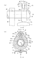
図1(a)に示すように、カムローブ30は、カムシャフト20の軸方向とタペット中心線CTとに直交する方向からカム構造10及びタペット11を見たときに、タペット中心線CTに対して、ベースカム31の幅方向中心部を通る線CB(以下、ベースカム中心線CBという)が偏移し、ローラ中心線CRが一致するように設けられている。言い換えると、タペット中心線CTとローラ中心線CRとは一致し、これらタペット中心線CT及びローラ中心線CRとベースカム中心線CBとは一致しないように設けられている(CT=CR≠CB)。   As shown in FIG. 1A, the cam lobe 30 is located with respect to the tappet center line CT when the cam structure 10 and the tappet 11 are viewed from a direction orthogonal to the axial direction of the cam shaft 20 and the tappet center line CT. A line CB passing through the center of the base cam 31 in the width direction (hereinafter referred to as a base cam center line CB) is shifted so that the roller center line CR coincides. In other words, the tappet center line CT and the roller center line CR coincide with each other, and the tappet center line CT and the roller center line CR do not coincide with the base cam center line CB (CT = CR ≠ CB).

図1(b)は、タペット頂面11a上をベースカム31及びローラ32が移動する軌跡を表したタペット11の上面図である。図1(b)中の矢印V1,V2はベースカム31の幅方向中心部の移動軌跡を示し、矢印V1は立上り部31b1,矢印V2は立下り部31b2に対応する。また、矢印Rはローラ32の軸方向中心部の移動軌跡を示す。図1(b)に示すように、ベースカム31のバルブリフト部31bがタペット頂面11aに接触するときは、ベースカム31の幅方向中心部がタペット頂面11aの中心Pから偏心し、ローラ32がタペット頂面11aに接触するときには、ローラ32の軸方向中心部がタペット頂面11aの中心Pに接触するように設けられている。 FIG. 1B is a top view of the tappet 11 showing the trajectory of the base cam 31 and the roller 32 moving on the tappet top surface 11a. Arrows V1 and V2 in FIG. 1B indicate the movement trajectory of the central portion of the base cam 31 in the width direction, the arrow V1 corresponds to the rising portion 31b 1 , and the arrow V2 corresponds to the falling portion 31b 2 . An arrow R indicates the movement locus of the central portion of the roller 32 in the axial direction. As shown in FIG. 1B, when the valve lift portion 31b of the base cam 31 contacts the tappet top surface 11a, the center portion in the width direction of the base cam 31 is eccentric from the center P of the tappet top surface 11a, and the roller 32 When contacting the tappet top surface 11a, the axial center portion of the roller 32 is provided so as to contact the center P of the tappet top surface 11a.

[1−3.オイル通路の構造]
次に、本実施形態に係るカム構造10のオイル通路34について、図1(a)及び図2(b)を用いて説明する。オイル通路34は、カムシャフト20の中空内部を流通するオイルをローラ32の摺動部へ供給するための流路であり、カムローブ30がカムシャフト20に組み付けられた状態でカムシャフト20の中空内部とベースカム31に形成された切欠部31nとが連通するように設けられている。つまり、カムシャフト20とベースカム31とには、予めオイル通路34を構成する部分がそれぞれ形成されており、カムシャフト20とカムローブ30とが組み付けられることで一つの流路(すなわちオイル通路34)を形成するようになっている。
[1-3. Oil passage structure]
Next, the oil passage 34 of the cam structure 10 according to the present embodiment will be described with reference to FIGS. 1 (a) and 2 (b). The oil passage 34 is a flow path for supplying the oil flowing through the hollow interior of the camshaft 20 to the sliding portion of the roller 32, and the hollow interior of the camshaft 20 with the cam lobe 30 assembled to the camshaft 20. And a notch 31n formed in the base cam 31 so as to communicate with each other. That is, the camshaft 20 and the base cam 31 are previously formed with portions constituting the oil passage 34, and the camshaft 20 and the cam lobe 30 are assembled to form one flow path (that is, the oil passage 34). It comes to form.

オイル通路34は、流路断面積の異なる二つの部分から構成されている。一つは、ローラ32側へ供給されるオイルの流量を制限するための絞り部34aであり、もう一つは、オイルを蓄えておくための油溜り部34bである。絞り部34aはカムシャフト20に設けられており、油溜り部34bはベースカム31に設けられている。   The oil passage 34 is composed of two parts having different channel cross-sectional areas. One is a throttle portion 34a for limiting the flow rate of oil supplied to the roller 32 side, and the other is an oil reservoir portion 34b for storing oil. The throttle part 34 a is provided on the camshaft 20, and the oil reservoir 34 b is provided on the base cam 31.

絞り部34aは、カムシャフト20の外周面を貫通する貫通孔として形成されており、一端がカムシャフト20の中空内部に開口し、他端がカムシャフト20の外周面に開口している。絞り部34aは、油溜り部34bよりもカムシャフト20の中空内部側(オイル通路34の上流側)に設けられ、カムシャフト20の中空内部からローラ32側へ供給されるオイルが最初に流入してくる部分である。絞り部34aの流路断面積は、油溜り部34bの流路断面積よりも小さく形成されている。なお、絞り部34aの流路断面積は、上記したカムシャフト20と支持部40との接触部を潤滑するための貫通孔部44の流路断面積よりも小さい。   The throttle portion 34 a is formed as a through-hole penetrating the outer peripheral surface of the camshaft 20, and one end opens into the hollow interior of the camshaft 20 and the other end opens into the outer peripheral surface of the camshaft 20. The throttle portion 34a is provided on the hollow inner side of the camshaft 20 (upstream side of the oil passage 34) than the oil reservoir portion 34b, and the oil supplied from the hollow inner portion of the camshaft 20 to the roller 32 side first flows in. It is the part that comes. The flow passage cross-sectional area of the throttle portion 34a is formed smaller than the flow passage cross-sectional area of the oil reservoir 34b. The flow passage cross-sectional area of the throttle portion 34a is smaller than the flow passage cross-sectional area of the through hole portion 44 for lubricating the contact portion between the camshaft 20 and the support portion 40 described above.

一方、油溜り部34bは、一端が切欠部31nの対向面31fに開口し、他端がカムシャフト取付孔31hに開口している。つまり、油溜り部34bはカムシャフト取付孔31hから切欠部31nの対向面31fまでを貫通する貫通孔として形成されている。油溜り部34bは、絞り部34aを流通してきたオイルが流入してローラ32側へ漏れ出ていく部分であるとともに、オイルの粘度によってローラ32側へ漏出しなかったオイルが蓄えられる部分でもある。なお、カムシャフト20とカムローブ30との組み付け時には、これら絞り部34aと油溜り部34bとが連通状態となって一つのオイル通路34を形成するように組み付けられる。   On the other hand, the oil reservoir 34b has one end opened to the facing surface 31f of the notch 31n and the other end opened to the camshaft mounting hole 31h. That is, the oil reservoir 34b is formed as a through hole that penetrates from the camshaft mounting hole 31h to the opposing surface 31f of the notch 31n. The oil reservoir 34b is a part where the oil flowing through the throttle part 34a flows in and leaks to the roller 32 side, and is also a part where oil that has not leaked to the roller 32 side due to the viscosity of the oil is stored. . When the camshaft 20 and the cam lobe 30 are assembled, the throttle portion 34a and the oil reservoir 34b are in communication with each other so as to form one oil passage 34.

[2.作用・動作]
まず、本カム構造10を備えた動弁機構1の動作について、図3を用いて説明する。図3に示すように、エンジンのクランクシャフトと連動してカムシャフト20が矢印Cの方向に回転すると、カムシャフト20とともにカムローブ30が回転する。このとき、ベースカム31のベース円部31aがタペット頂面11aと対向している間(すなわち図3の状態となる前)は、上記のようにベース円部31aとタペット頂面11aとの間に隙間が設けられているため、ベース円部31aからタペット11への押圧力は生じない。したがって、バルブ2は開閉動作をせず、スプリング13の弾性力により全閉状態に保持される。
[2. Action / Operation]
First, operation | movement of the valve mechanism 1 provided with this cam structure 10 is demonstrated using FIG. As shown in FIG. 3, when the camshaft 20 rotates in the direction of arrow C in conjunction with the crankshaft of the engine, the cam lobe 30 rotates with the camshaft 20. At this time, while the base circle portion 31a of the base cam 31 is opposed to the tappet top surface 11a (that is, before the state shown in FIG. 3), between the base circle portion 31a and the tappet top surface 11a as described above. Since the gap is provided, the pressing force from the base circle portion 31a to the tappet 11 does not occur. Therefore, the valve 2 is not opened and closed and is held in a fully closed state by the elastic force of the spring 13.

その後、カムローブ30がさらに回転して、タペット頂面11aがベースカム31のベース円部31aからバルブリフト部31bに乗り移ると、タペット11はバルブリフト部31bに押圧される。このため、スプリング13の弾性力に抗して、バルブ2がタペット11とともに押し下げられて開き始める(バルブリフトが立ち上がり始める)。   Thereafter, when the cam lobe 30 further rotates and the tappet top surface 11a is transferred from the base circle portion 31a of the base cam 31 to the valve lift portion 31b, the tappet 11 is pressed by the valve lift portion 31b. For this reason, the valve 2 is pushed down together with the tappet 11 and starts to open against the elastic force of the spring 13 (the valve lift starts to rise).

このとき、バルブリフト部31bは、図1(a)及び(b)に示すように、その幅方向中心部がタペット頂面11aの中心Pから偏心した位置でタペット頂面11aに接触するため、カムシャフト20の回転運動に伴って、タペット11はタペット中心線CTを軸として回転する。これにより、バルブリフト部31bとタペット頂面11aとの接触点が常に同一となることが防止される。   At this time, as shown in FIGS. 1A and 1B, the valve lift portion 31b contacts the tappet top surface 11a at a position where the center in the width direction is eccentric from the center P of the tappet top surface 11a. As the camshaft 20 rotates, the tappet 11 rotates about the tappet center line CT. This prevents the contact point between the valve lift portion 31b and the tappet top surface 11a from always being the same.

さらにカムローブ30が回転し、タペット頂面11aがバルブリフト部31bからローラ32に乗り移って図3の状態となると、ローラ32がタペット頂面11aの上を図中の矢印Dの方向に回転しながら移動する。つまり、ローラ32がタペット11を押圧することになる。これにより、スプリング13の弾性力に抗してバルブ2がさらに押し下げられ、バルブリフトが増加し、ついには最大のバルブリフトとなる。   When the cam lobe 30 is further rotated and the tappet top surface 11a is transferred from the valve lift 31b onto the roller 32 to the state shown in FIG. 3, the roller 32 rotates on the tappet top surface 11a in the direction of arrow D in the figure. Moving. That is, the roller 32 presses the tappet 11. As a result, the valve 2 is further pushed down against the elastic force of the spring 13, the valve lift is increased, and finally the maximum valve lift is reached.

このとき、図1(a)及び(b)に示すように、ローラ32は、その軸方向中心部がタペット頂面11aの中心Pを通って回転するため、ローラ32とタペット頂面11aとは、互いに最も突出した部分で接触することとなる。これにより、ローラ32に発生するローラ軸方向のスラスト荷重が抑制される。   At this time, as shown in FIGS. 1A and 1B, the roller 32 rotates at the center in the axial direction through the center P of the tappet top surface 11a. , They will be in contact with each other at the most protruding part. Thereby, the thrust load in the roller axial direction generated in the roller 32 is suppressed.

バルブリフト量が最大となった後は、反対にタペット頂面11aがローラ32からバルブリフト部31bに乗り移り、スプリング13の弾性力によりバルブ2は押し上げられて閉まり始める(バルブリフトが立ち下がり始める)。そして、タペット頂面11aがバルブリフト部31bからベース円部31aに乗り移ると、タペット11への押圧力はなくなり、バルブ2は全閉となる。動弁機構1は、このような動作をカムシャフト20の回転中に繰り返す。   After the valve lift amount reaches the maximum, the tappet top surface 11a is transferred from the roller 32 to the valve lift portion 31b, and the valve 2 is pushed up by the elastic force of the spring 13 and starts to close (the valve lift starts to fall). . Then, when the tappet top surface 11a is transferred from the valve lift portion 31b to the base circle portion 31a, the pressing force to the tappet 11 is lost and the valve 2 is fully closed. The valve mechanism 1 repeats such an operation while the camshaft 20 is rotating.

次に、カム構造10におけるローラ32の摺動部への潤滑について、図4(a)〜(c)を用いて説明する。図4(a)に示すように、エンジンオイルの油圧が高い場合は、オイルポンプにより圧送されたオイルは、図中白抜き矢印で示すようにカムシャフト20の中空内部を流通し、矢印で示すようにオイル通路34を通って切欠部31nに供給される。切欠部31nに供給されたオイルは、カムローブ30とタペット頂面11aとの間に図示しない油膜を形成するとともに、ローラ32の摺動部に油膜Fを形成する。   Next, lubrication of the sliding portion of the roller 32 in the cam structure 10 will be described with reference to FIGS. As shown in FIG. 4 (a), when the oil pressure of the engine oil is high, the oil pumped by the oil pump flows through the hollow interior of the camshaft 20 as indicated by the white arrow in the figure, and is indicated by the arrow. Thus, the oil is supplied to the notch 31n through the oil passage 34. The oil supplied to the notch 31n forms an oil film (not shown) between the cam lobe 30 and the tappet top surface 11a, and also forms an oil film F on the sliding portion of the roller 32.

すなわち、ローラ32はタペット頂面11aに乗り移ると回転するため、図4(b)に示すように、ローラ32の回転によるくさび効果によって、切欠部31nに供給されたオイルがローラ32の内周面とローラシャフト33の外周面との間に引き込まれる。これにより、ローラ32の内周面とローラシャフト33の外周面との間に油膜Fが形成され、この油膜Fによってローラ32の摺動部の摩擦が低減される。   That is, since the roller 32 rotates when it changes to the top surface 11a of the tappet, the oil supplied to the notch 31n is caused by the wedge effect due to the rotation of the roller 32 as shown in FIG. And the outer peripheral surface of the roller shaft 33. As a result, an oil film F is formed between the inner peripheral surface of the roller 32 and the outer peripheral surface of the roller shaft 33, and the friction of the sliding portion of the roller 32 is reduced by the oil film F.

ここで、オイル通路34の上流側(すなわち、カムシャフト20の中空内部側)には流路断面積の小さい絞り部34aが設けられているため、この絞り部34aによりオイルの流量が制限される。このため、オイルポンプの能力が比較的高くエンジンオイルの油圧が高い場合に、大量のオイルがローラ32側へ供給されて油圧が低下してしまうことを防いで、適度な量のオイルを切欠部31nに供給することができる。また、絞り部34aの下流側に位置する油溜り部34bには、切欠部31nに漏出しきらなかったオイルが蓄えられる。   Here, since the throttle portion 34a having a small channel cross-sectional area is provided on the upstream side of the oil passage 34 (that is, the hollow inner side of the camshaft 20), the flow rate of oil is limited by the throttle portion 34a. . Therefore, when the oil pump has a relatively high capacity and the oil pressure of the engine oil is high, a large amount of oil is prevented from being supplied to the roller 32 side and the oil pressure is reduced. 31n can be supplied. In addition, oil that has not leaked into the notch 31n is stored in the oil reservoir 34b located on the downstream side of the throttle portion 34a.

油溜り部34bに蓄えられたオイルは、アイドル運転時や始動時のようにエンジンの回転速度が極低回転であり、エンジンオイルの油圧が低い場合に活用される。図4(c)に示すように、エンジンオイルの油圧が低い場合であってもオイルポンプにより圧送されたオイルは、図中白抜き矢印で示すようにカムシャフト20の中空内部を流通するが、オイル通路34の絞り部34aを通過することができない。   The oil stored in the oil reservoir 34b is utilized when the engine speed is extremely low and the engine oil pressure is low, such as during idling or starting. As shown in FIG. 4 (c), even if the oil pressure of the engine oil is low, the oil pumped by the oil pump flows through the hollow interior of the camshaft 20 as shown by the white arrow in the figure. The oil passage 34 cannot pass through the throttle portion 34a.

そのため、この場合は油溜り部34bに蓄えられたオイルが、ローラ32とタペット11との接触時(すなわち、切欠部31nが油溜り部34bの下方に位置するとき)に、切欠部31nへ漏れ出す。そして、図4(b)に示すくさび効果により、上記と同様、ローラ32の摺動部に油膜Fが形成されて摩擦が低減される。また、切欠部31nからタペット頂面11aに漏出したオイルによって、タペット頂面11aにも油膜が形成される。すなわち、油溜り部34bは、エンジンオイルの油圧変動の有無にかかわらず、過不足なく安定したオイル供給を実現するためのバッファー(変化を均すもの)として機能する。   Therefore, in this case, the oil stored in the oil reservoir 34b leaks into the notch 31n when the roller 32 and the tappet 11 are in contact (that is, when the notch 31n is positioned below the oil reservoir 34b). put out. Then, due to the wedge effect shown in FIG. 4B, an oil film F is formed on the sliding portion of the roller 32 and the friction is reduced as described above. An oil film is also formed on the tappet top surface 11a by the oil leaked from the notch 31n to the tappet top surface 11a. In other words, the oil reservoir 34b functions as a buffer (equalizing change) for realizing a stable oil supply without excess or deficiency regardless of whether or not the oil pressure of the engine oil varies.

[3.効果]
したがって、本実施形態に係るカム構造10によれば、ローラ32の軸方向中心部がタペット頂面11aの中心Pを通って回転移動するように設け、ローラ32とタペット11との接触範囲をタペット頂面11aの最も長い部分とすることで、カム設計の自由度を最大とすることができる。これにより、高いバルブリフト量を設定することができ、エンジンの性能を向上させることができる。
また、図1(b)中の矢印Rの長さを可能な限りタペット11の直径に近づける(すなわち、ローラ32とタペット11との接触範囲を最大にする)ことで、摩擦を低減して燃費を向上させることができるとともに、低回転域でのカム駆動トルクを低減することができる。
[3. effect]
Therefore, according to the cam structure 10 according to the present embodiment, the center portion in the axial direction of the roller 32 is provided so as to rotate through the center P of the tappet top surface 11a, and the contact range between the roller 32 and the tappet 11 is provided. By setting it as the longest part of the top surface 11a, the freedom degree of cam design can be maximized. Thereby, a high valve lift amount can be set, and the performance of the engine can be improved.
Further, the length of the arrow R in FIG. 1B is made as close as possible to the diameter of the tappet 11 (that is, the contact range between the roller 32 and the tappet 11 is maximized), thereby reducing friction and reducing fuel consumption. Can be improved, and the cam driving torque in the low rotation range can be reduced.

また、ローラ32の外周面に膨出形状のクラウニングが形成された場合、ローラ32に軸方向のスラスト荷重が発生する可能性がある。これに対して本カム構造10は、ローラ32の軸方向中心部がタペット頂面11aの中心Pを通って回転移動するように設けられているため、ローラ32の軸方向のスラスト荷重の発生を抑制することができる。これにより、ローラ32とタペット頂面11aとの摩擦をより低減することができ、摩耗を抑制することができる。
また、ローラ32の外周面に膨出形状のクラウニングが設けられているため、ミスアラインメントによりローラ32のエッジがタペット頂面11aに当たることを防ぎ、面圧の上昇を抑制することができる。
Further, when a bulging-shaped crowning is formed on the outer peripheral surface of the roller 32, an axial thrust load may be generated on the roller 32. In contrast, the cam structure 10 is provided such that the axial center portion of the roller 32 rotates and moves through the center P of the tappet top surface 11a, so that the axial load of the roller 32 is generated. Can be suppressed. Thereby, the friction between the roller 32 and the tappet top surface 11a can be further reduced, and wear can be suppressed.
Further, since the bulging-shaped crowning is provided on the outer peripheral surface of the roller 32, it is possible to prevent the edge of the roller 32 from hitting the tappet top surface 11a due to misalignment, and to suppress an increase in surface pressure.

また、ベースカム31の幅方向中心部がタペット頂面11aの中心Pから偏心した位置で接触するようにカムローブ30が設けられているため、カムシャフト20の回転に伴ってタペット11をタペット中心線CT回りに回転させることができる。これにより、カムローブ30とタペット11との摩擦低減や、タペット頂面11a上の油膜切れを回避することができるとともに、カムローブ30が同じ箇所に接触し続けることによる偏摩耗を防止することができる。   Further, since the cam lobe 30 is provided so that the center portion in the width direction of the base cam 31 contacts at a position eccentric from the center P of the tappet top surface 11a, the tappet 11 is brought into contact with the tappet center line CT as the camshaft 20 rotates. Can be rotated around. As a result, friction between the cam lobe 30 and the tappet 11 can be reduced, and an oil film breakage on the tappet top surface 11a can be avoided, and uneven wear due to the cam lobe 30 kept in contact with the same portion can be prevented.

また、ベースカム31は、切欠部31nの幅方向両側に一対の幅の異なるヨーク部31y,31yを有するため、カムローブ30をカムシャフト20へ組み付けるときの組み付け方向の目印とすることができ、組付け性を向上させることができる。つまり、カムローブ30は、立上り部31b1と立下り部31b2とで異なる形状になっていることが多く、カムシャフト20に組み付けるときは誤った向きにしないように注意する必要がある。これに対して、本カム構造10の場合、ヨーク部31y,31yの幅が異なるため、例えば「ヨーク部31yの幅が小さい方が左側になるように、カムシャフト20にカムローブ30を取り付ける」というように予め決めておけば、正しい向きでカムローブ30を組み付けることができる。なお、ローラ中心線CRとベースカム中心線CBとのずれが大きいほど、組み付け間違いを発見しやすくすることができる。 Further, since the base cam 31 has a pair of yoke portions 31y, 31y having different widths on both sides in the width direction of the notch portion 31n, the base cam 31 can be used as a mark in the assembly direction when the cam lobe 30 is assembled to the camshaft 20. Can be improved. That is, the cam lobe 30 is often shaped differently between the rising portion 31b 1 and the falling portion 31b 2, and care must be taken when assembling the cam lobe 30 on the camshaft 20. In contrast, in the case of the present cam structure 10, since the widths of the yoke portions 31y and 31y are different, for example, “the cam lobe 30 is attached to the camshaft 20 so that the smaller width of the yoke portion 31y is on the left side”. Thus, the cam lobe 30 can be assembled in the correct orientation. Note that the larger the deviation between the roller center line CR and the base cam center line CB, the easier it is to find an assembly error.

また、カムローブ30が接触するタペット頂面11aに球状のクラウニングが形成されているため、ローラ32のクラウニングに加えてタペット11のクラウニングによってもミスアライメントをカバーすることができる。すなわち、ミスアライメントが生じた場合であっても、タペット頂面11aに形成された球状のクラウニングと、ローラ32の外周面に形成された膨出形状のクラウニングとによって、ローラ32のエッジとベースカム31のエッジとがタペット11を傷つけることを防ぐことができる。   Further, since the spherical crowning is formed on the top surface 11a of the tappet which the cam lobe 30 contacts, misalignment can be covered by the crowning of the tappet 11 in addition to the crowning of the roller 32. That is, even when misalignment occurs, the edge of the roller 32 and the base cam 31 are formed by the spherical crowning formed on the tappet top surface 11 a and the bulging crowning formed on the outer peripheral surface of the roller 32. It is possible to prevent the tappet 11 from being damaged by the edges.

また、本カム構造10は、カムシャフト20の中空内部とベースカム31の切欠部31nとを連通するオイル通路34の絞り部34aによって、ローラ32側に供給されるオイルの流量を制限することができ、エンジンオイルの油圧低下を防止することができる。これにより、オイルポンプの駆動仕事を低減することができ、さらに燃費を向上させることができる。   Further, the cam structure 10 can restrict the flow rate of oil supplied to the roller 32 side by the throttle portion 34a of the oil passage 34 that communicates the hollow interior of the camshaft 20 and the cutout portion 31n of the base cam 31. It is possible to prevent the oil pressure of the engine oil from being lowered. Thereby, the drive work of an oil pump can be reduced and a fuel consumption can be improved further.

また、オイル通路34に絞り部34aを設けることで、アイドル運転時や始動時のようにエンジンの回転速度が低くエンジンオイルの油圧が低い場合に、カムシャフト20の中空内部を流通するオイルがオイル通路34に流入できない(絞り部34aを通過できない)場合が生じうる。これに対して、本カム構造10であれば、オイル通路34の油溜り部34bにオイルを蓄えることができるため、このような油圧低下時であっても油溜り部34bから切欠部31nへオイルを供給することができる。これにより、エンジンオイルの油圧低下を防止しながら、ローラ32の摺動部の摩擦を低減することができる。   Further, by providing the throttle portion 34a in the oil passage 34, when the engine speed is low and the oil pressure of the engine oil is low, such as during idling or starting, the oil flowing through the hollow interior of the camshaft 20 is oil. There may be a case where it cannot flow into the passage 34 (it cannot pass through the throttle 34a). On the other hand, in the case of the cam structure 10, oil can be stored in the oil reservoir 34b of the oil passage 34. Therefore, even when the oil pressure is reduced, the oil is supplied from the oil reservoir 34b to the notch 31n. Can be supplied. Thereby, the friction of the sliding part of the roller 32 can be reduced while preventing the oil pressure of the engine oil from decreasing.

また、流路断面積の異なる絞り部34aと油溜り部34bとが、それぞれカムシャフト20とベースカム31とに形成されているため、カムシャフト20とカムローブ30とを圧入等で組み付ける場合に、カムシャフト20の軸方向の精度の高低にかかわらず、オイル流通性を確保することができる。つまり、組付け性の向上と潤滑性の向上とを両立することができる。また、カムシャフト20とベースカム31とにそれぞれ絞り部34aと油溜り部34bとを形成するため、容易に加工することができる。   In addition, since the throttle portion 34a and the oil reservoir portion 34b having different flow path cross-sectional areas are formed in the camshaft 20 and the base cam 31, respectively, the camshaft 20 and the cam lobe 30 can be assembled by press fitting or the like. Regardless of the accuracy of the shaft 20 in the axial direction, oil flowability can be ensured. That is, it is possible to achieve both improvement in assembling property and improvement in lubricity. Moreover, since the throttle part 34a and the oil reservoir part 34b are formed in the camshaft 20 and the base cam 31, respectively, it can process easily.

特に本実施形態では、油溜り部34bがカムシャフト取付孔31hと切欠部31nとにそれぞれ開口するようにベースカム31に形成された貫通孔である。また、絞り部34aがカムシャフト20の外周面を貫通する貫通孔である。そして、これら二つの貫通孔が組み合わされて一つのオイル通路34を構成するため、加工が容易であるとともに、オイル通路34を形成するための工数を抑制することができる。   Particularly in this embodiment, the oil reservoir 34b is a through hole formed in the base cam 31 so as to open to the camshaft mounting hole 31h and the notch 31n, respectively. Further, the throttle part 34 a is a through hole that penetrates the outer peripheral surface of the camshaft 20. And since these two through-holes combine and comprise the one oil channel | path 34, while being easy to process, the man-hour for forming the oil channel | path 34 can be suppressed.

また、カムシャフト20の支持部40が取り付けられる部分には、カムシャフト20の外周面と支持部40の内周面との接触部にオイルを供給するための貫通孔部44が設けられており、カムシャフト20と支持部40との接触部にはこの貫通孔部44を通じてオイルが供給される。カムシャフト20と支持部40とは強く接触しているため、貫通孔部44を絞り部34aの流路断面積よりも大きく形成することでカムシャフト20と支持部40との接触部の摩擦を確実に低減することができる。また、カムシャフト20と支持部40との接触部は、ローラ32の摺動部に比べて接触が強いため、オイル漏れがほとんど発生せずエンジンオイルの油圧は低下し難い。   Further, a through-hole portion 44 for supplying oil to a contact portion between the outer peripheral surface of the camshaft 20 and the inner peripheral surface of the support portion 40 is provided in a portion where the support portion 40 of the camshaft 20 is attached. The oil is supplied to the contact portion between the camshaft 20 and the support portion 40 through the through-hole portion 44. Since the camshaft 20 and the support part 40 are in strong contact with each other, the through-hole part 44 is formed larger than the flow passage cross-sectional area of the throttle part 34a, whereby the friction of the contact part between the camshaft 20 and the support part 40 is reduced. It can be surely reduced. Further, since the contact portion between the camshaft 20 and the support portion 40 has a stronger contact than the sliding portion of the roller 32, oil leakage hardly occurs and the oil pressure of the engine oil is hardly lowered.

[4.変形例]
以上、本発明の実施形態を説明したが、本発明は上記実施形態に限定されるものではなく、本発明の趣旨を逸脱しない範囲で種々変形することが可能である。
[4. Modified example]
Although the embodiments of the present invention have been described above, the present invention is not limited to the above-described embodiments, and various modifications can be made without departing from the spirit of the present invention.

[4−1.オイル通路の変形例]
例えば、上記実施形態で説明したカム構造10に設けられるオイル通路34を、図5(a)及び(b)に示すような構成に変更してもよい。
図5(a)に示すオイル通路35は、ローラ32側へ供給されるオイルの流量を制限するための絞り部35aと、オイルを蓄えておくための油溜り部35bとに加え、絞り部35aにオイルを供給する給油部35cを備えている。絞り部35a及び給油部35cはカムシャフト20に設けられ、油溜り部35bはベースカム31に設けられている。なお、油溜り部35bは上記実施形態の油溜り部34bと同一であるため、その説明は省略する。
[4-1. Modified example of oil passage]
For example, the oil passage 34 provided in the cam structure 10 described in the above embodiment may be changed to a configuration as shown in FIGS. 5 (a) and 5 (b).
The oil passage 35 shown in FIG. 5A includes a throttle portion 35a in addition to a throttle portion 35a for limiting the flow rate of oil supplied to the roller 32 and an oil reservoir portion 35b for storing oil. An oil supply part 35c is provided for supplying oil. The throttle portion 35 a and the oil supply portion 35 c are provided on the camshaft 20, and the oil reservoir portion 35 b is provided on the base cam 31. Since the oil reservoir 35b is the same as the oil reservoir 34b of the above embodiment, the description thereof is omitted.

給油部35cは、カムシャフト20の外周面を貫通する貫通孔として形成されており、一端がカムシャフト20の中空内部に開口し、他端がカムシャフト20の外周面に開口している。給油部35cは、絞り部35a及び油溜り部35bよりもカムシャフト20の中空内部側(オイル通路35の最上流部)に設けられ、カムシャフト20の中空内部からローラ32側へ供給されるオイルが最初に流入してくる部分である。給油部35cの大きさは任意であり、後述する絞り部35aの溝幅と同等か、溝幅よりもやや大きいことが好ましい。また、給油部35cの周方向位置も任意であり、カムローブ30の向きに関わらず加工が可能である。   The oil supply portion 35 c is formed as a through-hole penetrating the outer peripheral surface of the camshaft 20, and one end opens in the hollow interior of the camshaft 20 and the other end opens in the outer peripheral surface of the camshaft 20. The oil supply part 35c is provided on the hollow inner side of the camshaft 20 (the most upstream part of the oil passage 35) from the throttle part 35a and the oil reservoir 35b, and is supplied to the roller 32 side from the hollow inner part of the camshaft 20 Is the part that flows in first. The size of the oil supply portion 35c is arbitrary, and is preferably equal to or slightly larger than the groove width of the throttle portion 35a described later. Further, the circumferential position of the oil supply portion 35 c is also arbitrary, and processing is possible regardless of the orientation of the cam lobe 30.

絞り部35aは、少なくとも給油部35cと油溜り部35bとの間においてカムシャフト20の外周面に凹設された溝である。なおここでは、カムシャフト20の外周面を一周するように形成された環状溝として構成されている。溝の大きさ(つまり、溝の幅及びカムシャフト20の外周面からの深さ)は、絞り部35aの流路断面積に相当し、油溜り部35bの流路断面積よりも小さくなるように設定されている。   The throttle portion 35a is a groove that is recessed in the outer peripheral surface of the camshaft 20 at least between the oil supply portion 35c and the oil reservoir portion 35b. Here, it is configured as an annular groove formed so as to go around the outer peripheral surface of the camshaft 20. The size of the groove (that is, the width of the groove and the depth from the outer peripheral surface of the camshaft 20) corresponds to the flow passage cross-sectional area of the throttle portion 35a, and is smaller than the flow passage cross-sectional area of the oil reservoir 35b. Is set to

給油部35cは、絞り部35aの一部と重なる位置に穿孔されている。カムシャフト20とカムローブ30との組み付け時には、カムシャフト20の外周面に形成された溝としての絞り部35aが油溜り部35bと重なり、給油部35c,絞り部35a及び油溜り部35bによって一つのオイル通路35が形成されるように組み付けられる。   The oil supply part 35c is perforated at a position overlapping with a part of the throttle part 35a. When the camshaft 20 and the cam lobe 30 are assembled, the throttle part 35a as a groove formed on the outer peripheral surface of the camshaft 20 overlaps with the oil reservoir part 35b, and one oil supply part 35c, the throttle part 35a, and the oil reservoir part 35b form one. The oil passage 35 is assembled so as to be formed.

つまり、本変形例にかかるカム構造10のオイル通路35は、上流側(カムシャフト20の中空内部側)から給油部35c,絞り部35a,油溜り部35bの順に設けられており、カムシャフト20の中空内部を流通するオイルは、給油部35cを通って絞り部35aへ流入し、カムシャフト20の外周面の絞り部35aで流量が制限され、油溜り部35bへ流れる。そして、油溜り部35bから切欠部31nにオイルが供給されて、ローラ32の摺動部に油膜が形成される。   That is, the oil passage 35 of the cam structure 10 according to this modification is provided in the order of the oil supply portion 35c, the throttle portion 35a, and the oil reservoir portion 35b from the upstream side (the hollow inner side of the camshaft 20). The oil flowing through the hollow inside flows into the throttle part 35a through the oil supply part 35c, the flow rate is restricted by the throttle part 35a on the outer peripheral surface of the camshaft 20, and the oil flows into the oil reservoir part 35b. Then, oil is supplied from the oil reservoir 35b to the notch 31n, and an oil film is formed on the sliding portion of the roller 32.

したがって、本変形例にかかるカム構造10によっても、上記実施形態と同様の効果を得ることができ、さらに、絞り部35aがカムシャフト20の外周面に凹設された溝であるため、上記実施形態のように絞り部34aを貫通孔として形成する場合と比較して、絞り部35aを形成する回転方向位置をカムローブ30の向きに合わせる必要がない。また、給油部35cの回転方向位置も任意に設定可能であるため、オイル通路35の加工をより簡単にすることができる。   Therefore, the cam structure 10 according to the present modification can also obtain the same effect as that of the above embodiment, and further, since the throttle portion 35a is a groove recessed in the outer peripheral surface of the camshaft 20, the above embodiment is implemented. Compared with the case where the throttle portion 34a is formed as a through hole as in the embodiment, it is not necessary to match the rotational position of the throttle portion 35a with the direction of the cam lobe 30. Moreover, since the rotational direction position of the oil supply part 35c can also be set arbitrarily, the processing of the oil passage 35 can be simplified.

なお、絞り部35aは、少なくとも給油部35cと油溜り部35bとの間に形成されていればよく、カムシャフト20の外周面の代わりにベースカム31に形成されていてもよい。つまり、絞り部35aが、少なくとも給油部35cと油溜り部35bとの間において、ベースカム31に形成されたカムシャフト取付孔31hに凹設された溝として構成されていてもよい。このように構成されたオイル通路35であっても、上記した効果と同様の効果を得ることができる。   The throttle portion 35a only needs to be formed at least between the oil supply portion 35c and the oil reservoir 35b, and may be formed in the base cam 31 instead of the outer peripheral surface of the camshaft 20. That is, the throttle portion 35a may be configured as a groove recessed in the camshaft mounting hole 31h formed in the base cam 31 at least between the oil supply portion 35c and the oil reservoir portion 35b. Even with the oil passage 35 configured as described above, the same effects as described above can be obtained.

また、図5(b)に示すオイル通路36は、ローラ32側へ供給されるオイルの流量を制限するための絞り部36aと、オイルを蓄えておくための油溜り部36bと、絞り部36aにオイルを供給する給油部36cとを備えて構成されている。給油部36cはカムシャフト20に設けられ、絞り部36a及び油溜り部36bはベースカム31に設けられている。   The oil passage 36 shown in FIG. 5B includes a throttle part 36a for limiting the flow rate of oil supplied to the roller 32, an oil reservoir part 36b for storing oil, and a throttle part 36a. And an oil supply part 36c for supplying oil to the tank. The oil supply portion 36 c is provided on the camshaft 20, and the throttle portion 36 a and the oil reservoir portion 36 b are provided on the base cam 31.

給油部36cは、図5(a)に示す給油部35cと同様、カムシャフト20の外周面を貫通する貫通孔として形成されており、一端がカムシャフト20の中空内部に開口し、他端がカムシャフト20の外周面に開口している。給油部36cは、絞り部36a及び油溜り部36bよりもカムシャフト20の中空内部側(オイル通路36の最上流部)に設けられ、カムシャフト20の中空内部からローラ32側へ供給されるオイルが最初に流入してくる部分である。給油部36cは、後述する絞り部36aの流路断面積よりも大きい。   Like the oil supply portion 35c shown in FIG. 5A, the oil supply portion 36c is formed as a through-hole penetrating the outer peripheral surface of the camshaft 20, and one end opens into the hollow interior of the camshaft 20, and the other end is An opening is formed on the outer peripheral surface of the camshaft 20. The oil supply part 36c is provided on the hollow inner side of the camshaft 20 (the most upstream part of the oil passage 36) from the throttle part 36a and the oil reservoir part 36b, and is supplied to the roller 32 side from the hollow inner part of the camshaft 20 Is the part that flows in first. The oil supply part 36c is larger than the flow path cross-sectional area of the throttle part 36a described later.

絞り部36a及び油溜り部36bは、何れもベースカム31に形成され、一つの貫通孔を構成する。つまり、一端がカムシャフト取付孔31hに開口し、他端が切欠部31nに開口するようにベースカム31に形成された貫通孔が、長手方向で異なる径を有する段付き孔となっている。絞り部36aは、この段付き孔のうちカムシャフト20の中空内部側に位置し、カムシャフト取付孔31hに開口する。   The throttle part 36a and the oil reservoir part 36b are both formed in the base cam 31 and constitute one through hole. That is, the through hole formed in the base cam 31 so that one end opens to the camshaft mounting hole 31h and the other end opens to the notch 31n is a stepped hole having a different diameter in the longitudinal direction. The throttle part 36a is located on the hollow inner side of the camshaft 20 in the stepped hole and opens to the camshaft mounting hole 31h.

油溜り部36bは、絞り部36aよりもローラ32側に位置し、絞り部36aよりも流路断面積が大きく、切欠部31nに開口する。カムシャフト20とカムローブ30との組み付け時には、給油部36cと絞り部36aとが連通するように回転方向位置が合わせられる。すなわち、給油部36c,絞り部36a及び油溜り部36bによって一つのオイル通路36が形成されるように組み付けられる。   The oil reservoir 36b is located closer to the roller 32 than the throttle 36a, has a larger channel cross-sectional area than the throttle 36a, and opens to the notch 31n. When the camshaft 20 and the cam lobe 30 are assembled, the rotational direction positions are adjusted so that the oil supply portion 36c and the throttle portion 36a communicate with each other. That is, the oil supply portion 36c, the throttle portion 36a, and the oil reservoir portion 36b are assembled so that one oil passage 36 is formed.

つまり、本変形例にかかるカム構造10のオイル通路36は、上流側(カムシャフト20の中空内部側)から給油部36c,絞り部36a,油溜り部36bの順に設けられており、カムシャフト20の中空内部を流通するオイルは、給油部36cを通って絞り部36aへ流入し、絞り部36aで流量が制限され、油溜り部36bへ流れる。そして、油溜り部36bから切欠部31nにオイルが供給されて、ローラ32の摺動部に油膜が形成される。   That is, the oil passage 36 of the cam structure 10 according to this modification is provided in the order of the oil supply portion 36c, the throttle portion 36a, and the oil reservoir portion 36b from the upstream side (the hollow inner side of the camshaft 20). The oil flowing through the hollow inside flows into the throttle portion 36a through the oil supply portion 36c, the flow rate is restricted by the throttle portion 36a, and flows into the oil reservoir portion 36b. Then, oil is supplied from the oil reservoir 36b to the notch 31n, and an oil film is formed on the sliding portion of the roller 32.

したがって、本変形例にかかるカム構造10によっても、上記実施形態と同様の効果を得ることができ、さらに、ベースカム31に段付きの貫通孔を追加加工するだけで従来のカム構造を本カム構造10に変化させることができる。そのため、製造コストを削減することができる。また、本変形例のオイル通路36は、カムローブ30に絞り部36aが設けられているため、絞り部36aの流路長さをカムシャフト20の外周面の厚みと異なる長さに設定することができる。つまり、絞り部36aで制限されるオイルの絞り量を調整することができる。また、上記した油溜り部34b,35bに比べて、油溜り部36bの容積を小さくすることができる。   Therefore, the cam structure 10 according to the present modification can also obtain the same effects as those of the above-described embodiment. Furthermore, the conventional cam structure can be changed from the conventional cam structure only by adding a stepped through hole to the base cam 31. 10 can be changed. Therefore, the manufacturing cost can be reduced. In addition, since the oil passage 36 of the present modification is provided with the throttle portion 36 a in the cam lobe 30, the flow path length of the throttle portion 36 a can be set to a length different from the thickness of the outer peripheral surface of the camshaft 20. it can. That is, it is possible to adjust the amount of oil restricted by the restricting portion 36a. Further, the volume of the oil reservoir 36b can be reduced as compared with the oil reservoirs 34b and 35b described above.

[4−2.その他]
上記実施形態では、ベースカム31に形成された切欠部31nが、バルブリフト部31bの先端部31cの幅方向中間部のうち中央に位置している場合を例示しているが、切欠部31nの位置は中央に限られず、片寄って設けられていてもよい。また、切欠部31nがバルブリフト部31bの先端部31cからベース円部31aの一部にかけて形成されているベースカム31を例示しているが、バルブリフト部31bのみを欠成して設けられていてもよい。また、切欠部31nの対向面31fの形状も上記したものに限られず、平面であってもよい。
[4-2. Others]
In the said embodiment, although the notch part 31n formed in the base cam 31 has illustrated the case located in the center among the width direction intermediate parts of the front-end | tip part 31c of the valve lift part 31b, the position of the notch part 31n is illustrated. Is not limited to the center, and may be provided at a distance. Further, the base cam 31 is illustrated in which the notch portion 31n is formed from the tip portion 31c of the valve lift portion 31b to a part of the base circle portion 31a, but only the valve lift portion 31b is provided. Also good. Further, the shape of the facing surface 31f of the notch 31n is not limited to the above, and may be a flat surface.

また、ベースカム31の具体的な形状(リフト量及び作用角)はエンジンの仕様により適宜設定可能である。また、ローラ32の大きさやローラ32のベースカム31に対する突出量も図示したものに限られず、適宜設定可能である。   The specific shape (lift amount and working angle) of the base cam 31 can be set as appropriate according to the engine specifications. Further, the size of the roller 32 and the protruding amount of the roller 32 with respect to the base cam 31 are not limited to those shown in the figure, and can be set as appropriate.

また、上記実施形態では、ベースカム31の幅方向中心部がタペット頂面11aの中心Pから偏心した位置で接触するようにカムローブ30が設けられているが、ベースカム中心線CBとタペット中心線CTとが一致するようにカムローブ30が設けられていてもよい。すなわち、ベースカム31の幅方向中心部に切欠部31nを設けて、ローラ32の軸方向中心部とベースカム31の幅方向中心部とが一致するようにしてもよい。また、切欠部31nの幅方向両側に設けられる一対のヨーク部31y,31yが同一の幅で形成されていてもよい。   Further, in the above embodiment, the cam lobe 30 is provided so that the center portion in the width direction of the base cam 31 is in contact with the position offset from the center P of the tappet top surface 11a. However, the base cam center line CB and the tappet center line CT The cam lobes 30 may be provided so as to match. That is, a notch 31n may be provided at the center of the base cam 31 in the width direction so that the center of the roller 32 in the axial direction matches the center of the base cam 31 in the width direction. Further, the pair of yoke portions 31y and 31y provided on both sides in the width direction of the cutout portion 31n may be formed with the same width.

また、タペット11の頂面11aに球状のクラウニングが形成されていなくてもよい。すなわち、タペット11の頂面が平面状であってもよく、この場合、タペット中心線CTは中心Pを通りタペット頂面に垂直な線となる。   Further, the spherical crowning may not be formed on the top surface 11 a of the tappet 11. That is, the top surface of the tappet 11 may be planar. In this case, the tappet center line CT is a line that passes through the center P and is perpendicular to the top surface of the tappet.

また、上記実施形態では、ローラ32がベースカム31に固定されたローラシャフト33に対して回転するカム構造10を説明したが、ローラ32とローラシャフト33とが固定され、ローラシャフト33がベースカム31に対して回転するカム構造であってもよい。また、ローラ32がローラシャフト33に対して回転自在であり、さらにローラシャフト33もベースカム31に対して回転自在であってもよい。このような場合であっても、切欠部31nにオイルが供給されることにより摺動部に油膜が形成され、摩擦を低減することができる。   In the above embodiment, the cam structure 10 in which the roller 32 rotates with respect to the roller shaft 33 fixed to the base cam 31 has been described. However, the roller 32 and the roller shaft 33 are fixed, and the roller shaft 33 is attached to the base cam 31. It may be a cam structure that rotates relative to it. Further, the roller 32 may be rotatable with respect to the roller shaft 33, and the roller shaft 33 may also be rotatable with respect to the base cam 31. Even in such a case, an oil film is formed on the sliding portion by supplying oil to the notch 31n, and friction can be reduced.

1 動弁機構
2 バルブ(吸気弁又は排気弁)
10 カム構造
11 タペット
20 カムシャフト
30 カムローブ
31 ベースカム
31a ベース円部
31b バルブリフト部
31c 先端部
31f 対向面
31h カムシャフト取付孔
31m ローラシャフト取付孔
31n 切欠部
31y ヨーク部
32 ローラ
32h 貫通孔
33 ローラシャフト
34,35,36 オイル通路
34a,35a,36a 絞り部
34b,35b,36b 油溜り部
35c,36c 給油部
40 支持部
44 貫通孔部
1 Valve mechanism 2 Valve (intake or exhaust valve)
DESCRIPTION OF SYMBOLS 10 Cam structure 11 Tappet 20 Cam shaft 30 Cam lobe 31 Base cam 31a Base circle part 31b Valve lift part 31c Tip part 31f Opposing surface 31h Cam shaft attachment hole 31m Roller shaft attachment hole 31n Notch part 31y York part 32 Roller 32h Through-hole 33 Roller shaft 34, 35, 36 Oil passage 34a, 35a, 36a Throttle part 34b, 35b, 36b Oil reservoir 35c, 36c Oil supply part 40 Support part 44 Through-hole part

Claims (7)

円形の頂面を有し、エンジンの吸気弁又は排気弁の基端部に接続されたタペットを駆動するカム構造であって、
前記エンジンのクランクシャフトと連動して回転するカムシャフトと、
前記カムシャフトに組み付けられるカムローブと、を備え、
前記カムローブは、
前記カムシャフトの取付孔を有するベース円部と、先端部の幅方向中間部に欠成された切欠部を有するバルブリフト部とから形成されたベースカムと、
前記切欠部に設けられるとともに、外周面に軸方向中心部で凸となる膨出形状のクラウニングが形成されたローラと、から構成され、
前記ローラの軸方向中心部が前記タペットの頂面の中心を通って回転移動するように設けられる
ことを特徴とする、カム構造。
A cam structure for driving a tappet having a circular top surface and connected to a proximal end of an intake valve or an exhaust valve of an engine;
A camshaft that rotates in conjunction with the crankshaft of the engine;
A cam lobe assembled to the camshaft,
The cam lobe is
A base cam formed from a base circle portion having a mounting hole of the camshaft, and a valve lift portion having a notch portion formed in a middle portion in the width direction of the tip portion;
The roller is provided with the bulging-shaped crowning that is provided at the notch and is convex on the outer peripheral surface at the axial center,
A cam structure characterized in that an axially central portion of the roller is provided to rotate through the center of the top surface of the tappet.
前記カムローブは、前記ベースカムの幅方向中心部が前記タペットの頂面の中心から偏心した位置で接触するように設けられる
ことを特徴とする、請求項1記載のカム構造。
2. The cam structure according to claim 1, wherein the cam lobe is provided so that a center portion in a width direction of the base cam contacts at a position eccentric from a center of a top surface of the tappet.
前記ベースカムは、前記切欠部の幅方向両側に一対の幅の異なるヨーク部を有する
ことを特徴とする、請求項1又は2記載のカム構造。
The cam structure according to claim 1 or 2, wherein the base cam has a pair of yoke portions having different widths on both sides in the width direction of the notch portion.
前記カムローブが接触する前記タペットの頂面に球状のクラウニングが形成されている
ことを特徴とする、請求項1〜3の何れか1項に記載のカム構造。
The cam structure according to any one of claims 1 to 3, wherein a spherical crowning is formed on a top surface of the tappet that is in contact with the cam lobe.
前記カムシャフトは中空であり、
前記カムシャフト及び前記ベースカムには、前記カムシャフトの中空内部と前記切欠部とを連通し、前記中空内部を流通するオイルを前記ローラへ供給するためのオイル通路が設けられ、
前記オイル通路は、前記ローラの外周面に対向する前記切欠部の対向面に開口した油溜り部と、該油溜り部よりも前記中空内部側に形成され前記油溜り部よりも流路断面積が小さい絞り部と、を有する
ことを特徴とする、請求項1〜4の何れか1項に記載のカム構造。
The camshaft is hollow;
The camshaft and the base cam are provided with an oil passage for communicating the hollow interior of the camshaft and the notch, and supplying oil flowing through the hollow interior to the roller,
The oil passage is formed in an oil reservoir opening on an opposed surface of the cutout portion facing the outer peripheral surface of the roller, and is formed on the hollow inner side of the oil reservoir and formed in a flow passage cross-sectional area than the oil reservoir. The cam structure according to any one of claims 1 to 4, further comprising a throttle portion having a small diameter.
前記油溜り部は、前記ベースカムに形成されるとともに、
前記絞り部は、前記カムシャフトに形成される
ことを特徴とする、請求項5記載のカム構造。
The oil reservoir is formed on the base cam,
The cam structure according to claim 5, wherein the throttle portion is formed on the camshaft.
前記油溜り部は、前記取付孔に開口するように前記ベースカムに形成された貫通孔であり、
前記絞り部は、前記カムシャフトの外周面を貫通する貫通孔である
ことを特徴とする、請求項6記載のカム構造。
The oil reservoir is a through hole formed in the base cam so as to open to the mounting hole,
The cam structure according to claim 6, wherein the throttle portion is a through-hole penetrating an outer peripheral surface of the camshaft.
JP2013066859A 2013-03-27 2013-03-27 Cam structure Active JP6089863B2 (en)

Priority Applications (1)

Application Number Priority Date Filing Date Title
JP2013066859A JP6089863B2 (en) 2013-03-27 2013-03-27 Cam structure

Applications Claiming Priority (1)

Application Number Priority Date Filing Date Title
JP2013066859A JP6089863B2 (en) 2013-03-27 2013-03-27 Cam structure

Publications (2)

Publication Number Publication Date
JP2014190257A true JP2014190257A (en) 2014-10-06
JP6089863B2 JP6089863B2 (en) 2017-03-08

Family

ID=51836761

Family Applications (1)

Application Number Title Priority Date Filing Date
JP2013066859A Active JP6089863B2 (en) 2013-03-27 2013-03-27 Cam structure

Country Status (1)

Country Link
JP (1) JP6089863B2 (en)

Citations (5)

* Cited by examiner, † Cited by third party
Publication number Priority date Publication date Assignee Title
JPH0749017A (en) * 1994-03-31 1995-02-21 Mitsubishi Motors Corp Roller rocker arm lubricating structure
US5694892A (en) * 1996-05-24 1997-12-09 Ford Motor Company Roller camshaft for internal combustion engine
JP2003106111A (en) * 2001-10-01 2003-04-09 Nsk Ltd Tappet roller
JP2012072671A (en) * 2010-09-28 2012-04-12 Hitachi Automotive Systems Ltd Valve lifter for internal combustion engine
JP2012202355A (en) * 2011-03-28 2012-10-22 Mitsubishi Motors Corp Cam structure

Patent Citations (5)

* Cited by examiner, † Cited by third party
Publication number Priority date Publication date Assignee Title
JPH0749017A (en) * 1994-03-31 1995-02-21 Mitsubishi Motors Corp Roller rocker arm lubricating structure
US5694892A (en) * 1996-05-24 1997-12-09 Ford Motor Company Roller camshaft for internal combustion engine
JP2003106111A (en) * 2001-10-01 2003-04-09 Nsk Ltd Tappet roller
JP2012072671A (en) * 2010-09-28 2012-04-12 Hitachi Automotive Systems Ltd Valve lifter for internal combustion engine
JP2012202355A (en) * 2011-03-28 2012-10-22 Mitsubishi Motors Corp Cam structure

Also Published As

Publication number Publication date
JP6089863B2 (en) 2017-03-08

Similar Documents

Publication Publication Date Title
JP6298241B2 (en) Cam structure
CN103038458A (en) Variable valve device of internal combustion engine
JP2012202355A (en) Cam structure
US7980216B2 (en) Rocker arm assembly having slider roller oil pumping features
KR20040107390A (en) Rocker shaft
JP6089863B2 (en) Cam structure
JP5627158B1 (en) Cam follower device
US5913292A (en) Variable valve timing and lift mechanism of internal combustion engine
JP6115240B2 (en) Cam structure
JP4888337B2 (en) Internal combustion engine fuel pump
JP2014190259A (en) Cam structure
JP3899616B2 (en) Valve timing adjusting device for internal combustion engine
JP2008267511A (en) Joint mechanism
JP5278702B2 (en) Variable valve operating device for internal combustion engine
JP6330466B2 (en) Camshaft bearing lubrication structure
JP2014114913A (en) Rocker arm bearing
JP2013096290A (en) Variable displacement type internal gear pump
JP6278105B2 (en) Cam structure
JP6102985B2 (en) Cam structure
JP2010116822A (en) Lubricating device for valve train
JP5790727B2 (en) Cam structure
JP2008274908A (en) Camshaft of internal combustion engine
JP2014185725A (en) Rolling bearing device
JP2010024843A (en) Lubricating device of dynamic valve system
JP2005248798A (en) Lubricating device for variable valve system

Legal Events

Date Code Title Description
A621 Written request for application examination

Free format text: JAPANESE INTERMEDIATE CODE: A621

Effective date: 20151218

A977 Report on retrieval

Free format text: JAPANESE INTERMEDIATE CODE: A971007

Effective date: 20160826

A131 Notification of reasons for refusal

Free format text: JAPANESE INTERMEDIATE CODE: A131

Effective date: 20160830

A521 Written amendment

Free format text: JAPANESE INTERMEDIATE CODE: A523

Effective date: 20161028

TRDD Decision of grant or rejection written
A01 Written decision to grant a patent or to grant a registration (utility model)

Free format text: JAPANESE INTERMEDIATE CODE: A01

Effective date: 20170110

A61 First payment of annual fees (during grant procedure)

Free format text: JAPANESE INTERMEDIATE CODE: A61

Effective date: 20170123

R151 Written notification of patent or utility model registration

Ref document number: 6089863

Country of ref document: JP

Free format text: JAPANESE INTERMEDIATE CODE: R151

S531 Written request for registration of change of domicile

Free format text: JAPANESE INTERMEDIATE CODE: R313531

R350 Written notification of registration of transfer

Free format text: JAPANESE INTERMEDIATE CODE: R350