JP2014190098A - Rainwater storing piping structure and weir member used for the same - Google Patents
Rainwater storing piping structure and weir member used for the same Download PDFInfo
- Publication number
- JP2014190098A JP2014190098A JP2013067820A JP2013067820A JP2014190098A JP 2014190098 A JP2014190098 A JP 2014190098A JP 2013067820 A JP2013067820 A JP 2013067820A JP 2013067820 A JP2013067820 A JP 2013067820A JP 2014190098 A JP2014190098 A JP 2014190098A
- Authority
- JP
- Japan
- Prior art keywords
- rainwater
- port
- weir
- discharge port
- piping structure
- Prior art date
- Legal status (The legal status is an assumption and is not a legal conclusion. Google has not performed a legal analysis and makes no representation as to the accuracy of the status listed.)
- Granted
Links
Images
Classifications
-
- Y—GENERAL TAGGING OF NEW TECHNOLOGICAL DEVELOPMENTS; GENERAL TAGGING OF CROSS-SECTIONAL TECHNOLOGIES SPANNING OVER SEVERAL SECTIONS OF THE IPC; TECHNICAL SUBJECTS COVERED BY FORMER USPC CROSS-REFERENCE ART COLLECTIONS [XRACs] AND DIGESTS
- Y02—TECHNOLOGIES OR APPLICATIONS FOR MITIGATION OR ADAPTATION AGAINST CLIMATE CHANGE
- Y02A—TECHNOLOGIES FOR ADAPTATION TO CLIMATE CHANGE
- Y02A20/00—Water conservation; Efficient water supply; Efficient water use
- Y02A20/108—Rainwater harvesting
Landscapes
- Sewage (AREA)
Abstract
【課題】既設の配管設備にも簡易な施工で実施することができ、メンテナンス性も非常に良好な雨水貯溜配管構造を提供する。
【解決手段】雨水桝1に接続される排水管2の内部に雨水を貯溜する雨水貯溜配管構造であって、雨水桝1の流入口1aに、上方が開口した堰3を設け、堰3に排出口30bを形成すると共に、該排出口30bに脱着可能な閉塞部材4を取付けた構成とする。排水管2から流入した雨水は、堰3により堰止められて、それよりも上流側の排水管2内部に雨水が貯溜されていき、その貯溜した雨水を有効利用することができる。メンテナンス時は、堰3の排出口30bに脱着可能な閉塞部材4を取付けたことにより、排水管2内部に貯溜された雨水を、容易且つ迅速に排出することができる。
【選択図】図2The present invention provides a rainwater storage piping structure that can be applied to existing piping equipment with simple construction and has excellent maintainability.
A rainwater storage pipe structure for storing rainwater inside a drain pipe 2 connected to a rainwater tank 1 is provided with a weir 3 having an upper opening at an inlet 1 a of the rainwater tank 1. A discharge port 30b is formed, and a detachable closing member 4 is attached to the discharge port 30b. The rainwater flowing in from the drain pipe 2 is stopped by the weir 3, and the rain water is stored in the drain pipe 2 on the upstream side of the weir 3, so that the stored rain water can be used effectively. At the time of maintenance, by attaching the detachable closing member 4 to the discharge port 30b of the weir 3, the rainwater stored in the drain pipe 2 can be discharged easily and quickly.
[Selection] Figure 2
Description
本発明は、雨水桝に接続された排水管の内部に雨水を貯溜し、その貯溜した雨水を植物の水やり等に有効利用できるようにした雨水貯溜配管構造とそれに用いる堰部材に関するものである。 The present invention relates to a rainwater storage piping structure for storing rainwater inside a drain pipe connected to a rainwater trough, and effectively using the stored rainwater for watering a plant, and a weir member used therefor. .
近年、道路や空き地(駐車場等)の舗装化が急速に進み、未舗装部分の殆どない都市化の進んだ地域が増えてきている。このような地域では、雨水が殆ど地中に浸透することなく、道路の側溝や下水道排水管などを通じて河川へ流れ込むため、短時間で河川の容量を超えて所謂、都市型洪水を引き起し、社会問題となってきている。その一方で、乾期には雨が殆ど降らず、各地で取水制限が実施されている実態がある。これらの問題は、地球温暖化が要因とも言われる昨今の異常気象に伴い、これから益々深刻化していくものと思われる。 In recent years, roads and vacant lots (parking lots, etc.) have been paved rapidly, and urbanized areas with almost no unpaved parts are increasing. In such an area, almost no rainwater penetrates into the ground and flows into the river through the side ditch of the road or sewer drainage pipe, etc. It has become a social problem. On the other hand, there is almost no rain during the dry season, and water intake restrictions are being implemented in various places. These problems are expected to become increasingly serious with the recent extreme weather, which is said to be caused by global warming.
集中豪雨時の河川や下水道施設への負荷を低減するため、宅地内の最終雨水桝と公共用雨水桝との間にオーバーフロー部材を、その下縁を宅内集水経路よりも上方に位置させて配設することにより、宅地内の最終雨水桝内と宅内集水経路内に、雨水を一定量貯溜可能とした住宅用雨水貯溜システムが提案された(特許文献1)。 In order to reduce the load on rivers and sewerage facilities during torrential rain, an overflow member is placed between the final rainwater catchment in the residential land and the public rainwater catchment, and the lower edge is positioned above the water collection route in the home. A residential rainwater storage system has been proposed that allows a certain amount of rainwater to be stored in the final rainwater basin in the residential land and in the residential water collecting route by arranging (Patent Document 1).
この住宅用雨水貯溜システムは、宅内集水経路の高さに合わせて、オーバーフロー部材にオリフィスを形成し、宅地内の最終雨水桝と宅内集水経路内に貯溜した雨水を上記オリフィスから徐々に排出するようになっている。これにより、家屋に降った雨水が、宅内集水経路を経て道路の側溝や下水道排水管に一気に流出するのを抑制し、集中豪雨時の河川や下水道施設への負荷を低減させることができるようになっている。 In this residential rainwater storage system, an orifice is formed in the overflow member according to the height of the residential water collection channel, and the rainwater stored in the final rainwater tank and residential water collection channel in the residential land is gradually discharged from the orifice. It is supposed to be. As a result, it is possible to prevent rainwater that has fallen on the house from flowing into the side ditches of the road and sewer drainage pipes through the residential water collection route, and to reduce the load on rivers and sewerage facilities during heavy rains. It has become.
しかしながら、上記住宅用雨水貯溜システムは、宅地内の最終雨水桝と公共用雨水桝との間に配設されるオーバーフロー部材が、上流側継手部材、下流側継手部材、塩ビ直管、塩ビ細管から構成されたものであり、部品点数が多いためコストがかかるという問題があった。また、このオーバーフロー部材を宅地内の既設の最終雨水桝と公共用雨水桝との間に配設するには、地面の掘削や配管の変更等の大がかりな土木工事が必要となるため、コストがかかると共に工期も非常に長くなるという問題もあった。更に、貯溜した雨水を徐々に排出するオリフィスが詰まってしまうと、オーバーフロー部材を配設するのと同様の土木工事が必要となるため、メンテナンスが非常に困難であるという問題もあった。特に、この住宅用雨水貯溜システムは、上流側継手部材からオーバーフローした雨水を下流側継手部材へと排出する塩ビ直管が、宅内集水経路よりも上方に位置するという構造上(引用文献1の図1参照)、オーバーフロー部材に雨水が流入するのは台風などの稀なケースに限られ、通常の降雨ではオリフィスからのみの排出となって負担がかかるため、オリフィスが詰まり易く、メンテナンスが困難であるという問題は到底無視できない。しかも、メンテナンス時は、貯溜されている雨水を外部に排出する必要があるが、この住宅用雨水貯溜システムは、雨水を排出するための手段を持たないため、最終雨水桝から貯溜された雨水をバケツで汲み上げるなどの作業が必要となり、多大な時間と労力を要するものであった。 However, in the residential rainwater storage system, the overflow member disposed between the final rainwater tank in the residential land and the public rainwater tank is composed of an upstream joint member, a downstream joint member, a straight PVC pipe, and a thin PVC pipe. There was a problem that it was configured and cost was high due to the large number of parts. In addition, in order to arrange this overflow member between the existing final rainwater catchment in the residential land and the public rainwater catchment, a large-scale civil engineering work such as excavation of the ground and a change of piping is required, so the cost is increased. At the same time, there is a problem that the construction period becomes very long. Furthermore, if the orifice for gradually discharging the stored rainwater is clogged, the same civil engineering work as that for disposing the overflow member is required, so that there is a problem that maintenance is very difficult. In particular, this residential rainwater storage system has a structure in which a PVC straight pipe that discharges rainwater overflowed from an upstream joint member to a downstream joint member is positioned above the in-house water collection path (refer to Cited Document 1). As shown in Fig. 1, rainwater flows into the overflow member only in rare cases such as typhoons, and normal rain discharges only from the orifice and places a burden on it, making the orifice easily clogged and difficult to maintain. The problem of being can't be ignored. Moreover, during maintenance, it is necessary to discharge the stored rainwater to the outside, but this residential rainwater storage system does not have a means for discharging rainwater. It took a lot of time and effort, such as pumping up with a bucket.
本発明は上記の問題に鑑みてなされたもので、その解決しようとする課題は、既設の配管設備にも簡易な施工で実施することができ、メンテナンス性も非常に良好な雨水を有効利用できる雨水貯溜配管構造とそれに用いる堰部材を提供することにある。 The present invention has been made in view of the above problems, and the problem to be solved can be applied to existing piping equipment by simple construction, and rainwater having very good maintainability can be effectively used. It is providing the rainwater storage piping structure and the dam member used for it.
上記目的を達成するため、本発明に係る雨水貯溜配管構造は、雨水桝に接続される排水管の内部に雨水を貯溜する雨水貯溜配管構造であって、雨水桝の流入口又は流出口に、上方が開口した堰を設け、上記堰に排出口を形成すると共に、該排出口に脱着可能な閉塞部材を取付けたことを特徴とするものである。
尚、ここでいう排出口とは、オリフィスのような小径孔ではなく、貯溜した雨水を速やかに排出することのできる程度の大きさを有するものを言う。
In order to achieve the above object, a rainwater storage piping structure according to the present invention is a rainwater storage piping structure that stores rainwater inside a drainage pipe connected to a rainwater tank, and is provided at an inlet or an outlet of the rainwater tank. A dam having an upper opening is provided, a discharge port is formed in the dam, and a detachable closing member is attached to the discharge port.
The discharge port here is not a small-diameter hole such as an orifice, but has a size that allows the stored rainwater to be discharged quickly.
本発明の雨水貯溜配管構造においては、上記排出口が、堰の底面であって上方の開口から見える位置に形成されていることが好ましく、上記堰がT字形状をしており、第一の口は上方に向けられており、第二の口は閉口して下方に向けられており、第三の口は雨水桝の流入口又は流出口に接続されており、上記第二の口に排出口が形成されていることがより好ましい。また、上記閉塞部材に、上方から閉塞部材の脱着を可能とするガイド部材が備えられていることが好ましい。 In the rainwater storage piping structure of the present invention, the discharge port is preferably formed at a position that is a bottom surface of the weir and visible from the upper opening, and the weir has a T shape, The mouth is directed upward, the second mouth is closed and directed downward, and the third mouth is connected to the inflow port or the outflow port of the rainwater tank. More preferably, an outlet is formed. The closing member is preferably provided with a guide member that allows the closing member to be attached and detached from above.
次に、本発明の堰部材は、雨水桝の流入口又は流出口に接続される堰部材であって、上方が開口していると共に排出口が形成されており、該排出口に脱着可能な閉塞部材が取付けられていることを特徴とするものである。 Next, the dam member of the present invention is a dam member connected to the inflow port or the outflow port of the rainwater tank, and has an upper opening and a discharge port, and is detachable from the discharge port. A closing member is attached.
本発明の堰部材においては、上記堰部材が、上方に向けられる第一の口と、下方に向けられる閉口した第二の口と、雨水桝の流入口又は流出口に接続される第三の口とからなるT字形状をしたものであり、上記第二の口に排出口が形成されていることが好ましい。 In the dam member of the present invention, the dam member is connected to the first port directed upward, the second closed port directed downward, and the inflow port or the outflow port of the rainwater basin. It is preferably a T-shape consisting of a mouth, and a discharge port is preferably formed in the second mouth.
本発明の雨水貯溜配管構造は、雨水桝の流入口又は流出口に堰を設けることで、その堰よりも上流側の排水管内部に雨水を貯溜し、その貯溜した雨水を植物の水やり等に有効利用できるようにしたものである。即ち、堰を雨水桝の流入口に設けた場合、排水管から雨水桝の流入口に流入しようとした雨水は、直ちに雨水桝に流入することなく堰により堰止められて、それよりも上流側の排水管内部に雨水が貯溜されていく。また、堰を雨水桝の流出口に設けた場合、雨水桝に流入した雨水は、直ちに雨水桝の流出口から下流側の排水管に流出することなく堰により堰止められて、それよりも上流側の雨水桝内部及び排水管内部に雨水が貯溜されていく。このように本発明は、堰よりも上流側の排水管内部に雨水を貯溜することで、その貯溜した雨水を有効利用できるようにすると共に、併せて、集中豪雨時の河川や下水道施設への負荷を低減するようにしたものである。勿論、堰の上方は開口しているので、台風などの集中豪雨時には、その開口から雨水が流出又は流入し、排水管内部がパンクしてしまう心配はない。しかも、本発明は、このような雨水を有効利用する雨水貯溜配管構造を、雨水桝の流入口又は流出口に堰を設けるという簡易な施工で実施することができるので、従来の住宅用雨水貯溜システムように、地面の掘削や配管の変更等の大がかりな土木工事が必要でなく、施工性が非常に良好で、既設の配管設備にも容易に採用することができる。
一方、メンテナンス時は、堰の排出口に脱着可能な閉塞部材を取付けたことにより、排水管内部に貯溜された雨水を、容易且つ迅速に排出することができるので、従来のように、バケツなどで貯溜された雨水を汲み上げるという面倒な作業が不要となり、メンテナンス性にも非常に優れる。
In the rainwater storage piping structure of the present invention, a dam is provided at the inlet or outlet of the rainwater basin so that rainwater is stored inside the drain pipe upstream of the dam, and the stored rainwater is watered for plants, etc. It can be used effectively. That is, when the weir is installed at the inflow port of the rainwater basin, the rainwater that is about to flow into the inflow port of the rainwater basin is stopped by the dam without immediately flowing into the stormwater basin, and upstream of it. Rainwater is stored inside the drain pipe. In addition, when a weir is installed at the outlet of the rainwater trough, the rainwater that has flowed into the rainwater trough is immediately blocked by the weir without flowing out from the outlet of the rainwater trough to the downstream drainage pipe. Rainwater is stored in the rainwater basin and drainage pipe on the side. As described above, the present invention allows rainwater to be stored inside the drain pipe upstream from the weir so that the stored rainwater can be used effectively, and at the same time, it can be applied to rivers and sewerage facilities during heavy rain. The load is reduced. Of course, since the upper part of the weir is open, there is no fear that rainwater will flow out or flow in from the opening during a heavy rain such as a typhoon and the inside of the drain pipe will be punctured. Moreover, since the present invention can implement such a rainwater storage piping structure that effectively uses rainwater by a simple construction in which a weir is provided at the inlet or outlet of a rainwater trough, conventional rainwater storage for residential use is provided. The system does not require a large-scale civil engineering work such as excavation of the ground or a change of piping, the workability is very good, and it can be easily applied to existing piping equipment.
On the other hand, at the time of maintenance, it is possible to easily and quickly drain rainwater stored in the drain pipe by attaching a detachable closing member to the discharge port of the weir. The troublesome work of pumping up the rainwater stored in the tank becomes unnecessary, and the maintenance is very good.
また、上記排出口が、堰の底面であって上方の開口から見える位置に形成されている雨水貯溜配管構造は、排出口を堰の開口から見える位置に形成することで、該排出口に取付けられた閉塞部材の脱着作業が容易に行え、メンテナンス性がより向上する。 In addition, the rainwater storage piping structure in which the discharge port is formed at the bottom surface of the weir and visible from the upper opening is attached to the drain port by forming the discharge port at a position visible from the opening of the weir. The removal and removal work of the closed blocking member can be easily performed, and the maintainability is further improved.
更に、上記堰がT字形状をしており、第一の口は上方に向けられており、第二の口は閉口して下方に向けられており、第三の口は雨水桝の流入口又は流出口に接続されており、上記第二の口に排出口が形成された雨水貯溜配管構造のように、堰をT字形状にすることで、前述した優れた作用効果を奏する雨水貯溜配管構造を、容易に実現することができる。 Further, the weir is T-shaped, the first port is directed upward, the second port is closed and directed downward, and the third port is the inflow port of the rainwater basin Alternatively, the rainwater storage pipe connected to the outlet and having the above-described excellent effects can be obtained by making the weir T-shaped like the rainwater storage pipe structure having the discharge port formed in the second port. The structure can be easily realized.
また、上記閉塞部材に、上方から閉塞部材の脱着を可能とするガイド部材が備えられている雨水貯溜配管構造は、特別な工具がなくても上方から閉塞部材の脱着作業が行えるので、メンテナンス性がより一層向上する。 In addition, the rainwater storage piping structure in which the closing member is provided with a guide member that allows the closing member to be attached / detached from above can be removed / attached from above without a special tool. Is further improved.
次に、本発明の堰部材は、上方が開口していると共に排出口が形成されており、該排出口に脱着可能な閉塞部材が取付けられているので、この堰部材を宅地内に埋設された雨水桝の流入口又は流出口に設けると、既設の配管設備を容易に、雨水を有効利用できて、メンテナンス性にも優れる雨水貯溜配管構造に変更することができる。 Next, the dam member of the present invention is open at the top and has a discharge port, and a detachable closing member is attached to the discharge port, so that the dam member is embedded in the residential land. When installed at the inlet or outlet of a stormwater trough, the existing piping equipment can be easily changed to a stormwater storage piping structure that can effectively use rainwater and has excellent maintainability.
特に、上記堰部材が、上方に向けられる第一の口と、下方に向けられる閉口した第二の口と、雨水桝の流入口又は流出口に接続される第三の口とからなるT字形状をしたものであり、上記第二の口に排出口が形成されている堰部材のように、堰部材がT字形状であると、前述した種々の効果を奏する雨水貯溜配管構造を、容易に実現することができる。 In particular, the weir member has a T-shape comprising a first port directed upward, a second closed port directed downward, and a third port connected to the inflow port or the outflow port of the rainwater basin. If the dam member is T-shaped like the dam member having a discharge port formed in the second port, the rainwater storage piping structure that exhibits the various effects described above can be easily achieved. Can be realized.
以下、図面を参照して本発明の具体的な実施形態を詳述する。 Hereinafter, specific embodiments of the present invention will be described in detail with reference to the drawings.
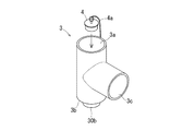
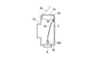
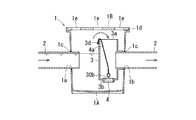
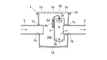
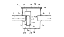
図1は本発明の一実施形態に係る雨水貯溜配管構造を示す概略斜視図、図2は同配管構造の要部を示すものであって、閉塞部材を排出口に取付けた状態の断面図、図3は同配管構造の要部を示すものであって、閉塞部材を排出口から取外した状態の断面図、図4は同配管構造の説明図、図5は同配管構造に用いる本発明の一実施形態に係る堰部材を示す斜視図である。 FIG. 1 is a schematic perspective view showing a rainwater storage piping structure according to an embodiment of the present invention, FIG. 2 is a sectional view showing a main part of the piping structure, and a state in which a closing member is attached to a discharge port, FIG. 3 shows the main part of the piping structure, and is a cross-sectional view of the state where the closing member is removed from the discharge port, FIG. 4 is an explanatory view of the piping structure, and FIG. It is a perspective view which shows the dam member which concerns on one Embodiment.
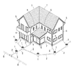
本発明の雨水貯溜配管構造(以下、単に配管構造という。)は、図1に示すように、複数の雨水桝1と雨水桝1を排水管2で接続した宅地内において、最も下流側に位置する雨水桝1に堰部材3を設け、その堰部材3よりも上流側に位置する排水管2の内部及び雨水桝1の内部に雨水を貯溜し、その貯溜した雨水を植物の水やり等に有効利用できるようにすると共に、併せて、集中豪雨時の河川や下水道施設への負荷を低減するようにしたものである。
The rainwater storage piping structure of the present invention (hereinafter simply referred to as piping structure) is located on the most downstream side in a residential land where a plurality of
この配管構造において、家屋に降った雨水は家屋の屋根7を流下して、家屋の屋根7の周囲に設けられた軒樋5に流入し、竪樋6を経由して宅地内に埋設された排水管2から雨水桝1に集水され、最も下流側に位置する雨水桝1に設けられた堰部材3により堰止められて、それよりも上流側の排水管2内部及び雨水桝1内部に貯溜されていく。また、図2に示すように、雨水桝1の蓋体1Bには、多数の浸透孔1eが穿孔されているので、宅地内に降った雨水もその浸透孔1eを通して雨水桝1に流入し、堰部材3により堰止められて貯溜される。勿論、台風などの集中豪雨時には、雨水は堰部材3を越流して、公共の雨水排水本管8を通じて河川や下水道施設に排出されるので、排水管2内部がパンクしてしまう心配はない。
In this piping structure, the rainwater that falls on the house flows down the
宅地内に埋設される雨水桝1は、耐久性や施工性に優れる合成樹脂製(ポリプロピレン製や塩化ビニル樹脂製)の桝であって、図2に示すように、上端が開口し下端が閉口したバケツ型の桝本体1Aと、多数の浸透孔1eが穿孔された蓋体1Bからなる。桝本体1Aの周面には、排水管2が接続される流入口1aと流出口1bがそれぞれ設けられていると共に、桝本体1Aの上端には、断面形状が略凹型の蓋受部1dが外側に向って突設されており、その蓋受部1dに蓋体1Bが載置されている。
The
上記の流入口1aや流出口1bは、ホールソーなどで雨水桝1の周面に孔を穿孔することで設けられており、これら流入口1a、流出口1bの周面には、止水性を向上させる環状のシールパッキン1cが周設されている。このようにして流入口1aや流出口1bを設けると、任意の箇所に流入口1aや流出口1bを設けることが可能となり、配管の自由度が向上するため施工性が良好なものとなり好ましいが、側壁に排水管接続口が一体に形成された雨水桝でも良いことは言うまでもない。
尚、泥砂が多い場所や蚊等の虫の発生が多い場所に雨水桝1を設置する場合は、浸透孔1eが穿孔されていない蓋体1Bを用いてもよいが、上記雨水桝1の開口部全面(雨水桝1の上端や蓋体1Bの裏面、表面など)又は蓋体1Bの浸透孔1eに別途フィルター部材(不図示)を設けると、宅地内に降った雨水を貯溜でき、且つ、蚊等の発生も抑えることができるので好ましい。また、後述するが、本実施形態のように、堰部材3を雨水桝1の流入口1aに設ける場合、複数の浸透孔が内壁面(底面含む)に穿孔された雨水桝を用いると、堰部材3の第一の口3aから雨水桝1に流入した雨水が、桝本体1Aの内部に残らないので、蚊等の虫の発生を抑制できて好ましい。
The
In addition, when installing the
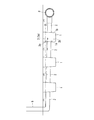
上記雨水桝1の流入口1a及び流出口1bに接続される排水管2は、通常の塩化ビニル樹脂製の円筒形のパイプであって、図4に示すように、上流側から下流側に向けて1/100〜3/100程度の若干の流れ勾配が付けられている。従って、竪樋6或いは雨水桝1の浸透孔1eから流入した雨水は、排水管2の流れ勾配に沿って最も下流側に設置された雨水桝1まで流れるようになっている。
尚、本実施形態のように、必ずしも排水管2に流れ勾配を付ける必要はなく、流れ勾配は無くてもよい。また、この排水管2を、宅地内に埋設される通常の塩化ビニル樹脂製パイプよりも太くすると、貯溜量を増やすことができるのは言うまでもなく、断面楕円形や卵形状の排水管2を使用すると、排出口30bから閉塞部材4を取外して雨水を排出するときの掃流性が向上し、排水管2内部の泥などを排出し易くすることができる。この排水管2は、複数の浸透孔が穿孔された浸透管でもよく、その排水管2を雨水排水本管8にではなく、浸透桝や浸透槽と接続してもよい。このようにすると、雨水の貯溜(利用)と浸透を宅地内で完結させることができ、配管の自由度が向上する。
The
Note that, as in the present embodiment, it is not always necessary to apply a flow gradient to the
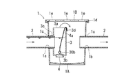
図1、図2に示すように、最も下流側に設置された雨水桝1の流入口1aには、本発明の最大の特徴である堰部材3が設けられている。この堰部材3は、図5に示すように、上方に向けられる第一の口3aと、下方に向けられる第二の口3bと、雨水桝1の流入口1aに接続される第三の口3cとからなるT字形状をした筒状体であって、下方に向けられる第二の口3bは閉口されて、その底面には雨水を堰部材3の外部に排出するための排出口30bが形成されている。第二の口3bに形成された排出口30bは、オリフィスのような小径孔ではなく、貯溜した雨水を速やかに外部に排出することができる程度の直径を有する円孔で、メンテナンス時は、この排出口30bより雨水を排出して配管内部のメンテナンスを行う。通常は、この排出口30bに、脱着可能な閉塞部材4が取付けられて、排出口30bが閉塞されることで第二の口3bは完全に閉塞されている。
尚、本実施形態の堰部材3は、上記のようにT字形状をしているが、排水管2が接続される接続口(第三の口3c)と、雨水が越流する開口(第二の口3b)と、雨水が排出される排出口30bを有するものであればT字形状に限定されるものではなく、例えばL字形状であってもよい。
As shown in FIGS. 1 and 2, a
The
上記第二の口3bの排出口30bに取付けられる閉塞部材4は、水回りの止水栓として好適に使用されるゴム栓であって、図2、図3等に示すように、この閉塞部材4には、上方から閉塞部材4の脱着を可能とするガイド部材4aが備えられている。このガイド部材4aは、止水栓に好適に備えられるボールチェーンであって、その上端は、第一の口3aの外周面に設けられた突起3dに取付けられている。第二の口3bに形成された排出口30bは、第一の口3aに対向する位置、即ち、第一の口3aの開口から見える位置に形成されており、且つ、閉塞部材4にはガイド部材4aが備えられているので、閉塞部材4を取付けたり取外したりする脱着作業を、上方から容易に行うことができ、堰部材3の底面まで手を突っ込む必要がないため、メンテナンス性に優れる。
尚、閉塞部材4は、本実施形態のようにゴム栓に限定されるものではなく、上方から開閉可能な蓋部材などでもよいが、貯溜された雨水によって生じる浮力によって浮き上がらない程度の比重を有するものが好ましく、必要に応じて排水口30bと閉塞部材4との間に嵌合構造や係止構造などを設け、浮力のみで閉塞部材4が排水口30bから外れないようにすることが好ましい。また、ガイド部材4aも、上方から閉塞部材4の脱着を可能とするのであればボールチェーンに限定されるものはなく、線材の折り曲げ加工品等でもよい。更に、本実施形態のガイド部材4aの上端は、第一の口3a近傍に取付けられているが、上方からの脱着が可能な位置、例えば、雨水桝1の蓋受部1d近傍や蓋体1B等に取付けてもよく、このように、ガイド部材4aの上端を、雨水桝1の蓋受部1d近傍や蓋体1B等に取付けると、雨水桝1が深く埋設されている場合であっても、地表に近いところで閉塞部材4の脱着作業が可能となり、閉塞部材4に手が届かなくて特別な工具が必要になるといったこともなく、メンテナンス性が良い。
The closing
The closing
図2等に示すように、上記堰部材3の第三の口3cは、雨水桝1の内部に収容されており、その第三の口3cの内周面に、雨水桝1の流入口1aに接続された上流側の排水管2が挿入されている。従って、排水管2を流れてきた雨水は、雨水桝1に直接流入することなく、堰部材3の内部に流入することになる。上記のように、堰部材3の第二の口3bは閉口しており、排出口30bには閉塞部材4が取付けられているので、排水管2を流れてきた雨水は、堰部材3に堰止められて雨水桝1内部に流入することなく、堰部材3より上流側の排水管2内部及び雨水桝1内部に貯溜されていく。
尚、図示はしないが、堰部材3の第三の口3cを、雨水桝1の流入口1aに挿入して雨水桝1の外側に突出させ、その内周面に上流側の排水管2を挿入してもよい。このようにすると、堰部材3を雨水桝1の内壁面に近づけることができ、雨水桝1内部のメンテナンスが容易となるメリットがある。
As shown in FIG. 2 and the like, the
Although not shown in the figure, the
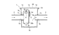
堰部材3より上流側の排水管2及び雨水桝1の内部が満水になった状態で、更に竪樋6等から雨水が排水管2に流入すると、堰部材3の水位が上昇していくことになる。ここで、堰部材3の第一の口3aは開口しているので、上昇してきた雨水は、その開口から溢れ出して雨水桝1の内部に流入し、流出口1bに接続された下流側の排水管2から排出されていく。従って、台風などの集中豪雨時に、雨水が一気に排水管2に流入してきても、排水管2内部が行き場を失った雨水によってパンクしてしまう心配はない。
When the
本発明は、堰部材3の第一の口3a上端(開口)の高さ位置が、雨水の貯溜量を決定する。即ち、第一の口3aは、排水管2より流入した雨水を堰止める役割を果たすものなので、第一の口3a上端の高さ位置を低くすれば、雨水の越流が早く開始されて貯溜量が減少するし、第一の口3a上端の高さ位置を高くすれば、越流が遅く開始されて貯溜量が増加する。従って、雨水を排水管2内部に貯溜するためには、第一の口3a上端の高さ位置が、少なくとも排水管2の管底よりも高い必要があり、排水管2の管頂よりも高いほうが好ましい。上記のように、宅地内に埋設される排水管2には、若干の流れ勾配が付けられていることもあるので、直近の排水管2の管頂(堰部材3の第三の口3cに挿入された排水管2の管頂)より高くても、最も上流側に配管された排水管2の管頂よりも低いと、宅地内に埋設された排水管2内部の全てを貯溜空間とすることはできない。このような事情に鑑みて、本実施形態では、図4に示すように、宅地内に埋設された全ての排水管2内部を貯溜空間とするため、第一の口3a上端の高さ位置が、最も上流側に配管された排水管2の管頂よりも高くなっている。勿論、排水管2に勾配が付けられていない場合は、第一の口3a上端の高さ位置が堰部材3の第三の口3cに挿入された排水管2の管頂よりも高ければ、宅地内に埋設された排水管2内部の全てを貯溜空間とすることができることは言うまでもない。
尚、この第一の口3aは常時開口しているので、雨水が貯溜された状態では、第一の口3aから蚊等の虫が発生する心配もある。そのような虫の発生を抑制するため、この第一の口3aにフィルターや、図6に示す圧力開放弁3eを設けてもよい。この図6に示す圧力開放弁3eは、第一の口3aの内面に内挿されたヒンジ式の開放蓋であって、通常は閉じられていて、排水管2内部の圧力が高まる(水位が上昇する)と開くようになっているものである。このような圧力開放弁3eを設けることで、通常時は排水管2内部と外部の接触が遮断されるため、虫の発生を抑制することができる。この圧力開放弁3eは、本実施形態のように、内挿しではなく、外挿タイプのものでもよく、外挿タイプの圧力開放弁3eは、第一の口3a開口面積が小さくならないというメリットがある。
In the present invention, the height position of the upper end (opening) of the
Since the
尚、上記第一の口3aの高さ調整は、第一の口3aの高さの違う堰部材3を何種類か準備して行ってもよいが、堰部材3の第一の口3aに受け口或いは挿口を形成し、その受け口或いは挿口に、別途筒体を挿入することで調整してもよい。このように別途筒体で、第一の口3aの高さ調整を行うようにすれば、容易に所望の高さに変更することができるし、堰部材3を一種類にすることで製作コストを抑えることもできる。
The height of the
上記のような構成の堰部材3を、最も下流側に設置される雨水桝1の流入口1aに設けると、竪樋6や雨水桝1の浸透孔1eを通して排水管2に流入した雨水は、その流れ勾配に沿って最終の雨水桝1へと流下し、堰部材3によって堰止められて、雨水は直接雨水桝1に流入することなく、堰部材3よりも上流側の排水管2内部及び雨水桝1内部に貯溜されていく。本実施形態の堰部材3は、第一の口3aの上端が、最も上流側に配管された排水管2の管頂よりも高い位置となるように調整されているので、宅地内に埋設された全ての排水管2内部及び雨水桝1内部が貯溜空間となり、植物の水やり等に有効利用するのに十分な量の雨水を貯溜することができる。この貯溜した雨水は、雨水桝1や排水管2の途中経路にポンプなどの取水装置を設けて、そこから取水するようにすれば、容易に貯溜した雨水を有効利用することができるので好ましい。
尚、本実施形態のように、堰部材3を設けた雨水桝1が最も低い位置にある場合は、堰部材3の近傍に取水装置を設けると最も効率よく取水することができる。また、本実施形態とは逆に、排水管2に勾配を付けなければ、宅地内に埋設された配管構造のどこからでも取水することが可能となり、その場合は、取水したい箇所で分岐させて、分岐点から取水箇所に向って下り勾配を付けることで、貯溜空間に貯溜された雨水を効率よく有効利用することができる。
When the
In addition, like this embodiment, when the
一方、メンテナンス時は、貯溜した雨水を排水管2内部から排出して行う。その場合、最終の雨水桝1の蓋体1Bを開けて、第一の口3a近傍の突起3dに取付けられたガイド部材4aを上方に引き上げるという簡易な作業で、排出口30bに取付けられた閉塞部材4を取外すことができるので、貯溜された雨水は、その排出口30bより外部(雨水桝1)に速やかに排出されて、雨水桝1の流出口1bに接続された下流側の排水管2より、公共の雨水排水本管8へと流出していく。
On the other hand, during maintenance, the stored rainwater is discharged from the
このように、本発明の配管構造は、上記構成の堰部材3を最終の雨水桝1の流入口1aに設けるだけで、有効利用するための雨水を貯溜することができ、併せて、集中豪雨時の河川や下水道施設への負荷を低減することができるものである。しかも、従来のような、地面の掘削や配管の変更等の大がかりな土木工事は不要で、最終の雨水桝1の流入口1aに、堰部材3を設けるという簡易な施工で実施することができるので、既設の配管設備にも容易に適用可能で、コストが抑えられると共にメンテナンス性にも優れる。
上記のように、本実施形態では、最終の雨水桝1に堰部材3を設けているが、堰部材3を設ける箇所は、最終の雨水桝1(最も低い雨水桝1)に限定されるものではなく、堰部材3は雨水を貯溜したい領域の最も下流側に設ければよいものである。
As described above, the piping structure of the present invention can store rainwater for effective use only by providing the
As described above, in this embodiment, the
尚、雨水桝1の流入口1aと一体の堰を設けても同様の効果を奏するが、本実施形態の堰部材3のように、雨水桝1と堰部材3を別体にすることで、既設の雨水桝1にも適用可能となるので好ましい。また、貯溜された雨水の排出スピードをより向上させるために、第二の口3bを下窄まりのテーパー面として、空気芯を形成するようにしてもよい。
In addition, although the same effect is produced even if the weir integral with the
図7は本発明の他の実施形態に係る雨水貯溜配管構造の要部を示すものであって、閉塞部材を排出口に取付けた状態の断面図、図8は同配管構造の要部を示すものであって、閉塞部材を排出口から取外した状態の断面図である。 FIG. 7 shows a main part of a rainwater storage piping structure according to another embodiment of the present invention, and is a sectional view showing a state in which a closing member is attached to a discharge port. FIG. 8 shows a main part of the piping structure. FIG. 3 is a cross-sectional view showing a state where the closing member is removed from the discharge port.
図7、図8に示す配管構造は、前述した図1〜図5に示す配管構造が、雨水桝1の流入口1aに堰部材3を設けたものであるのに対して、雨水桝1の流出口1bに堰部材3を設けたものである。この堰部材3は、第三の口3cが雨水桝1の内部の流出口1b近傍に収容されて雨水桝1に設けられていると共に、その第三の口3cの内周面に、下流側の排水管2が挿入されている。
The piping structure shown in FIGS. 7 and 8 is different from the above-described piping structure shown in FIGS. 1 to 5 in that the
このように、雨水桝1の流出口1bに堰部材3を設けると、上流側から流下してきた雨水は、流入口1aに接続された上流側の排水管2より、最終の雨水桝1の内部に流入する。堰部材3を設けていない場合、雨水桝1に流入した雨水は、そのまま流出口1bより下流側の排水管2に流出していくが、流出口1bには堰部材3が設けられているので、流入した雨水は、直ちに下流側に排出されることなく、堰部材3によって堰止められて、堰部材3よりも上流側の雨水桝1内部及び排水管2内部に貯溜されていく。この実施形態の第一の口3aの上端も、前述した実施形態と同様に、最も上流側に配管された排水管2の管頂よりも高い位置にあるので、宅地内に埋設された全ての配管設備の内部に雨水を貯溜することができる。そして、堰部材3よりも上流側の排水管2や雨水桝1が満水になると、水位は更に上昇を始め、第一の口3aから堰部材3の内部に流入し、第三の口3cより下流側の排水管2へと流出していくので、排水管2がパンクしてしまう心配はない。
As described above, when the
一方、メンテナンス時は、閉塞部材4を排出口30bから取外すと、図8の矢印に示す如く、雨水は該排出口30bより堰部材3の内部に流入し、第三の口3cより下流側の排水管2へと流出していくので、貯溜した雨水は速やかに排水管2内部から排出され、直ちにメンテナンスを行うことができる。
本実施形態の配管構造のその他の構成は、前述した図1〜図5に示す配管構造と同様であるので、同一部材に同一符号を附して説明を省略する。
On the other hand, at the time of maintenance, when the closing
Since the other structure of the piping structure of this embodiment is the same as that of the piping structure shown in FIGS. 1-5 mentioned above, the same code | symbol is attached | subjected to the same member and description is abbreviate | omitted.
本実施形態の配管構造も、前述した図1〜図5に示す実施形態の配管構造と同様に、簡易な施工で、植物の水やり等に有効利用するための雨水を貯溜することができ、メンテナンス性にも優れる。 As with the piping structure of the embodiment shown in FIGS. 1 to 5 described above, the piping structure of the present embodiment can store rainwater for effective use for watering plants, etc. with simple construction. Excellent maintainability.
図9は本発明の更に他の実施形態に係る雨水貯溜配管構造の要部を示すものであって、閉塞部材を排出口に取付けた状態の断面図である。 FIG. 9 shows a main part of a rainwater storage piping structure according to still another embodiment of the present invention, and is a cross-sectional view showing a state in which a closing member is attached to a discharge port.
本実施形態の配管構造は、第二の口3bに形成された排出口30bに、図9に示す閉塞部材40を取付けたものである。この閉塞部材40は、その外径が排出口30bの内径に等しい円筒体であって、排出口30bの下端部には、閉塞部材40の下端を載置する筒受段部31bが形成されており、閉塞部材40の下端が排出口30bの筒受段部31bに載置されて立設されている。
In the piping structure of the present embodiment, a closing
堰部材3の排出口30bに上記閉塞部材40を立設すると、排出口30bが閉塞されるので、前述した実施形態と同様に、雨水桝1の流入口1aより流入してきた雨水は、堰部材3よりも上流側の排水管2内部及び雨水桝1内部に貯溜されていく。そして、水位が上昇して、閉塞部材40の上端高さにまで雨水が達すると、雨水は閉塞部材40の上端開口に流入し、排出口30bから排出されるようになっている。このように、本実施形態の配管構造では、規定量を超えた雨水は、第一の口3aからではなく、閉塞部材40を経由して排出口30bより排出されていく。従って、閉塞部材40の上端の高さを調整することで、貯溜量を調整することができるのである。勿論、閉塞部材40の上端が、第一の口3aの上端より高くても不都合は生じないが、閉塞部材40の上端の高さを、第一の口3aの上端よりも低くして、閉塞部材40の上端高さで貯溜量を調整すると、容易に貯溜量を変更できるので好ましい。
When the closing
図9に示すように、上記閉塞部材40の側壁には、オリフィス40bが形成されている。このオリフィス40bは、閉塞部材40側壁の異なる高さに複数形成されており、任意の高さにオリフィス40bを形成することで、想定した貯溜量を超えた雨水は徐々にオリフィス40bより排出されて、雨水の一時的な流出抑制の機能が付与されている。このように、異なる高さに複数のオリフィス40bを形成した場合、使用しないオリフィス40bには栓(不図示)をしておけばよく、複数のオリフィス40bを形成することで、一つのオリフィス40bが詰まったとしても、他のオリフィスで排出の機能を果たすことができるので好ましい。勿論、メンテナンス時には、閉塞部材40を排出口30bから取外して、貯溜した雨水を排出口30bから一気に排出すればよい。
本実施形態の配管構造のその他の構成は、前述した図1〜図7に示す配管構造と同様であるので、同一部材に同一符号を附して説明を省略する。
As shown in FIG. 9, an
Since the other structure of the piping structure of this embodiment is the same as that of the piping structure shown in FIGS. 1-7 mentioned above, the same code | symbol is attached | subjected to the same member and description is abbreviate | omitted.
本実施形態の配管構造も、前述した図1〜図8に示す実施形態と同様の、優れた効果を奏する配管構造を実現することができるのに加えて、閉塞部材40側壁にオリフィス40bを形成することで、雨水の一時的な流出抑制の機能を付与することができる。
The piping structure of the present embodiment can realize a piping structure having excellent effects similar to the embodiment shown in FIGS. 1 to 8 described above, and in addition, an
1 雨水桝
1A 桝本体
1a 流入口
1b 流出口
1c シールパッキン
1d 蓋受部
1B 蓋体
1e 浸透孔
2 排水管
3 堰部材(堰)
3a 第一の口
3b 第二の口
30b 排出口
3c 第三の口
3d 突起
3e 圧力開放弁
4,40 閉塞部材
4a ガイド部材
40b オリフィス
5 軒樋
6 竪樋
7 家屋の屋根
8 雨水排水本管
DESCRIPTION OF
Claims (6)
雨水桝の流入口又は流出口に、上方が開口した堰を設け、
上記堰に排出口を形成すると共に、該排出口に脱着可能な閉塞部材を取付けたことを特徴とする雨水貯溜配管構造。 A rainwater storage piping structure for storing rainwater in a drain pipe connected to a rainwater tank,
A weir with an open top is provided at the inflow or outflow of the rainwater tank,
A rainwater storage piping structure characterized in that a discharge port is formed in the weir and a detachable closing member is attached to the discharge port.
Priority Applications (1)
| Application Number | Priority Date | Filing Date | Title |
|---|---|---|---|
| JP2013067820A JP6034732B2 (en) | 2013-03-28 | 2013-03-28 | Rainwater storage piping structure and weir member used therefor |
Applications Claiming Priority (1)
| Application Number | Priority Date | Filing Date | Title |
|---|---|---|---|
| JP2013067820A JP6034732B2 (en) | 2013-03-28 | 2013-03-28 | Rainwater storage piping structure and weir member used therefor |
Publications (2)
| Publication Number | Publication Date |
|---|---|
| JP2014190098A true JP2014190098A (en) | 2014-10-06 |
| JP6034732B2 JP6034732B2 (en) | 2016-11-30 |
Family
ID=51836635
Family Applications (1)
| Application Number | Title | Priority Date | Filing Date |
|---|---|---|---|
| JP2013067820A Active JP6034732B2 (en) | 2013-03-28 | 2013-03-28 | Rainwater storage piping structure and weir member used therefor |
Country Status (1)
| Country | Link |
|---|---|
| JP (1) | JP6034732B2 (en) |
Cited By (3)
| Publication number | Priority date | Publication date | Assignee | Title |
|---|---|---|---|---|
| JP2016079763A (en) * | 2014-10-22 | 2016-05-16 | タキロン株式会社 | Rainwater storage pipeline structure, and rainwater basin used therewith |
| JP2018187606A (en) * | 2017-05-12 | 2018-11-29 | 株式会社システック | Waste liquid treatment equipment |
| CN117605961A (en) * | 2023-11-10 | 2024-02-27 | 长江水利委员会长江科学院 | A cylindrical overflow pressure regulating tower structure in a long-distance water pipeline |
Citations (8)
| Publication number | Priority date | Publication date | Assignee | Title |
|---|---|---|---|---|
| JPS5998977U (en) * | 1982-12-22 | 1984-07-04 | タキロン株式会社 | Trap drainage basin |
| JPH0336080U (en) * | 1989-08-11 | 1991-04-09 | ||
| JP3104067B2 (en) * | 1989-11-24 | 2000-10-30 | ソニー株式会社 | Semiconductor device manufacturing method |
| JP2002106051A (en) * | 2000-09-27 | 2002-04-10 | Maezawa Kasei Ind Co Ltd | Repair method and repair basin for existing manhole |
| JP2004150077A (en) * | 2002-10-29 | 2004-05-27 | East Japan Railway Trading Co Ltd | Automatic draining type water receiving tank |
| US6796325B1 (en) * | 1999-10-27 | 2004-09-28 | Bryant Group Plc | Apparatus for stormwater retention and release, and method of use thereof |
| JP2006063761A (en) * | 2004-08-30 | 2006-03-09 | Sekisui Chem Co Ltd | Residential rainwater storage system |
| JP2010127020A (en) * | 2008-11-28 | 2010-06-10 | Takiron Co Ltd | Rainwater drain pipe structure |
-
2013
- 2013-03-28 JP JP2013067820A patent/JP6034732B2/en active Active
Patent Citations (8)
| Publication number | Priority date | Publication date | Assignee | Title |
|---|---|---|---|---|
| JPS5998977U (en) * | 1982-12-22 | 1984-07-04 | タキロン株式会社 | Trap drainage basin |
| JPH0336080U (en) * | 1989-08-11 | 1991-04-09 | ||
| JP3104067B2 (en) * | 1989-11-24 | 2000-10-30 | ソニー株式会社 | Semiconductor device manufacturing method |
| US6796325B1 (en) * | 1999-10-27 | 2004-09-28 | Bryant Group Plc | Apparatus for stormwater retention and release, and method of use thereof |
| JP2002106051A (en) * | 2000-09-27 | 2002-04-10 | Maezawa Kasei Ind Co Ltd | Repair method and repair basin for existing manhole |
| JP2004150077A (en) * | 2002-10-29 | 2004-05-27 | East Japan Railway Trading Co Ltd | Automatic draining type water receiving tank |
| JP2006063761A (en) * | 2004-08-30 | 2006-03-09 | Sekisui Chem Co Ltd | Residential rainwater storage system |
| JP2010127020A (en) * | 2008-11-28 | 2010-06-10 | Takiron Co Ltd | Rainwater drain pipe structure |
Cited By (3)
| Publication number | Priority date | Publication date | Assignee | Title |
|---|---|---|---|---|
| JP2016079763A (en) * | 2014-10-22 | 2016-05-16 | タキロン株式会社 | Rainwater storage pipeline structure, and rainwater basin used therewith |
| JP2018187606A (en) * | 2017-05-12 | 2018-11-29 | 株式会社システック | Waste liquid treatment equipment |
| CN117605961A (en) * | 2023-11-10 | 2024-02-27 | 长江水利委员会长江科学院 | A cylindrical overflow pressure regulating tower structure in a long-distance water pipeline |
Also Published As
| Publication number | Publication date |
|---|---|
| JP6034732B2 (en) | 2016-11-30 |
Similar Documents
| Publication | Publication Date | Title |
|---|---|---|
| US6796325B1 (en) | Apparatus for stormwater retention and release, and method of use thereof | |
| KR100846420B1 (en) | Backflow prevention device for manhole of sewer pipe | |
| JP5270316B2 (en) | Rainwater drainage piping structure | |
| JP6013893B2 (en) | Rainwater storage piping structure | |
| KR101064335B1 (en) | Rain gutters with odor barrier | |
| KR20080007089A (en) | Backflow prevention device for manhole of sewer pipe | |
| JP2014015800A (en) | Piping structure for storing rainwater | |
| JP6034732B2 (en) | Rainwater storage piping structure and weir member used therefor | |
| JP2008267023A (en) | Rainwater storage system | |
| CN201284492Y (en) | Simple and practical overhead road rainwater utilization system | |
| JP2011074563A (en) | Rainwater infiltration system | |
| CN217150561U (en) | A rainwater overflow filter cover and overflow well | |
| CN112726659B (en) | Double anti-backflow retaining wall drainage pipe and use method thereof | |
| JP6739887B1 (en) | Secondary drainage method in case of flood damage | |
| JP3888857B2 (en) | Rainwater runoff control facility | |
| JP6153122B2 (en) | Rainwater storage piping structure and drainage basin used therefor | |
| KR100806259B1 (en) | Storm collecting device | |
| KR101433076B1 (en) | System for managing stormwater runoff and underground water | |
| JP3671373B2 (en) | Underground irrigation system | |
| KR100669228B1 (en) | Drainage structure in building complex to prevent rain | |
| JP6391008B2 (en) | Rainwater storage pipe structure and rainwater tank used for it | |
| KR200466978Y1 (en) | Rain water storing apparatus using digging hole | |
| JP5992738B2 (en) | Rainwater storage piping structure | |
| JP6510857B2 (en) | Rainwater drainage system | |
| JP2004036310A (en) | Rainwater treatment system |
Legal Events
| Date | Code | Title | Description |
|---|---|---|---|
| A621 | Written request for application examination |
Free format text: JAPANESE INTERMEDIATE CODE: A621 Effective date: 20151002 |
|
| RD02 | Notification of acceptance of power of attorney |
Free format text: JAPANESE INTERMEDIATE CODE: A7422 Effective date: 20151212 |
|
| A977 | Report on retrieval |
Free format text: JAPANESE INTERMEDIATE CODE: A971007 Effective date: 20160617 |
|
| A131 | Notification of reasons for refusal |
Free format text: JAPANESE INTERMEDIATE CODE: A131 Effective date: 20160621 |
|
| A521 | Request for written amendment filed |
Free format text: JAPANESE INTERMEDIATE CODE: A523 Effective date: 20160805 |
|
| TRDD | Decision of grant or rejection written | ||
| A01 | Written decision to grant a patent or to grant a registration (utility model) |
Free format text: JAPANESE INTERMEDIATE CODE: A01 Effective date: 20161011 |
|
| A61 | First payment of annual fees (during grant procedure) |
Free format text: JAPANESE INTERMEDIATE CODE: A61 Effective date: 20161028 |
|
| R150 | Certificate of patent or registration of utility model |
Ref document number: 6034732 Country of ref document: JP Free format text: JAPANESE INTERMEDIATE CODE: R150 |
|
| S533 | Written request for registration of change of name |
Free format text: JAPANESE INTERMEDIATE CODE: R313533 |
|
| R350 | Written notification of registration of transfer |
Free format text: JAPANESE INTERMEDIATE CODE: R350 |
|
| R250 | Receipt of annual fees |
Free format text: JAPANESE INTERMEDIATE CODE: R250 |
|
| R250 | Receipt of annual fees |
Free format text: JAPANESE INTERMEDIATE CODE: R250 |
|
| R250 | Receipt of annual fees |
Free format text: JAPANESE INTERMEDIATE CODE: R250 |
|
| R250 | Receipt of annual fees |
Free format text: JAPANESE INTERMEDIATE CODE: R250 |
|
| R250 | Receipt of annual fees |
Free format text: JAPANESE INTERMEDIATE CODE: R250 |
|
| R250 | Receipt of annual fees |
Free format text: JAPANESE INTERMEDIATE CODE: R250 |
|
| R250 | Receipt of annual fees |
Free format text: JAPANESE INTERMEDIATE CODE: R250 |