JP2014189285A - Stored object fixing member - Google Patents
Stored object fixing member Download PDFInfo
- Publication number
- JP2014189285A JP2014189285A JP2013064002A JP2013064002A JP2014189285A JP 2014189285 A JP2014189285 A JP 2014189285A JP 2013064002 A JP2013064002 A JP 2013064002A JP 2013064002 A JP2013064002 A JP 2013064002A JP 2014189285 A JP2014189285 A JP 2014189285A
- Authority
- JP
- Japan
- Prior art keywords
- fixing member
- stored
- stored article
- article fixing
- stored object
- Prior art date
- Legal status (The legal status is an assumption and is not a legal conclusion. Google has not performed a legal analysis and makes no representation as to the accuracy of the status listed.)
- Granted
Links
Images


Abstract
Description
本発明は、収納物固定部材に関するものである。特に、衝撃に対して敏感な物品をダンボール箱などに包装するのに用いる収納物固定部材に関するものである。 The present invention relates to a stored article fixing member. In particular, the present invention relates to a stored article fixing member used for packaging articles sensitive to impacts in a cardboard box or the like.
衝撃に対して敏感な物品を包装する場合、従来から緩衝材が使われていて、これらの緩衝材としては、発泡樹脂のペレットや、収納する物品の形状に合わせて成形した発泡樹脂の成形品が用いられている。また、最近では、発泡樹脂の廃棄が問題になり、ダンボール紙などで、物品の形状に合わせて仕切りを兼ねた緩衝材も使用されている。 Conventionally, cushioning materials have been used to package impact-sensitive articles, and these cushioning materials include foamed resin pellets and foamed resin molded products that are molded according to the shape of the goods to be stored. Is used. In addition, recently, disposal of foamed resin has become a problem, and a cushioning material that also serves as a partition according to the shape of the article is used, such as cardboard paper.
成形品やダンボール紙の緩衝材では、物品の形状に合わせて、それぞれ、作らなければならないことや、緩衝効果をより強く求められる、衝撃に対して敏感な物品に対しては、物品を2枚のフィルムの間に挟んで、浮かせた状態で包装することが行われるようになってきた。 For cushioning materials of molded products and cardboard paper, two articles are required for articles that must be made according to the shape of the article, and for articles that are more sensitive to shocks that require a stronger cushioning effect. It has come to be carried out in a state where it is sandwiched between films and floated.
例えば、外箱の内部に装着し収納物を両側から挟むように保持して緩衝性を付与する緩衝材で、板紙又は段ボールを基材として、矩形状の天板とその周囲四辺に折り曲げ線を介して側壁板を連設し、且つ天板の中央には窓状の打ち抜き部を設け、その上に緩衝機能性フィルムを窓貼りして構成し、緩衝機能性フィルム側が収納物に対向するようにして用いる緩衝材がある(例えば、特許文献1)。 For example, it is a cushioning material that is mounted inside the outer box and holds the stored item so as to sandwich it from both sides, and provides cushioning properties. Using a paperboard or cardboard as a base material, a rectangular top plate and its surrounding four sides are bent. A side wall plate is continuously provided, and a window-like punched portion is provided at the center of the top plate, and a buffer functional film is pasted on the window so that the buffer functional film side faces the stored item. There is a buffer material to be used (for example, Patent Document 1).
上記のような緩衝材では、上下2つの緩衝材がセットとなっていて、それぞれにフィルムが貼られている。このような構造の場合、梱包の中で緩衝材が中で動くことがあり、上下の緩衝材が水平に安定しているとは限らず、緩衝材の機能を果たせない恐れがある。 In the cushioning material as described above, the upper and lower cushioning materials are a set, and a film is stuck to each. In the case of such a structure, the cushioning material may move in the package, and the upper and lower cushioning materials are not always stable horizontally, and the function of the cushioning material may not be achieved.
公知文献を以下に示す。 Known documents are shown below.
本発明は上記した事情に鑑みてなされたもので、外箱の中で安定して収納物を固定でき、緩衝効果が損なわれることのない収納物固定部材を提供することを課題としている。 The present invention has been made in view of the above-described circumstances, and an object thereof is to provide a stored item fixing member that can stably fix a stored item in an outer box and that does not impair the buffering effect.
本発明の請求項1に係る発明は、外箱に挿入し収納物を固定する収納物固定部材であって、
折罫を対称軸として上下に対称な一対の収納物固定板と、該一対の収納物固定板の左右にそれぞれ折罫を介し、前記外箱の側面の内側に沿うように保持板を設け、前記収納物固定板には開孔部が設けられ、該開孔部を塞ぐようにフィルムが設けられ、前記対称軸の折罫から折って、対向した前記フィルムの間に前記収納物を固定することを特徴とする収納物固定部材である。
The invention according to
A pair of stored article fixing plates that are symmetrical in the vertical direction with the folding line as the axis of symmetry, and a holding plate is provided along the inner side of the side surface of the outer box via the folding lines on the left and right of the pair of stored article fixing plates, respectively. An opening is provided in the stored article fixing plate, a film is provided so as to close the opening, and the stored article is fixed between the opposed films by folding from the fold of the axis of symmetry. This is a stored article fixing member.
本発明の収納物固定部材は、以上のような構成であって、一対の収納物固定板が折罫を介して設けられ、外箱の側面の内側に沿うように保持板を設けられ、この保持板で収納物
固定板が支えられるので、収納物固定板が安定して、収納物固定板にもう受けられたフィルムに挟まれた収納物は安定して固定され、緩衝効果が損なわれることがない。
The stored article fixing member of the present invention is configured as described above, and a pair of stored article fixing plates are provided via folding lines, and a holding plate is provided along the inside of the side surface of the outer box. Since the holding plate is supported by the holding plate, the holding plate is stable, and the holding object sandwiched between the films already received by the holding plate is stably fixed, and the buffering effect is impaired. There is no.
また、本収納物固定部材では、縦置きが可能であるので、床面積が少なく済むように置くことが出来、包装した後の保管や輸送に便利である。 In addition, since the stored article fixing member can be placed vertically, it can be placed so that the floor area can be reduced, which is convenient for storage and transportation after packaging.
本発明の請求項2に係る発明は、前記一対の収納物固定板の各開孔部を、1枚の前記フィルムが塞ぐように設けられていることを特徴とする請求項1に記載の収納物固定部材である。
The invention according to claim 2 of the present invention is the storage according to
本発明の収納物固定部材は、一対の収納物固定板の各開孔部を、1枚の前記フィルムが塞ぐように設けられているので、フィルムを貼る工程が1回で済み、生産時間の短縮ができ、また、コスト的にも有利である。 Since the stored article fixing member of the present invention is provided so that each of the apertures of the pair of stored article fixing plates is closed by one piece of the film, the process of attaching the film is only once, and the production time is reduced. It can be shortened and is advantageous in terms of cost.
本発明の請求項3に係る発明は、前記収納物固定板の端部に折罫を介し、取っ手を設けたことを特徴とする請求項1または2に記載の収納物固定部材である。
The invention according to claim 3 of the present invention is the stored item fixing member according to
本発明では、収納物固定板の端部に折罫を介し、取っ手を設けてあるので、外箱への出し入れや、外箱に入れる前や、外箱から出したときにも取り扱いが便利で、重量のある収納物であっても片手での取り扱いが可能である。 In the present invention, since a handle is provided at the end of the stored article fixing plate via a crease, handling is convenient even when it is put in and out of the outer box, before it is put in the outer box, and when it is taken out from the outer box. Even heavy items can be handled with one hand.
本発明の収納物固定部材は、外箱の中で安定して収納物を固定でき、緩衝効果が損なわれることがない。 The stored item fixing member of the present invention can stably fix the stored item in the outer box, and the buffering effect is not impaired.
以下、本発明を実施するための形態につき説明する。
図1は、本発明の収納物固定部材の一例の展開図である。
Hereinafter, embodiments for carrying out the present invention will be described.
FIG. 1 is a developed view of an example of the stored article fixing member of the present invention.
本例の収納物固定部材100は、図1の展開図に示すように、折罫aを対称軸として上下に対称な一対の収納物固定板1A、1Bが設けられている。そして、一対の収納物固定板の左右にそれぞれ折罫b、c、d、eを介し、保持板2A、2B、2C、2Dが設けられている。
As shown in the developed view of FIG. 1, the stored
本例では、保持板2B、2Dの右側に折罫f、gを介して補強板3A、3Bが設けられている。また、収納物固定板1Aの上端部に折罫hを介し取っ手4Aが、収納物固定板1Bの下端部に折罫iを介し、取っ手4Bが設けられている。取っ手4A、4Bにはそれぞれ貫通孔5A、5Bが設けられ、折罫aで折ったときに、この貫通孔5A、5Bが重なり、指を差し込んで、取っ手4A、4Bをまとめて持てるようになっている。
In this example, reinforcing
収納物固定板1A、1Bには、それぞれ、開孔部6A、6Bが設けられていて、この開孔部6A、6Bを塞ぐように、1枚のフィルム7が貼られて設けられている。収納物固定板1A、1Bを折罫aで谷折することによって、折られたフィルム7が対向し、その間に収納物を挟み込んで固定するようになっている。
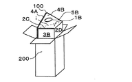
図2は、本発明の収納物固定部材の一例の使用方法を説明する説明図である。
図3は、本発明の収納物固定部材の一例に収納物を収納した状態を説明する説明図で、(A)平面図、(B)正面図である。
FIG. 2 is an explanatory view for explaining a method of using an example of the stored article fixing member of the present invention.
FIGS. 3A and 3B are explanatory views for explaining a state in which the stored items are stored in an example of the stored item fixing member of the present invention, and are (A) a plan view and (B) a front view.
図1の展開図の収納物固定部材100の折罫bを山折し、保持板2Aを図1の背後側に倒し、次に折罫cを山折りし、保持板2Bを背後側に倒す。続いて、折罫fを山折りして、保持板2Aに補強板3Aを重ねる。
The folding line b of the stored
同様に、折罫dを山折し、保持板2Cを図1の背後側に倒し、次に折罫eを山折りし、保持板2Dを背後側に倒す。続いて、折罫gを山折りして、保持板2Cに補強板3Bを重ねる。このとき、保持板2Aと補強板3Aを、また、保持板2Cと補強板3Bを、接着剤で貼って固定してもよいし、また、別の係止機構を設けて固定するようにしてもよい。
Similarly, the crease d is folded in a mountain, the
このようにすると、収納物固定部材100の断面が略三角柱形状になる。そして、図2の説明図のように、収納物固定板1Bの開孔部6Bを覆う部分のフィルム7上に収納物8を置く。
In this way, the cross section of the stored
次に、折罫aを谷折して、収納物8を折られたフィルム7の間に挟んで固定する。このように、折罫aを谷折すると、収納物固定部材100の略三角柱形状が重ねあわされて、断面が略四角柱形状になる。そして、折罫hと折罫iを山折して、取っ手4A、4Bを外側に倒すと、図3の(A)平面図、(B)正面図のようになる。
Next, the crease a is folded, and the
図4は、本発明の収納物固定部材の一例を挿入する外箱を説明する斜視図である。
図5は、本発明の収納物固定部材の一例を外箱に挿入した状態を説明する平面図である。
FIG. 4 is a perspective view illustrating an outer box into which an example of the stored article fixing member of the present invention is inserted.
FIG. 5 is a plan view for explaining a state in which an example of the stored article fixing member of the present invention is inserted into the outer box.
本例の収納物固定部材100を挿入する外箱200は、図4のようなダンボール箱である。この外箱200の上端の開放端より、図3の略四角柱形状になった、収納物固定部材100を挿入する。
The
このようにすると図5の平面図のように、略四角柱形状の収納物固定部材100が断面が四角形の外箱200の中に納まり、外箱200の隣り合う2つの側面の内側に保持板2A、2Bが、外箱200の他の隣り合う2つの側面の内側に保持板2C、2Dが、沿うようになる。
In this way, as shown in the plan view of FIG. 5, the substantially square prism-shaped stored
このため、外箱200の中で、保持板2A、2B、2C、2Dが固定され、その結果、収納物固定板1A、1Bが固定され、外箱200の中で安定して収納物8を固定でき、緩衝効果が損なわれることがない。また、本収納物固定部材100は、縦置きが可能であるので、床面積が少なく済むように置くことが出来、包装した後の保管や輸送にも便利である。
For this reason, the holding
図6は、本発明の収納物固定部材の一例を外箱から取り出す状態を説明する斜視図である。 FIG. 6 is a perspective view for explaining a state in which an example of the stored article fixing member of the present invention is taken out from the outer box.
外箱200から収納物8が固定され保持された収納物固定部材100を取り出すには、図6のように、折られていた折罫h、iを戻して取っ手4A、4Bを、それぞれ収納物固
定板1A、1Bと同一平面になるように起こす。
In order to take out the stored
こうすることによって、重なり合った貫通孔5A、5Bに指を入れて、取っ手4A、4Bを持つことが出来、収納物固定部材100を外箱200から容易に取り出すことが出来る。
By doing so, the fingers can be put into the overlapping through
また、外箱200から取り出すときのみでなく、外箱200へ入れるときにも使用すると便利である。又、外箱200に入れる前や、外箱200から出した後も取り扱いが便利である。そして、重量のある収納物8であっても片手で取り扱うことが可能である。
Moreover, it is convenient to use it not only when taking out from the
収納物固定部材100は、紙とフィルム7からなっている。使用する紙としては、板紙やダンボール紙が好ましく使用することが出来る。又、フィルム7には、ある程度弾性のある樹脂などのフィルムが用いられる。
The stored
フィルムの材料としては、ポリウレタン系熱可塑性エラストマー、エチレン−酢酸ビニル共重合体、シングルサイト触媒で重合した直鎖状低密度ポリエチレンなどのポリオレフィン、天然ゴムや合成ゴムなどが使用することが出来る。特に、ポリウレタン系熱可塑性エラストマーが好ましく使用することが出来る。 As the material for the film, polyurethane thermoplastic elastomer, ethylene-vinyl acetate copolymer, polyolefin such as linear low density polyethylene polymerized with a single site catalyst, natural rubber, synthetic rubber, and the like can be used. In particular, a polyurethane-based thermoplastic elastomer can be preferably used.
上記の板紙やダンボール紙などの紙を打ち抜いて、図1の収納物固定部材100の外形、貫通孔5A、5B、及び、開孔部6A、6Bを形成する。次に、開孔部6A、6Bを塞ぐように、収納物固定板1A、1Bにフィルム7を紙器製造の窓貼りの要領で貼れば、図1の収納物固定部材100が出来上がる。
Paper such as paperboard or cardboard is punched out to form the outer shape, the through
このように、収納物固定部材100は、紙を打ち抜いて、フィルム7を貼るだけであるので製造工程が簡単である。また、収納物固定板1A、1Bが折罫aを介して連続しているので、フィルム7は1枚のフィルムを貼るだけよいので、工程数が少なくてでき、更に、1つの外箱200に1つの収納物固定部材100で済むので、梱包作業も容易でわずらわしさもない。
Thus, since the stored
100・・・収納物固定部材
200・・・外箱
a、b、c、d、e、f、g、h、i・・・折罫
1A、1B・・・収納物固定板
2A、2B、2C、2D・・・保持板
3A、3B・・・補強板
4A、4B・・・取っ手
5A、5B・・・貫通孔
6A、6B・・・開孔部
7・・・フィルム
8・・・収納物
100 ... stored
Claims (3)
折罫を対称軸として上下に対称な一対の収納物固定板と、該一対の収納物固定板の左右にそれぞれ折罫を介し、前記外箱の側面の内側に沿うように保持板を設け、前記収納物固定板には開孔部が設けられ、該開孔部を塞ぐようにフィルムが設けられ、前記対称軸の折罫から折って、対向した前記フィルムの間に前記収納物を固定することを特徴とする収納物固定部材。 A stored article fixing member that is inserted into an outer box and fixes a stored article,
A pair of stored article fixing plates that are symmetrical in the vertical direction with the folding line as the axis of symmetry, and a holding plate is provided along the inner side of the side surface of the outer box via the folding lines on the left and right of the pair of stored article fixing plates, respectively. An opening is provided in the stored article fixing plate, a film is provided so as to close the opening, and the stored article is fixed between the opposed films by folding from the fold of the axis of symmetry. An article fixing member characterized by that.
Priority Applications (1)
| Application Number | Priority Date | Filing Date | Title |
|---|---|---|---|
| JP2013064002A JP6212896B2 (en) | 2013-03-26 | 2013-03-26 | Items fixed |
Applications Claiming Priority (1)
| Application Number | Priority Date | Filing Date | Title |
|---|---|---|---|
| JP2013064002A JP6212896B2 (en) | 2013-03-26 | 2013-03-26 | Items fixed |
Publications (2)
| Publication Number | Publication Date |
|---|---|
| JP2014189285A true JP2014189285A (en) | 2014-10-06 |
| JP6212896B2 JP6212896B2 (en) | 2017-10-18 |
Family
ID=51835954
Family Applications (1)
| Application Number | Title | Priority Date | Filing Date |
|---|---|---|---|
| JP2013064002A Active JP6212896B2 (en) | 2013-03-26 | 2013-03-26 | Items fixed |
Country Status (1)
| Country | Link |
|---|---|
| JP (1) | JP6212896B2 (en) |
Cited By (1)
| Publication number | Priority date | Publication date | Assignee | Title |
|---|---|---|---|---|
| CN108045693A (en) * | 2018-01-16 | 2018-05-18 | 厦门艾美森新材料科技股份有限公司 | A kind of hanging packaging and display box |
Citations (8)
| Publication number | Priority date | Publication date | Assignee | Title |
|---|---|---|---|---|
| GB2264289A (en) * | 1992-01-21 | 1993-08-25 | Peter Charles Dudley Hamilton | Packaging element |
| JPH07330034A (en) * | 1994-06-07 | 1995-12-19 | Nippon Furuuto Kk | Packing apparatus |
| JP3020114U (en) * | 1995-06-30 | 1996-01-19 | 朝日印刷紙器株式会社 | Container using film |
| JPH10119957A (en) * | 1996-08-26 | 1998-05-12 | Kawakami Sangyo Kk | Packaging box |
| JP2003011959A (en) * | 2001-06-26 | 2003-01-15 | Kawakami Sangyo Co Ltd | Packaging box |
| JP2004051163A (en) * | 2002-07-19 | 2004-02-19 | Dainippon Printing Co Ltd | Container with buffer mechanism |
| US20040108239A1 (en) * | 2000-07-31 | 2004-06-10 | Mcdonald John | Suspension packaging assembly |
| JP2004182313A (en) * | 2002-12-05 | 2004-07-02 | Hirotoshi Kosugi | Holder and packaging container using it |
-
2013
- 2013-03-26 JP JP2013064002A patent/JP6212896B2/en active Active
Patent Citations (8)
| Publication number | Priority date | Publication date | Assignee | Title |
|---|---|---|---|---|
| GB2264289A (en) * | 1992-01-21 | 1993-08-25 | Peter Charles Dudley Hamilton | Packaging element |
| JPH07330034A (en) * | 1994-06-07 | 1995-12-19 | Nippon Furuuto Kk | Packing apparatus |
| JP3020114U (en) * | 1995-06-30 | 1996-01-19 | 朝日印刷紙器株式会社 | Container using film |
| JPH10119957A (en) * | 1996-08-26 | 1998-05-12 | Kawakami Sangyo Kk | Packaging box |
| US20040108239A1 (en) * | 2000-07-31 | 2004-06-10 | Mcdonald John | Suspension packaging assembly |
| JP2003011959A (en) * | 2001-06-26 | 2003-01-15 | Kawakami Sangyo Co Ltd | Packaging box |
| JP2004051163A (en) * | 2002-07-19 | 2004-02-19 | Dainippon Printing Co Ltd | Container with buffer mechanism |
| JP2004182313A (en) * | 2002-12-05 | 2004-07-02 | Hirotoshi Kosugi | Holder and packaging container using it |
Cited By (1)
| Publication number | Priority date | Publication date | Assignee | Title |
|---|---|---|---|---|
| CN108045693A (en) * | 2018-01-16 | 2018-05-18 | 厦门艾美森新材料科技股份有限公司 | A kind of hanging packaging and display box |
Also Published As
| Publication number | Publication date |
|---|---|
| JP6212896B2 (en) | 2017-10-18 |
Similar Documents
| Publication | Publication Date | Title |
|---|---|---|
| JP2015078008A (en) | Electronic apparatus package | |
| JP5099149B2 (en) | Packing container | |
| CN103946118A (en) | System and method for bag delivery | |
| US10035638B1 (en) | Retention package with article-loading aperture and method of making and using the same | |
| JP6212896B2 (en) | Items fixed | |
| JP2007076693A (en) | Packing box | |
| JP4043580B2 (en) | Shock absorbing packaging | |
| JP4043579B2 (en) | Shock absorbing packaging | |
| JP6264564B2 (en) | Packaging box | |
| JP5146115B2 (en) | Double-sided article holding plate and package using the same | |
| JP2012229045A (en) | Cover for article holder | |
| JP3233434U (en) | Packaging material | |
| JP5534897B2 (en) | Small precision instrument return box and small precision instrument package | |
| JP3832141B2 (en) | Packaging box | |
| KR101702617B1 (en) | Carrier bag and method for manufacturing carrier bag | |
| JPH07125773A (en) | Simple and easy packing device | |
| KR102618059B1 (en) | Packaging case for square item | |
| JP2009107631A (en) | Capacity-variable packaging box and cardboard for forming packaging box | |
| JP4632511B2 (en) | Cylindrical packing container and packing method | |
| JP6036505B2 (en) | Packaging box for goods transportation | |
| JP2006264782A (en) | Cushioning packaging material for packing | |
| JP3197405U (en) | Buffer holding container | |
| JP2010095302A (en) | Packaging bag | |
| JP2011116402A (en) | Packaging case | |
| JP3100669U (en) | Reuse type buffer support |
Legal Events
| Date | Code | Title | Description |
|---|---|---|---|
| A621 | Written request for application examination |
Free format text: JAPANESE INTERMEDIATE CODE: A621 Effective date: 20160219 |
|
| A977 | Report on retrieval |
Free format text: JAPANESE INTERMEDIATE CODE: A971007 Effective date: 20170119 |
|
| A131 | Notification of reasons for refusal |
Free format text: JAPANESE INTERMEDIATE CODE: A131 Effective date: 20170131 |
|
| A521 | Request for written amendment filed |
Free format text: JAPANESE INTERMEDIATE CODE: A523 Effective date: 20170329 |
|
| TRDD | Decision of grant or rejection written | ||
| A01 | Written decision to grant a patent or to grant a registration (utility model) |
Free format text: JAPANESE INTERMEDIATE CODE: A01 Effective date: 20170822 |
|
| A61 | First payment of annual fees (during grant procedure) |
Free format text: JAPANESE INTERMEDIATE CODE: A61 Effective date: 20170904 |
|
| R150 | Certificate of patent or registration of utility model |
Ref document number: 6212896 Country of ref document: JP Free format text: JAPANESE INTERMEDIATE CODE: R150 |
|
| R250 | Receipt of annual fees |
Free format text: JAPANESE INTERMEDIATE CODE: R250 |
|
| R250 | Receipt of annual fees |
Free format text: JAPANESE INTERMEDIATE CODE: R250 |
|
| R250 | Receipt of annual fees |
Free format text: JAPANESE INTERMEDIATE CODE: R250 |