JP2014184548A - Vibration control device - Google Patents
Vibration control device Download PDFInfo
- Publication number
- JP2014184548A JP2014184548A JP2013251463A JP2013251463A JP2014184548A JP 2014184548 A JP2014184548 A JP 2014184548A JP 2013251463 A JP2013251463 A JP 2013251463A JP 2013251463 A JP2013251463 A JP 2013251463A JP 2014184548 A JP2014184548 A JP 2014184548A
- Authority
- JP
- Japan
- Prior art keywords
- control
- control circuit
- ram
- actuator
- circuit unit
- Prior art date
- Legal status (The legal status is an assumption and is not a legal conclusion. Google has not performed a legal analysis and makes no representation as to the accuracy of the status listed.)
- Granted
Links
Images


Abstract
Description
本発明は、構造物の振動を減衰させる制振装置(ダイナミックダンパ)に関する。 The present invention relates to a vibration damping device (dynamic damper) that attenuates vibration of a structure.
門形加工機は、左右の各々に立設されるコラムと、それらのコラムの間に架け渡されるクロスレールと、クロスレールに設けられるサドルとを備えている。サドルには、ラムが上下動可能に設けられる。ラムの下端部には、旋盤などの工具が取り付けられる。このラムを上下動させながら、左右のコラムの間に設けられるテーブル上のワークを工具により加工する。
ここで、ワークを加工するときの反力により加工機の構成部材に振動が生じる。その振動が加工品位に影響を与えるのを避けるため、加工機には、振動を抑制するための制振装置が設けられる(例えば、特許文献1)。
特許文献1の制振装置は、振動が生じる構造物に対して磁気により離して支持されるウェイトと、構造物の振動を検知する手段とを備えている。この能動(アクティブ)型の制振装置は、磁界を制御することにより、検知された構造物の振動の方向と一致する方向にウェイトを変位させることで構造物に逆位相の外力を加える。これによって構造物の振動が抑制される。
The portal machine includes a column erected on each of the left and right sides, a cross rail that spans between the columns, and a saddle that is provided on the cross rail. The saddle is provided with a ram that can move up and down. A tool such as a lathe is attached to the lower end of the ram. While moving the ram up and down, the workpiece on the table provided between the left and right columns is machined with a tool.
Here, vibration is generated in the constituent members of the processing machine due to the reaction force when processing the workpiece. In order to avoid the vibration from affecting the processing quality, the processing machine is provided with a damping device for suppressing the vibration (for example, Patent Document 1).
The vibration damping device of
加工機のラムは、上下動に伴ってサドルの下方に突き出す量が伸縮する。その突き出し量が大きいと、突き出し量が小さいときよりも動剛性が低下してしまう。ラムの突き出し量によらずに加工品位を確保するため、突き出し量が大きいときの振動を低減する必要がある。
能動型の制振を効果的に行うには、工具が取り付けられるラムの先端にウェイトを設けるとともに、そのウェイトをラムの固有振動数で加振し、ウェイトの振動する慣性力によってラムの振動を打ち消す。
ここで、ラムの固有振動数は突き出し量に応じて変わる。そのため、突き出し量が大きいときの低い固有振動数に合わせて加振すると、その他の突き出し量のときには十分な制振効果が得られないというジレンマがある。
As the ram of the processing machine moves up and down, the amount protruding below the saddle expands and contracts. When the protruding amount is large, the dynamic rigidity is lower than when the protruding amount is small. In order to ensure the processing quality regardless of the ram protrusion amount, it is necessary to reduce vibration when the protrusion amount is large.
In order to effectively perform active vibration suppression, a weight is provided at the tip of the ram to which the tool is attached, the weight is vibrated at the natural frequency of the ram, and the vibration of the ram is affected by the inertial force of the weight. Counteract.
Here, the natural frequency of the ram varies depending on the amount of protrusion. Therefore, there is a dilemma that if the vibration is applied in accordance with the low natural frequency when the protrusion amount is large, a sufficient vibration damping effect cannot be obtained at other protrusion amounts.
また、ラムは、固有振動を励振するほか、工具がワークを周期的に打撃することで強制振動を生じるので、ラムの固有振動を減衰させることができたとしても、強制振動により加工品位が低下するおそれがある。
本発明は、以上のような課題を解決することを目的とする。
In addition to exciting natural vibrations, the rams generate forced vibrations when the tool periodically strikes the workpiece. Therefore, even if the natural vibrations of the rams can be attenuated, the machining quality is reduced by the forced vibrations. There is a risk.
The object of the present invention is to solve the above-described problems.
本発明の制振装置は、加工機の主軸を保持する主軸保持部材に設けられるウェイトと、ウェイトを振動変位させるアクチュエータと、主軸保持部材とウェイトとの相対変位を計測する変位計と、アクチュエータを駆動制御するための制御信号を演算する制御回路部と、制御回路部により演算された制御信号に基づく電流をアクチュエータに供給する駆動部と、を備える。
そして、本発明は、制御回路部が、主軸保持部材の位置に対応する主軸保持部材の固有振動数に応じて制御定数を設定する制御定数設定部と、制御定数および相対変位に基づいて、制御信号のゲインおよび位相を設定する演算部と、を備えることを特徴とする。
The vibration damping device of the present invention includes a weight provided on a spindle holding member that holds a spindle of a processing machine, an actuator that vibrates and displaces the weight, a displacement meter that measures relative displacement between the spindle holding member and the weight, and an actuator. A control circuit unit that calculates a control signal for drive control, and a drive unit that supplies a current based on the control signal calculated by the control circuit unit to the actuator.
In the present invention, the control circuit unit controls the control constant based on the control constant and the relative displacement, the control constant setting unit that sets the control constant according to the natural frequency of the main shaft holding member corresponding to the position of the main shaft holding member. And an arithmetic unit for setting the gain and phase of the signal.
本発明の第1の制振装置では、主軸保持部材とウェイトとの相対変位を変位計で計測しながら、制御回路部および駆動部を動作させてウェイトを振動させることにより、ワークの加工時に主軸保持部材に生じる固有振動を減衰させる。
制御回路部の各部は、次のように動作する。制御定数設定部は、主軸保持部材の位置に対応する主軸保持部材の固有振動数を取得し、その固有振動数に応じて制御定数を設定する。演算部は、制御定数および相対変位に基づいて、固有振動を減衰させるのに必要なゲインおよび位相を設定する。
本発明によれば、加工中の主軸保持部材の位置に対応する固有振動数に応じて適切に設定された制御定数を制御に用いることにより、主軸保持部材のストロークの全体に亘り、十分な制振効果を得ることができる。
In the first vibration damping device of the present invention, the spindle is moved during machining of the workpiece by operating the control circuit unit and the drive unit to vibrate the weight while measuring the relative displacement between the spindle holding member and the weight with a displacement meter. The natural vibration generated in the holding member is attenuated.
Each unit of the control circuit unit operates as follows. The control constant setting unit acquires the natural frequency of the main shaft holding member corresponding to the position of the main shaft holding member, and sets the control constant according to the natural frequency. The calculation unit sets a gain and a phase necessary for attenuating the natural vibration based on the control constant and the relative displacement.
According to the present invention, the control constant appropriately set according to the natural frequency corresponding to the position of the spindle holding member being processed is used for control, so that sufficient control over the entire stroke of the spindle holding member is achieved. A vibration effect can be obtained.
本発明の第2の制振装置は、加工機の主軸を保持する主軸保持部材に設けられるウェイトと、ウェイトを振動変位させるアクチュエータと、主軸保持部材とウェイトとの相対変位を計測する変位計と、アクチュエータを駆動制御するための制御信号を演算する制御回路部と、制御回路部により演算された制御信号に基づく電流をアクチュエータに供給する駆動部と、を備える。
そして、本発明は、制御回路部が、ワークに対して工具が周期的に打撃することで主軸保持部材に生じる強制振動の周波数に応じて制御定数を設定する制御定数設定部と、制御定数および相対変位に基づいて、制御信号のゲインおよび位相を設定する演算部と、を備えることを特徴とする。
A second vibration damping device of the present invention includes a weight provided on a spindle holding member that holds a spindle of a processing machine, an actuator that vibrates and displaces the weight, and a displacement meter that measures relative displacement between the spindle holding member and the weight. A control circuit unit that calculates a control signal for driving and controlling the actuator, and a drive unit that supplies current to the actuator based on the control signal calculated by the control circuit unit.
And this invention, the control circuit part sets a control constant according to the frequency of the forced vibration generated in the spindle holding member by periodically hitting the tool against the work, a control constant and An arithmetic unit configured to set a gain and a phase of the control signal based on the relative displacement.
本発明では、主軸保持部材とウェイトとの相対変位を変位計で計測しながら、制御回路部および駆動部を動作させてウェイトを振動させることにより、ワークの加工時に主軸保持部材に生じる強制振動を減衰させる。
制御回路部の各部は、次のように動作する。制御定数設定部は、主軸保持部材に生じる強制振動の周波数を取得し、その周波数に応じて制御定数を設定する。演算部は、制御定数および相対変位に基づいて、強制振動を減衰させるのに必要なゲインおよび位相を設定する。
本発明によれば、加工中、主軸保持部材に生じる強制振動の周波数に応じて適切に設定された制御定数を制御に用いることにより、強制振動が加工品位に与える影響を排除することができる。
In the present invention, while measuring the relative displacement between the spindle holding member and the weight with a displacement meter, the control circuit unit and the drive unit are operated to vibrate the weight, thereby preventing forced vibration generated in the spindle holding member during workpiece processing. Attenuate.
Each unit of the control circuit unit operates as follows. The control constant setting unit acquires the frequency of forced vibration generated in the spindle holding member and sets the control constant according to the frequency. The calculation unit sets a gain and a phase necessary to attenuate the forced vibration based on the control constant and the relative displacement.
According to the present invention, by using a control constant appropriately set according to the frequency of forced vibration generated in the spindle holding member during processing, it is possible to eliminate the influence of forced vibration on the machining quality.
第2の制振装置において、主軸保持部材の加速度を計測する加速度計と、加速度を用いて、主軸保持部材に生じている振動の複数の周波数成分を取得する周波数成分取得装置と、を備え、制御定数設定部は、複数の周波数成分のうちの強制振動の周波数成分に応じて制御定数を設定することが好ましい。
本発明では、ワークの加工中、加速度を用いて、逐次、強制振動の周波数成分を取得し、それに基づく制御定数を設定して制御することができる。そのため、工具の回転数を変更したり、刃数の異なる工具に交換することで強制振動の周波数が変わっても、適切な制御定数を設定し、回転数変更や工具交換の前後に亘り、継続して強制振動を減衰させることができる。
The second vibration damping device includes an accelerometer that measures the acceleration of the main shaft holding member, and a frequency component acquisition device that uses the acceleration to acquire a plurality of frequency components of vibration generated in the main shaft holding member, The control constant setting unit preferably sets the control constant according to the frequency component of forced vibration among the plurality of frequency components.
In the present invention, during machining of a workpiece, the frequency component of forced vibration can be acquired sequentially using acceleration, and a control constant based on the frequency component can be set and controlled. Therefore, even if the frequency of forced vibration changes by changing the number of rotations of the tool or changing to a tool with a different number of blades, an appropriate control constant is set to continue before and after changing the number of rotations and changing the tool. Thus, the forced vibration can be attenuated.
本発明の第1の制振装置および第2の制振装置において、演算部は、変位計により計測される相対変位、および制御定数に基づいてゲインを設定するゲイン設定部と、制御定数に対応する周波数を設定するとともに、主軸保持部材の振動位相に対して位相を逆転させる位相シフト部と、を備えるように構成することができる。
また、本発明の第1の制振装置および第2の制振装置において、演算部は、変位計により計測される相対変位、および制御定数に基づいてゲインを設定するゲイン設定部と、相対変位に対して位相を進ませる位相補償部と、を備えるように構成することができる。
In the first damping device and the second damping device of the present invention, the calculation unit corresponds to a control unit and a gain setting unit that sets a gain based on a relative displacement measured by a displacement meter and a control constant. And a phase shift unit that reverses the phase with respect to the vibration phase of the main shaft holding member.
In the first damping device and the second damping device of the present invention, the calculation unit includes a relative setting measured by a displacement meter, a gain setting unit that sets a gain based on a control constant, and a relative displacement. And a phase compensator for advancing the phase relative to.
本発明の第1の制振装置および第2の制振装置において、アクチュエータには、いずれも主軸に直交するx方向およびy方向のうちx方向にウェイトを振動変位させるx方向アクチュエータと、y方向にウェイトを振動変位させるy方向アクチュエータとがあり、制御回路部として、x方向アクチュエータを駆動制御するためのx方向制御回路部と、y方向アクチュエータを駆動制御するためのy方向制御回路部とが個別に構成され、駆動部として、x方向アクチュエータに電流を供給するx方向駆動部と、y方向アクチュエータに電流を供給するy方向駆動部とが個別に構成されることが好ましい。 In the first damping device and the second damping device of the present invention, the actuator includes an x-direction actuator that vibrates and displaces the weight in the x-direction among the x-direction and the y-direction orthogonal to the main axis, and the y-direction. There is a y-direction actuator that vibrates and displaces the weight, and the control circuit unit includes an x-direction control circuit unit for driving and controlling the x-direction actuator and a y-direction control circuit unit for driving and controlling the y-direction actuator. It is preferable that the x-direction drive unit that supplies current to the x-direction actuator and the y-direction drive unit that supplies current to the y-direction actuator are individually configured as drive units.
そうすると、主軸に直交するx方向およびy方向の各々について、アクチュエータ、制御回路部、および駆動部が個別に形成されているので、主軸保持部材のx方向およびy方向の各々の振動特性に応じた適切な制振制御が可能となる。 Then, since the actuator, the control circuit unit, and the driving unit are individually formed for each of the x direction and the y direction orthogonal to the main shaft, the vibration characteristics of the main shaft holding member according to each of the x direction and the y direction are determined. Appropriate vibration suppression control is possible.
本発明の第3の制振装置は、加工機の主軸を保持する主軸保持部材に設けられるウェイトと、ウェイトを振動変位させるアクチュエータと、主軸保持部材とウェイトとの相対変位を計測する変位計と、アクチュエータを駆動制御するための第1制御信号を演算する第1制御回路部と、アクチュエータを駆動制御するための第2制御信号を演算する第2制御回路部と、第1制御回路部により演算された第1制御信号に基づく電流と、第2制御回路部により演算された第2制御信号に基づく電流とをアクチュエータに供給する駆動部と、を備える。
そして、本発明は、第1制御回路部が、主軸保持部材の位置に対応する主軸保持部材の固有振動数に応じて第1制御定数を設定する第1制御定数設定部と、第1制御定数および相対変位に基づいて、第1制御信号のゲインおよび位相を設定する第1演算部と、を備え、第2制御回路部が、ワークに対して工具が周期的に打撃することで主軸保持部材に生じる強制振動の周波数に応じて第2制御定数を設定する第2制御定数設定部と、第2制御定数および変相対変位に基づいて、第2制御信号のゲインおよび位相を設定する第2演算部と、を備えることを特徴とする。
A third vibration damping device of the present invention includes a weight provided on a spindle holding member that holds a spindle of a processing machine, an actuator that vibrates and displaces the weight, and a displacement meter that measures relative displacement between the spindle holding member and the weight. The first control circuit unit that calculates the first control signal for driving and controlling the actuator, the second control circuit unit that calculates the second control signal for driving and controlling the actuator, and the first control circuit unit And a drive unit that supplies the actuator with a current based on the first control signal and a current based on the second control signal calculated by the second control circuit unit.
According to the present invention, the first control circuit unit sets the first control constant according to the natural frequency of the main shaft holding member corresponding to the position of the main shaft holding member, and the first control constant. And a first calculation unit for setting the gain and phase of the first control signal based on the relative displacement, and the second control circuit unit periodically hits the workpiece against the work piece by holding the spindle periodically. A second control constant setting unit for setting a second control constant in accordance with the frequency of forced vibration generated in the second, and a second calculation for setting the gain and phase of the second control signal based on the second control constant and the variable relative displacement And a section.
本発明では、加工中の主軸保持部材の位置に対応する固有振動数に応じて適切に設定された第1制御定数と、加工中に主軸保持部材に生じる強制振動の周波数に応じて適切に設定された第2制御定数との双方を制御に用いる。
そのため、主軸保持部材のストロークの全体に亘り、主軸保持部材の固有振動を減衰させることができる上、強制振動をも減衰させることができる。これらの相乗効果により、主軸保持部材に生じる振動をより確実に制振することができる。
In the present invention, the first control constant appropriately set according to the natural frequency corresponding to the position of the spindle holding member during machining and the frequency of forced vibration generated in the spindle holding member during machining are set appropriately. Both the controlled second control constants are used for control.
Therefore, the natural vibration of the main shaft holding member can be attenuated over the entire stroke of the main shaft holding member, and the forced vibration can also be attenuated. Due to these synergistic effects, it is possible to more reliably suppress the vibration generated in the main shaft holding member.
本発明によれば、主軸保持部材の位置に対応する固有振動数、および強制振動の周波数の少なくとも一方に応じた制御定数を用いる制御により、主軸保持部材の制振を図り、主軸保持部材の動剛性を高めることができる。 According to the present invention, the spindle holding member is damped by control using a control constant corresponding to at least one of the natural frequency corresponding to the position of the spindle holding member and the frequency of forced vibration, and the movement of the spindle holding member is controlled. Stiffness can be increased.
以下、添付図面に示す実施形態に基づいて本発明を詳細に説明する。
〔第1実施形態〕
〔全体構成〕
図1に示す加工機1は、立設されるコラム2,3と、コラム2,3の間に水平に設けられるクロスレール4と、クロスレール4に設けられるサドル5と、サドル5に設けられるラム6と、コラム2,3の間で送られるベッド7と、ベッド7により支持されるテーブル8と、それら各構造部材の動作を制御する制御装置10(図2)とを備えている。
〔制御装置〕
制御装置10は、テーブル8に載せられて送られるワーク9の形状に応じてクロスレール4、サドル5、およびラム6の位置を演算するNC装置(Numerical Control装置)15と、ラム6の振動減衰のための制御を行うx方向制御回路部30Xおよびy方向制御回路部30Yとを備えている。制御装置10は、NC装置15の演算に基づいてクロスレール4を上下させる。さらに、サドル5をクロスレール4に沿った方向に、ラム6を上下方向にそれぞれ移動させながら、ラム6に取り付けられる工具によってテーブル8上のワーク9を加工する。
Hereinafter, the present invention will be described in detail based on embodiments shown in the accompanying drawings.
[First Embodiment]
〔overall structure〕
A
〔Control device〕
The
〔ラム〕
ラム6は、図3に示すように、上下方向に延びる主軸11を保持している。ラム6の先端(下端)から突出する主軸11の先端には、ワーク9に対する加工に応じて選択される工具が着脱可能に取り付けられる。主軸11の回転により、工具が回転駆動される。
ラム6には、図示しない送りねじが設けられている。この送りねじはサーボモータによって駆動される。制御装置10から送られる指令に基づいてサーボモータが送りねじを駆動することにより、ラム6がサドル5の下方で上下動される。ラム6を下限まで下方に移動させると、ラム6がサドル5から大きく突き出す。ラム6のストロークは、例えば500mm〜1000mmとされている。
ラム6は、加工時の反力によって振動変位する。その振動変位を抑制するため、ラム6の先端には、主軸11を囲むように制振装置20が設けられている。
[Lamb]
As shown in FIG. 3, the
The
The
〔制振装置〕
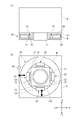
制振装置20は、主軸11の外周を覆う主軸カバー110(図3(b))を囲む円環状のウェイトWと、ウェイトWを水平方向に振動変位させるアクチュエータ21〜24と、変位計25と、制御装置10(図2)に組み込まれるx方向制御回路部30Xおよびy方向制御回路部30Yと、アクチュエータ21〜24にそれぞれ交流電流を供給する4つの駆動部(そのうちの2つが34,35)とを備えて構成されている。図3(a)では、主軸カバー110(図3(b))の図示を省略している。
この制振装置20は、アクチュエータ21〜24によりウェイトWをラム6の振動変位の向きとは逆向きに加振してラム6の振動を減衰させる能動型とされている。
[Vibration control device]
The
The
ウェイトWおよびアクチュエータ21〜24は、ラム6の先端に固定される架台27に設けられるとともに、カバー28(図3(a)参照。図3(b)では図示省略)により覆われている。
ウェイトWは、円環状のゴム部材29を介して架台27に吊られている。ウェイトWがアクチュエータ21〜24により変位されるとき、ゴム部材29によりガイドされる。これにより、ウェイトWはラム6に対して変位される。
The weight W and the
The weight W is suspended from the
変位計25は、ラム6の先端に設けられており、ラム6の変位からウェイトWの変位を差し引くことで得られる両者の相対変位を計測する。変位計25は、x方向の相対変位とy方向の相対変位との各々を計測する。それらの相対変位がいずれも0のとき、制振装置20によってラム6の振動が完全に打ち消されている。
なお、x方向の相対変位を計測する変位計と、y方向の相対変位を計測する変位計とを個別に設けることもできる。
The
A displacement meter that measures the relative displacement in the x direction and a displacement meter that measures the relative displacement in the y direction can also be provided separately.
〔アクチュエータ〕
アクチュエータ21〜24の各々は、コイルおよび鉄心を有する電磁石12と、鉄などの強磁性体13を有している。電磁石12はウェイトWの内周に固定されている。強磁性体13は、架台27に固定されて電磁石12に対向する。電磁石12のコイルに通電されていないとき、電磁石12と強磁性体13との間には、ウェイトWの変位を許容する隙間があいている。
電磁石12のコイルに電流を供給すると発生する磁力により、強磁性体13に向けて電磁石12が吸引される。これにより、架台27が固定されるラム6に対してウェイトWが変位される。
[Actuator]
Each of the
The
アクチュエータ21〜24のうち、対をなす2つのアクチュエータ21,22は、主軸11に直交するx方向およびy方向のうち、x方向に沿って配置されている。アクチュエータ21,22は、x方向制御回路部30Xに接続されている。
これらのアクチュエータ21およびアクチュエータ22は、主軸11に対して点対称に形成されている。これらアクチュエータ21およびアクチュエータ22の各々の電磁石には、直流電流が供給され、それに加えて、互いに逆位相となる交流電流が供給される。それにより、ウェイトWは、+x方向の変位と、−x方向の変位とを交互に繰り返して振動する。
Of the
The
他の対をなす2つのアクチュエータ23,24は、y方向に沿って配置されている。アクチュエータ23,24は、y方向に対応するy方向制御回路部30Yに接続されている。
これらのアクチュエータ23およびアクチュエータ24も、主軸11に対して点対称に形成されている。そして、アクチュエータ23,24の各々の電磁石に直流電流に加えて、互いに逆位相となる交流電流が供給されることにより、ウェイトWは、+y方向の変位と、−y方向の変位とを交互に繰り返して振動する。
The other pair of two
These
〔制御回路部〕
図4を参照し、アクチュエータ21,22を駆動制御するx方向制御回路部30Xについて説明する。
x方向制御回路部30Xは、制御定数設定部31と、ゲイン設定部32と、位相シフトフィルタ33とを備えている。
ゲイン設定部32および位相シフトフィルタ33により、制御定数ωおよび変位計25により計測される相対変位dxに基づいて、ゲインおよび位相を設定する演算部が構成される。
以下、制御定数設定部31、ゲイン設定部32、および位相シフトフィルタ33について順に説明する。
併せて、x方向制御回路部30Xにより演算された制御信号に基づく電流をアクチュエータ21,22に供給する駆動部34,35についても説明する。
[Control circuit section]
With reference to FIG. 4, the x-direction control circuit unit 30 </ b> X that drives and controls the
The x-direction
The
Hereinafter, the control
In addition, the
〔制御定数設定部〕
制御定数設定部31は、制御装置10が備えるNC装置15に接続されている。制御定数設定部31は、NC装置15により得られるラム6の現在位置と、それに対応する固有振動数とを示すテーブルデータに基づいてラム6の固有振動数を割り出すことができる。ラム6の固有振動数は、突き出し量が多いほど低くなる。そして、突き出し量が多いほど、ラム6の動剛性が低下する。
なお、動剛性は、振幅Fの周期的な加振力が構造物(ここではラム6)に作用しており、周期的な応答として変位Xを得るとき、F/Xを伝達関数の形で表したものをいう。
制御定数設定部31は、さらに、割り出した固有振動数に応じた制御定数ωを設定する。制御定数ωは、固有振動数を補正した値に相当する。制御定数設定部31は、制御定数ωを制御電流I(制御信号)ととともにゲイン設定部32および位相シフトフィルタ33に出力する。
[Control constant setting section]
The control
Note that the dynamic stiffness is such that when a periodic excitation force with an amplitude F acts on the structure (here, the ram 6) and the displacement X is obtained as a periodic response, F / X is expressed in the form of a transfer function. Say what you represent.
The control
〔ゲイン設定部〕
ゲイン設定部32は、変位計25により計測されるx方向の相対変位dxと、制御定数ωに基づいて、制御電流Iのゲイン(利得)を設定する。ゲインは、制御定数または相対変位に比例する比例ゲインとすることができる。
ここで、変位計25により計測される相対変位dx(ラム6のx方向変位−ウェイトWのx方向変位)からは次のように判断できる。この相対変位dxが「0」または「0」に近ければ、ラム6の振動とは逆位相で加振されるウェイトWの振幅がラム6の振幅とつり合っているためにラム6の振動が十分に減衰されている。つまり、駆動部34,35によってアクチュエータ21,22に供給される電流により、アクチュエータ21,22がウェイトWを振動変位させる力(加振力)が過不足なく得られている。
一方、相対変位dxが絶対値で所定値以上であれば、ウェイトWに与える加振力を増減させる必要がある。つまり、相対変位dxが正のとき、加振力を増大させ、相対変位dxが負のとき、加振力を減少させる必要がある。
[Gain setting section]
The
Here, from the relative displacement dx measured by the displacement meter 25 (the displacement in the x direction of the
On the other hand, if the relative displacement dx is an absolute value or more, it is necessary to increase or decrease the excitation force applied to the weight W. That is, it is necessary to increase the excitation force when the relative displacement dx is positive and to decrease the excitation force when the relative displacement dx is negative.
また、制御定数ωからは、次のように判断できる。制御定数ωが大きいと(固有振動数が高い)、ラム6の突き出し量が少ないことを意味するから、ラム6の動剛性が高い。したがって、ラム6の振幅が小さいので、小さい加振力で足りる。これとは逆に、制御定数ωが小さいと(固有振動数が低い)、ラム6の突き出し量が多いことを意味するから、ラム6の動剛性が低い。したがって、ラム6の振幅が大きいので、制振には大きな加振力が必要となる。
以上より、ゲイン設定部32は、ラム6とウェイトWの相対変位dxと、制御定数ωとを重み付けし、両者に基づいて必要な加振力を導く。その加振力に基づいて、ゲインを増減、あるいは維持する。
Further, it can be determined from the control constant ω as follows. When the control constant ω is large (the natural frequency is high), it means that the protruding amount of the
As described above, the
〔位相シフトフィルタ〕
位相シフトフィルタ33は、ゲイン設定部32から制御定数ωおよび制御電圧Vを受け取り、制御定数ωに基づいて制御電圧Vを演算する。
位相シフトフィルタ33は、特定周波数およびその近傍の信号のみを通過させる帯域通過フィルタと、帯域通過フィルタを通過した信号の符号を反転させる反転フィルタとを含んで構成されている。この位相シフトフィルタ33に制御電圧Vおよび制御定数ωを入力すると、帯域通過フィルタにより、制御定数ωに対応する共振周波数に設定されるとともに、反転フィルタによってラム6の振動位相に対して位相が逆転された制御電圧Vが出力される。
(Phase shift filter)
The
The
〔駆動部〕
駆動部34は、位相シフトフィルタ33から制御電圧Vを受け取り、駆動電流に変換してアクチュエータ21に供給する。
駆動部35は、位相シフトフィルタ33から制御電圧Vの位相を逆転させた電圧を受け取り、駆動電流に変換してアクチュエータ22に供給する。
そうすると、アクチュエータ21にはラム6の振動位相とは逆位相の電流が供給され、アクチュエータ22にはラム6の振動位相とは同相の電流が供給されるので、ウェイトWは、ラム6の振動位相とは逆位相で振動変位する。
〔Drive part〕
The
The
Then, a current having a phase opposite to the vibration phase of the
y方向制御回路部30Yは、アクチュエータ23,24を制御対象とする点を除いてx方向制御回路部30Xと同様に構成されている。y方向制御回路部30Yも、制御定数設定部と、ゲイン設定部と、位相シフトフィルタとを備えている。y方向制御回路部30Yは、変位計25により計測されたy方向の相対変位dyに基づいて演算を行う。y方向制御回路部30Yによる演算結果は、y方向に係る一対の駆動部(図示しない)に渡される。これらの駆動部は、y方向制御回路部30Yにより演算された制御信号に基づく電流をy方向のアクチュエータ23,24に供給する。
ここで、y方向制御回路部30Yの制御定数設定部では、ラム6の固有振動数を補正して制御定数ωを設定するときに、その補正量をx方向制御回路部30Xとは変えることができる。これにより、ラム6の固有振動数がx方向とy方向で異なる場合でも効率よく制振できる。
なお、x方向、y方向で同じ制御定数ωを用いる場合には、x方向制御回路部30Xおよびy方向制御回路部30Yの一方の制御定数設定部を省いて、これら制御回路部30X,30Yが同じ制御定数設定部を用いるように構成することもできる。
The y-direction
Here, when the control constant setting unit of the y-direction
When the same control constant ω is used in the x direction and the y direction, one control constant setting unit of the x direction
〔制振装置の作用および効果〕
上記のように構成された加工機1では、ラム6とウェイトWの相対変位dx,dyを変位計25で観測しながら、x方向制御回路部30Xおよびy方向制御回路部30Yの各々を動作させてウェイトWを振動させることにより、ワーク9の加工時にラム6に生じる振動を減衰させる。
x方向制御回路部30Xは、上述のように、制御定数設定部31により、NC装置15から得られるラム6の位置に応じたラム6の固有振動数を求め、その固有振動数に基づいて制御定数ωを設定する。そして、ゲイン設定部32により、制御定数ωと、相対変位dxに基づいて必要な加振力に対応するゲインを定めるとともに、位相シフトフィルタ33により、ラム6の共振周波数に対応する周波数、およびラム6のx方向の振動位相とは逆の位相を定める。そして、駆動部34,35によりアクチュエータ21,22を動作させることでウェイトWを加振すると、ラム6のx方向の振動が打ち消される。
[Operation and effect of vibration control device]
In the
As described above, the x-direction
y方向制御回路部30Yも、同様に、NC装置15から得られるラム6の位置に基づいてラム6の固有振動数を求め、その固有振動数に応じた制御定数ωを設定する。そして、制御定数ωと、相対変位dyに基づいて必要な加振力に対応するゲインを定めるとともに、ラム6の共振周波数に対応する周波数、およびラム6のy方向の振動位相とは逆の位相を定める。そして、アクチュエータ23に対応する駆動部と、アクチュエータ24に対応する駆動部とによってアクチュエータ23,24を動作させることでウェイトWを加振すると、ラム6のy方向の振動が打ち消される。
Similarly, the y-direction
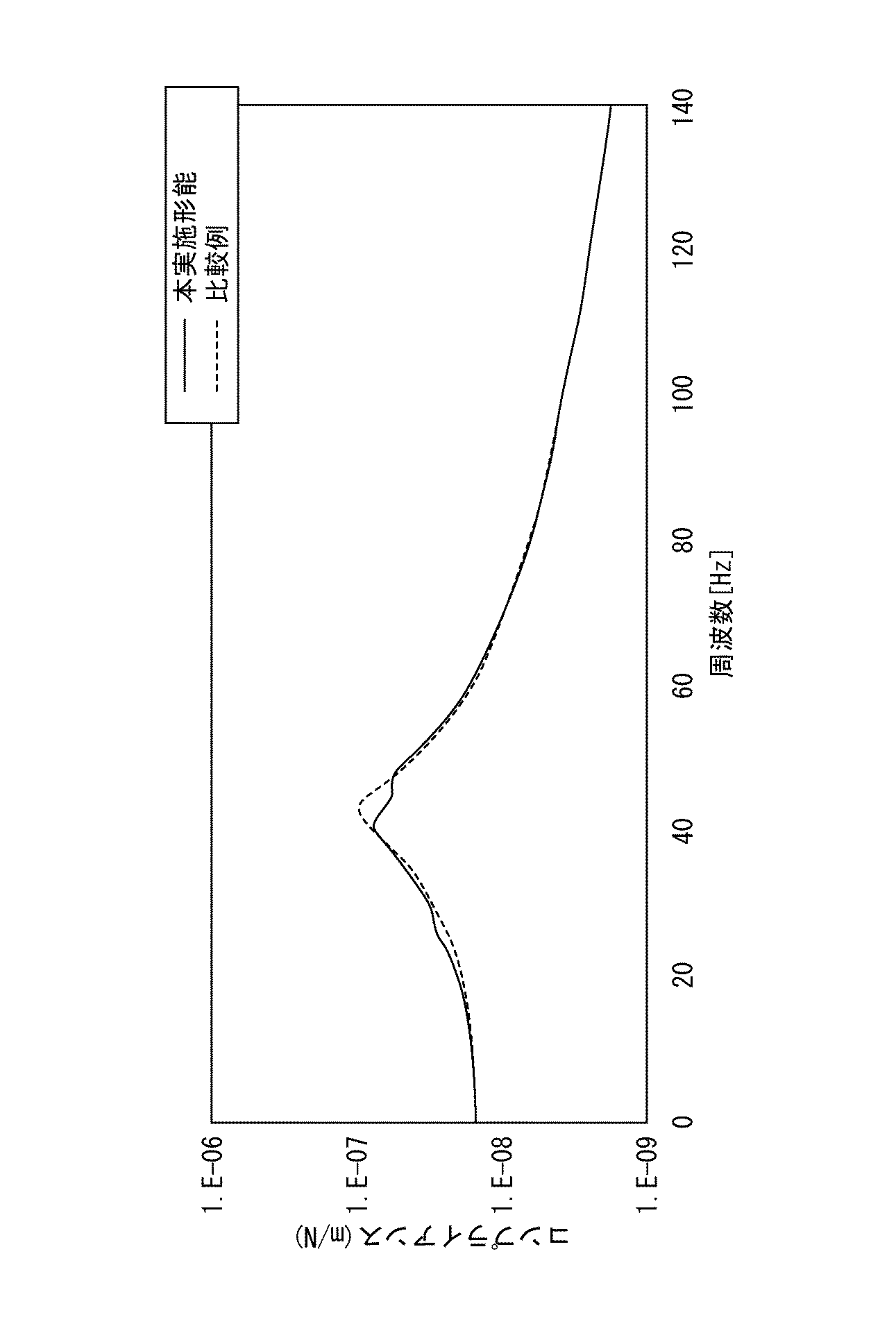
図5は、本実施形態におけるラム6のコンプライアンス曲線(実線)と、比較例におけるラム6のコンプライアンス曲線(破線)を示す。
コンプライアンスは、構造物(ここではラム6)が外力を受けることで変位する傾向を示す数値で、単位外力当たりの構造物の振幅変位により定められる。つまり、コンプライアンスは動剛性の逆数である。コンプライアンスが大きい程、構造物の動剛性が低くなる。コンプライアンス曲線は、コンプライアンス(縦軸)を周波数(横軸)の関数として示すものである。
FIG. 5 shows a compliance curve (solid line) of the
The compliance is a numerical value indicating a tendency of the structure (here, the ram 6) to be displaced by receiving an external force, and is determined by an amplitude displacement of the structure per unit external force. In other words, compliance is the reciprocal of dynamic stiffness. The greater the compliance, the lower the dynamic stiffness of the structure. The compliance curve shows compliance (vertical axis) as a function of frequency (horizontal axis).
比較例でも、本実施形態と同じ動剛性のラム6と、ウェイトWおよびアクチュエータ21〜24を有する制振装置を備えている。そして、変位計25により計測されるラム6とウェイトWの相対変位をフィードバック制御することで、アクチュエータ21〜24によりウェイトWを振動変位させる。
但し、比較例における制御は、ある突き出し量のときのラム6の固有振動数に基づいてチューニングされたものであって、本実施形態のようにラム6の突き出し量に応じて可変な固有振動数に基づいて行われるものではない。
Also in the comparative example, a
However, the control in the comparative example is tuned on the basis of the natural frequency of the
図5に示すコンプライアンス曲線のピークは、ラム6の突き出し量が最大で、それよりも突き出し量が小さいときに対して動剛性が最も低い状態を示す。ここで、本実施形態(実線)におけるラム6の共振のピークP1は、比較例(破線)におけるラム6の共振のピークP2よりも小さい。これは、制振装置20の作用によってラム6の固有振動が減衰されるためである。
一方、ピークP1付近以外は、本実施形態のコンプライアンス曲線(実線)は比較例のコンプライアンス曲線(破線)と同様である。
以上より、本実施形態によれば、ラム6の突き出し量が大であるときの動剛性を高めながら、ラム6のストロークの全体に亘り、制振効果を発揮させることができる。
The peak of the compliance curve shown in FIG. 5 shows a state in which the dynamic rigidity is the lowest when the protrusion amount of the
On the other hand, except for the vicinity of the peak P1, the compliance curve (solid line) of the present embodiment is the same as the compliance curve (broken line) of the comparative example.
As described above, according to the present embodiment, the vibration damping effect can be exhibited over the entire stroke of the
〔第2実施形態〕
上記実施形態では、位相シフトフィルタ33の出力に基づいて、ラム6の振動位相に対して逆の位相でウェイトWを振動変位させることによってラム6の振動低減を図っている。
その位相シフトフィルタ33に代えて、図6に示す第2実施形態では、制御回路部30X,30Yの変位信号に対して位相補償する位相補償回路43を用いる。その点を除いて、第2実施形態は第1実施形態と同様に構成されている。
第2実施形態以降の各実施形態においては、第1実施形態で説明した構成と同様の構成には同じ符号を付す。
[Second Embodiment]
In the above embodiment, the vibration of the
Instead of the
In each embodiment after the second embodiment, the same reference numerals are given to the same components as those described in the first embodiment.
位相補償回路43は、変位計25によりフィードバックされるラム6とウェイトWの相対変位を受け取り、その相対変位に対して、制御遅延の分だけ位相を進ませる。
このように、ラム6とウェイトWの相対変位に対して進み位相の加振力によりウェイトWを振動させることによって、ラム6に振動減衰効果を与える。
ここで、位相進み回路(要素)は、入力側の電圧をe1、出力側の電圧をe2、時定数をT1、定数をαとおくと、式(1)に示すように、分母側の時定数αT1[s]と分子側の時定数T1[s]で表すことができる。
ここでは、分母側の時定数をT2(=αT1)と表す代わりに、T2とT1の比をとって定数αとしている。
また、位相進み回路が有効な周波数領域の中心周波数は式(2)で表される。減衰される周波数は、式(2)に基づいて自動的に定まる。
第2実施形態によれば、ゲイン設定部32によりゲインを大きく設定しても、位相補償回路43により、共振周波数減衰を与えることができて、ラム6の振動を減衰することができる。
The
In this way, the weight W is vibrated by the exciting force of the leading phase with respect to the relative displacement between the
Here, the phase advance circuit (element) has an input side voltage e1, an output side voltage e2, a time constant T1, and a constant α, as shown in the equation (1), It can be expressed by a constant αT1 [s] and a time constant T1 [s] on the molecular side.
Here, instead of expressing the time constant on the denominator side as T2 (= αT1), the ratio of T2 and T1 is taken as the constant α.
Further, the center frequency in the frequency region where the phase advance circuit is effective is expressed by Expression (2). The frequency to be attenuated is automatically determined based on Equation (2).
According to the second embodiment, even if the
第2実施形態によっても、図5に実線で示すのと同様のコンプライアンス曲線が得られる。したがって、ラム6のストロークの全体に亘り、制振効果を発揮させながら、ラム6の突き出し量が大であるときの動剛性を高めることができる。
Also according to the second embodiment, the same compliance curve as shown by the solid line in FIG. 5 is obtained. Therefore, it is possible to increase the dynamic rigidity when the protruding amount of the
x方向制御回路部30Xおよびy方向制御回路部30Yには、上記の位相シフトフィルタ33、および位相補償回路43のいずれかを任意に選択して適用することができる。
位相シフトフィルタ33および位相補償回路43の選択は、ラム6およびウェイトWの振動特性や、ラム6とウェイトWの相対変位などに基づいて行うことができる。
例えば、ラム6とウェイトWのx方向の相対変位が大きいためにx方向ではゲインを大きく設定したいので、x方向制御回路部30Xには位相補償回路43を適用し、y方向の相対変位が小さいためにy方向ではゲインをさほど上げる必要がないので、y方向制御回路部30Yには位相シフトフィルタ33を適用する、といった使い方ができる。
Any one of the
The selection of the
For example, since the relative displacement in the x direction between the
〔第3実施形態〕
次に、本発明の第3実施形態について説明する。
本発明者らが、切削加工中のラム6の振動状況を調べるため、周波数分析を行ったところ、図7に示す結果が得られた。
[Third Embodiment]
Next, a third embodiment of the present invention will be described.
When the present inventors performed frequency analysis in order to investigate the vibration state of the
図7に示すように、切削加工中にラム6に生じている振動には、周波数(周波数域)により区別される複数の成分が含まれる。その成分のことを周波数成分と定義する。以下では、周波数成分のことを単に成分と言うことがある。
図7に示す例では、周波数が最も低いものがラム6の固有振動数(共振周波数)に対応する周波数成分(f0)である。その他に、ラム6に取り付けられた工具(例えばフライス)の刃によりワーク(例えば、図1のワーク9)が打撃されることで生じる強制振動の一次成分(f1)および二次成分(f2)がある。なお、強制振動の一次成分(f1)の周波数が固有振動数の成分(f0)の周波数よりも低い場合もある。
回転される工具がワークを打撃すると、ラム6の固有振動が励起されるとともに、工具がワークを周期的に打撃することで強制振動が生じる。強制振動の一次成分は、工具の刃の数と工具の回転数とを乗じた周波数(打撃周波数)に対応する。この強制振動は、二次以上の高調波成分を含んでおり、強制振動の二次成分は、打撃周波数の2倍の周波数に対応する。
なお、図7では、固有振動の成分、強制振動の一次成分、および強制振動の二次成分が、各々、単一の周波数に収束しているが、各々が所定の周波数域に分布している場合もある。
As shown in FIG. 7, the vibration generated in the
In the example shown in FIG. 7, the frequency component (f 0 ) corresponding to the natural frequency (resonance frequency) of the
When the rotated tool strikes the workpiece, the natural vibration of the
In FIG. 7, the natural vibration component, the primary component of forced vibration, and the secondary component of forced vibration each converge to a single frequency, but each is distributed in a predetermined frequency range. In some cases.
上記に示したように、ラム6に生じる振動には強制振動の成分も含まれる。図7に示す例のように、強制振動の一次成分の振幅が固有振動の振幅よりも大きい場合もあり、ラム6の強制振動が加工品位に与える影響は大である。
そこで、本実施形態では、強制振動の周波数で、強制振動とは逆位相でウェイトWを加振することにより、ラム6の制振を図る。
As described above, the vibration generated in the
Therefore, in this embodiment, the
図8に示すように、本実施形態の制振装置50は、加工機1(図1)の主軸11を保持するラム6に設けられるウェイトWと、ウェイトWを振動変位させるアクチュエータ21〜24と、変位計25と、加速度計26と、周波数分析装置16(周波数成分取得装置)と、アクチュエータ21,22を駆動制御するx方向制御回路部30Xと、アクチュエータ23,24を駆動制御する図示しないy方向制御回路部と、アクチュエータ21〜24にそれぞれ交流電流を供給する4つの駆動部(そのうちの2つが34,35)とを備える。
As shown in FIG. 8, the
加速度計26は、ラム6に設けられており、ラム6の加速度を計測する。
加速度計26は、ラム6のx方向の加速度とy方向の加速度との各々を計測する。
なお、x方向の相対変位を計測する加速度計と、y方向の相対変位を計測する加速度計とを別々に設けることもできる。
The
The
An accelerometer that measures the relative displacement in the x direction and an accelerometer that measures the relative displacement in the y direction can be provided separately.
周波数分析装置16は、加速度計26により計測されたラム6の加速度を用いてラム6の振動の周波数を分析する。周波数分析装置16により、例えば図7に示すような分析結果が得られる。
The
本実施形態のx方向制御回路部30Xは、制御定数設定部51と、ゲイン設定部32と、位相シフトフィルタ33とを備える。
制御定数設定部51は、周波数分析装置16による分析結果に含まれる複数の周波数成分から、強制振動の一次成分を選択し、その周波数に応じた制御定数を設定する。
強制振動の一次成分が単一の周波数ではなく、近接する周波数の集合(周波数域)からなるものである場合には、その周波数域の代表値(例えば中心値)を制御定数ωに設定する。
制御定数設定部51は、制御定数ωを制御電流I(制御信号)ととともにゲイン設定部32および位相シフトフィルタ33に出力する。
The x-direction control circuit unit 30 </ b> X of the present embodiment includes a control
The control
When the primary component of the forced vibration is not a single frequency but a set of adjacent frequencies (frequency range), a representative value (for example, a center value) in the frequency range is set as the control constant ω.
The control
分析結果に含まれる固有振動成分、強制振動の一次成分、および強制振動の二次以上の成分を互いに判別するために、適宜な閾値やテーブルデータ、相関式等を用いることができる。
例えば、NC装置15(図4)から得られるラム6の現在位置と、それに対応する固有振動数とを示すテーブルデータに基づいてラム6の固有振動数を割り出し、分析結果から固有振動数に適合するものを除き、残された成分のうち、振幅が閾値以上の成分を強制振動の一次成分であると判定することができる。
分析結果から固有振動数の成分を除くと、閾値以上の振幅のものが残されない場合は、固有振動数と強制振動の一次成分の周波数とがほぼ一致する場合に該当する。この場合には、分析結果において固有振動数に適合するものを強制振動の一次成分でもあると判定することができる。
Appropriate threshold values, table data, correlation equations, and the like can be used to discriminate the natural vibration component, the primary component of the forced vibration, and the secondary and higher components of the forced vibration included in the analysis result.
For example, the natural frequency of the
If the component of the natural frequency is excluded from the analysis result, a case where an amplitude greater than or equal to the threshold value is not left corresponds to a case where the natural frequency and the frequency of the primary component of the forced vibration substantially coincide. In this case, the analysis result that matches the natural frequency can be determined to be the primary component of the forced vibration.
ゲイン設定部32および位相シフトフィルタ33は、第1実施形態と同様に作用するので、簡略に説明する。
ゲイン設定部32は、制御定数設定部51により設定された制御定数ωと、変位計25により計測された相対変位dxとに基づいて、制御電流Iのゲインを設定する。
ここで、上述したように、ラム6とウェイトWの相対変位dxが「0」または「0」に近ければ、アクチュエータ21,22がウェイトWを振動変位させる力(加振力)が過不足なく得られている。一方、相対変位dxが絶対値で所定値以上であれば、ウェイトWに与える加振力を増減させる必要がある。
また、制御定数ωが大きいと(強制振動の周波数が高い)、ラム6の振幅が小さいので、小さい加振力で足りる。これとは逆に、制御定数ωが小さいと(強制振動の周波数が低い)、ラム6の振幅が大きいので、制振には大きな加振力が必要となる。
以上より、ゲイン設定部32は、相対変位dxと、制御定数ωとを重み付けし、両者に基づいて必要な加振力を導く。その加振力に基づいて、ゲインを増減、あるいは維持する。
The
The
Here, as described above, if the relative displacement dx between the
Further, when the control constant ω is large (the forced vibration frequency is high), the amplitude of the
As described above, the
また、位相シフトフィルタ33は、ゲイン設定部32から制御定数ωおよび制御電圧Vを受け取り、制御定数ωに基づいて制御電圧Vを演算する。位相シフトフィルタ33の演算結果として、制御定数ωに対応する共振周波数であり、ラム6に生じる強制振動の一次成分の振動位相に対して位相が逆転された制御電圧Vが出力される。
The
なお、本実施形態において、位相シフトフィルタ33の代わりに位相補償回路43(図6)を用いることもできる。
In the present embodiment, the phase compensation circuit 43 (FIG. 6) can be used instead of the
駆動部34は、位相シフトフィルタ33から制御電圧Vを受け取り、駆動電流に変換してアクチュエータ21に供給する。
駆動部35は、位相シフトフィルタ33から制御電圧Vの位相を逆転させた電圧を受け取り、駆動電流に変換してアクチュエータ22に供給する。
そうすると、アクチュエータ21にはラム6の強制振動の一次成分の位相とは逆位相の電流が供給され、アクチュエータ22にはラム6の強制振動の一次成分の位相とは同相の電流が供給されるので、ウェイトWは、ラム6の強制振動の一次成分の位相とは逆位相で振動変位する。
The
The
Then, a current having a phase opposite to the phase of the primary component of the forced vibration of the
本実施形態のy方向制御回路部は、本実施形態のx方向制御回路部30Xと同様に、制御定数設定部51と、ゲイン設定部32と、位相シフトフィルタ33と、アクチュエータ23に交流電流を供給する駆動部と、アクチュエータ24に交流電流を供給する駆動部とを備えて構成される。
y方向制御回路部は、変位計25により計測されたy方向の相対変位dyを参照する点、およびアクチュエータ23,24を駆動対象とする点を除いて、x方向制御回路部30Xと同様に動作する。
Similarly to the x-direction
The y-direction control circuit unit operates in the same manner as the x-direction
以上で説明した本実施形態の構成によれば、ラム6とウェイトWの相対変位dx,dyを変位計25で観測しながら、x方向制御回路部30Xおよびy方向制御回路部の各々を動作させてウェイトWを振動させることにより、ワーク9の加工時にラム6に生じる振動を減衰させる。
x方向制御回路部30Xは、上述のように、周波数分析結果から強制振動の一次成分に応じて制御定数ωを設定する。そして、ゲイン設定部32により、制御定数ωと、相対変位dxに基づいて必要な加振力に対応するゲインを設定するとともに、位相シフトフィルタ33により、強制振動の一次成分に対応する周波数、およびラム6のx方向の振動位相とは逆の位相を設定する。そして、駆動部34,35によりアクチュエータ21,22を動作させることでウェイトWを加振すると、ラム6に生じるx方向の強制振動が減衰される。
According to the configuration of the present embodiment described above, each of the x direction
As described above, the x-direction
y方向制御回路部も、x方向制御回路部30Xと同様に動作する。そうしてアクチュエータ23,24が動作することでウェイトWが加振されると、ラム6に生じるy方向の強制振動が減衰される。
The y-direction control circuit unit operates in the same manner as the x-direction
本実施形態では、ワークの加工中、ラム6の加速度を用いて周波数分析装置16により逐次、強制振動の周波数を取得し、それに基づく制御定数ωを設定して制御することができる。そのため、工具の回転数を変更したり、刃数の異なる工具に交換することで強制振動の周波数が変わっても、適切な制御定数を設定し、回転数変更や工具交換の前後に亘り、継続して強制振動を減衰させることができる。
In the present embodiment, during machining of the workpiece, the frequency of the forced vibration can be sequentially acquired by the
本実施形態において、強制振動の二次成分の周波数に応じた制御定数を用いる制御系を追加することもできる。その場合は、本実施形態のx方向制御回路部30Xは、一次成分用の制御定数設定部51、ゲイン設定部32、および位相シフトフィルタ33とは別に、二次成分用の制御定数設定部、ゲイン設定部、および位相シフトフィルタを備える。y方向制御回路部30Yも同様である。
そして、二次成分用の制御回路部は、周波数分析装置16による分析結果を受け取り、強制振動の二次成分の周波数に応じた制御定数を設定する。以降、一次成分について上述したのと同様の処理を行えばよい。
In the present embodiment, a control system using a control constant corresponding to the frequency of the secondary component of forced vibration can be added. In that case, the x-direction
And the control circuit part for secondary components receives the analysis result by the
ところで、ワークの加工中、工具の回転数が一定で、用いる工具の刃数も一定である場合は、周波数分析装置16により逐次、強制振動の周波数を取得し、それに基づく制御定数ωを設定し直す必要がない。
上述したように、工具の回転数と工具の刃数とを乗じて得られる値が、強制振動の一次成分の周波数に相当する。また、その値を2倍した値が強制振動の二次成分の周波数に相当する。
したがって、本実施形態の構成(図8)から加速度計26および周波数分析装置16を廃し、工具の回転数および工具の刃数の計算により得られる値に応じた一律の制御定数ωを用いて制御を行うことも可能である。
ここで、強制振動の周波数が一意に定まる場合でも、ラム6の位置(突き出し量)に応じて強制振動の振幅は変化する。そのため、強制振動を減衰させるのに必要な加振力が得られるように、ゲイン設定、およびその後の位相操作が逐次行われる。
By the way, when the number of rotations of the tool is constant and the number of blades of the tool to be used is constant during the machining of the workpiece, the
As described above, a value obtained by multiplying the number of rotations of the tool and the number of blades of the tool corresponds to the frequency of the primary component of forced vibration. A value obtained by doubling the value corresponds to the frequency of the secondary component of forced vibration.
Therefore, the
Here, even when the frequency of the forced vibration is uniquely determined, the amplitude of the forced vibration changes according to the position (protrusion amount) of the
〔第4実施形態〕
次に、本発明の第4実施形態について説明する。
第4実施形態の制振装置は、第1実施形態の構成(図4)と第3実施形態の構成(図8)とを備える。
図9に示すように、本実施形態の制振装置60は、加工機1(図1)の主軸11を保持するラム6に設けられるウェイトWと、ウェイトWを振動変位させるアクチュエータ21〜24と、変位計25と、加速度計26と、周波数分析装置16(周波数成分取得装置)と、アクチュエータ21,22を駆動制御するx方向制御回路部30Xと、アクチュエータ23,24を駆動制御する図示しないy方向制御回路部と、アクチュエータ21〜24にそれぞれ交流電流を供給する4つの駆動部(そのうちの2つが34,35)とを備える。
[Fourth Embodiment]
Next, a fourth embodiment of the present invention will be described.
The vibration damping device of the fourth embodiment includes the configuration of the first embodiment (FIG. 4) and the configuration of the third embodiment (FIG. 8).
As shown in FIG. 9, the
x方向制御回路部30Xは、ラム6に生じる固有振動を制振対象とする第1制御回路部61と、ラム6に生じる強制振動を制振対象とする第2制御回路部62とを備える。
The x-direction control circuit unit 30 </ b> X includes a first
第1制御回路部61は、第1制御定数設定部31と、ゲイン設定部32と、位相シフトフィルタ33とを備える。
第2制御回路部62は、第2制御定数設定部51と、ゲイン設定部32と、位相シフトフィルタ33とを備える。
The first
The second
まず、第2制御回路部61の各構成について説明する。
第1制御定数設定部31は、第1実施形態の制御定数設定部31(図4)と同様に構成されており、NC装置15から得られるラム6の位置の位置と、それに対応する固有振動数とを示すテーブルデータに基づいてラム6の固有振動数を割り出す。そして、この固有振動数に応じた制御定数ω1(第1制御定数)を設定する。
第1制御定数設定部31は、制御定数ω1を制御電流I1(制御信号)とともにゲイン設定部32および位相シフトフィルタ33に出力する。
また、第1制御定数設定部31は、割り出した固有振動数を第2制御定数設定部51に送信する(図9の破線参照)。
First, each configuration of the second
The first control
The first control
The first control
ゲイン設定部32および位相シフトフィルタ33は、第1実施形態と同様に作用する。
ゲイン設定部32は、制御定数ω1と、変位計25により計測された相対変位dxとに基づいて、制御電流I1のゲインを設定する。
位相シフトフィルタ33は、ゲイン設定部32から制御定数ω1および制御電圧V1を受け取り、制御定数ω1に基づいて制御電圧V1を演算したものを駆動部34,35に出力する。位相シフトフィルタ33からは、ラム6の振動位相に対して位相が逆転された制御電圧V1が出力される。
The
The
The
次に、第2制御回路部62の各構成について説明する。
第2制御定数設定部51は、第3実施形態の制御定数設定部51(図8)と同様に構成される。第2制御定数設定部51は、周波数分析装置16による分析結果から、ラム6に生じる強制振動の周波数を取得し、その周波数に応じた制御定数ω2(第2制御定数)を設定する。
ここで、第2制御定数設定部51は、周波数分析装置16による分析結果において強制振動の周波数成分を抽出するために、第1制御定数設定部31から受信する固有振動数を用いることができる。つまり、分析結果から固有振動数に適合するものを除き、残された成分のうち、振幅が閾値以上の成分を強制振動の一次成分であると判定することができる。
但し、第2制御定数設定部51は、第1制御定数設定部31から固有振動数を受信することなく、NC装置15から得られるラム6の現在位置と、それに対応する固有振動数とを示すテーブルデータに基づいてラム6の固有振動数を割り出すこともできる。
第2制御定数設定部51は、制御定数ω2を制御電流I2(制御信号)とともにゲイン設定部32および位相シフトフィルタ33に出力する。
Next, each configuration of the second
The second control
Here, the second control
However, the second control
The second control
第2制御回路部62は、制御定数ω2を設定するプロセス(制御定数設定部)が第1制御回路部61とは異なるだけで、その後のゲイン設定部32および位相シフトフィルタ33による処理は、第1制御回路部61と同様である。
The second
つまり、ゲイン設定部32は、制御定数ω2と、変位計25により計測された相対変位dxとに基づいて、制御電流I2のゲインを設定する。
位相シフトフィルタ33は、ゲイン設定部32から制御定数ω2および制御電圧V2を受け取り、制御定数ω2に基づいて制御電圧V2を演算したものを駆動部34,35に出力する。位相シフトフィルタ33からは、強制振動の一次成分の振動位相に対して位相が逆転された制御電圧V2が出力される。
That is, the
The
次に、駆動部34,35について説明する。
駆動部34は、第1制御回路部61の位相シフトフィルタ33から制御電圧V1を受け取り、その電圧を駆動電流に変換してアクチュエータ21に供給する。また、駆動部35は、第2制御回路部62の位相シフトフィルタ33から制御電圧V2を受け取り、その電圧を駆動電流に変換してアクチュエータ21に供給する。
一方、駆動部35は、第1制御回路部61の位相シフトフィルタ33から制御電圧V1の位相を逆転させた電圧を受け取り、その電圧を駆動電流に変換してアクチュエータ22に供給する。また、駆動部35は、第2制御回路部62の位相シフトフィルタ33から制御電圧V2の位相を逆転させた電圧を受け取り、その電圧を駆動電流に変換してアクチュエータ22に供給する。
Next, the
The
On the other hand, the
以上より、アクチュエータ21,22は、第1制御回路部61の演算結果に基づく駆動電流と、第2制御回路部62の演算結果に基づく駆動電流との双方により駆動される。そうすると、ウェイトWが、ラム6の振動位相とは逆位相で加振されるとともに、ラム6に生じる強制振動の一次成分とは逆位相で加振される。
As described above, the
本実施形態では、上述の通り、第1制御回路部61および第2制御回路部62の各々の演算結果が、アクチュエータ21用の同じ駆動部34にそれぞれ出力される。アクチュエータ22も同様である。
但し、第1制御回路部61の演算結果が出力されるアクチュエータ21用の駆動部と、第1制御回路部61の演算結果が出力されるアクチュエータ21用の駆動部とが個別に構成されていてもよい。アクチュエータ22も同様に、第1制御回路部61および第2制御回路部62の各々に対して、個別に構成されていてもよい。
In the present embodiment, as described above, the calculation results of the first
However, the
本実施形態のy方向制御回路部は、本実施形態のx方向制御回路部30Xと同様に、第1制御回路部61と、第2制御回路部62とを備える。
y方向制御回路部は、変位計25により計測されたy方向の相対変位dyを参照する点、およびアクチュエータ23,24を駆動対象とする点を除いて、x方向制御回路部30Xと同様に動作する。
Similar to the x-direction
The y-direction control circuit unit operates in the same manner as the x-direction
以上で説明した本実施形態の構成によれば、ラム6とウェイトWの相対変位dx,dyを変位計25で観測しながら、x方向制御回路部30Xおよびy方向制御回路部の各々を動作させてウェイトWを振動させる。ウェイトWは、ラム6の固有振動数および相対変位に応じて設定されたゲインおよび位相で加振されるとともに、ラム6の強制振動の周波数および相対変位に応じて設定されたゲインおよび位相で加振される。
したがって、ラム6の固有振動と、工具がワークを打撃することで生じる強制振動との双方を減衰させることができる。
According to the configuration of the present embodiment described above, each of the x direction
Therefore, both the natural vibration of the
なお、本実施形態において、位相シフトフィルタ33の代わりに位相補償回路43(図6)を用いることもできる。下記の変形例(図10)においても同様である。
In the present embodiment, the phase compensation circuit 43 (FIG. 6) can be used instead of the
第4実施形態における第1制御定数設定部31は、NC装置15を利用してラム6の固有振動数を割り出すが、図10に示すように、周波数分析装置16による分析結果から、ラム6の現在位置に対応する固有振動数を得ることもできる。その場合、分析結果に含まれる固有振動成分、強制振動の一次成分、および強制振動の二次以上の成分を判別するために、適宜な閾値やテーブルデータ、相関式等を用いることができる。
The first control
上記以外にも、本発明の主旨を逸脱しない限り、上記実施形態で挙げた構成を取捨選択したり、他の構成に適宜変更することが可能である。
本発明は、主軸が水平に設けられる横中ぐり盤にも適用することができる。
In addition to the above, as long as the gist of the present invention is not deviated, the configuration described in the above embodiment can be selected or changed to another configuration as appropriate.
The present invention can also be applied to a horizontal boring machine in which the main shaft is provided horizontally.
1 加工機
2,3 コラム
4 クロスレール
5 サドル
6 ラム(主軸保持部材)
7 ベッド
8 テーブル
9 ワーク
10 制御装置
11 主軸
12 電磁石
13 強磁性体
15 NC装置
16 周波数分析装置(周波数成分取得装置)
20,50,60 制振装置
21,22 アクチュエータ(x方向アクチュエータ)
23,24 アクチュエータ(y方向アクチュエータ)
25 変位計
26 加速度計
27 架台
28 カバー
29 ゴム部材
30X x方向制御回路部
30Y y方向制御回路部
31 制御定数設定部
32 ゲイン設定部
33 位相シフトフィルタ(位相シフト部)
34,35 駆動部(x方向駆動部)
43 位相補償回路(位相補償部)
51 制御定数設定部
61 第1制御回路部
62 第2制御回路部
110 主軸カバー
W ウェイト
1 Processing
7
20, 50, 60
23, 24 Actuator (y-direction actuator)
25
34, 35 Drive unit (x-direction drive unit)
43 Phase compensation circuit (phase compensation unit)
51 Control
Claims (7)
前記ウェイトを振動変位させるアクチュエータと、
前記主軸保持部材と前記ウェイトとの相対変位を計測する変位計と、
前記アクチュエータを駆動制御するための制御信号を演算する制御回路部と、
前記制御回路部により演算された前記制御信号に基づく電流を前記アクチュエータに供給する駆動部と、を備え、
前記制御回路部は、
前記主軸保持部材の位置に対応する前記主軸保持部材の固有振動数に応じて制御定数を設定する制御定数設定部と、
前記制御定数および前記相対変位に基づいて、制御信号のゲインおよび位相を設定する演算部と、を備える、
ことを特徴とする制振装置。 A weight provided on a spindle holding member that holds the spindle of the processing machine;
An actuator for vibrating and displacing the weight;
A displacement meter for measuring relative displacement between the spindle holding member and the weight;
A control circuit unit for calculating a control signal for driving and controlling the actuator;
A drive unit that supplies a current based on the control signal calculated by the control circuit unit to the actuator,
The control circuit unit is
A control constant setting unit that sets a control constant according to the natural frequency of the main shaft holding member corresponding to the position of the main shaft holding member;
A calculation unit that sets a gain and a phase of a control signal based on the control constant and the relative displacement;
A vibration damping device characterized by that.
前記ウェイトを振動変位させるアクチュエータと、
前記主軸保持部材と前記ウェイトとの相対変位を計測する変位計と、
前記アクチュエータを駆動制御するための制御信号を演算する制御回路部と、
前記制御回路部により演算された前記制御信号に基づく電流を前記アクチュエータに供給する駆動部と、を備え、
前記制御回路部は、
ワークに対して工具が周期的に打撃することで前記主軸保持部材に生じる強制振動の周波数に応じて前記制御定数を設定する制御定数設定部と、
前記制御定数および前記相対変位に基づいて、前記制御信号のゲインおよび位相を設定する演算部と、を備える、
ことを特徴とする制振装置。 A weight provided on a spindle holding member that holds the spindle of the processing machine;
An actuator for vibrating and displacing the weight;
A displacement meter for measuring relative displacement between the spindle holding member and the weight;
A control circuit unit for calculating a control signal for driving and controlling the actuator;
A drive unit that supplies a current based on the control signal calculated by the control circuit unit to the actuator;
The control circuit unit is
A control constant setting unit for setting the control constant according to the frequency of forced vibration generated in the spindle holding member by periodically hitting the tool against the workpiece;
A calculation unit that sets a gain and a phase of the control signal based on the control constant and the relative displacement;
A vibration damping device characterized by that.
前記加速度を用いて、前記主軸保持部材に生じている振動の複数の周波数成分を取得する周波数成分取得装置と、を備え、
前記制御定数設定部は、
前記複数の周波数成分のうちの前記強制振動の周波数成分に応じて前記制御定数を設定する、
請求項2に記載の制振装置。 An accelerometer for measuring the acceleration of the spindle holding member;
A frequency component acquisition device that acquires a plurality of frequency components of vibration generated in the main shaft holding member using the acceleration; and
The control constant setting unit
Setting the control constant according to the frequency component of the forced vibration of the plurality of frequency components;
The vibration damping device according to claim 2.
前記制御定数および前記相対変位に基づいてゲインを設定するゲイン設定部と、
前記主軸保持部材の振動位相に対して位相を逆転させる位相シフト部と、を備える、
請求項1から3のいずれか一項に記載の制振装置。 The computing unit is
A gain setting unit for setting a gain based on the control constant and the relative displacement;
A phase shift unit that reverses the phase with respect to the vibration phase of the main shaft holding member,
The vibration damping device according to any one of claims 1 to 3.
前記制御定数および前記相対変位に基づいてゲインを設定するゲイン設定部と、
前記相対変位に対して位相を進ませる位相補償部と、を備える、
請求項1から3のいずれか一項に記載の制振装置。 The computing unit is
A gain setting unit for setting a gain based on the control constant and the relative displacement;
A phase compensator for advancing the phase with respect to the relative displacement,
The vibration damping device according to any one of claims 1 to 3.
前記制御回路部として、前記x方向アクチュエータを駆動制御するためのx方向制御回路部と、前記y方向アクチュエータを駆動制御するためのy方向制御回路部とが個別に構成され、
前記駆動部として、前記x方向アクチュエータに電流を供給するx方向駆動部と、前記y方向アクチュエータに電流を供給するy方向駆動部とが個別に構成される、
請求項1から5のいずれか一項に記載の制振装置。 The actuator includes an x-direction actuator that vibrates and displaces the weight in the x-direction among the x-direction and the y-direction orthogonal to the main axis, and a y-direction actuator that vibrates and displaces the weight in the y-direction.
As the control circuit unit, an x-direction control circuit unit for driving and controlling the x-direction actuator and a y-direction control circuit unit for driving and controlling the y-direction actuator are individually configured.
As the drive unit, an x-direction drive unit that supplies current to the x-direction actuator and a y-direction drive unit that supplies current to the y-direction actuator are individually configured.
The vibration damping device according to any one of claims 1 to 5.
前記ウェイトを振動変位させるアクチュエータと、
前記主軸保持部材と前記ウェイトとの相対変位を計測する変位計と、
前記アクチュエータを駆動制御するための第1制御信号を演算する第1制御回路部と、
前記アクチュエータを駆動制御するための第2制御信号を演算する第2制御回路部と、
前記第1制御回路部により演算された前記第1制御信号に基づく電流と、前記第2制御回路部により演算された前記第2制御信号に基づく電流とを前記アクチュエータに供給する駆動部と、を備え、
前記第1制御回路部は、
前記主軸保持部材の位置に対応する前記主軸保持部材の固有振動数に応じて第1制御定数を設定する第1制御定数設定部と、
前記第1制御定数および前記相対変位に基づいて、前記第1制御信号のゲインおよび位相を設定する第1演算部と、を備え、
前記第2制御回路部は、
ワークに対して工具が周期的に打撃することで前記主軸保持部材に生じる強制振動の周波数に応じて前記第2制御定数を設定する第2制御定数設定部と、
前記第2制御定数および前記相対変位に基づいて、前記第2制御信号のゲインおよび位相を設定する第2演算部と、を備える、
ことを特徴とする制振装置。 A weight provided on a spindle holding member that holds the spindle of the processing machine;
An actuator for vibrating and displacing the weight;
A displacement meter for measuring relative displacement between the spindle holding member and the weight;
A first control circuit unit for calculating a first control signal for driving and controlling the actuator;
A second control circuit unit for calculating a second control signal for driving and controlling the actuator;
A drive unit for supplying the actuator with a current based on the first control signal calculated by the first control circuit unit and a current based on the second control signal calculated by the second control circuit unit; Prepared,
The first control circuit unit includes:
A first control constant setting unit that sets a first control constant according to the natural frequency of the main shaft holding member corresponding to the position of the main shaft holding member;
A first calculator configured to set a gain and a phase of the first control signal based on the first control constant and the relative displacement;
The second control circuit unit includes:
A second control constant setting unit that sets the second control constant according to the frequency of forced vibration generated in the spindle holding member by periodically hitting the tool against the workpiece;
A second calculation unit that sets a gain and a phase of the second control signal based on the second control constant and the relative displacement,
A vibration damping device characterized by that.
Priority Applications (1)
| Application Number | Priority Date | Filing Date | Title |
|---|---|---|---|
| JP2013251463A JP6265718B2 (en) | 2013-02-25 | 2013-12-04 | Vibration control device |
Applications Claiming Priority (3)
| Application Number | Priority Date | Filing Date | Title |
|---|---|---|---|
| JP2013034358 | 2013-02-25 | ||
| JP2013034358 | 2013-02-25 | ||
| JP2013251463A JP6265718B2 (en) | 2013-02-25 | 2013-12-04 | Vibration control device |
Publications (2)
| Publication Number | Publication Date |
|---|---|
| JP2014184548A true JP2014184548A (en) | 2014-10-02 |
| JP6265718B2 JP6265718B2 (en) | 2018-01-24 |
Family
ID=51832610
Family Applications (1)
| Application Number | Title | Priority Date | Filing Date |
|---|---|---|---|
| JP2013251463A Expired - Fee Related JP6265718B2 (en) | 2013-02-25 | 2013-12-04 | Vibration control device |
Country Status (1)
| Country | Link |
|---|---|
| JP (1) | JP6265718B2 (en) |
Cited By (4)
| Publication number | Priority date | Publication date | Assignee | Title |
|---|---|---|---|---|
| CN109317712A (en) * | 2017-08-01 | 2019-02-12 | 上海电气电站设备有限公司 | For processing the Boring machine in steam turbine rotor coupling device hole |
| JP2019111600A (en) * | 2017-12-22 | 2019-07-11 | 株式会社日立製作所 | Damper gear and damping device |
| JP2019209419A (en) * | 2018-06-04 | 2019-12-12 | ファナック株式会社 | Numerical control device |
| JP7374460B2 (en) | 2019-10-10 | 2023-11-07 | 安田工業株式会社 | Machine tool vibration damping device |
Citations (5)
| Publication number | Priority date | Publication date | Assignee | Title |
|---|---|---|---|---|
| JPS6452636U (en) * | 1987-09-30 | 1989-03-31 | ||
| JP2002039177A (en) * | 2000-07-24 | 2002-02-06 | Ntn Corp | Non-contact bearing spindle device |
| JP2007229835A (en) * | 2006-02-28 | 2007-09-13 | Mitsubishi Heavy Ind Ltd | Damping device for machine tool |
| JP2008229806A (en) * | 2007-03-23 | 2008-10-02 | Jtekt Corp | Magnetic bearing device |
| US20110186323A1 (en) * | 2008-08-21 | 2011-08-04 | Kurt Schneider | Device for preventing vibrations in a tool spindle |
-
2013
- 2013-12-04 JP JP2013251463A patent/JP6265718B2/en not_active Expired - Fee Related
Patent Citations (5)
| Publication number | Priority date | Publication date | Assignee | Title |
|---|---|---|---|---|
| JPS6452636U (en) * | 1987-09-30 | 1989-03-31 | ||
| JP2002039177A (en) * | 2000-07-24 | 2002-02-06 | Ntn Corp | Non-contact bearing spindle device |
| JP2007229835A (en) * | 2006-02-28 | 2007-09-13 | Mitsubishi Heavy Ind Ltd | Damping device for machine tool |
| JP2008229806A (en) * | 2007-03-23 | 2008-10-02 | Jtekt Corp | Magnetic bearing device |
| US20110186323A1 (en) * | 2008-08-21 | 2011-08-04 | Kurt Schneider | Device for preventing vibrations in a tool spindle |
Cited By (4)
| Publication number | Priority date | Publication date | Assignee | Title |
|---|---|---|---|---|
| CN109317712A (en) * | 2017-08-01 | 2019-02-12 | 上海电气电站设备有限公司 | For processing the Boring machine in steam turbine rotor coupling device hole |
| JP2019111600A (en) * | 2017-12-22 | 2019-07-11 | 株式会社日立製作所 | Damper gear and damping device |
| JP2019209419A (en) * | 2018-06-04 | 2019-12-12 | ファナック株式会社 | Numerical control device |
| JP7374460B2 (en) | 2019-10-10 | 2023-11-07 | 安田工業株式会社 | Machine tool vibration damping device |
Also Published As
| Publication number | Publication date |
|---|---|
| JP6265718B2 (en) | 2018-01-24 |
Similar Documents
| Publication | Publication Date | Title |
|---|---|---|
| JP6265718B2 (en) | Vibration control device | |
| US10274939B2 (en) | Feed shaft control method and numerical control work device | |
| KR20090073254A (en) | Seismic isolation control system | |
| EP2708316B1 (en) | Inertia damper for suppressing vibrations in a machine tool | |
| JP4802839B2 (en) | Active vibration damping device and control method of active vibration damping device | |
| JP6903485B2 (en) | Vibration damping device and processing machine | |
| JP2010089256A (en) | Machine tool and vibration damping method for machine element | |
| JP2010507489A (en) | Machine Tools | |
| JP2010089256A6 (en) | Machine tool and vibration damping method for machine elements | |
| EP3227058B1 (en) | Control method for a hand-held power tool | |
| CN103052457A (en) | Machine tool and process for machining workpieces | |
| JP5824583B2 (en) | Machine tool vibration reduction apparatus and method | |
| JP2016189039A (en) | Numerical control device and control method | |
| JP2014014881A (en) | Dynamic characteristic calculation device and method of machine tool | |
| CN111203801A (en) | Active damping centerless grinding method | |
| US20180345451A1 (en) | Dynamically dampened centerless grinding machine tool and grinding method | |
| JP4605135B2 (en) | Processing equipment | |
| JP2014014882A (en) | Dynamic characteristic calculation device and method of machine tool | |
| JP2019128209A (en) | Vibration device and vibration test device with the vibration device | |
| RU2399475C2 (en) | Metal-cutting lathe with automatic control | |
| JP6922815B2 (en) | Numerical control device and control method | |
| KR101355948B1 (en) | Machine control device | |
| JP2021071895A (en) | Vibration suppressing method and vibration suppressing device | |
| JPWO2020044704A1 (en) | Vibration damping device | |
| JP2005212008A (en) | Active mass damper |
Legal Events
| Date | Code | Title | Description |
|---|---|---|---|
| A711 | Notification of change in applicant |
Free format text: JAPANESE INTERMEDIATE CODE: A712 Effective date: 20160301 |
|
| A521 | Request for written amendment filed |
Free format text: JAPANESE INTERMEDIATE CODE: A821 Effective date: 20160302 |
|
| A625 | Written request for application examination (by other person) |
Free format text: JAPANESE INTERMEDIATE CODE: A625 Effective date: 20160608 |
|
| A977 | Report on retrieval |
Free format text: JAPANESE INTERMEDIATE CODE: A971007 Effective date: 20170303 |
|
| A131 | Notification of reasons for refusal |
Free format text: JAPANESE INTERMEDIATE CODE: A131 Effective date: 20170321 |
|
| A521 | Request for written amendment filed |
Free format text: JAPANESE INTERMEDIATE CODE: A523 Effective date: 20170519 |
|
| A131 | Notification of reasons for refusal |
Free format text: JAPANESE INTERMEDIATE CODE: A131 Effective date: 20171031 |
|
| A521 | Request for written amendment filed |
Free format text: JAPANESE INTERMEDIATE CODE: A523 Effective date: 20171122 |
|
| TRDD | Decision of grant or rejection written | ||
| A01 | Written decision to grant a patent or to grant a registration (utility model) |
Free format text: JAPANESE INTERMEDIATE CODE: A01 Effective date: 20171212 |
|
| R150 | Certificate of patent or registration of utility model |
Ref document number: 6265718 Country of ref document: JP Free format text: JAPANESE INTERMEDIATE CODE: R150 |
|
| LAPS | Cancellation because of no payment of annual fees |