JP2014178011A - Rotary damper - Google Patents

Rotary damper Download PDF

Info

Publication number
JP2014178011A
JP2014178011A JP2013053326A JP2013053326A JP2014178011A JP 2014178011 A JP2014178011 A JP 2014178011A JP 2013053326 A JP2013053326 A JP 2013053326A JP 2013053326 A JP2013053326 A JP 2013053326A JP 2014178011 A JP2014178011 A JP 2014178011A
Authority
JP
Japan
Prior art keywords
piston
communication groove
communication
chamber
rotor
Prior art date
Legal status (The legal status is an assumption and is not a legal conclusion. Google has not performed a legal analysis and makes no representation as to the accuracy of the status listed.)
Pending
Application number
JP2013053326A
Other languages
Japanese (ja)
Inventor
Masahiro Yoshida
正浩 吉田
Current Assignee (The listed assignees may be inaccurate. Google has not performed a legal analysis and makes no representation or warranty as to the accuracy of the list.)
Sugatsune Kogyo Co Ltd
Original Assignee
Sugatsune Kogyo Co Ltd
Priority date (The priority date is an assumption and is not a legal conclusion. Google has not performed a legal analysis and makes no representation as to the accuracy of the date listed.)
Filing date
Publication date
Application filed by Sugatsune Kogyo Co Ltd filed Critical Sugatsune Kogyo Co Ltd
Priority to JP2013053326A priority Critical patent/JP2014178011A/en
Publication of JP2014178011A publication Critical patent/JP2014178011A/en
Pending legal-status Critical Current

Links

Images

Landscapes

  • Fluid-Damping Devices (AREA)

Abstract

PROBLEM TO BE SOLVED: To provide a rotary damper capable of rotating a rotor at a higher speed to open a communication passage, when the communication passage is opened by a valve element, thereby the rotor is rotated to open the same.SOLUTION: A first communication groove 7A is formed on an inner peripheral face of an accommodation hole of a casing 1. A second communication groove 7B is formed on an outer peripheral face of a piston 3. The first communication groove 7A and the second communication groove 7B are disposed on the same position in the circumferential direction of the accommodation hole so that the first communication groove 7A and the second communication groove 7B configure one communication hole 7 in the shape of one hole.

Description

この発明は、躯体と回転体との間に設けられ、回転体の回転速度を低速に抑えるための回転ダンパに関する。   The present invention relates to a rotary damper that is provided between a housing and a rotating body and suppresses the rotational speed of the rotating body to a low speed.

一般に、この種の回転ダンパは、下記特許文献1に記載されているように、一端部が開口し、他端部が底部によって閉じられた収容孔を有するケーシングと、収容孔の開口部側の端部に回転可能に設けられたロータと、このロータと底部との間の収容孔の内部に、摺動可能に、かつ回転不能に設けられたピストンとを備えている。ロータには、雄ねじが形成されている。一方、ピストンには、ねじ孔が形成されている。このねじ孔には、雄ねじが螺合されている。したがって、ロータが回転すると、ピストンがケーシングの軸線方向へ移動する。例えば、ロータが時計方向へ回転すると、ピストンが底部側へ移動し、ロータが反時計方向へ回転すると、ピストンがロータ側へ移動する。   In general, as described in Patent Document 1 below, this type of rotary damper includes a casing having an accommodation hole whose one end is open and the other end is closed by a bottom, and an opening side of the accommodation hole. A rotor provided rotatably at the end, and a piston provided so as to be slidable and non-rotatable inside an accommodation hole between the rotor and the bottom. A male screw is formed on the rotor. On the other hand, a screw hole is formed in the piston. A male screw is screwed into the screw hole. Therefore, when the rotor rotates, the piston moves in the axial direction of the casing. For example, when the rotor rotates clockwise, the piston moves to the bottom side, and when the rotor rotates counterclockwise, the piston moves to the rotor side.

収容孔の内部にピストンが設けられることにより、収容孔の内部がロータ側の第1の室と、底部側の第2の室とに区分されている。第1及び第2の室には、粘性流体等の流体が充填されている。第1及び第2の室は、連通路によって互いに連通されている。   By providing the piston inside the accommodation hole, the interior of the accommodation hole is divided into a first chamber on the rotor side and a second chamber on the bottom side. The first and second chambers are filled with a fluid such as a viscous fluid. The first and second chambers communicate with each other through a communication path.

ピストンには、弁体が設けられている。この弁体は、連通路を開閉するためのものであり、ピストンが底部側へ移動するときには連通路を閉じ、ピストンがロータ側へ移動するときには連通路を開く。弁体が連通路を閉じると、第2の室内の流体がオリフィス等の抵抗路を通って第1室内に流入する。このときの流通抵抗により、ピストンの移動速度が低速に抑えられ、ひいてはロータの回転速度が低速に抑えられる。弁体が連通路を開くと、第1の室内の流体が連通路を通って第2の室内に流入する。連通路の流通抵抗は小さい。したがって、ピストンが高速で移動することができ、ロータが高速で回転することができる。   The piston is provided with a valve body. This valve body is for opening and closing the communication path, and closes the communication path when the piston moves to the bottom side, and opens the communication path when the piston moves to the rotor side. When the valve body closes the communication passage, the fluid in the second chamber flows into the first chamber through a resistance path such as an orifice. Due to the flow resistance at this time, the moving speed of the piston is suppressed to a low speed, and consequently the rotational speed of the rotor is suppressed to a low speed. When the valve element opens the communication path, the fluid in the first chamber flows into the second chamber through the communication path. The flow resistance in the communication path is small. Therefore, the piston can move at high speed, and the rotor can rotate at high speed.

中国実用新案公告第CN201288784Y号公報China Utility Model Notification CN20128784Y

回転ダンパにおいては、弁体が連通路を開いたとき、ロータがより高速で回転することができるものであることが要望される。このような要望は、連通路の流量を大きくすることによって達成することができる。流量を大きくするための一つの方法として、連通路の流路面積(断面積)を大きくすることが考えられる。しかし、連通路の流路面積を大きくすると、それに対応して回転ダンパが大型化してしまう。この発明は、回転ダンパが大型化することなく、連通路の流量を大きくすることができる回転ダンパを提供することを課題としている。   In the rotary damper, it is desired that the rotor can rotate at a higher speed when the valve body opens the communication path. Such a request can be achieved by increasing the flow rate of the communication path. One method for increasing the flow rate is to increase the flow passage area (cross-sectional area) of the communication path. However, when the flow path area of the communication path is increased, the rotary damper is correspondingly enlarged. This invention makes it a subject to provide the rotation damper which can enlarge the flow volume of a communicating path, without enlarging a rotation damper.

この発明は、上記の課題を解決するためになされたもので、一端部が開口し、他端部が底部によって閉じられたケーシングと、上記ケーシングに回転可能に設けられたロータと、このロータと上記底部との間の上記ケーシングの内部に摺動可能にかつ回転不能に設けられ、上記底部と上記ロータとの間の上記ケーシングの内部を第1の室と第2の室とに区分するピストンと、このピストンを上記ロータの回転に追随して移動させる移動手段と、上記第1の室と上記第2の室とを連通させる連通路と、この連通路を開閉する弁体とを備え、上記底部と上記ロータとの間に位置する上記ケーシングの内部に流体が充填された回転ダンパにおいて、上記ケーシングの内周面には第1連通溝が形成され、上記ピストンの外周面には第2連通溝が形成され、上記第1連通溝と上記第2連通溝とが上記ケーシングの径方向に互いに対向して配置され、上記第1及び第2連通溝によって上記連通路が構成されていることを特徴としている。
この場合、上記ピストンが第1の位置と第2の位置との間を摺動可能であり、上記第1連通溝は、上記ピストンが上記第1の位置とこの第1の位置と上記第2の位置との間の所定の中間位置との間に位置しているときには開状態に維持され、上記ピストンが上記中間位置と上記第2の位置との間に位置しているときには上記弁体によって閉じられ、上記第2連通溝は、上記ピストンが上記第1の位置から上記第2の位置まで移動するときには、上記弁体によって閉じられ、上記ピストンが上記第2の位置から上記第1の位置まで移動するときには、開状態に維持されることが望ましい。
また、上記ピストンが第1の位置と第2の位置との間を摺動可能であり、上記第1連通溝及び上記第2連通溝は、上記ピストンが上記第1の位置から上記第2の位置に向かって移動するときには、上記弁体によって閉じられ、上記ピストンが上記第2の位置から上記第1の位置に向かって移動するときには、開状態に維持されることが望ましい。
The present invention has been made to solve the above-described problems. A casing having one end opened and the other end closed by a bottom, a rotor rotatably provided in the casing, and the rotor A piston that is slidably and non-rotatably provided inside the casing between the bottom and divides the inside of the casing between the bottom and the rotor into a first chamber and a second chamber. And a moving means for moving the piston following the rotation of the rotor, a communication path for communicating the first chamber and the second chamber, and a valve body for opening and closing the communication path, In the rotary damper in which the inside of the casing located between the bottom and the rotor is filled with fluid, a first communication groove is formed on the inner peripheral surface of the casing, and a second communication groove is formed on the outer peripheral surface of the piston. Communication groove is formed And the first communicating groove and the second communication groove is arranged to face each other in the radial direction of the casing, and wherein said communication passage is constituted by the first and second communicating groove.
In this case, the piston is slidable between the first position and the second position, and the first communication groove has the piston connected to the first position, the first position, and the second position. When the piston is located between the intermediate position and the second position, the valve body maintains the open state. The second communication groove is closed by the valve body when the piston moves from the first position to the second position, and the piston is moved from the second position to the first position. When moving up to, it is desirable to keep it open.
The piston is slidable between a first position and a second position, and the first communication groove and the second communication groove are configured such that the piston is moved from the first position to the second position. When moving toward the position, it is preferably closed by the valve body, and when the piston moves from the second position toward the first position, it is preferably maintained in the open state.

上記構成を有するこの発明によれば、第1連通溝と第2連通溝とが互いに対向して配置されているので、第1及び第2連通溝が一つの連通路を構成する。このように構成した場合と、第1連通溝と第2連通溝とが互いに対向せず、互いに別個に連通路をそれぞれ構成しているものと比較すると、第1及び第2連通溝の断面積(流路面積)を一定とした場合、この発明の連通路の周長を比較対象の場合の連通路の周長より短くすることができる。換言すれば、この発明の連通路の周長と比較対象の連通路の周長とを同一にした場合には、この発明の連通路の流路面積を比較対象の連通路の流路面積より大きくすることができる。したがって、この発明によれば、連通路の流量を大きくすることができる。よって、ピストンをより高速で移動させることができ、それに応じてロータをより高速で回転させることができる。しかも、第1及び第2連通溝を互いに対向して配置するだけであり、それらの断面積を大きくするものではない。したがって、回転ダンパが大型することもない。   According to the present invention having the above-described configuration, the first communication groove and the second communication groove are disposed to face each other, so that the first and second communication grooves form one communication path. Compared to the case where the first communication groove and the second communication groove are not opposed to each other and the communication paths are configured separately from each other, the cross-sectional areas of the first and second communication grooves When the (channel area) is constant, the circumference of the communication path of the present invention can be made shorter than the circumference of the communication path in the case of comparison. In other words, when the circumference of the communication path of the present invention is the same as the circumference of the communication path to be compared, the flow area of the communication path of the present invention is more than the flow area of the communication path of the comparison target. Can be bigger. Therefore, according to the present invention, the flow rate of the communication path can be increased. Therefore, the piston can be moved at a higher speed, and the rotor can be rotated at a higher speed accordingly. In addition, the first and second communication grooves are merely arranged opposite to each other, and their cross-sectional areas are not increased. Therefore, the rotary damper does not become large.

図1は、この発明の第1実施の形態を、そのロータを初期位置に回転させた状態で示す図であって、図1(A)はその正面図、図1(B)はその平面図である。FIG. 1 is a view showing a first embodiment of the present invention in a state where the rotor is rotated to an initial position, FIG. 1 (A) is a front view thereof, and FIG. 1 (B) is a plan view thereof. It is. 図2は、同実施の形態を、そのロータを初期位置から限界位置に向かってほぼ70°回転させた状態で示す図であって、図2(A)はその正面図、図2(B)はその平面図である。FIG. 2 is a view showing the same embodiment with the rotor rotated by approximately 70 ° from the initial position toward the limit position, and FIG. 2 (A) is a front view thereof, and FIG. 2 (B). Is a plan view thereof. 図3は、同実施の形態を、そのロータを限界位置に回転させた状態で示す図であって、図3(A)はその正面図、図3(B)はその平面図である。FIG. 3 is a view showing the embodiment with the rotor rotated to a limit position, in which FIG. 3 (A) is a front view and FIG. 3 (B) is a plan view thereof. 図4は、図1(B)のX−X線に沿う拡大断面図である。FIG. 4 is an enlarged cross-sectional view taken along line XX in FIG. 図5は、図2(B)のX−X線に沿う拡大断面図である。FIG. 5 is an enlarged cross-sectional view taken along line XX in FIG. 図6は、図3(B)のX−X線に沿う拡大断面図である。FIG. 6 is an enlarged cross-sectional view taken along line XX in FIG. 図7は、ロータを限界位置から初期位置側へ回転させた直後の状態を示す図6と同様の断面図である。FIG. 7 is a cross-sectional view similar to FIG. 6 showing a state immediately after the rotor is rotated from the limit position to the initial position side. 図8は、ロータを限界位置から初期位置へ向かって図2に示す位置と同一位置まで回転させたときの状態を示す図5と同様の断面図である。8 is a cross-sectional view similar to FIG. 5 showing a state when the rotor is rotated from the limit position toward the initial position to the same position as that shown in FIG. 図9は、ロータを限界位置から初期位置まで回転させたときの状態を示す図4と同様の断面図である。FIG. 9 is a cross-sectional view similar to FIG. 4 showing a state when the rotor is rotated from the limit position to the initial position. 図10は、図9のX−X断面図である。10 is a cross-sectional view taken along the line XX of FIG. 図11は、図9のY−Y断面図である。11 is a YY cross-sectional view of FIG. 図12は、同実施の形態を示す分解斜視図である。FIG. 12 is an exploded perspective view showing the embodiment. 図13は、同実施の形態を図12と異なる方向から見たときの分解斜視図である。FIG. 13 is an exploded perspective view of the same embodiment as viewed from a direction different from FIG. 図14は、この発明の第2実施の形態を、ロータを初期位置に位置させた状態で示す正面図である。FIG. 14 is a front view showing a second embodiment of the present invention with the rotor positioned at the initial position. 図15は、同実施の形態の図4と同様の断面図である。FIG. 15 is a cross-sectional view similar to FIG. 4 of the same embodiment. 図16は、同実施の形態の図5と同様の断面図である。FIG. 16 is a cross-sectional view similar to FIG. 5 of the same embodiment. 図17は、同実施の形態の図6と同様の断面図である。FIG. 17 is a cross-sectional view similar to FIG. 6 of the same embodiment. 図18は、図16のX−X線に沿う拡大断面図である。18 is an enlarged cross-sectional view taken along line XX in FIG.

以下、この発明を実施するための最良の形態を、図面を参照して説明する。
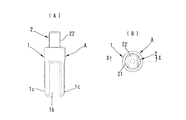
図1〜図13は、この発明の第1実施の形態を示す。この実施の形態の回転ダンパAは、特に図4〜図13に示すように、ケーシング1、ロータ2、ピストン3及び弁体4を主な構成要素としている。なお、図1〜図9においては、ダンパAがその軸線(この軸線は、ケーシング1の軸線であり、ロータ2の回転中心線でもある。)を上下方向に向けて配置されている。そこで、回転ダンパAの各構成については、上下を用いて説明することとする。回転ダンパAは、水平方向又は他の方向に向けて配置してもよい。
The best mode for carrying out the present invention will be described below with reference to the drawings.
1 to 13 show a first embodiment of the present invention. The rotary damper A of this embodiment mainly includes a casing 1, a rotor 2, a piston 3, and a valve body 4 as shown in FIGS. 1 to 9, the damper A is disposed with its axis line (this axis line being the axis line of the casing 1 and the rotation center line of the rotor 2) facing up and down. Therefore, each configuration of the rotary damper A will be described using the upper and lower sides. The rotary damper A may be arranged in the horizontal direction or in another direction.

ケーシング1は、断面円形の金属製の筒体からなるものであり、その内部が収容孔11になっている。収容孔11は、その上端部に開口部1dを有し、下端部が底部1aによって閉じられている。   The casing 1 is made of a metal cylinder having a circular cross section, and the inside thereof is an accommodation hole 11. The accommodation hole 11 has an opening 1d at its upper end, and the lower end is closed by the bottom 1a.

ケーシング1の周壁部には、一対の幅広平坦部1b,1b及び一対の幅狭平坦部1c,1cが形成されている。両平坦部1b,1cは、ケーシング1の上端から所定の同一距離だけ下側へ離れた箇所からケーシング1の下端まで延びている。収容孔11のうちの両平坦部1b,1cが形成された部分が、摺動孔部12になっている。   A pair of wide flat portions 1 b and 1 b and a pair of narrow flat portions 1 c and 1 c are formed on the peripheral wall portion of the casing 1. Both flat portions 1 b and 1 c extend from a position away from the upper end of the casing 1 by a predetermined distance to the lower end of the casing 1. A portion of the accommodation hole 11 where the flat portions 1 b and 1 c are formed is a sliding hole portion 12.

一対の幅広平坦部1b,1bは、ケーシング1の軸線と平行に延びており、ケーシング1の周方向へ180°離れて配置されている。つまり、一対の幅広平坦部1b,1bは、ケーシング1の軸線を挟んで互いに対向するように配置されている。幅広平坦部1b,1bが形成されることにより、摺動孔部12の内周面には、ケーシング1の軸線と平行に延びる第1摺動面13,13が形成されている。 The pair of wide flat portions 1 b and 1 b extend in parallel with the axis of the casing 1 and are disposed 180 degrees apart in the circumferential direction of the casing 1. That is, the pair of wide flat portions 1b and 1b are arranged so as to face each other with the axis of the casing 1 interposed therebetween. By forming the wide flat portions 1 b and 1 b, first sliding surfaces 13 and 13 extending in parallel with the axis of the casing 1 are formed on the inner peripheral surface of the sliding hole portion 12.

一対の幅狭平坦部1c,1cは、ケーシング1の軸線と平行に延びており、ケーシング1の周方向へ180°離れて配置されている。しかも、一対の幅狭平坦部1c,1cは、一対の幅広平坦部1b,1bに対してケーシング1の周方向へ90°離れて配置されている。この結果、幅広平坦部1bと幅狭平坦部1cが、ケーシング1の周方向へ90°毎に交互に配置されている。幅狭平坦部1cは、その幅が幅広平坦部1bの幅より狭くなっている。幅狭平坦部1c,1cが形成されることにより、摺動孔部12の内周面には、ケーシング1の軸線と平行に延びる第2摺動面14,14が形成されている。 The pair of narrow flat portions 1 c and 1 c extend in parallel with the axis of the casing 1 and are disposed 180 degrees apart in the circumferential direction of the casing 1. In addition, the pair of narrow flat portions 1c and 1c are disposed 90 ° away from the pair of wide flat portions 1b and 1b in the circumferential direction of the casing 1. As a result, the wide flat portions 1b and the narrow flat portions 1c are alternately arranged in the circumferential direction of the casing 1 every 90 °. The narrow flat portion 1c is narrower than the wide flat portion 1b. By forming the narrow flat portions 1 c and 1 c, second sliding surfaces 14 and 14 extending in parallel with the axis of the casing 1 are formed on the inner peripheral surface of the sliding hole portion 12.

摺動孔部12の内周面に第1摺動面13,13及び第2摺動面14,14が形成されることにより、摺動孔部12の断面形状が、第1摺動面13に沿う方向を長手方向とし、第2摺動面14に沿う方向を短手方向とする断面略長方形の長孔状に形成されている。しかも、摺動孔部12の4つの角部は、ケーシング1の軸線を曲率中心とする円弧面によって構成されている。 By forming the first sliding surfaces 13 and 13 and the second sliding surfaces 14 and 14 on the inner peripheral surface of the sliding hole portion 12, the sectional shape of the sliding hole portion 12 is changed to the first sliding surface 13. The longitudinal direction is defined as a long direction, and the direction along the second sliding surface 14 is defined as a short direction. In addition, the four corners of the sliding hole 12 are formed by arcuate surfaces with the axis of the casing 1 as the center of curvature.

一対の幅広平坦部1b,1b及び一対の幅狭平坦部1c,1cは、例えば次のようにして形成することができる。すなわち、摺動孔部12と同一の断面形状を有する芯金(図示せず)を収容孔11に挿入する。その後、ケーシング1の周壁部をプレスして芯金の第1摺動面13,13に対応する平坦面に押し付ける。それによって幅広平坦部1b,1bを形成する。次にケーシング1の周壁部をプレスして芯金の第2摺動面14,14に対応する平坦面に押し付ける。それによって、幅狭平坦部1cを形成する。幅広平坦部1b及び幅狭平坦部1cの形成順序は、上記と逆にしてもよく、両者の形成を同時に行ってもよい。   The pair of wide flat portions 1b, 1b and the pair of narrow flat portions 1c, 1c can be formed as follows, for example. That is, a metal core (not shown) having the same cross-sectional shape as the sliding hole 12 is inserted into the accommodation hole 11. Then, the surrounding wall part of the casing 1 is pressed and pressed on the flat surface corresponding to the 1st sliding surfaces 13 and 13 of a metal core. Thereby, the wide flat portions 1b and 1b are formed. Next, the peripheral wall portion of the casing 1 is pressed and pressed against the flat surface corresponding to the second sliding surfaces 14 and 14 of the core metal. Thereby, a narrow flat portion 1c is formed. The order of forming the wide flat portion 1b and the narrow flat portion 1c may be reversed from the above, or both may be formed simultaneously.

ロータ2は、断面円形の嵌合軸部21を有している。嵌合軸部21は、収容孔11の内径と同一の外径を有しており、収容孔11の開口部1d側の端部に収容孔11の軸線(ケーシング1の軸線)を中心として回転可能に嵌合されている。これにより、ロータ2がケーシング1に回転可能に支持されている。嵌合軸部21の外周面と収容孔11の内周面との間は、Oリング等のシール部材51によってシールされている。なお、嵌合軸部21が収容孔11に嵌合された後、ケーシング1の周壁部の上端部が径方向内側へ向かって折り返されることにより、嵌合軸部21がケーシング1にストップリング52を介して上方へ抜け止めされている。   The rotor 2 has a fitting shaft portion 21 having a circular cross section. The fitting shaft portion 21 has the same outer diameter as the inner diameter of the accommodation hole 11, and rotates around the axis of the accommodation hole 11 (the axis of the casing 1) at the end of the accommodation hole 11 on the opening 1 d side. It can be fitted. Thereby, the rotor 2 is rotatably supported by the casing 1. A space between the outer peripheral surface of the fitting shaft portion 21 and the inner peripheral surface of the accommodation hole 11 is sealed by a seal member 51 such as an O-ring. Note that after the fitting shaft portion 21 is fitted into the receiving hole 11, the upper end portion of the peripheral wall portion of the casing 1 is folded back radially inward, so that the fitting shaft portion 21 is attached to the casing 1 in the stop ring 52. It is prevented from coming off through

嵌合軸部21の上端面には、連結軸部22が嵌合軸部21と一体に形成されている。連結軸部22は、ケーシング1から上方へ突出させられている。連結軸部2は、非円形に形成されており、建物の柱や便器本体等の躯体(図示せず)と、扉や便蓋等の回転体(図示せず)とのいずれか一方に回転不能に連結される。躯体と回転体とのいずれか他方には、ケーシング1が回転不能に連結される。この実施の形態では、ケーシング1が便器本体に連結され、連結軸部22が便蓋に連結されている。したがって、便蓋が回転すると、ロータ2がケーシング1に対して回転する。   A connecting shaft portion 22 is formed integrally with the fitting shaft portion 21 on the upper end surface of the fitting shaft portion 21. The connecting shaft portion 22 protrudes upward from the casing 1. The connecting shaft portion 2 is formed in a non-circular shape, and rotates in either one of a housing (not shown) such as a building pillar or a toilet body, and a rotating body (not shown) such as a door or a toilet lid. Linked impossible. The casing 1 is non-rotatably connected to the other of the casing and the rotating body. In this embodiment, the casing 1 is connected to the toilet body, and the connecting shaft portion 22 is connected to the toilet lid. Therefore, when the toilet lid rotates, the rotor 2 rotates relative to the casing 1.

ロータ2は、便蓋が閉位置に位置すると、図1に示す初期位置に位置し、便蓋が開位置に位置すると、図3に示す最大回転位置に位置する。ただし、ロータ2の最大回転角度は、初期位置と最大回転位置との間の角度より若干大きい角度に設定されており、ロータ2は、初期位置から最大回転位置側へ向かう方向(便蓋が閉位置から開位置へ向かう方向であり、図1(B)〜図3(B)において反時計方向;以下、開方向という。)へは最大回転位置を越えて若干の角度(例えば5°程度)だけ回転可能であり、最大回転位置から初期位置側へ向かう方向(便蓋が開位置から閉位置へ向かう方向であり、図1(B)〜図3(B)において時計方向;以下、閉方向という。)へは初期位置を越えて若干の角度(例えば5°程度)だけ回転可能である。   The rotor 2 is located at the initial position shown in FIG. 1 when the toilet lid is located at the closed position, and is located at the maximum rotation position shown in FIG. 3 when the toilet lid is located at the open position. However, the maximum rotation angle of the rotor 2 is set to be slightly larger than the angle between the initial position and the maximum rotation position, and the rotor 2 is directed from the initial position toward the maximum rotation position (the toilet lid is closed). It is a direction from the position to the open position, and in FIG. 1 (B) to FIG. 3 (B), the counterclockwise direction; hereinafter referred to as the open direction) exceeds the maximum rotation position by a slight angle (for example, about 5 °). Direction from the maximum rotational position to the initial position side (the direction in which the toilet lid is directed from the open position to the closed position, clockwise in FIGS. 1B to 3B); Can be rotated by a slight angle (for example, about 5 °) beyond the initial position.

嵌合軸部21の下端面には、雄ねじ部23が嵌合軸部21と一体に形成されている。雄ねじ部23は、その軸線を嵌合軸部21の軸線と一致させて配置されている。雄ねじ部23は、複数条のねじを有している。複数条のねじは、ねじのリード角を大きくするために形成されている。リード角を大きくする必要がない場合には、1条のねじを形成してもよい。   A male thread portion 23 is formed integrally with the fitting shaft portion 21 on the lower end surface of the fitting shaft portion 21. The male screw portion 23 is arranged with its axis line coincident with the axis line of the fitting shaft portion 21. The male screw portion 23 has a plurality of threads. The plurality of screws are formed to increase the lead angle of the screw. If there is no need to increase the lead angle, a single thread may be formed.

雄ねじ部23の下端面には、小径軸部24が雄ねじ部23と一体に形成されている。小径軸部24は、その軸線を雄ねじ部23の軸線と一致させて配置されている。小径軸部24の外径は、雄ねじ部23の谷の径より小径になっている。小径軸部24の外径は、雄ねじ部23のねじの谷の径と同一にしてもよい。   A small-diameter shaft portion 24 is formed integrally with the male screw portion 23 on the lower end surface of the male screw portion 23. The small-diameter shaft portion 24 is disposed with its axis line aligned with the axis line of the male screw portion 23. The outer diameter of the small-diameter shaft portion 24 is smaller than the diameter of the valley of the male screw portion 23. The outer diameter of the small diameter shaft portion 24 may be the same as the diameter of the thread valley of the male screw portion 23.

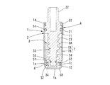
収容孔11のうちのロータ2の嵌合軸部21と底部1aとの間の部分、つまり摺動孔部12には、ピストン3が収容されている。これにより、収容孔11の内部が、嵌合軸部21とピストン3との間の第1の室6Aと、ピストン3と底部1aとの間の第2の室6Bとに区分されている。第1及び第2室6A,6B内を含む、嵌合軸部21と底部1aとの間の収容孔11の内部空間には、粘性流体等の流体が収容されている。   The piston 3 is accommodated in the portion between the fitting shaft portion 21 and the bottom portion 1 a of the rotor 2 in the accommodation hole 11, that is, the sliding hole portion 12. Thereby, the inside of the accommodation hole 11 is divided into a first chamber 6A between the fitting shaft portion 21 and the piston 3 and a second chamber 6B between the piston 3 and the bottom portion 1a. A fluid such as a viscous fluid is accommodated in the internal space of the accommodation hole 11 between the fitting shaft portion 21 and the bottom portion 1a, including the first and second chambers 6A and 6B.

ピストン3は、その外周面の断面形状が摺動孔部12の内周面と同一の断面形状になるように形成されており、摺動孔部12に上下方向(ケーシング1の軸線方向)へ摺動可能に、かつ回転不能に収容されている。したがって、ピストン3の外周面には、一対の第1摺動面13,13に対応する第1平面部31,31が形成されるとともに、一対の第2摺動面14,14に対応する第2平面部32,32が形成されている。第1及び第2摺動面13,14は、ピストン3の上端面から下端面まで延びている。第1及び第2平面部31,32が第1及び第2摺動面13,14にそれぞれ面接触することにより、ピストン3のケーシング1に対する回転が阻止されている。   The piston 3 is formed so that the cross-sectional shape of the outer peripheral surface thereof is the same cross-sectional shape as the inner peripheral surface of the sliding hole portion 12, and the sliding hole portion 12 extends in the vertical direction (the axial direction of the casing 1). It is slidably and non-rotatably accommodated. Accordingly, the first flat surface portions 31, 31 corresponding to the pair of first sliding surfaces 13, 13 are formed on the outer peripheral surface of the piston 3, and the first planar portions 31, 31 corresponding to the pair of second sliding surfaces 14, 14 are formed. Two plane portions 32, 32 are formed. The first and second sliding surfaces 13 and 14 extend from the upper end surface of the piston 3 to the lower end surface. The first and second flat portions 31 and 32 are in surface contact with the first and second sliding surfaces 13 and 14, respectively, so that the rotation of the piston 3 with respect to the casing 1 is prevented.

ピストン3には、その軸線上を上端面から下端面まで延びる雌ねじ部33が形成されている。この雌ねじ部33には、ロータ2の雄ねじ部23が螺合されている。したがって、ロータ2が回転すると、ピストン3が上下方向へ移動する。この場合、ピストン3は、ロータ2が開方向へ回転すると上方へ移動し、ロータ2が閉方向へ回転すると下方へ移動する。これから明らかなように、この回転ダンパAにおいては、雄ねじ部23及び雌ねじ部33により、ピストン3をロータ2の回転に追随して移動させる移動手段が構成されている。   The piston 3 is formed with a female thread portion 33 extending on the axis from the upper end surface to the lower end surface. The male screw portion 23 of the rotor 2 is screwed into the female screw portion 33. Therefore, when the rotor 2 rotates, the piston 3 moves in the vertical direction. In this case, the piston 3 moves upward when the rotor 2 rotates in the opening direction, and moves downward when the rotor 2 rotates in the closing direction. As is clear from this, in the rotary damper A, the male screw portion 23 and the female screw portion 33 constitute moving means for moving the piston 3 following the rotation of the rotor 2.

ピストン3は、ロータ2が最大回転位置に回転すると、図6及び図7に示す上限位置(第1の位置)に位置し、ロータ2が初期位置に回転すると、図4及び図9に示す下限位置(第2の位置)に位置する。ただし、ピストン3は、ロータ2が初期位置と最大回転位置との間の角度より若干大きい角度だけ回転可能であることに対応して、上限位置を超えて若干の距離だけ上方へ移動可能であり、下限位置を越えて若干の距離だけ下方へ移動可能である。   The piston 3 is located at the upper limit position (first position) shown in FIGS. 6 and 7 when the rotor 2 rotates to the maximum rotation position, and when the rotor 2 rotates to the initial position, the lower limit shown in FIGS. It is located at the position (second position). However, the piston 3 can move upward by a slight distance beyond the upper limit position, corresponding to the fact that the rotor 2 can be rotated by an angle slightly larger than the angle between the initial position and the maximum rotational position. It is possible to move downward by a small distance beyond the lower limit position.

ピストン3の下端面には、支持筒部34が形成されている。この支持筒部34の内径は、ロータ2の小径軸部24の外径と同一に設定されている。支持筒部34には、小径軸部24が回転可能に、かつ摺動可能に挿入されている。支持筒部34の内周面と小径軸部24の外周面との間は、Oリング等のシール部材53によってシールされている。   A support cylinder portion 34 is formed on the lower end surface of the piston 3. The inner diameter of the support cylinder portion 34 is set to be the same as the outer diameter of the small diameter shaft portion 24 of the rotor 2. The small diameter shaft portion 24 is inserted into the support cylinder portion 34 so as to be rotatable and slidable. A space between the inner peripheral surface of the support cylinder portion 34 and the outer peripheral surface of the small diameter shaft portion 24 is sealed by a seal member 53 such as an O-ring.

図4〜図9に示すように、ピストン3が上方へ移動すると、第1の室6Aの内部容積が減少し、第2の室6Bの内部容積が増大する。この結果、第1の室6A内の流体が第2の室6Bへ流入しようとする。逆に、ピストン3が下方へ移動すると、第1の室6Aの内部容積が増大し、第2の室6Bの内部容積が減少する。この結果、第2の室6B内の流体が第1の室6Aに流入しようとする。   As shown in FIGS. 4 to 9, when the piston 3 moves upward, the internal volume of the first chamber 6A decreases and the internal volume of the second chamber 6B increases. As a result, the fluid in the first chamber 6A tends to flow into the second chamber 6B. Conversely, when the piston 3 moves downward, the internal volume of the first chamber 6A increases and the internal volume of the second chamber 6B decreases. As a result, the fluid in the second chamber 6B tends to flow into the first chamber 6A.

流体が第1の室6Aと第2の室6Bとの間を流通することができるようにするために、第1の室6Aと第2の室6Bと間には、それらを連通させる連通路7が設けられている。連通路7は、ケーシング1の摺動孔部12の内周面に形成された第1連通溝7Aと、ピストン3の外周面に形成された連通溝7Bとによって構成されている。 In order to allow fluid to flow between the first chamber 6A and the second chamber 6B, a communication path for communicating them between the first chamber 6A and the second chamber 6B. 7 is provided. The communication path 7 is configured by a first communication groove 7 </ b> A formed on the inner peripheral surface of the sliding hole portion 12 of the casing 1 and a communication groove 7 </ b> B formed on the outer peripheral surface of the piston 3.

第1連通溝7Aは、幅狭平坦部1cの幅方向(ケーシング1の周方向)の中央部をケーシング1の径方向外側へ向かって突出させることにより、第2摺動面14に形成されている。なお、第1連通溝7Aを形成するための幅狭平坦部1cの突出量は、当該突出部の外面のうちの最も外側に位置する部分がケーシング1の外周面を構成する円弧面に接するように、その大きさが設定されている。   7 A of 1st communicating grooves are formed in the 2nd sliding face 14 by making the center part of the width direction (circumferential direction of the casing 1) of the narrow flat part 1c protrude toward the radial direction outer side of the casing 1. Yes. The protruding amount of the narrow flat portion 1c for forming the first communication groove 7A is such that the outermost portion of the outer surface of the protruding portion is in contact with the arc surface constituting the outer peripheral surface of the casing 1. The size is set.

第1連通溝7Aは、その幅が第2摺動面14の幅より狭くなっており、第2摺動面14の幅方向の中央部に配置されている。第1連通溝7Aの上端部は、図4〜図9に示すように、第2摺動面14の上端部とほぼ同一位置に配置されており、第1の室6Aと常時連通している。一方、第1連通溝7Aの下端部は、図4及び図9に示すように、下限位置に位置しているピストン3の下端面より所定距離だけ上方に位置するように配置されている。第1連通溝7Aの下端部は、後述するように、第2の室6Bに対しピストン3及び弁体4により連通状態と遮断状態とに切り換えられる。 The first communication groove 7 </ b> A has a width narrower than the width of the second sliding surface 14, and is disposed at the center in the width direction of the second sliding surface 14. As shown in FIGS. 4 to 9, the upper end portion of the first communication groove 7 </ b> A is disposed at substantially the same position as the upper end portion of the second sliding surface 14, and is always in communication with the first chamber 6 </ b> A. . On the other hand, as shown in FIGS. 4 and 9, the lower end portion of the first communication groove 7 </ b> A is disposed so as to be located a predetermined distance above the lower end surface of the piston 3 located at the lower limit position. As will be described later, the lower end portion of the first communication groove 7A is switched between the communication state and the cutoff state with respect to the second chamber 6B by the piston 3 and the valve body 4.

なお、第1連通溝7Aの幅が第2摺動面14の幅より狭くなっているので、第2摺動面14の幅方向の両側部は、平坦面としてそのまま残っている。そして、当該第2摺動面14の両側部にピストン3の第2平面部32の両側部が摺動可能に面接触している。これから明らかなように、第2摺動面14の幅方向の両側部が、内向き平面部であり、第2平面部32の両側部が外向き平面部である。   Since the width of the first communication groove 7A is narrower than the width of the second sliding surface 14, both side portions in the width direction of the second sliding surface 14 remain as flat surfaces. Then, both side portions of the second flat surface portion 32 of the piston 3 are slidably in surface contact with both side portions of the second sliding surface 14. As is clear from this, both side portions of the second sliding surface 14 in the width direction are inward plane portions, and both side portions of the second plane portion 32 are outward plane portions.

第2連通溝7Bは、ピストン3の各第2平面部32にそれぞれ形成されている。ここで、第2平面部32は、断面長方形状をなすピストン3の断面形状における長手方向の両端部に配置されている。したがって、第2連通溝7B,7Bも、ピストン3の外周面のうちの断面形状における長手方向の両端部にそれぞれ配置されている。第2連通溝7Bの長さは、ピストン3の長さと同一であり、第2平面部32の上端から下端まで延びている。第2連通溝7Bの上端は、第1の室6Aに常時連通している。第2連通溝7Bの下端は、後述するように、第2の室6Bに対し弁体4により連通状態と遮断状態とに切り換えられる。   The second communication groove 7 </ b> B is formed in each second flat portion 32 of the piston 3. Here, the 2nd plane part 32 is arrange | positioned at the both ends of the longitudinal direction in the cross-sectional shape of piston 3 which makes cross-sectional rectangular shape. Therefore, the second communication grooves 7 </ b> B and 7 </ b> B are also arranged at both ends in the longitudinal direction in the cross-sectional shape of the outer peripheral surface of the piston 3. The length of the second communication groove 7B is the same as the length of the piston 3, and extends from the upper end to the lower end of the second flat portion 32. The upper end of the second communication groove 7B is always in communication with the first chamber 6A. As will be described later, the lower end of the second communication groove 7B is switched between the communication state and the cutoff state by the valve body 4 with respect to the second chamber 6B.

第2連通溝7Bは、第2平面部32の幅方向の中央部に配置されている。したがって、第2連通溝7Bは、図10に示すように、第1連通溝7Aと対向しており、互いに連通している。この結果、第1連通溝7Aと第2連通溝7Bとによって一つの孔が形成されており、その孔が連通路7になっている。なお、第2連通溝7Bの幅は、第2平面部32の幅より狭くなっているが、第2連通溝7Bの幅は、第1連通溝7Aの幅と同一にしてもよく、第1連通溝7Aの幅より狭くしてもよい。 The second communication groove 7 </ b> B is disposed in the center portion in the width direction of the second plane portion 32. Accordingly, the second communication groove 7B faces the first communication groove 7A and communicates with each other as shown in FIG. As a result, one hole is formed by the first communication groove 7 </ b> A and the second communication groove 7 </ b> B, and the hole serves as the communication path 7. Although the width of the second communication groove 7B is narrower than the width of the second flat portion 32, the width of the second communication groove 7B may be the same as the width of the first communication groove 7A. It may be narrower than the width of the communication groove 7A.

ピストン3の支持筒部34には、弁体4がピストン3の軸線方向(ケーシング1の軸線方向)へ開位置と閉位置との間を移動可能に設けられている。すなわち、支持筒部34の下端部には、係止突出部35が形成されている。係止突出部35は、断面長円状をなしており、その長手方向を摺動孔部12の長手方向と直交する方向に向けて配置されている。   The valve body 4 is provided on the support cylinder portion 34 of the piston 3 so as to be movable between an open position and a closed position in the axial direction of the piston 3 (the axial direction of the casing 1). That is, a locking projection 35 is formed at the lower end of the support cylinder 34. The locking projection 35 has an oval cross section and is arranged with its longitudinal direction oriented in a direction perpendicular to the longitudinal direction of the sliding hole portion 12.

弁体4は、リング状に形成されている。弁体4の内部の断面形状は、係止突出部35の断面形状と同一に形成されている。したがって、弁体4には係止突出部35を挿通可能であり、係止突出部35が弁体4を通り抜けると、弁体4の内部には支持筒部34のうちの係止突出部35より上側の部分が挿通される。その状態で弁体4を係止突出部35に対して90°回転させると、弁体4の短手方向が係止突出部35の長手方向と対向するようになる。この結果、弁体4が支持筒部34から下方へ抜け出ようとすると、弁体4の短手方向の両端部が係止突出部35の長手方向の両端部に突き当たる。これによって、弁体4が支持筒部34から下方へ抜け出ることが阻止されている。   The valve body 4 is formed in a ring shape. The cross-sectional shape inside the valve body 4 is the same as the cross-sectional shape of the locking projection 35. Therefore, the locking projection 35 can be inserted into the valve body 4, and when the locking projection 35 passes through the valve body 4, the locking projection 35 of the support cylinder portion 34 is formed inside the valve body 4. The upper part is inserted. When the valve body 4 is rotated by 90 ° with respect to the locking protrusion 35 in this state, the short side direction of the valve body 4 is opposed to the longitudinal direction of the locking protrusion 35. As a result, when the valve body 4 tries to come out from the support cylinder portion 34, both ends in the short direction of the valve body 4 abut against both ends in the longitudinal direction of the locking projection 35. As a result, the valve body 4 is prevented from coming out of the support cylinder portion 34 downward.

弁体4は、その外部の断面形状が摺動孔部12の断面形状と同一に形成されている。したがって、弁体4は、摺動孔部12に挿脱可能であり、係止突出部35を挿通した後、90°回転させた状態で摺動孔部12に挿入されている。この結果、弁体4がケーシング1の摺動孔部12に回動不能に、かつ摺動可能に嵌合されている。   The valve body 4 has an external cross-sectional shape that is the same as the cross-sectional shape of the sliding hole portion 12. Therefore, the valve body 4 can be inserted into and removed from the sliding hole portion 12, and is inserted into the sliding hole portion 12 while being rotated by 90 ° after being inserted through the locking projection 35. As a result, the valve body 4 is fitted in the sliding hole portion 12 of the casing 1 so as not to rotate but to be slidable.

弁体4の厚さ(ケーシング1の軸線方向の寸法)は、ピストン3の下端面と係止突出部35の上面との間の距離より薄くなっている。したがって、弁体4は、ピストン3の下端面と係止突出部35の上面との間の距離と弁体4の厚さとの差の分だけ上下方向へ移動可能である。弁体4は、ピストン3の下端面に突き当たると、それ以上上方へ移動することができなくなる。このときのピストン3の位置が閉位置である。弁体4は、係止突出部35に突き当たると、それ以上下方へ移動することができなくなる。このときの弁体4の位置が開位置である。   The thickness of the valve body 4 (the dimension of the casing 1 in the axial direction) is thinner than the distance between the lower end surface of the piston 3 and the upper surface of the locking projection 35. Therefore, the valve body 4 is movable in the vertical direction by the difference between the distance between the lower end surface of the piston 3 and the upper surface of the locking projection 35 and the thickness of the valve body 4. When the valve body 4 hits the lower end surface of the piston 3, it cannot move further upward. The position of the piston 3 at this time is a closed position. When the valve body 4 hits the locking projection 35, it cannot move any further downward. The position of the valve body 4 at this time is an open position.

第1の室6Aと第2の室6Bとの間の第1連通溝7A及び第2連通溝7Bによる連通状態及び遮断状態は、ピストン3の位置及び弁体4の位置に応じて次のように変化する。   The communication state and the blocking state by the first communication groove 7A and the second communication groove 7B between the first chamber 6A and the second chamber 6B are as follows according to the position of the piston 3 and the position of the valve body 4. To change.

先ず、弁体4が開位置に位置している場合について説明すると、図4〜図6に示すように、弁体4が開位置に位置している場合には、弁体4の上面とピストン3の下端面との間に環状の隙間S1が形成される。この結果、第2連通溝7Bの下端部が、隙間S1と、弁体4の内周面のうちの断面において長手方向に位置する部分と支持筒部34の外周面との間に形成された隙間S2とを介して第2の室6Bに連通する。したがって、弁体4が開位置に位置している場合には、ピストン3の位置に拘わらず、第1の室6Aと第2の室6Bとが第2連通溝7Bを介して連通している。   First, the case where the valve body 4 is located in the open position will be described. As shown in FIGS. 4 to 6, when the valve body 4 is located in the open position, the upper surface of the valve body 4 and the piston An annular gap S <b> 1 is formed between the lower end surface 3 and the lower end surface 3. As a result, the lower end portion of the second communication groove 7 </ b> B is formed between the gap S <b> 1 and a portion located in the longitudinal direction in the cross section of the inner peripheral surface of the valve body 4 and the outer peripheral surface of the support cylinder portion 34. It communicates with the second chamber 6B via the gap S2. Therefore, when the valve body 4 is located at the open position, the first chamber 6A and the second chamber 6B communicate with each other via the second communication groove 7B regardless of the position of the piston 3. .

第1連通溝7Aと第2の室6Aとの間の連通状態について述べると、弁体4が開位置に位置している場合において、ピストン3が図6に示す上限位置と、弁体4の下面が第1連通溝7Aの下端縁と同一位置に位置した図8に示す中間位置との間に位置しているときには、第1連通溝7Aの下端部が第2の室6Bに直接連通している。したがって、第1の室6Aと第2の室6Bとが第1連通溝7Aを介して連通する。よって、弁体4が開位置に位置している場合において、ピストン3が上限位置と中間位置との間に位置しているときには、第1の室6Aと第2の室6Bとが第1連通溝7Aと第2連通溝7Bとの両者、つまり連通路7全体を介して連通する。   The communication state between the first communication groove 7A and the second chamber 6A will be described. When the valve body 4 is located at the open position, the piston 3 has the upper limit position shown in FIG. When the lower surface is located between the lower end edge of the first communication groove 7A and the intermediate position shown in FIG. 8 located at the same position, the lower end portion of the first communication groove 7A directly communicates with the second chamber 6B. ing. Therefore, the first chamber 6A and the second chamber 6B communicate with each other through the first communication groove 7A. Therefore, when the valve body 4 is located at the open position, when the piston 3 is located between the upper limit position and the intermediate position, the first chamber 6A and the second chamber 6B are in communication with each other. The groove 7A and the second communication groove 7B communicate with each other, that is, through the communication path 7 as a whole.

ピストン3が、中間位置と、ピストン3の下端面が第1連通溝7Aの下端縁と同一位置に位置する遮断位置と間に位置しているときには、第1連通溝7Aの下端部が、第2連通溝7Bの下端部、隙間S1,S2を介して第2の室6Bに連通する。したがって、この場合にも、第1の室6Aと第2の室6Bとが第1連通溝7Aと第2連通溝7Bとの両者を介して連通する。   When the piston 3 is positioned between the intermediate position and the blocking position where the lower end surface of the piston 3 is located at the same position as the lower end edge of the first communication groove 7A, the lower end portion of the first communication groove 7A is The second communication groove 7B communicates with the second chamber 6B via the lower end portion and the gaps S1 and S2. Therefore, also in this case, the first chamber 6A and the second chamber 6B communicate with each other through both the first communication groove 7A and the second communication groove 7B.

ピストン3が遮断位置と下限位置との間に位置しているときには、第1連通溝7Aの下端部がピストン3によって閉じられる。このため、第1の室6Aと第2の室6Bとの間を流れる流体は、一旦第2連通溝7Bの下端部だけを流れることになる。したがって、弁体4が開位置に位置している場合において、ピストン3が遮断位置と下限位置との間に位置しているときには、第1の室6Aと第2の室6Bとが、実質的には第2連通溝7Bだけを介して連通する。   When the piston 3 is positioned between the cutoff position and the lower limit position, the lower end portion of the first communication groove 7A is closed by the piston 3. For this reason, the fluid flowing between the first chamber 6A and the second chamber 6B once flows only in the lower end portion of the second communication groove 7B. Therefore, when the valve body 4 is located at the open position, when the piston 3 is located between the cutoff position and the lower limit position, the first chamber 6A and the second chamber 6B are substantially Is communicated only through the second communication groove 7B.

次に、弁体4が閉位置に位置している場合について述べると、弁体4が閉位置に位置している場合には、隙間S1が閉じられる。この結果、第2連通溝7Bの下端部と第2の室6Bとの間が弁体4によって閉じられる。したがって、弁体4が閉位置に位置している場合には、第2連通溝7Bが第1の室6Aと第2の室6Bとの間の連通に関与することがない。   Next, the case where the valve body 4 is located at the closed position will be described. When the valve body 4 is located at the closed position, the gap S1 is closed. As a result, the valve body 4 closes the space between the lower end of the second communication groove 7B and the second chamber 6B. Therefore, when the valve body 4 is located at the closed position, the second communication groove 7B does not participate in the communication between the first chamber 6A and the second chamber 6B.

第1連通溝7Aは、ピストン3が図7に示す上限位置と図8に示す中間位置(このときの中間位置は、弁体4が開位置に位置しているときのピストン3の中間位置に対し、所定の距離だけ、つまり弁体4の閉位置と開位置との間の距離だけ下側の位置になっている。)との間に位置しているときには、第1連通溝7Aの下端部が第2の室6Bに直接連通している。したがって、弁体4が閉位置に位置している場合において、ピストン7が上限位置と中間位置との間に位置しているときには第1の室6Aと第2の室6Bとが第1連通溝7Aだけを介して連通する。   The first communication groove 7A is formed so that the piston 3 is at the upper limit position shown in FIG. 7 and the intermediate position shown in FIG. On the other hand, the lower end of the first communication groove 7A is positioned at a predetermined distance, that is, a lower position by a distance between the closed position and the open position of the valve body 4). The part communicates directly with the second chamber 6B. Accordingly, when the valve body 4 is located at the closed position, the first chamber 6A and the second chamber 6B are connected to the first communication groove when the piston 7 is located between the upper limit position and the intermediate position. It communicates only through 7A.

ピストン3が中間位置より下方へ移動すると、第1連通溝7Aの下端部が弁体4によって閉じられる。したがって、弁体4が閉位置に位置している場合において、ピストン3が中間位置と下限位置との間に位置しているときには、連通路7全体が弁体4によって遮断されることになり、第1及び第2の室6A,6B内の流体が、連通路7、つまり第1連通溝7A及び第2連通溝7Bを介して流れることがない。第1及び第2の室6A,6B内の流体は、摺動孔部12の内周面と弁体4の外周面との間の摺動に必要な僅かな隙間を通って流れる。このとき、当該僅かな隙間がオリフィスとして機能し、流体が隙間を流れるときに大きな流通抵抗が発生する。この流通抵抗により、ピストン3の下方への移動速度が低速に抑えられ、ひいてはロータ2の閉方向への回転速度が低速に抑えられる。   When the piston 3 moves downward from the intermediate position, the lower end portion of the first communication groove 7A is closed by the valve body 4. Therefore, when the valve body 4 is located at the closed position, when the piston 3 is located between the intermediate position and the lower limit position, the entire communication path 7 is blocked by the valve body 4. The fluid in the first and second chambers 6A and 6B does not flow through the communication path 7, that is, the first communication groove 7A and the second communication groove 7B. The fluid in the first and second chambers 6 </ b> A and 6 </ b> B flows through a slight gap necessary for sliding between the inner peripheral surface of the sliding hole portion 12 and the outer peripheral surface of the valve body 4. At this time, the slight gap functions as an orifice, and a large flow resistance is generated when the fluid flows through the gap. Due to this flow resistance, the moving speed of the piston 3 downward is suppressed to a low speed, and consequently the rotating speed of the rotor 2 in the closing direction is suppressed to a low speed.

上記構成の回転ダンパAにおいて、いま、回転ダンパAが設けられた便器の便蓋が閉位置に位置しているものとする。このときには、ロータ2が初期位置に位置し、ピストン3が図4に示す下限位置に位置し、弁体4が開位置に位置している。便蓋及びロータ2を開方向へ回転させると、ピストン3が下限位置から上方へ移動する。すると、第1の室6A内の流体が連通路7を通って第2の室6Bへ流入しようとする。この流体によって弁体4が下方へ押される。その結果、弁体4が開位置に維持される。   In the rotary damper A having the above configuration, it is assumed that the toilet lid of the toilet bowl provided with the rotary damper A is located at the closed position. At this time, the rotor 2 is located at the initial position, the piston 3 is located at the lower limit position shown in FIG. 4, and the valve body 4 is located at the open position. When the toilet lid and the rotor 2 are rotated in the opening direction, the piston 3 moves upward from the lower limit position. Then, the fluid in the first chamber 6A tries to flow into the second chamber 6B through the communication path 7. The valve body 4 is pushed downward by this fluid. As a result, the valve body 4 is maintained in the open position.

ロータ2が初期位置から開方向へ回転し、それに伴ってピストン3が下限位置から遮断位置まで移動するときには、上記のように、第1の室6Aと第2の室6Bとが実質的には連通路7のうちの第2連通溝7Bだけを介して連通する。したがって、ピストン3は、高速で上方へ移動するが、第1の室6Aと第2の室6Bとが連通路7全体を介して連通する場合よりも若干低速で移動する。よって、ロータ2も高速で回転するが、その回転速度は若干低速回転に抑えられる。 When the rotor 2 rotates in the opening direction from the initial position and the piston 3 moves from the lower limit position to the shut-off position along with the rotation, the first chamber 6A and the second chamber 6B are substantially separated as described above. The communication path 7 communicates only through the second communication groove 7B. Therefore, although the piston 3 moves upward at a high speed, the piston 3 moves at a slightly lower speed than the case where the first chamber 6A and the second chamber 6B communicate with each other through the entire communication path 7. Therefore, although the rotor 2 also rotates at a high speed, the rotation speed is suppressed to a slightly low speed.

ロータ2の開方向への回転に伴ってピストン3が遮断位置と中間位置との間に達すると、第1連通溝7Aの下端部が第2連通溝7B及び隙間S1,S2を介して第2の室6Bに連通する。したがって、第1の室6Aと第2の室6Bとが第1連通溝7A及び第2連通溝7Bを介して連通する。よって、ロータ2が高速回転する。ただし、第1連通溝7Aの下端部が第2の室6Bに第2連通溝7Bを介して連通しているので、第1連通溝7Aの下端部が第2の室6Bに直接連通する場合よりも、流体に対する抵抗が僅かに大きい。したがって、ピストン3が中間位置から上限位置まで移動するときよりもロータ2の回転速度が僅かに低速に抑えられる。   When the piston 3 reaches between the shut-off position and the intermediate position as the rotor 2 rotates in the opening direction, the lower end portion of the first communication groove 7A becomes the second via the second communication groove 7B and the gaps S1 and S2. It communicates with the room 6B. Accordingly, the first chamber 6A and the second chamber 6B communicate with each other through the first communication groove 7A and the second communication groove 7B. Therefore, the rotor 2 rotates at a high speed. However, since the lower end of the first communication groove 7A communicates with the second chamber 6B via the second communication groove 7B, the lower end of the first communication groove 7A communicates directly with the second chamber 6B. Rather than the resistance to the fluid. Therefore, the rotational speed of the rotor 2 can be suppressed slightly lower than when the piston 3 moves from the intermediate position to the upper limit position.

ピストン3が中間位置を上方へ越えると、第1連通溝7Aが第2の室6Bと直接連通する。この結果、第1の室6Aと第2の室6Bとが第2連通溝7B及び第1連通溝7Aの両者を介して連通する。これは、ピストン3が遮断位置と中間位置との間に位置している場合と同様であるが、その場合よりも第1連通溝7Aの下端部が第2の室6Bに直接連通している分だけ流体に対する流通抵抗が小さい。したがって、ピストン3がより高速で上方へ移動することができ、ロータ2がより高速で開方向へ回転することができる。 When the piston 3 crosses the intermediate position upward, the first communication groove 7A communicates directly with the second chamber 6B. As a result, the first chamber 6A and the second chamber 6B communicate with each other via both the second communication groove 7B and the first communication groove 7A. This is similar to the case where the piston 3 is located between the blocking position and the intermediate position, but the lower end portion of the first communication groove 7A communicates directly with the second chamber 6B than in this case. The flow resistance to the fluid is small by the amount. Accordingly, the piston 3 can move upward at a higher speed, and the rotor 2 can rotate in the opening direction at a higher speed.

また、第1の室6Aと第2の室6Bとが、第1連通溝7Aと第2連通溝7Bとの両者を通って流れるときには、両連通溝7A,7Bが互いに対向して一つの連通路7を構成しているので、第1連通溝7Aと第2連通溝7Bとが対向せずに、互いに独立して連通路をそれぞれ構成している場合に比して流通路7の内周面の周長を短くすることができる。換言すれば、第1及び第2連通溝7A,7Bによって構成された一つの連通路7の周長と、第1及び第2連通溝によってそれぞれ構成された二つの連通路の合計周長とを同一にした場合には、一つの連通路7の流路面積(断面積)を二つの連通路の合計の流路面積より大きくすることができ、流路面積の差の分だけ連通路7の流通抵抗を小さくすることができる。よって、ピストン3はより一層高速で移動することができ、ロータ2がさらに高速で回転することができる。便蓋及びロータ2は、開位置に達すると停止する。このときの状態が図6に示されている。 Further, when the first chamber 6A and the second chamber 6B flow through both the first communication groove 7A and the second communication groove 7B, the two communication grooves 7A and 7B face each other to form one communication channel. Since the passage 7 is constituted, the inner periphery of the flow passage 7 is compared with the case where the first communication groove 7A and the second communication groove 7B are not opposed to each other and each of the communication passages is constituted independently. The circumference of the surface can be shortened. In other words, the peripheral length of one communication path 7 constituted by the first and second communication grooves 7A, 7B and the total circumference of the two communication paths respectively constituted by the first and second communication grooves. In the case where they are the same, the flow area (cross-sectional area) of one communication path 7 can be made larger than the total flow area of the two communication paths. Distribution resistance can be reduced. Therefore, the piston 3 can move at a higher speed, and the rotor 2 can rotate at a higher speed. When the toilet lid and the rotor 2 reach the open position, they stop. The state at this time is shown in FIG.

便蓋及びロータ2が開位置から閉回転すると、ピストン3が下方へ移動し、第2の室6B内の流体が連通路7を通って第1の室6Aに流入しようとする。すると、弁体4が流体によって閉位置まで押し上げられる。この結果、第2連通溝7Bが閉じられる。一方、内向き連通路7Aは、上記のように、ピストン3が開位置から中間位置に達するまでの間、第2の室6Bと連通した状態を維持する。したがって、第1の室6Aと第2の室6Bとが実質的に第1連通溝7Aだけを介して連通し、第2の室6B内の流体が第1連通溝7Aを通って第1の室6A内に流入する。ここで、第1連通溝7Aの流通抵抗は、比較的小さいものの、第1連通溝7Aの断面積、つまり流路面積が、第2連通溝7Bの流路面積より小さくなっている。したがって、第1連通溝7Aの流通抵抗は、第2連通溝7Bの流通抵抗より大きい。このため、ピストン3は、比較的高速で下方へ移動することができるが、上方へ移動する場合よりも低速に抑えられる。よって、ロータ2も、開回転時よりも低速で閉回転する。   When the toilet lid and rotor 2 rotate closed from the open position, the piston 3 moves downward, and the fluid in the second chamber 6B attempts to flow into the first chamber 6A through the communication path 7. Then, the valve body 4 is pushed up to the closed position by the fluid. As a result, the second communication groove 7B is closed. On the other hand, as described above, the inward communication path 7A maintains a state of communicating with the second chamber 6B until the piston 3 reaches the intermediate position from the open position. Accordingly, the first chamber 6A and the second chamber 6B are substantially communicated only via the first communication groove 7A, and the fluid in the second chamber 6B passes through the first communication groove 7A and the first It flows into the chamber 6A. Here, although the flow resistance of the first communication groove 7A is relatively small, the cross-sectional area of the first communication groove 7A, that is, the flow path area, is smaller than the flow path area of the second communication groove 7B. Accordingly, the flow resistance of the first communication groove 7A is larger than the flow resistance of the second communication groove 7B. For this reason, the piston 3 can move downward at a relatively high speed, but is suppressed to a lower speed than the case of moving upward. Therefore, the rotor 2 also rotates at a lower speed than during the opening rotation.

ロータ2の閉回転に伴ってピストン3が中間位置を越えると、第1連通溝7Aの下端部と第2の室6Bとの間が弁体4によって遮断される。この結果、第1の室6Aと第2の室6Bとの間が遮断される。このため、第2の室6B内の流体は、摺動孔部12の内周面と弁体4の外周面との間の摺動に必要な僅かな隙間を通って第1の室6A側へ流れる。摺動孔部12の内周面と弁体4の外周面との間を通過した流体は、摺動孔部12の内周面とピストンの外周面との間の隙間(連通路7を含む)を通って第1の室6Aに流入する。ここで、流体が摺動孔部12の内周面と弁体4の外周面との間の隙間を流れるときには、当該隙間がオリフィスとして作用し、大きな流通抵抗を発生させる。この流通抵抗により、ピストン3の下方への移動速度が低速に抑えられ、ひいてはロータ2の閉方向への回転速度が低速に抑えられる。ロータ2が閉位置に達して停止すると、ピストン4が下限位置において停止する。その後、弁体4がその自重によって開位置まで下方へ移動して、回転ダンパAが図4に示す状態になる。   When the piston 3 exceeds the intermediate position as the rotor 2 is closed, the valve body 4 blocks the lower end portion of the first communication groove 7A and the second chamber 6B. As a result, the first chamber 6A and the second chamber 6B are blocked from each other. For this reason, the fluid in the second chamber 6B passes through a slight gap necessary for sliding between the inner peripheral surface of the sliding hole portion 12 and the outer peripheral surface of the valve body 4 to the first chamber 6A side. To flow. The fluid that has passed between the inner peripheral surface of the sliding hole 12 and the outer peripheral surface of the valve body 4 is a gap (including the communication path 7) between the inner peripheral surface of the sliding hole 12 and the outer peripheral surface of the piston. ) And flows into the first chamber 6A. Here, when the fluid flows through the gap between the inner peripheral surface of the sliding hole portion 12 and the outer peripheral surface of the valve body 4, the gap acts as an orifice and generates a large flow resistance. Due to this flow resistance, the moving speed of the piston 3 downward is suppressed to a low speed, and consequently the rotating speed of the rotor 2 in the closing direction is suppressed to a low speed. When the rotor 2 reaches the closed position and stops, the piston 4 stops at the lower limit position. Thereafter, the valve body 4 moves downward to its open position by its own weight, and the rotary damper A is in the state shown in FIG.

上記構成の回転ダンパAにおいては、第1連通溝7A及び第2連通溝7Bによって一つの連通路7が構成されている。この連通路7と、第1連通溝7Aと第2連通溝7Bとが互いに独立した二つの連通路をそれぞれ構成している場合とを比較すると、前者の連通路7と後者の二つの連通路との流通面積を同一にしたものとすると、前者の連通路7の内周面の周長、つまり周方向の長さを、後者の互いに独立した二つの連通路の合計の周長より短くすることができる。換言すれば、前者の連通路の周長と、後者の二つの連通路の合計の周長とを同一にした場合には、前者の連通路の流路面積を後者の二つの連通路の合計の流路面積より大きくすることができる。したがって、この回転ダンパAによれば、連通路7の流通抵抗を小さくすることができ、その分だけ連通路7の流量を大きくすることができる。したがって、ロータ2をより高速で開回転させることができる。しかも、第1及び第2連通溝7A,7Bについては、それぞれの流路面積を大きくする必要がない。したがって、回転ダンパAが大型することがない。   In the rotary damper A configured as described above, one communication path 7 is constituted by the first communication groove 7A and the second communication groove 7B. Comparing this communication path 7 with the case where the first communication groove 7A and the second communication groove 7B constitute two independent communication paths, respectively, the former communication path 7 and the latter two communication paths If the circulation area is the same, the circumferential length of the inner peripheral surface of the former communication path 7, that is, the length in the circumferential direction is made shorter than the total circumferential length of the latter two independent communication paths. be able to. In other words, if the circumference of the former communication path is the same as the total circumference of the latter two communication paths, the flow area of the former communication path is the sum of the latter two communication paths. The flow path area can be made larger. Therefore, according to this rotary damper A, the flow resistance of the communication path 7 can be reduced, and the flow rate of the communication path 7 can be increased accordingly. Therefore, the rotor 2 can be opened and rotated at a higher speed. In addition, the first and second communication grooves 7A and 7B do not need to have a large flow area. Therefore, the rotary damper A does not become large.

また、ロータ2が最大回転位置から閉方向へ回転する場合において、ピストン3が上限位置と下限位置との間に位置しているときには、第2連通溝7Bが弁体4によって閉じられるものの、第1連通溝7Aが第1の室6Aと第2の室6Bとを連通させているので、ピストン3は下方へ比較的高速で回転することができ、ロータ2が比較的高速で閉回転することができる。これにより、ロータ2が最大回転位置から初期位置まで回転するのに要する時間、つまり便蓋が開位置から閉位置まで回転するのに要する時間を短くすることができる。   Further, when the rotor 2 rotates in the closing direction from the maximum rotation position, when the piston 3 is located between the upper limit position and the lower limit position, the second communication groove 7B is closed by the valve body 4, Since the one communication groove 7A communicates the first chamber 6A and the second chamber 6B, the piston 3 can rotate downward at a relatively high speed, and the rotor 2 can be closed and rotated at a relatively high speed. Can do. Thereby, the time required for the rotor 2 to rotate from the maximum rotation position to the initial position, that is, the time required for the toilet lid to rotate from the open position to the closed position can be shortened.

次に、図14〜図18に示すこの発明の第2実施の形態を説明する。なお、この第2実施の形態については、上記第1実施の形態と異なる構成だけを説明することとし、上記第1実施の形態と同様な構成部分には同一符号を付してその説明を省略する。 Next, a second embodiment of the present invention shown in FIGS. 14 to 18 will be described. In the second embodiment, only the configuration different from that of the first embodiment will be described, and the same components as those of the first embodiment will be denoted by the same reference numerals and the description thereof will be omitted. To do.

第2実施の形態の回転ダンパBにおいては、幅狭平坦部1cがケーシング1の下端まで延びている。これに対応して、第2摺動面14及び第1連通溝7Aがケーシング1の下端まで延びている。 In the rotary damper B of the second embodiment, the narrow flat portion 1 c extends to the lower end of the casing 1. Correspondingly, the second sliding surface 14 and the first communication groove 7 </ b> A extend to the lower end of the casing 1.

弁体4の外周面のうちの幅狭平坦部1c,1cと対向する各部分には、閉鎖突出部41がそれぞれ形成されている。閉鎖突出部41は、第1連通溝7Aと同一の形状を有しており、第1連通溝7Aに摺動のための不可避の隙間を除きほとんど隙間無く摺動可能に嵌り込んでいる。これにより、第1連通溝7Aの長手方向の中間部が閉じられている。したがって、第1の室6Aと第2の室6Bとは、第1連通溝7Aだけを介して連通することはない。 A closing projection 41 is formed on each portion of the outer peripheral surface of the valve body 4 facing the narrow flat portions 1c, 1c. The closing protrusion 41 has the same shape as the first communication groove 7A and is slidably fitted into the first communication groove 7A with almost no clearance except for an inevitable clearance for sliding. Thereby, the intermediate part of the longitudinal direction of 7 A of 1st communicating grooves is closed. Accordingly, the first chamber 6A and the second chamber 6B do not communicate with each other only through the first communication groove 7A.

上記構成の回転ダンパBにおいては、弁体4が開位置に位置すると、第1連通溝7A及び第2連通溝7Bが第2の室6Bに隙間S1,S2を介して連通する。この結果、第1及び第2の室6A,6Bが連通路7を介して連通する。
したがって、ロータ2が開回転するときには、ロータ2が高速で回転する。逆に、弁体4が閉位置に位置すると、第1連通溝7A及び第2連通溝7Bが閉じられ、第1及び第2の室6A,6B間が遮断される。したがって、ロータ2が閉回転するときには、ロータ2が低速で回転する。
In the rotary damper B configured as described above, when the valve body 4 is located at the open position, the first communication groove 7A and the second communication groove 7B communicate with the second chamber 6B via the gaps S1 and S2. As a result, the first and second chambers 6A and 6B communicate with each other through the communication path 7.
Therefore, when the rotor 2 rotates open, the rotor 2 rotates at a high speed. On the contrary, when the valve body 4 is located at the closed position, the first communication groove 7A and the second communication groove 7B are closed, and the first and second chambers 6A and 6B are blocked. Therefore, when the rotor 2 rotates in a closed manner, the rotor 2 rotates at a low speed.

なお、この発明は、上記の実施の形態に限定されるものでなく、その要旨を逸脱しない範囲において各種の変形例を採用可能である。
例えば、上記の実施の形態においては、移動手段を雄ねじ部23及び雌ねじ部33によって構成しているが、公知の他の移動手段を採用してもよい。例えば、ロータ2とピストン3との間にカム機構を設けるとともに、ピストン3と底部1aとの間に圧縮コイルばねを設け、カム機構と圧縮コイルばねとにより、ピストン3をロータ2の回転に追随して移動させてもよい。
また、上記の実施の形態においては、ロータ2の下端面に小径軸部24を形成し、この小径軸部24をピストン3の内周面に摺動可能に、かつ回転可能に嵌合させているが、小径軸部24は必ずしも形成する必要がない。
In addition, this invention is not limited to said embodiment, A various modification is employable in the range which does not deviate from the summary.
For example, in the above embodiment, the moving means is constituted by the male screw portion 23 and the female screw portion 33, but other known moving means may be adopted. For example, a cam mechanism is provided between the rotor 2 and the piston 3, and a compression coil spring is provided between the piston 3 and the bottom 1 a, and the piston 3 follows the rotation of the rotor 2 by the cam mechanism and the compression coil spring. And may be moved.
In the above embodiment, the small-diameter shaft portion 24 is formed on the lower end surface of the rotor 2, and the small-diameter shaft portion 24 is slidably and rotatably fitted on the inner peripheral surface of the piston 3. However, the small diameter shaft portion 24 is not necessarily formed.

A 回転ダンパ
B 回転ダンパ
1 ケーシング
1a 底部
1d 開口部
2 ロータ
3 ピストン
4 弁体
6A 第1の室
6B 第2の室
7 連通路
7A 第1連通溝
7B 第2連通溝
12 摺動孔部
23 雄ねじ部(移動手段)
33 雌ねじ部(移動手段)
A rotating damper B rotating damper 1 casing 1a bottom 1d opening 2 rotor 3 piston 4 valve body 6A first chamber 6B second chamber 7 communication path 7A first communicating groove 7B second communicating groove 12 sliding hole 23 male screw (Moving means)
33 Female thread (moving means)

Claims (3)

一端部が開口し、他端部が底部によって閉じられたケーシングと、上記ケーシングに回転可能に設けられたロータと、このロータと上記底部との間の上記ケーシングの内部に摺動可能にかつ回転不能に設けられ、上記底部と上記ロータとの間の上記ケーシングの内部を第1の室と第2の室とに区分するピストンと、このピストンを上記ロータの回転に追随して移動させる移動手段と、上記第1の室と上記第2の室とを連通させる連通路と、この連通路を開閉する弁体とを備え、上記底部と上記ロータとの間に位置する上記ケーシングの内部に流体が充填された回転ダンパにおいて、
上記ケーシングの内周面には第1連通溝が形成され、上記ピストンの外周面には第2連通溝が形成され、上記第1連通溝と上記第2連通溝とが上記ケーシングの径方向に互いに対向して配置され、上記第1及び第2連通溝によって上記連通路が構成されていることを特徴とする回転ダンパ。
A casing having one end opened and the other end closed by a bottom, a rotor rotatably provided in the casing, and a slidable and rotating inside the casing between the rotor and the bottom A piston which is provided in an impossible manner and divides the inside of the casing between the bottom and the rotor into a first chamber and a second chamber, and a moving means for moving the piston following the rotation of the rotor And a communication passage that allows the first chamber and the second chamber to communicate with each other, and a valve body that opens and closes the communication passage, and a fluid is provided inside the casing that is located between the bottom and the rotor. In the rotary damper filled with
A first communication groove is formed on the inner peripheral surface of the casing, a second communication groove is formed on the outer peripheral surface of the piston, and the first communication groove and the second communication groove are arranged in the radial direction of the casing. A rotary damper, wherein the rotary damper is disposed to face each other, and the communication path is constituted by the first and second communication grooves.
上記ピストンが第1の位置と第2の位置との間を摺動可能であり、上記第1連通溝は、上記ピストンが上記第1の位置とこの第1の位置と上記第2の位置との間の所定の中間位置との間に位置しているときには開状態に維持され、上記ピストンが上記中間位置と上記第2の位置との間に位置しているときには上記弁体によって閉じられ、上記第2連通溝は、上記ピストンが上記第1の位置から上記第2の位置まで移動するときには、上記弁体によって閉じられ、上記ピストンが上記第2の位置から上記第1の位置まで移動するときには、開状態に維持されることを特徴とする請求項1に記載の回転ダンパ。 The piston is slidable between a first position and a second position, and the first communication groove is configured so that the piston has the first position, the first position, and the second position. When the piston is located between the intermediate position and the second position, the valve body is closed when the piston is located between the intermediate position and the second position. The second communication groove is closed by the valve body when the piston moves from the first position to the second position, and the piston moves from the second position to the first position. 2. The rotary damper according to claim 1, wherein the rotary damper is maintained in an open state. 上記ピストンが第1の位置と第2の位置との間を摺動可能であり、上記第1連通溝及び上記第2連通溝は、上記ピストンが上記第1の位置から上記第2の位置に向かって移動するときには、上記弁体によって閉じられ、上記ピストンが上記第2の位置から上記第1の位置に向かって移動するときには、開状態に維持されることを特徴とする請求項1に記載の回転ダンパ。 The piston is slidable between a first position and a second position, and the first communication groove and the second communication groove are arranged so that the piston moves from the first position to the second position. 2. The valve body according to claim 1, wherein the valve body is closed when moving toward the first position, and is kept open when the piston moves from the second position toward the first position. Rotating damper.
JP2013053326A 2013-03-15 2013-03-15 Rotary damper Pending JP2014178011A (en)

Priority Applications (1)

Application Number Priority Date Filing Date Title
JP2013053326A JP2014178011A (en) 2013-03-15 2013-03-15 Rotary damper

Applications Claiming Priority (1)

Application Number Priority Date Filing Date Title
JP2013053326A JP2014178011A (en) 2013-03-15 2013-03-15 Rotary damper

Publications (1)

Publication Number Publication Date
JP2014178011A true JP2014178011A (en) 2014-09-25

Family

ID=51698158

Family Applications (1)

Application Number Title Priority Date Filing Date
JP2013053326A Pending JP2014178011A (en) 2013-03-15 2013-03-15 Rotary damper

Country Status (1)

Country Link
JP (1) JP2014178011A (en)

Cited By (1)

* Cited by examiner, † Cited by third party
Publication number Priority date Publication date Assignee Title
CN111561538A (en) * 2020-06-11 2020-08-21 蔡燕辉 Rotary damper

Cited By (1)

* Cited by examiner, † Cited by third party
Publication number Priority date Publication date Assignee Title
CN111561538A (en) * 2020-06-11 2020-08-21 蔡燕辉 Rotary damper

Similar Documents

Publication Publication Date Title
WO2015098952A1 (en) Double eccentric valve
JP6656846B2 (en) Flow path switching valve and seal member
WO2017204000A1 (en) Rotary damper
EP3636952A1 (en) Rotary damper comprising simple self-supporting mechanism
TW201839317A (en) Gas switch device comprising a valve group, a rotating lever and a stop lever and capable of being applied in natural gas and barreled liquefied gas
EP2664818B1 (en) Damper device
JP2014178011A (en) Rotary damper
JP2012211628A (en) Damper device
JP6166068B2 (en) Rotating damper
TWM464562U (en) Cold-hot water balance valve structure and cold-hot water valve having the cold-hot water balance valve structure
JP5033245B2 (en) Rotating damper
WO2012133388A1 (en) Rotary damper
JP4825242B2 (en) Rotating damper
JP2019090522A (en) Flow channel changeover valve
JP2007218364A (en) Spool valve
JP7346132B2 (en) fluid damper device
JP2018204618A (en) Rotary damper and toilet seat device
CN203239824U (en) Oscillating type buffer with blade valve
JP2015227719A (en) Simple self-supporting mechanism
JP2007085503A (en) Motion control device
US20190110649A1 (en) Rotary buffer capable of adjusting damping
JP2019210653A (en) Flow path switching mechanism
JP6218420B2 (en) Speed control device
CN215980895U (en) Regulating valve
JP5214403B2 (en) Rotating damper