JP2014177996A - Fastening part structure and processing method for screw hole burring part - Google Patents
Fastening part structure and processing method for screw hole burring part Download PDFInfo
- Publication number
- JP2014177996A JP2014177996A JP2013052547A JP2013052547A JP2014177996A JP 2014177996 A JP2014177996 A JP 2014177996A JP 2013052547 A JP2013052547 A JP 2013052547A JP 2013052547 A JP2013052547 A JP 2013052547A JP 2014177996 A JP2014177996 A JP 2014177996A
- Authority
- JP
- Japan
- Prior art keywords
- screw
- burring
- fastening
- bead
- corrugated
- Prior art date
- Legal status (The legal status is an assumption and is not a legal conclusion. Google has not performed a legal analysis and makes no representation as to the accuracy of the status listed.)
- Abandoned
Links
- 238000003672 processing method Methods 0.000 title claims description 7
- 239000000463 material Substances 0.000 claims abstract description 175
- 238000012545 processing Methods 0.000 claims abstract description 30
- 238000000034 method Methods 0.000 claims description 64
- 239000011324 bead Substances 0.000 claims description 59
- 230000008569 process Effects 0.000 claims description 51
- 239000002184 metal Substances 0.000 claims description 18
- 229910052751 metal Inorganic materials 0.000 claims description 18
- 238000003780 insertion Methods 0.000 claims description 11
- 230000037431 insertion Effects 0.000 claims description 11
- 230000002093 peripheral effect Effects 0.000 claims description 7
- 238000005553 drilling Methods 0.000 claims description 5
- 230000008719 thickening Effects 0.000 claims description 4
- 239000007769 metal material Substances 0.000 abstract description 8
- 238000010079 rubber tapping Methods 0.000 description 22
- 229910000831 Steel Inorganic materials 0.000 description 12
- 238000003825 pressing Methods 0.000 description 12
- 239000010959 steel Substances 0.000 description 12
- 238000010586 diagram Methods 0.000 description 8
- 238000005452 bending Methods 0.000 description 5
- 238000004049 embossing Methods 0.000 description 3
- 238000004519 manufacturing process Methods 0.000 description 3
- 238000005096 rolling process Methods 0.000 description 3
- 230000015572 biosynthetic process Effects 0.000 description 2
- 238000005520 cutting process Methods 0.000 description 2
- 230000006378 damage Effects 0.000 description 2
- 230000007423 decrease Effects 0.000 description 2
- 230000000694 effects Effects 0.000 description 2
- 238000003754 machining Methods 0.000 description 2
- 238000000465 moulding Methods 0.000 description 2
- 230000035515 penetration Effects 0.000 description 2
- 239000000047 product Substances 0.000 description 2
- 230000002787 reinforcement Effects 0.000 description 2
- 238000010008 shearing Methods 0.000 description 2
- 230000009466 transformation Effects 0.000 description 2
- 229910001369 Brass Inorganic materials 0.000 description 1
- 241001391944 Commicarpus scandens Species 0.000 description 1
- NIPNSKYNPDTRPC-UHFFFAOYSA-N N-[2-oxo-2-(2,4,6,7-tetrahydrotriazolo[4,5-c]pyridin-5-yl)ethyl]-2-[[3-(trifluoromethoxy)phenyl]methylamino]pyrimidine-5-carboxamide Chemical compound O=C(CNC(=O)C=1C=NC(=NC=1)NCC1=CC(=CC=C1)OC(F)(F)F)N1CC2=C(CC1)NN=N2 NIPNSKYNPDTRPC-UHFFFAOYSA-N 0.000 description 1
- 230000009471 action Effects 0.000 description 1
- 229910052782 aluminium Inorganic materials 0.000 description 1
- XAGFODPZIPBFFR-UHFFFAOYSA-N aluminium Chemical compound [Al] XAGFODPZIPBFFR-UHFFFAOYSA-N 0.000 description 1
- 239000010951 brass Substances 0.000 description 1
- 239000010960 cold rolled steel Substances 0.000 description 1
- 239000013065 commercial product Substances 0.000 description 1
- 238000007796 conventional method Methods 0.000 description 1
- 238000005336 cracking Methods 0.000 description 1
- 230000000593 degrading effect Effects 0.000 description 1
- 238000006073 displacement reaction Methods 0.000 description 1
- 238000009863 impact test Methods 0.000 description 1
- 230000007246 mechanism Effects 0.000 description 1
- 238000007747 plating Methods 0.000 description 1
- 239000000843 powder Substances 0.000 description 1
- 230000000750 progressive effect Effects 0.000 description 1
- 230000009467 reduction Effects 0.000 description 1
- 239000012779 reinforcing material Substances 0.000 description 1
- 239000011347 resin Substances 0.000 description 1
- 229920005989 resin Polymers 0.000 description 1
- 230000000452 restraining effect Effects 0.000 description 1
- 239000010935 stainless steel Substances 0.000 description 1
- 229910001220 stainless steel Inorganic materials 0.000 description 1
- 238000012360 testing method Methods 0.000 description 1
- 238000012546 transfer Methods 0.000 description 1
- 238000005406 washing Methods 0.000 description 1
Images


Classifications
-
- F—MECHANICAL ENGINEERING; LIGHTING; HEATING; WEAPONS; BLASTING
- F16—ENGINEERING ELEMENTS AND UNITS; GENERAL MEASURES FOR PRODUCING AND MAINTAINING EFFECTIVE FUNCTIONING OF MACHINES OR INSTALLATIONS; THERMAL INSULATION IN GENERAL
- F16B—DEVICES FOR FASTENING OR SECURING CONSTRUCTIONAL ELEMENTS OR MACHINE PARTS TOGETHER, e.g. NAILS, BOLTS, CIRCLIPS, CLAMPS, CLIPS OR WEDGES; JOINTS OR JOINTING
- F16B37/00—Nuts or like thread-engaging members
- F16B37/02—Nuts or like thread-engaging members made of thin sheet material
-
- F—MECHANICAL ENGINEERING; LIGHTING; HEATING; WEAPONS; BLASTING
- F16—ENGINEERING ELEMENTS AND UNITS; GENERAL MEASURES FOR PRODUCING AND MAINTAINING EFFECTIVE FUNCTIONING OF MACHINES OR INSTALLATIONS; THERMAL INSULATION IN GENERAL
- F16B—DEVICES FOR FASTENING OR SECURING CONSTRUCTIONAL ELEMENTS OR MACHINE PARTS TOGETHER, e.g. NAILS, BOLTS, CIRCLIPS, CLAMPS, CLIPS OR WEDGES; JOINTS OR JOINTING
- F16B37/00—Nuts or like thread-engaging members
- F16B37/005—Nuts or like thread-engaging members into which threads are cut during screwing
Landscapes
- Engineering & Computer Science (AREA)
- General Engineering & Computer Science (AREA)
- Mechanical Engineering (AREA)
- Connection Of Plates (AREA)
- Shaping Metal By Deep-Drawing, Or The Like (AREA)
Abstract
Description
本発明は、金属板金にビスを締結するビス穴のビス締結部構造及びネジ穴バーリング加工方法に関する。特に、ビス穴周囲にバーリング加工を施し、ビス締結の補強を行う薄板金属材の締結部構造、及び、締結部構造におけるネジ穴バーリング部の加工方法に関する。 The present invention relates to a screw fastening portion structure of a screw hole for fastening a screw to a metal sheet metal and a screw hole burring method. In particular, the present invention relates to a fastening portion structure of a thin metal material that performs burring processing around a screw hole and reinforces screw fastening, and a processing method of a screw hole burring portion in the fastening portion structure.
従来、金属材料で形成される締結材である板材と締結材と同様の金属製板材や樹脂材料からなる被締結材をビスにより固定する構成は一般的である。装置などの生産や市場での部品交換などにおいて、ビスでの固定は取り付け取り外しが容易であるので、よく用いられる。ある程度の厚みのある締結材、被締結材においては、締結材及び被締結材に設けられたビスと係合するビス穴にビスを係合することによって締結材と被締結材は固定される。 2. Description of the Related Art Conventionally, a structure in which a plate material that is a fastening material formed of a metal material and a material to be fastened made of a metal plate material or a resin material similar to the fastening material are fixed with screws. Fixing with screws is easy to install and remove in the production of devices and parts replacement in the market, etc., so it is often used. In a fastening material having a certain degree of thickness and a material to be fastened, the fastening material and the material to be fastened are fixed by engaging a screw with a screw hole that engages with a screw provided on the fastening material and the material to be fastened.
一方、締結材である金属板などの板材の板厚が1mm程度と薄い場合であっても、薄板用のビスにより被締結材を締結材に対し確実に固定する必要がある。このために、ビスと係合する締結材のビス穴部にバーリング加工を施し、ビス係合部であるビス穴胴部高さ(以下、「バーリング高さ」という。)を確保する。このバーリング加工により、ビスのネジ山と締結材のビス穴の当接箇所を単に締結材にネジ穴加工したときの厚みよりもビス係合部を増加させる方法が知られている。 On the other hand, even when the thickness of a plate material such as a metal plate, which is a fastening material, is as thin as about 1 mm, it is necessary to securely fix the material to be fastened to the fastening material with a thin plate screw. For this purpose, burring processing is performed on the screw hole portion of the fastening material that engages with the screw, and the screw hole body portion height (hereinafter referred to as “burring height”) that is the screw engaging portion is secured. There is known a method of increasing the screw engaging portion by the burring process rather than the thickness when the screw thread of the screw and the screw hole of the fastening material are simply machined into the fastening material.
特許文献1では、塑性変形によりネジを形成するタップ下穴の最先端部近傍内周面を内方に膨出させて、肉厚増加部を形成し、該肉厚増加部内径を前記タップ下穴内径より小径としたことを特徴とする、タップ下穴バーリング加工構造が提案されている。
In
このような技術的構成とすることにより、有効ネジ山の引掛り率を100%とし、締付トルクを高め、締結部の強度が従来方式に比し増大する、としている。 By adopting such a technical configuration, the catch rate of the effective thread is set to 100%, the tightening torque is increased, and the strength of the fastening portion is increased as compared with the conventional method.
上記の様なバーリング加工を行うと加工工数が増える為、特許文献2では、締結材に行うバーリング加工における加工費および加工工数を低減し、効率を向上させるために、解決手段として、以下の方法が提案されている。 In order to reduce the processing cost and the processing man-hour in the burring processing performed on the fastening material and to improve the efficiency, the following method is used as a solution in order to increase the processing man-hour when performing the burring process as described above. Has been proposed.
従来、二工程により行われていた、ねじ下穴等、小径ピアスバーリング以外のバーリング成形を一工程で成形した予備絞りを有する予備絞り付き絞り抜きバーリング加工方法である。即ち、特許文献2には、この予備絞り付き絞り抜きバーリング加工における予備絞り付き絞り抜きバーリングポンチ形状及び予備絞り付き絞り抜きを使用した加工を行うことを特徴とするバーリング加工方法が示されている。
This is a draw-out burring method with a pre-drawer having a pre-drawer formed by a single step of burring forming other than the small-diameter piercing burring, such as a screw pilot hole, which has been conventionally performed in two steps. That is,
更に、特許文献3は、エンボス部の成形とピアス穴加工とを一工程で行うことを前提としつつも、パッドやストリッパー等のいわゆるワーク押さえ機構を不要にした構造を提供せんとしている。つまり、ダイ穴が形成されたボタンダイを有する下型とピアスポンチを有する上型との協働により、パネルに対するエンボス部の成形とそのエンボス部相当部でのピアス穴の加工とを一工程にて行うものである。また、その際に、上型の下降動作に基づいてピアスポンチとダイ穴とのせん断作用によりピアス穴の加工を先行して行い、そのピアス穴の加工よりも遅れて下型と上型のエンボス成形面同士がピアス穴の周囲を加圧拘束することでエンボス部を成形するように成したものが知られている。
Furthermore,
ここで、特許文献1では、タップ下穴の最先端部近傍内周面を内方に膨出させて、ネジ締結部増加形状を形成したバーリング加工を設けている。このバーリング内径はタップ下穴径とし、メートル並目ネジ若しくはセルフタッピングビスにより被締結材を締結する事ができる。
Here, in
また、バーリング加工を施す目的としては、ネジ締結力を確保するために、ネジ山の当接箇所を、できるだけ多く設けることである。このためには、バーリング高さを高くする必要があり、これによりバーリング内径部とバーリング外形部で形成される肉厚を薄くせざるを得ないが、この肉厚は、ネジの侵入により破壊されない前提で設定される。 Further, the purpose of performing the burring process is to provide as many screw thread contact portions as possible in order to secure the screw fastening force. For this purpose, it is necessary to increase the burring height, and thus the thickness formed by the burring inner diameter portion and the burring outer shape portion must be reduced, but this thickness is not destroyed by the penetration of the screw. It is set on the assumption.
しかしながら、締結材の板厚が薄くなればなる程、バーリング内径部とバーリング外形部で形成される肉厚が十分に確保できず、薄肉部がネジにより破壊されてしまい、十分な締結力を発生させることができなくなる可能性がある。しかしまた、バーリング加工を行うと、絞り部根元でR形状の逃げ形状が生じる。このために、段付きネジを使用する場合には段付ねじの段差を十分に受ける座面が確保できない場合もある。そのために、段付き部を増やすと、ネジ部全体が大きくなり、その影響で装置全体が大きくなってしまうという問題がある。 However, as the plate thickness of the fastening material decreases, the wall thickness formed by the burring inner diameter portion and the burring outer shape portion cannot be sufficiently secured, and the thin wall portion is broken by the screw, generating sufficient fastening force. There is a possibility that it will not be possible. However, when burring is performed, an R-shaped relief shape is generated at the base of the narrowed portion. For this reason, when using a stepped screw, the seat surface which receives the level | step difference of a stepped screw fully may not be ensured. Therefore, when the number of stepped portions is increased, there is a problem that the entire screw portion becomes large and the entire device becomes large due to the influence.
また、特許文献2においては、一工程でバーリング加工ができる点で優れているが、バーリングの曲げ円周部にはR形状ができているので、特許文献1と同様に段付ねじを利用する場合には、座面の設定に余裕を持つように留意する必要がある。また、バーリング高さと抜き落とされたスクラップ材の大きさには、バーリング高さを高くすればスクラップの量は少なくなるという、一定の関係がある。しかし、この加工方法ではバーリング高さを高くしようとすると、バーリング部にクラックが入ってしまう虞がある。
Moreover, in
更には、スクラップ材が生じないようにして、バーリング部の増肉加工は行う事ができない為、適用する板厚の厚みを薄板に適用するには限界があるという課題がある。 Furthermore, since it is impossible to increase the thickness of the burring portion without generating scrap material, there is a problem that there is a limit to applying the thickness of the plate thickness to be applied to a thin plate.
更に、特許文献3においては、エンボスの形成とピアス穴加工を一工程で達成する面で優れ、ピアス穴にタップ加工を行う事ができ、エンボス部で補強できる。しかしながら、板厚が薄い場合、ネジ締結という観点から見ると、ネジ締結後に、ネジ部にせん断力が加わると、薄板であるために締結するネジが板金の変形によって倒れやすい事がある。
Furthermore, in
また、ネジの掛かり量が少ないため強度不足となり、破断しやすく必要な締結トルクを得る事ができないという問題がある。 Further, since the amount of the screw is small, the strength is insufficient, and there is a problem that it is easy to break and a necessary fastening torque cannot be obtained.
また、平面側から見ると、円形状のエンボス加工であり、エンボス縁の段差部ではクランク状の断面形状となるので曲げ強度が向上する。しかしながら、中央部のピアス穴部の補強には至っていない。 Further, when viewed from the plane side, it is circular embossing, and the stepped portion of the embossed edge has a crank-like cross-sectional shape, so that the bending strength is improved. However, the pierced hole at the center has not been reinforced.
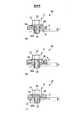
ここで、従来のバーリング加工を施した薄板に、ネジ締結する際の一例について述べる。図1、図2は、薄板鋼板である薄板板金の従来のバーリング形状にネジを締結する締結部構造90の様子を示す実験結果を示している。図1(a)、(b)、(c)は、従来のネジ締結状態を示す断面図であり、ネジを締結した場合の締結部の変形破壊の様子を示した図である。また、図2は、従来のネジ締結強度を示す断面写真と、ネジ締結トルク曲線図である。
Here, an example of screw fastening to a conventional thin plate subjected to burring processing will be described. 1 and 2 show experimental results showing a state of a
先ず、図1(a)〜(c)に示す締結部構造90を説明する。
First, the
ビス3は、ビス頭31とネジ部であるネジ足32を有している。ビス頭31の頭頂部33には十字ドライバ等でビス3を回転させるための十字穴形状(不図示)が形成されている。ネジ足32の外周面にはネジ山である雄ネジ32aが形成されている。ビス頭31にはビス頭31の一部で、ネジ足32側に配置され直径が大とされたフランジ形状で形成されたビスツバ部34が一体に形成されている。ビスツバ部34は被締結材2とツバ接触部2aにて接する。
The
薄板状の鋼材などの金属板である締結材1はバーリング加工により締結材1の一部をバーリング高さ(h)に絞り上げたバーリング部1´を有している。
The fastening
図2は、従来のバーリング加工を施した薄板鋼板である締結材1にタッピングビス3を締結した際の、ねじ込みトルク状態を示すグラフと断面写真である。
FIG. 2 is a graph and a cross-sectional photograph showing a screwing torque state when a tapping
図2の一番左にある断面写真によると締結材1のバーリング部1´(図2(a):バーリング加工後)には雌ネジ部は切られていない。この締結材1を用いて、被締結材2はタッピングビス3によって、係合部に雌ネジが切られながら締結する(図2(b):1.3N・m締結)。グラフに示す様に、タッピングビス3をねじ込んでいくとねじトルクが変化する。破断トルクを超えた締結部は係合部の内部の雌ネジが破断している(図2(c):破断後)。
According to the leftmost cross-sectional photograph in FIG. 2, the female thread portion is not cut in the
更に、説明すると図2の中央の断面図写真(図2(b):1.3N・m締結)で示しているように、締結材1のバーリング部1´にタッピングビス3を締め付けると、バーリング部1´の先端端部が外側に漏斗状(funnel)に拡がるような付勢力が加わる。本例に用いられているような薄板板金では特に引張り強度に弱く展延し易くなるため、セルフタップの形成が少なくなるという問題点が有り、最大破断トルクも少なくなる。それと共に、図2の右側の断面図写真(図2(c):破断後)に示しているようにバーリング部1´の雌ネジのネジ山が先に削り取られて破断してしまうという状況になりやすくなる。
Further, as shown in the cross-sectional photograph at the center of FIG. 2 (FIG. 2B: 1.3 N · m fastening), when the tapping
図1のように、締結トルクを高めるために考案され市販されている、皿状のツバ付きネジ3(例えば、日東精工社の商品名RSタイト)を使用する場合は、絞り部分より外側に締結力が加わり、薄板板金である締結材1はネジ締結力によって変形を生じる。このとき、図1(a)、(b)、(c)の矢印Aで示したような締結材1の変形が生じる。このような締結部構造90の場合には、締結材1と被締結材2の変形を防止し、再締結する際に安定した締結力を得るという機能を十分に満足できないという問題がある。
As shown in FIG. 1, when using a plate-shaped flanged screw 3 (for example, the product name “RS tight” manufactured by Nitto Seiko Co., Ltd.) that has been devised and marketed to increase the fastening torque, it is fastened outside the throttle part. A force is applied, and the
なお、図2の締結材1は、板厚0.6mmのSECC−SD材料(電気亜鉛メッキ鋼板)を用いている。締結材1にはメートル並目ネジM3のタッピングビス(tapping screw)用内径寸法の下穴を直径2.78mmにて設定したバーリング加工を施してある。本例では、日東精工社の商品名RSタイト(特開平11−247817号公報参照)、M3(メートル並目ネジ)サイズを装着した態様を示す。図2の中央の断面写真(図2(b):1.3N・m締結)では、正規の締結トルクである、ネジ山破断トルクの70%の締結力1.3N・mによって締結された状態である。既に、締結材1と被締結材2が、ビス3のビスツバ部34の内側においてネジ頭部側に、ネジ締結力によってジャッキアップ変形が生じている事がわかる。
2 is made of SECC-SD material (electrogalvanized steel sheet) having a thickness of 0.6 mm. The
つまり、薄板板金で強い締結力を得るためのネジを採用することは、締結材1と被締結材2双方の部材を変形させてしまい、平面精度を狂わせてしまう。そのため、特に再分解組立てを行うような個所には採用できないという問題がある。
That is, adopting a screw for obtaining a strong fastening force with a thin sheet metal deforms both the
上記の理由からやむなく、バーリング部内面にネジ部を形成した後、皿状ツバ形状のビスツバ部を有さない、ネジ頭部締結面が平面の、バインドネジやナベ小ネジを用いれば、締結力が弱まり、変形を防げる。しかし、大きなスラスト荷重が掛る装置に採用する場合は、振動試験や落下衝撃試験などの状況でネジが緩み易くなる。これによって、スラスト方向に締結材と被締結材とのズレが生じてしまう為、装置の性能を狂わせてしまう虞がある。この締結力低下を防止し等価の剛性を得るためには、その不足分のネジの本数を増やす必要が生じる。このためネジを多く使用するため、組立てやメンテナンス、或いは分解リサイクル等の作業で時間が掛ってしまうという問題があった。上記従来例によると、実験結果等から薄板板金である締結材にビスを適正な締結力を持って締結させるためには次の解決すべき課題がある。 For the above reasons, after forming the screw part on the inner surface of the burring part, it is possible to use a binding screw or pan head screw that has a flat screw head fastening surface and does not have a countersunk screw shaped screw part. Will weaken and prevent deformation. However, when it is used in a device that is subject to a large thrust load, the screw is likely to loosen in situations such as vibration tests and drop impact tests. As a result, a displacement between the fastening material and the material to be fastened occurs in the thrust direction, and there is a possibility that the performance of the apparatus is upset. In order to prevent this reduction in fastening force and obtain equivalent rigidity, it is necessary to increase the number of screws that are insufficient. For this reason, since many screws are used, there has been a problem that it takes time to assemble, maintain, disassemble and recycle. According to the above conventional example, there are the following problems to be solved in order to fasten the screw with an appropriate fastening force to the fastening material that is a thin sheet metal from the experimental result and the like.
ネジ山32aとビス穴との当接係合箇所をできるだけ多く設けるため、バーリング高さ(h)を高くする必要がある。然しながら、体積一定の原理により、バーリング高さ(h)を高くすると、バーリング内径部とバーリング外形部で形成される肉厚が薄くなる。従って、ビス3のネジ山32aのバーリング部1´の薄肉部への侵入により薄肉部が破壊されるなどして、ネジ3の締結力が確保できなくなる。
The burring height (h) needs to be increased in order to provide as many contact engagement points between the
さらに、締結材1の板厚が薄くなればなるほど、バーリング内径部とバーリング外形部で形成されるバーリング部1´の肉厚が十分に確保できず、ビス3の締結力が低下する。更に、締結材1のネジ締結面も、ビスツバ34外周からネジ足32に向かってビス頭31の下面が傾斜を持つ皿形状のフランジ形状のビスツバ部を有するビスを用いると、ネジ締結力によるジャッキアップが生じ締結面が膨らんでしまう。
Furthermore, as the plate thickness of the
そこで、本発明の目的は、薄い板金材料にバーリング加工を施し、所定の締結トルクでネジ締結できる締結部構造及びネジ穴バーリング部加工方法を提供することである。 Accordingly, an object of the present invention is to provide a fastening portion structure and a screw hole burring portion machining method capable of performing burring on a thin sheet metal material and screw fastening with a predetermined fastening torque.
上記目的は本発明に係る締結部構造及び締結部構造におけるネジ穴バーリング部の加工方法にて達成される。本発明の一態様によれば、ビス頭とネジ部を有するビスと、前記ビスにより締結される締結材と、前記ビスと前記締結材の間に挟まれて前記締結材に締結される被締結材と、を有し、前記ビスが螺合される前記締結材のビス穴は、バーリング加工されたビス挿入方向に突出した略円筒形状のバーリング部にて形成される締結部構造において、前記略円筒形状のバーリング部は、前記バーリング加工された前記締結材が周方向に折り畳まれ、且つ、円筒形状長手方向に沿って延在した波形状バーリングとされることを特徴とする締結部構造が提供される。 The above object is achieved by the fastening part structure and the method for machining the screw hole burring part in the fastening part structure according to the present invention. According to one aspect of the present invention, a screw having a screw head and a screw portion, a fastening material fastened by the screw, and a fastened to be fastened to the fastening material by being sandwiched between the screw and the fastening material In the fastening portion structure formed by a substantially cylindrical burring portion protruding in a burring screw insertion direction, the screw hole of the fastening material into which the screw is screwed is provided. A cylindrical burring part is provided with a fastening part structure in which the burring-processed fastening material is folded in the circumferential direction and is a wave-shaped burring extending along the cylindrical longitudinal direction. Is done.
本発明の他の態様によれば、ビス頭とネジ部を有するビスと、前記ビスにより締結される締結材と、前記ビスと前記締結材の間に挟まれて前記締結材に締結される被締結材と、を有し、前記ビスが螺合される前記締結材のビス穴は、バーリング加工されたビス挿入方向に突出した略円筒形状のバーリング部にて形成される締結部構造におけるネジ穴バーリング部の加工方法であって、前記締結材を構成する薄板材に対し、半球状の絞り加工を行い、次に、穴あけ、放射型ビード形成加工を行い、次に絞り寄せ増肉加工を行い、次に平面化加工を行って波形状バーリングを形成することを特徴とする締結部構造のネジ穴バーリング部の加工方法が提供される。 According to another aspect of the present invention, a screw having a screw head and a screw portion, a fastening material fastened by the screw, and a workpiece sandwiched between the screw and the fastening material and fastened to the fastening material. A screw hole in the fastening portion structure formed by a substantially cylindrical burring portion projecting in a burring-processed screw insertion direction. A method for processing a burring part, which is a hemispherical drawing process for the thin plate material constituting the fastening material, followed by drilling, radial bead forming process, and then drawing and increasing the thickness. Then, a processing method of the screw hole burring portion of the fastening portion structure is provided, in which the corrugated burring is formed by performing planarization processing.
本発明によれば、薄い板金材料にバーリング加工を施し、所定の締結トルクでネジ締結できる。 According to the present invention, a thin sheet metal material can be subjected to burring and can be screwed with a predetermined fastening torque.
以下、本発明に係る締結部構造を図面に則して更に詳しく説明する。 Hereinafter, the fastening part structure according to the present invention will be described in more detail with reference to the drawings.
実施例1
図3(a)、(b)(c)、及び、図4(a)、(b)は、本発明のバーリング加工に係る締結部構造の一実施例を示した図である。
Example 1
3 (a), (b), (c), and FIGS. 4 (a), (b) are views showing an embodiment of a fastening part structure according to the burring process of the present invention.
図に示す様に、本発明に係る締結部構造90において、ビス3と締結材1に挟まれてビス3が締結材1に螺合することによって被締結材2が締結材1に締結されている。
As shown in the figure, in the
ビス3は、ビス頭31及び、ネジ足32を有している。本実施例では、ビス頭31のネジ足32側に直径が大とされた、ビスツバ部34が一体に形成されている。ビスツバ部34はビス頭31の一部を形成し、ビス頭31の座面部31aを形成している。
The
図3(b)に示す様に、ビス3のビス足32の一端のビス頭31の頭頂部33に十字ドライバ等でビス3を回転させるための十字穴形状33aが形成されている。
As shown in FIG. 3B, a
図3(c)に示す様にネジ足32の外周面にはネジ山である雄ネジ32aが形成されている。上述のように、ビス頭31の座面部31aを構成するビスツバ部34は、ビス頭31のネジ足32側に配置されており、ネジ足32の長手方向に対して直交する径でビス頭31部分よりも大きい径を持つフランジ形状となっている。
As shown in FIG. 3C, a
鋼材などの薄板金属である被締結材2はビス穴21を有する。締結材1は、鋼材などの薄板金属とされ、本明細書では説明の便宜のために一側、即ち、図3(a)にて締結材1の上側面を表側Baとし、その反対側面を裏側Bbとする。締結材1はバーリング加工により締結材1の一部をバーリング高さhに締結材1の表側Baから裏側Bbに絞り上げた波形状バーリング11を有している。
The
ここで、締結材1は薄板板金の電気亜鉛メッキ鋼板(JIS記号SECC−SD)、一般圧延鋼板である冷間圧延鋼板(JIS記号SPCC)に鍍金加工して用いる。或いはハイテン材と呼ばれる、高張力鋼板(JIS G3134,JIS3135 SPFH,SPFC,HTSS JFE社−CA材等)を用いても同様である。板厚(t)は0.4mmを例にしているが、実施時の範囲はM3ネジ(メートル並目ネジのサイズ)の場合は0.3mm以上、0.8mm未満程度である。
Here, the
なお、材料は市場で汎用材として利用されるものは、SPCCでは0.1mmの段階であるが、電気亜鉛メッキ鋼板の一般の市販品で、特殊設定ではない場合、板厚(t)0.6mmの上は0.8mmとなる。他方、高成形性ステンレス鋼、真鍮、アルミニウム等、他の材料にも同様に適用する事は可能である。 The material used as a general-purpose material in the market is at the stage of 0.1 mm in SPCC, but it is a general commercial product of electrogalvanized steel sheet, and the thickness (t) is 0. 6mm above is 0.8mm. On the other hand, it can be similarly applied to other materials such as high formability stainless steel, brass and aluminum.
板厚(t)0.8mmに於いては、通常のバーリング加工によってM3タップ加工(JIS/ISOメートル並目ネジ)により雌ネジ形成する事が可能である。よって、実質的にはM3ネジを適用する場合は、板厚(t)0.3mm〜0.6mmの範囲となる。 When the plate thickness (t) is 0.8 mm, female threads can be formed by M3 tapping (JIS / ISO metric coarse thread) by ordinary burring. Therefore, when the M3 screw is applied substantially, the thickness (t) is in the range of 0.3 mm to 0.6 mm.
然しながら、詳細は後述するが、本発明の波形状バーリング11は、ネジ締結強度を薄板板金において達成するための手段であるので、M3に限定される事は無く、メートル細目ネジ、或いはM1等の精密小ねじからM4,M5等の大きなネジにも適用する事は可能である。 However, although the details will be described later, the corrugated burring 11 of the present invention is a means for achieving the screw fastening strength in the thin sheet metal, and is not limited to M3, such as a metric fine screw or M1. It is possible to apply from precision small screws to large screws such as M4 and M5.
本実施例では、板厚0.4mmの締結材1には、M3用サイズの波形状バーリング11が設けられ、被締結材2である板材の中央部にビス穴21を開けたものを波形状バーリング11と合致するように、配置し、ビス3を用いて締結する。ビス3は六角十字穴ツバ付きのメートル並目タッピンネジであり日東精工社製のM3のRSタイト(商品名)を用いている。
In the present embodiment, the
(締結部構造)
締結材1の波形状バーリング11について更に詳しく説明する。
(Fastening structure)
The corrugated burring 11 of the
図3(a)、図4(b)に示す様に、締結材1の裏側Bbには締結材平面部1aの中心部に波形状バーリング11が設けられている。波形状バーリング11の中心部は雌ネジ穴12とされる。波形状バーリング11は、締結材平面部1aから高さhにてビス挿入方向である、略円筒形状長手方向に且つ雌ネジ穴12の半径方向外方へと雌ネジ穴12の内周面11cの外周囲を囲包するようにして略円筒形状としてビス挿入方向へ延在して形成されている。延在した波形状バーリング11は、ビス3のネジ足部32の周囲にそって谷折り11aと山折り11bが交互に連続して繰り返されている。ビス挿入方向に形成された谷折り11aの谷部11a´と山折り11bの山部11b´の内周部(即ち、ネジ穴11c)と、ビス3のネジ部32aが係合する。波形状バーリング11の谷部11a´から山部11b´までの距離、つまりネジ穴バーリング部における増肉されたビス3との係合部の肉厚(h11)(図3(c))は0.6〜1.2mmとされる。
As shown in FIGS. 3 (a) and 4 (b), a corrugated burring 11 is provided on the back side Bb of the
ビス3が締結されると、ネジ頭31の被締結材2との接触側には、フランジ状の皿形状のビスツバ部34が形成されており、最も直径外側の当接面であるツバ接触部2aによって、被締結材2に接触する。このビス3によって被締結材2が締結材平面部1aに締結される。そのため、通常のネジよりもビスツバ部34の突出分だけ遠くなるために、緩みにくく、緩みトルクも高くなるという特徴を有している。
When the
波形状バーリング11に、タッピングビスであるビス3のネジ足32のセルフタップ形成部から順次回転締結される事で、波形状バーリング11のネジ穴内径部11cに雌ネジが形成され、同時にビス3が締めつけられていく事によって締結が完了する。
By sequentially rotating and fastening the self-tapping portion of the
(締結材の締結部の構造)
次に、図5〜図8を参照して波形状バーリング加工を施された締結材1について更に説明する。
(Structure of fastening part of fastening material)
Next, the
図5、図6において、締結材1の表側Baから裏側Bbへと突出して形成された中央部のネジ穴12の周囲には概円筒形状の波形状バーリング11が設けられ、波形状バーリング11のネジ穴内径部11cは雌ネジが形成できるような下穴径d11とされている。下穴径d11はビス3のビスネジ部32と同径か、略同一となる径である。波形状バーリング11は円周放射状に10等分された凹凸形状を成していて山部11bと谷部11aとが交互に連続して繰り返される事で、増肉した板厚(肉厚)(h11)となるように折り畳まれている。
5 and 6, a corrugated burring 11 having a substantially cylindrical shape is provided around a
本実施例では、締結材1の板厚(t)は0.4mmであり、円筒内径(d11)はメートル並目ネジM3の切削タップ或いは転造タップの下穴径である2.459mm、或いは、セルフタッピンネジ下穴内径の2.78mmに設定されている。また、内径(d11)と波形状バーリング11の外形の差分の半分に相当する増肉板厚(h11)は0.8mmとしてある。これは、通常のM3バーリングの加工限度とされる0.8mmの板厚と同じである。よって、増肉によって0.8mmを達成すれば、ネジ締結強度は、図2で示したネジ破断トルク2N・mの70%のトルク1.4N・mの締結力を得る事ができた。
In this embodiment, the plate thickness (t) of the
通常ネジの締結力は、破断トルクの70%程度とする事が一般的である。なお、メートル並目ネジM3を適用するバーリング加工の場合で、板厚0.8mmの場合、バーリング下穴直径(d11)は0.9mmであるので体積不変の理由に拠りバーリング高さ(h)は板厚(t)を含めて1.4mmとなる(図5(c))。M3の場合ネジピッチは0.5mmであるから、2.5山のネジ係り量を確保できる。 Usually, the fastening force of a screw is generally about 70% of the breaking torque. In the case of burring processing using a metric coarse screw M3, when the plate thickness is 0.8 mm, the burring pilot hole diameter (d11) is 0.9 mm, so the burring height (h) is based on the reason for volume unchanged. Is 1.4 mm including the plate thickness (t) (FIG. 5C). In the case of M3, since the screw pitch is 0.5 mm, a screw thread amount of 2.5 threads can be secured.
本実施例では板厚0.4mmでバーリングの下穴直径(d11)を0.8mmとして、波形状バーリング11を形成すると、板厚を含めたバーリング高さ(h)は1.6mmとする事ができた。これによってM3ネジ3山のネジ係り量を確保する事ができた。また、ネジのリードが長くなるため、ネジ締結時に加わるトルクを分散でき、バーリングのダメージをより軽減させる事が可能となる他、繰り返しのネジ締結に拠る摩耗を減らす事ができるようになった。 In the present embodiment, when the corrugated burring 11 is formed with a plate thickness of 0.4 mm and a burring pilot hole diameter (d11) of 0.8 mm, the burring height (h) including the plate thickness is set to 1.6 mm. I was able to. As a result, it was possible to secure a screw engagement amount of three M3 screws. In addition, since the lead of the screw becomes long, the torque applied at the time of screw fastening can be dispersed, the damage of the burring can be further reduced, and wear due to repeated screw fastening can be reduced.
他方、電気亜鉛メッキ鋼板等の金属材料で形成された締結材1の板厚(t)0.4mmの薄板材へのM3メートル並目タッピンネジで適正な締結力を得るためのバーリング構成の場合には、薄板材である締結材1に、タップ加工若しくはタッピンネジであるビス3により、波形状バーリング11の円筒内面11cに雌ネジ穴12を形成してある。
On the other hand, in the case of a burring configuration for obtaining an appropriate fastening force with an M3 meter coarse tapping screw to a thin plate material of a plate thickness (t) 0.4 mm of a
本実施例に於いて、締結材1である薄板材の板厚(t)は0.4mmであり、メートル並目ネジのネジ山ピッチ0.5mmとなって約20%範囲内で設定してある。
In this embodiment, the plate thickness (t) of the thin plate material that is the
更に板厚(t)0.3mmの場合は、メートル細目ネジM1ネジピッチ0.2mm〜M3ネジピッチ0.35mm、また、メートル並目ネジではM1ネジピッチ0.25mm〜M3ピッチ0.45mmに適用可能である。 Further, when the plate thickness (t) is 0.3 mm, the metric fine screw M1 screw pitch is 0.2 mm to M3 screw pitch 0.35 mm, and the metric coarse screw is applicable to the M1 screw pitch 0.25 mm to M3 pitch 0.45 mm. is there.
同様にメートル並目ネジM4の場合は、ネジピッチは0.7mmであるので板厚(t)はM2ネジピッチ0.4mm〜M6ネジピッチ1mmまでの範囲で適用可能である。このように、ネジの山谷の差と概ね同等であるネジピッチに定義される、ネジ山高さよりも薄い板厚にも適用可能である。従って、ピッチに適用されるネジのピッチの約±40%の範囲の板厚に適用される。
Similarly, in the case of the metric coarse screw M4, since the screw pitch is 0.7 mm, the plate thickness (t) can be applied in the range of M2 screw pitch 0.4 mm to
(製造方法)
次に、図7、図8を参照して、波形状バーリング11を形成するためのプレス加工工程の詳細を説明する。図7、図8で示すように、本実施例では、締結材1である薄板板金が短冊状板1Aとされ、この短冊状板1Aの締結材平面部1aが順次トランスファーに拠りプレス工程を行う順送金型を用いてバーリング11が形成されるものとして説明する。
(Production method)
Next, with reference to FIG. 7, FIG. 8, the detail of the press work process for forming the waveform burring 11 is demonstrated. As shown in FIGS. 7 and 8, in this embodiment, the thin sheet metal that is the
図7(a)、(b)及び、図8(a)、(b)、(c)は締結部構造の締結材にバーリング加工を施す加工工程を示す図であり、図7(c)〜(e)はバーリングの他の形状の一例を示す断面図である。図7(a)は短冊状板1Aの表側Baから見た斜視図であり、図7(b)は裏側Bbから見た斜視図である。図8(a)は側面図であり、図8(b)は表側Baから見た平面図であり、図8(c)は断面図である。
7 (a), 7 (b), 8 (a), 8 (b), and 8 (c) are diagrams showing processing steps for burring the fastening material of the fastening portion structure. (E) is sectional drawing which shows an example of the other shape of a burring. FIG. 7A is a perspective view seen from the front side Ba of the strip-shaped
図7(a)、(b)、及び、図8(a)、(b)、(c)に於いて、図面左側から右側方向に順次プレス工程が進んでいくように配置し説明する。 7 (a), 7 (b) and 8 (a), 8 (b), 8 (c), description will be made by arranging the pressing process so that the pressing process proceeds sequentially from the left side of the drawing to the right side.
締結材平面部1aに対して、1工程目は、深絞り加工であり、半球状の絞り加工を行い、締結材平面部1aの表側Baから裏側Bbへ凸となる球面絞り1bを形成する。2工程目は、穴あけ、放射型ビード形成加工であり、球面絞り1bに対して中心部にネジ穴となる貫通穴12を開ける。更に、同中心から放射状に半径方向外方向へと延在し、拡がる絞り凹凸形状の絞りビード11´aを形成する。3工程目は、絞り寄せ増肉加工であり、裏側Bbの球面絞り部1bを図7(b)の矢印Cに示す様に貫通穴12の中心部に向かって寄せていく。そして、2工程目で形成した放射状の絞りビード11´aが山谷を形成しながら円筒形状11´bになるように増肉形成していく。放射状の絞りビード11´の放射状部分が折り畳まれて山谷を形成しながら円筒状波形絞り11´bを形成する。4工程目は平面化加工と必要に応じて行なうタップ加工工程であり、球面絞り1bを元の締結材平面部1aと同一の面と成るようにフラットに戻すプレス加工を行う事で、波形状バーリング11が形成されたネジ穴12ができ上がり完成する。
The first step is deep drawing for the
上記の1工程目の球面絞り1bでは締結材1の薄板鋼板などがフラットのままでは加工できない材料を表側Baから裏側Bbに凸な球面1bにする事で材料が塑性変形しやすいようにすると共に、2工程目の絞りビード11´aが形成できるようにしてある。
In the
また、3工程目の波形絞り工程では、表側Baから裏側Bbに凸な球面1bの部分が図7(b)の矢印Cに示す様に、貫通穴12の中央部へ向かって締め付けるように寄せられて行くが、実際には1工程では既定の直径にする事が難しいので、更に工程を増やして対応するのが好適である。
Also, in the third waveform corrugation step, the portion of the
然しながら、工程を増やすと、金型が増えるので波形状バーリング11の山谷の波形の高さh11、つまり波形状バーリングの肉厚は必要な増肉板厚を確保できる最小限度範囲に留めるのが良い。 However, if the number of processes is increased, the number of molds increases, so that the corrugated height h11 of the corrugated burring 11, that is, the thickness of the corrugated burring, should be kept to the minimum range that can ensure the necessary thickness increase. .
また、ビード凹凸形状は、図7(c)の如くコの字の断面形状とする事には限定されず、半円のU字型形状(図7(d))や、V溝型形状(図7(e))に成す事も自由に応用設定可能な範囲である。特に絞り寄せ工程で、曲げ加工が厳しい場合や、絞り加工が厳しい場合はU字形状にして応力を分布させることで材料曲げ割れを防止する事ができる。 The bead uneven shape is not limited to a U-shaped cross-sectional shape as shown in FIG. 7C, but is a semicircular U-shaped shape (FIG. 7D) or a V-groove shape ( The process shown in FIG. 7 (e) is within a range where application settings can be freely made. In particular, when the bending process is severe in the drawing process or when the drawing process is severe, it is possible to prevent material bending cracking by distributing the stress in a U shape.
なお、4工程目では内径のネジ穴12に山谷の波形が残ると、ネジの係り量が実質的に減るので、ネジ山の破断トルクが低下するようになる。従って、ネジ穴12ができるだけ凹凸の無い円になる方が好ましく、そのために内径側に金型による希望の下穴径(d11)に設定した芯軸を入れて外側から締め付けるようにプレスで仕上げ加圧する事が好適である。或いは、ネジ下穴用の内径部の真円度や円筒度を高めるために、プレス加工では内径を僅かに小さく形成し、仕上げにプレス加工によるブローチ加工、シェービング加工等の仕上げ加工を行っても良い。
In the fourth step, if the corrugation of the valley is left in the
最後に、ネジ穴12に転造タップによりネジ山を形成するか、タッピングビスを用いるかは、用途によって判断する。特に、電気的な導通性が要求されるプリント基板のネジ締結の場合は、転造タップに拠りタップ加工を施し、確実なトルク管理ができる事で、電気的接触の接触圧力を確実にする事が可能となる。
Finally, whether to form a screw thread in the
更に、タッピングビス等によるセルフタップの場合に生じる切削粉が導電部に落下しないようにプレス加工後は切粉や油分に対して洗浄等の配慮する事が好適である。 In addition, it is preferable to consider washing and oil with respect to chips and oil after pressing so that cutting powder generated in the case of self-tapping with a tapping screw or the like does not fall on the conductive portion.
以上のように、波形状バーリング加工時に円筒部長手方向に円周を略等分割する凹凸状の折畳み形状である波形絞り11により、円筒部を増肉した波形形状に形成されたバーリングを提供できる。
As described above, it is possible to provide a burring formed in a corrugated shape in which the cylindrical portion is thickened by the
実施例2
次に図9〜図14を参照して、本発明の実施例2について説明する。前述の実施例1では、締結材1の裏側Bbのネジ穴12の周囲に波形状バーリング11を形成したが、本実施例では更にこの波形状バーリング11の周囲に略長方形の放射状のビード4を設けるという点で実施例1と異なる。
Example 2
Next,
本実施例では、金属材料で形成された締結材である薄板材へのネジ締結部において、実施例1に記載した波形状バーリング11の他に、締結材1である薄板材にプレス加工に拠るビード形状である放射型絞りビード4を、雌ネジ穴12中心から同心円上の円周放射状に交互に凹凸となるように形成することを特徴とする。
In the present embodiment, in addition to the corrugated burring 11 described in the first embodiment, the thin plate material that is the
図9(a)、(b)、(c)、及び、図10(a)、(b)は、本実施例を適用した締結材1を示している。締結材平面部1aの裏側Bbの中央には、ビス穴12の周囲に実施例1と同様に波形状バーリング11が設けられている。締結材平面部1aには波形状バーリング11の中心O11と略同心にて中心O11から放射状で、円周を均等に10等分した放射形状絞りビード4が配置されている。この放射形状絞りビード4はビス挿入方向に凹形状にて形成されている。本実施例では、幅4w=0.5mm、深さ4h=0.4mm、長さ4L=1.5〜4mmで、両端部はR形状に成され絞られている。ネジ穴12からの距離ΔL=1mm。この放射形状絞りビード4を追加配備したことで、締結材平面部1aの放射状方向への曲げ強度が強くなるように補強している。これによって、図1、図2の従来の例で示したような、ネジ締結時に生じる平面部のジャッキアップを低減する事となる。
9 (a), (b), (c) and FIGS. 10 (a), (b) show the
実施例1で示したように波形状バーリング11はネジ締結強度が板厚(t)0.4mmでありながら波形状バーリング11の筒状の肉厚(h11)が増肉加工により0.8mm相当に成るので、締結強度が向上する。然し、これに見合う締結材平面部1aの強度は板厚(t)0.4mmのままでは弱いので放射形絞りビード4を設ける。このことで板厚0.8mm相当となるのでバランス良くネジ締結補強ができる事となった。
As shown in Example 1, the corrugated burring 11 has a screw fastening strength of plate thickness (t) of 0.4 mm, but the tubular thickness (h11) of the corrugated burring 11 is equivalent to 0.8 mm by the thickening process. As a result, the fastening strength is improved. However, the strength of the
図11は、本実施例を適用した締結材1と被締結材2をビス3にて締結した状態を示す図であり、図11(a)は表側Baから見た斜視図、図11(b)は裏側Bbから見た斜視図である。図12は、本実施例を適用した締結材1と被締結材2をビス3にて締結した締結部構造90の状態を示す図であり、図12(a)は側面図、図12(b)は表面平面図、図12(c)は一部断面図である。
FIG. 11 is a view showing a state in which the
特に、図12(c)に示す様にネジ3のネジ首35から外側に伸びる皿状斜面の先端である円形のビスツバ部34の被締結材2とのツバ接触部2aの直径dよりも、略長方形の放射形絞りビード4の外径Dである外接円が大きくなるように配備されているので、締結材1が補強されて変形しにくくなるように成されている。
In particular, as shown in FIG. 12 (c), the diameter d of the
(製造方法)
次に、図13、図14を参照して本実施例における波形状バーリング11の加工工程を説明する。本実施例においても、実施例1で示したプレス加工工程と同様に図13(a)、(b)(c)、及び、図14(a)、(b)に於いて、図面左側から右側方向に順次プレス工程が進んでいくものとして説明する。
(Production method)
Next, with reference to FIG. 13, FIG. 14, the process of the waveform burring 11 in a present Example is demonstrated. Also in the present embodiment, in the same manner as the press working step shown in the first embodiment, in FIGS. 13A, 13B, and 14A and 14B, the left side to the right side of the drawing are used. It is assumed that the pressing process proceeds in the direction.
1工程目の球面絞り加工で締結材平面部1aの表側Baから裏側Bbへ凸となる球面絞り1bを形成する。2工程目は、穴あけ、放射型ビード形成加工で波形状バーリング11の加工のための波形状バーリング絞りビード11´を形成する。3工程目は、絞り寄せ増肉加工で波形バーリングを形成する。4工程目は平面化加工と必要に応じて行なうタップ加工工程で波形状バーリング11を、実施例1と同様に加工を進める。
A
本実施例では、更に行う5工程目のビード加工に特徴が有る。即ち、ビス挿入方向に対して凹状となる放射形絞りビード4が波形状バーリング11の周囲に位置するよう追加されている。
The present embodiment is characterized by bead processing in the fifth step to be further performed. That is, a
尚、本実施例では円周を10分割しているが、これに限定されるものではなく、円周3等分、4等分等任意に分割した放射型絞りビード4を形成して補強することも可能である。また、円形状に放射形絞りビード4を形成しているが、円形に限られる事無く、周囲の形状や他の部品配置等を勘案して三角形や四角形などの任意の多角形状や円弧を持つ異形状にすることも可能である。この放射型絞りビードに4よって、締結材1の締結部構造90における強度が増し、ビス締結時のジャッキアップ変形が低減する。
In this embodiment, the circumference is divided into ten parts, but the present invention is not limited to this, and the
実施例3
次に図15〜図18を参照して本発明の実施例3について説明する。
Example 3
Next,
実施例2と異なるのは放射形絞りビード41の凹凸と波形状バーリング11の凹凸が放射状に連続して、円周を同一数で等分割となるように一体的に一致させたビード形状を有してなる薄板材の波形状バーリング11であることが実施例1、2と異なる。
The difference from the second embodiment is that the unevenness of the
図15〜図18は、本実施例を示す図である。図15(a)、(b)、(c)、及び、図16(a)、(b)は、本実施例における締結材1を示す図である。図15(a)は側面図、図15(b)は表側Baから見た平面図、図15(c)は断面図である。図16(a)は表側Baから見た斜視図、図16(b)は裏側Bbから見た斜視図である。更に、図17(a)、(b)、(c)、及び、図18(a)、(b)は、本実施例の締結材1のバーリング11のプレス加工工程を示す図である。図17(a)、(b)、(c)、及び、図18(a)、(b)は、実施例1、2と同様に図面左側から右側方向に順次プレス工程が進んでいくように配置している。図17(a)は側面図、図17(b)は表側Baから見た平面図、図17(c)は断面図である。図18(a)は表側Baから見た斜視図、図18(b)は裏側Bbから見た斜視図である。
15 to 18 are diagrams showing this embodiment. FIGS. 15A, 15B and 15C, and FIGS. 16A and 16B are views showing the
本実施例では、図15、図16に示す様に先ず、金属材料で形成された締結材1の薄板材へ実施例1で示した増肉波形形状バーリング11を設ける。この波形状バーリング11の周囲に実施例2と同様に放射状ビードである放射形絞りビード41を設ける。
In this embodiment, as shown in FIGS. 15 and 16, first, the thickened corrugated burring 11 shown in the
図15、図16に示すように締結材1のネジ穴バーリング部は波形状バーリング11の円周を10等分した波形山部11bと谷部11aとが交互に連続して折り畳まれ、増肉されている状態である。この波形状バーリングは、実施例2と同様にして加工することができる。つまり、図17、図18にて示している絞りビード11´が寄せ集められて形成されたものであるが、この絞りビード11´を長くして、波形状バーリング11が成型された外側にも残った放射形絞りビード41となるように成型したものである。即ち、絞りビード11´と放射形絞りビード41とはプレス工程では同一の加工によって成されたものである。このような連続したビード形状を設けたことによって、バーリング根元の強度は更に高まる。図1、図2で示したネジ締結力によるジャッキアップ変形の特徴であるバーリング根元近傍の変形を防止することを目的としている。本実施例によってバーリング根元の締結材平面部1aは円周方向の補強と、放射状のビードのダブル補強となり、規定の強いトルクの締結力であっても薄板部分が変形しにくい、最も効果的な形状を有する薄板用のバーリングの提供が可能となった。図17乃至図18で示しているプレス工程は実施例2と同様であるが、波形状バーリング11から延びる放射形状絞りビード41の形状が異なる。つまり、波形状バーリング11と連続して放射形状絞りビード41が形成されているため、それぞれの凹凸が一致し、つながっている。
As shown in FIGS. 15 and 16, the threaded hole burring portion of the
簡単に説明すれば、締結材平面部1aに対して、1工程目は、深絞り加工であり、締結材平面部1aの表側Baから裏側Bbへ凸となる半球状の絞り加工を行い、球面絞り1bを形成する。2工程目は、穴あけ、放射型ビード形成加工であり、球面絞り1bに対して中心部にネジ穴となる貫通穴12を開ける。更に同中心から放射状に広がる絞り凹凸状の絞りビード11´a、を形成する。この時、形成される絞りビード11´aは実施例1、2のものよりも長い11´aとする。3工程目は、絞りよせ増肉加工であり、球面絞り部1bを裏側から中心部に寄せていくようにして2工程目で形成した放射状の絞りビード11´aが山谷を形成しながら円筒形状11´bになるように増肉していく。この時、絞りビード11´aの全体が円筒形状11´bを形成せず、絞りビード11´aの一部は絞りビードのまま周囲に残るように形成する。4工程目で平面化加工とタップ加工工程を行い、球面絞り1bをもとの締結材平面部1aと同一の面と成るようにフラットに戻すプレス加工を行い、波形状バーリング11と連続して放射形状絞りビード41が形成される。
Briefly, the first step is deep drawing for the fastening material
実施例4
次に図19〜図22を参照して、本発明の実施例4について説明する。
Example 4
Next,
本実施例において、実施例2、3と異なる点は、波形状バーリング11を同心として延伸する放射形絞りビード4の形状が、締結材1の締結材平面部1aにあっては、半径方向外方へと拡がる略扇形状にしたところである。
In this embodiment, the difference from
図19(a)、(b)、(c)、及び、図20(a)、(b)は、本実施例を適用した締結材1によって被締結材2の板材をビス3にて締結した締結部構造90を示す図であり、図19(a)は側面図、図19(b)は表側Baから見た平面図、図19(c)は一部断面図である。図20(a)は表側Baから見た斜視図、図20(b)は裏側Bbから見た斜視図である。図21(a)、(b)、(c)、及び、図22(a)、(b)は、本実施例の、締結材1を示す図であり、図21(a)は側面図、図21(b)は表側Baから見た平面図、図21(c)は側面図である。図22(a)は表側Baから見た斜視図、図22(b)はビス3を締結した状態の裏側Bbから見た斜視図である。
19 (a), (b), (c), and FIGS. 20 (a), (b), the plate material of the material to be fastened 2 is fastened with
波形状バーリング11から放射形状絞りビード4が遠ざかるに従い、ネジ締結によって強度が低下するツバ接触部2aを補強するようにしたものであり、薄板締結材1がネジ締結力により変形することを補強するように成したものである。また、同時に、プレス工程における第1工程の球面絞りの際に材料がより中央部に集まるように扇形部で押し出す効果も得られるため、締結材1の中央部の板厚が薄くなることを抑制する効果が得られた。
As the radial shaped
1 締結材
1a 締結材平面部
2 被締結材
3 ビス
4 放射形絞りビード
11 波形状バーリング
11a 谷部
11b 山部
12 雌ネジ穴
32 雄ネジ部
41 放射形絞りビード
DESCRIPTION OF
Claims (14)
前記ビスにより締結される締結材と、
前記ビスと前記締結材の間に挟まれて前記締結材に締結される被締結材と、
を有し、前記ビスが螺合される前記締結材のビス穴は、バーリング加工されたビス挿入方向に突出した略円筒形状のバーリング部にて形成される締結部構造において、
前記略円筒形状のバーリング部は、前記バーリング加工された前記締結材が周方向に折り畳まれ、且つ、円筒形状長手方向に沿って延在した波形状バーリングとされることを特徴とする締結部構造。 A screw having a screw head and a screw part;
A fastening material fastened by the screw;
Fastened material sandwiched between the screw and the fastening material and fastened to the fastening material;
In the fastening part structure, the screw hole of the fastening material into which the screw is screwed is formed by a substantially cylindrical burring part protruding in the burring process screw insertion direction,
The substantially cylindrical burring portion is a wave-shaped burring in which the burring-processed fastening material is folded in the circumferential direction and extends along the longitudinal direction of the cylindrical shape. .
前記ビードは、前記ビスの前記ビス頭の直径より半径方向外方へと延在し、ビス挿入方向に凹状となるように形成されていることを特徴とする請求項1に記載の締結部構造。 The fastening material has a bead formed radially outward from the outer diameter of the corrugated burring and extending radially outward from the center of the screw hole,
The fastening part structure according to claim 1, wherein the bead extends radially outward from the diameter of the screw head of the screw and is concave in the screw insertion direction. .
前記ビスにより締結される締結材と、
前記ビスと前記締結材の間に挟まれて前記締結材に締結される被締結材と、
を有し、前記ビスが螺合される前記締結材のビス穴は、バーリング加工されたビス挿入方向に突出した略円筒形状のバーリング部にて形成される締結部構造におけるネジ穴バーリング部の加工方法であって、
前記締結材を構成する薄板材に対し、半球状の絞り加工を行い、次に、穴あけ、放射型ビード形成加工を行い、次に絞り寄せ増肉加工を行い、次に平面化加工を行って波形状バーリングを形成することを特徴とする締結部構造のネジ穴バーリング部の加工方法。 A screw having a screw head and a screw part;
A fastening material fastened by the screw;
Fastened material sandwiched between the screw and the fastening material and fastened to the fastening material;
The screw hole of the fastening material into which the screw is screwed is processed in the screw hole burring portion in the fastening portion structure formed by a substantially cylindrical burring portion protruding in the burring-processed screw insertion direction. A method,
For the thin plate material constituting the fastening material, hemispherical drawing is performed, then drilling, radial bead forming processing is performed, then squeezing and thickening processing is performed, and then planarization processing is performed. A method of processing a screw hole burring portion having a fastening portion structure, wherein the corrugated burring is formed.
Priority Applications (3)
| Application Number | Priority Date | Filing Date | Title |
|---|---|---|---|
| JP2013052547A JP2014177996A (en) | 2013-03-14 | 2013-03-14 | Fastening part structure and processing method for screw hole burring part |
| US14/202,460 US20140271030A1 (en) | 2013-03-14 | 2014-03-10 | Fastening material |
| CN201410093856.8A CN104047941A (en) | 2013-03-14 | 2014-03-14 | Fastening material |
Applications Claiming Priority (1)
| Application Number | Priority Date | Filing Date | Title |
|---|---|---|---|
| JP2013052547A JP2014177996A (en) | 2013-03-14 | 2013-03-14 | Fastening part structure and processing method for screw hole burring part |
Publications (2)
| Publication Number | Publication Date |
|---|---|
| JP2014177996A true JP2014177996A (en) | 2014-09-25 |
| JP2014177996A5 JP2014177996A5 (en) | 2016-04-28 |
Family
ID=51501208
Family Applications (1)
| Application Number | Title | Priority Date | Filing Date |
|---|---|---|---|
| JP2013052547A Abandoned JP2014177996A (en) | 2013-03-14 | 2013-03-14 | Fastening part structure and processing method for screw hole burring part |
Country Status (3)
| Country | Link |
|---|---|
| US (1) | US20140271030A1 (en) |
| JP (1) | JP2014177996A (en) |
| CN (1) | CN104047941A (en) |
Cited By (4)
| Publication number | Priority date | Publication date | Assignee | Title |
|---|---|---|---|---|
| JP2017078485A (en) * | 2015-10-21 | 2017-04-27 | 株式会社椿本チエイン | Chain guide |
| JP2019078967A (en) * | 2017-10-27 | 2019-05-23 | 富士ゼロックス株式会社 | Frame structure and image forming apparatus |
| US10877436B2 (en) | 2018-08-10 | 2020-12-29 | Ricoh Company, Ltd. | Particle collecting device and image forming apparatus including same |
| US11110507B2 (en) | 2018-07-31 | 2021-09-07 | Ricoh Company, Ltd. | Convex portion, method of manufacturing convex portion, positioning structure |
Families Citing this family (6)
| Publication number | Priority date | Publication date | Assignee | Title |
|---|---|---|---|---|
| JP6008614B2 (en) * | 2012-06-29 | 2016-10-19 | キヤノン株式会社 | Sheet metal fastening part structure |
| JP6324115B2 (en) | 2014-02-28 | 2018-05-16 | キヤノン株式会社 | Insert nut, fixing mechanism including the insert nut, cartridge including the insert nut or the fixing mechanism, and paper cassette including the insert nut or the fixing mechanism |
| JP2016098979A (en) * | 2014-11-26 | 2016-05-30 | ブラザー工業株式会社 | Self tap hub |
| EP3112701A1 (en) * | 2015-07-02 | 2017-01-04 | Electrolux Appliances Aktiebolag | Screw connection |
| US11300147B2 (en) | 2018-07-03 | 2022-04-12 | Roller Bearing Company Of America, Inc. | Sleeves for interference fasteners |
| CN113245427A (en) * | 2021-07-12 | 2021-08-13 | 大连理工江苏研究院有限公司 | Metal stamping equipment with scrap cleaning device and cleaning method |
Family Cites Families (18)
| Publication number | Priority date | Publication date | Assignee | Title |
|---|---|---|---|---|
| US796671A (en) * | 1905-03-20 | 1905-08-08 | Francis N Palmer | Metal bed. |
| US1931649A (en) * | 1932-04-22 | 1933-10-24 | Morgan & Wright | Valve stem |
| US2274010A (en) * | 1939-12-16 | 1942-02-24 | Domnic V Stellin | Lock washer |
| US2720905A (en) * | 1952-12-10 | 1955-10-18 | Con Torq Inc | Resilient sheet metal lock nut |
| US2778399A (en) * | 1953-04-24 | 1957-01-22 | Edward L Mroz | Washer having biting teeth on inner and outer periphery thereof |
| US3013598A (en) * | 1958-04-29 | 1961-12-19 | Erwin L Marcy | Lock nut |
| US3164055A (en) * | 1960-07-28 | 1965-01-05 | United Carr Inc | Sheet-metal nut formed with sealer escape ports |
| US3921280A (en) * | 1970-04-30 | 1975-11-25 | King John O Jun | Method of forming an insert in a workpiece for receiving a threaded fastener |
| US4281699A (en) * | 1979-04-20 | 1981-08-04 | Maclean-Fogg Company | Locking fastener with resilient and rigid flange segments |
| US4269248A (en) * | 1979-04-20 | 1981-05-26 | Maclean-Fogg Company | Fastener with flexible flange |
| US4300866A (en) * | 1979-12-26 | 1981-11-17 | Trw Inc. | Self-retaining spring washer |
| US4557651A (en) * | 1980-02-04 | 1985-12-10 | Illinois Tool Works, Inc. | Clinch nut and assembly machine |
| US4416142A (en) * | 1981-08-31 | 1983-11-22 | Olin Corporation | Apparatus for simultaneously forming a cap member with internal threads |
| US5102275A (en) * | 1990-10-29 | 1992-04-07 | Construction Fasteners, Inc. | Deck plate and assembly |
| US5139380A (en) * | 1990-11-28 | 1992-08-18 | Pac Fasteners | Scalloped nut and method of construction |
| DE69931667T2 (en) * | 1999-06-22 | 2007-02-08 | Permanent Technologies, Inc. | SYSTEMS AND ARRANGEMENT OF FUSE NUTS, BOLTS AND CLAMPS |
| FR2877864B1 (en) * | 2004-11-16 | 2008-02-01 | Renault Sas | FIXING OF SHEET BY TAPERED FLUO TAPERED |
| US7985042B1 (en) * | 2008-10-31 | 2011-07-26 | Fourslides Inc. | Thread cage retainer |
-
2013
- 2013-03-14 JP JP2013052547A patent/JP2014177996A/en not_active Abandoned
-
2014
- 2014-03-10 US US14/202,460 patent/US20140271030A1/en not_active Abandoned
- 2014-03-14 CN CN201410093856.8A patent/CN104047941A/en not_active Withdrawn
Cited By (5)
| Publication number | Priority date | Publication date | Assignee | Title |
|---|---|---|---|---|
| JP2017078485A (en) * | 2015-10-21 | 2017-04-27 | 株式会社椿本チエイン | Chain guide |
| JP2019078967A (en) * | 2017-10-27 | 2019-05-23 | 富士ゼロックス株式会社 | Frame structure and image forming apparatus |
| JP7035450B2 (en) | 2017-10-27 | 2022-03-15 | 富士フイルムビジネスイノベーション株式会社 | Frame structure and image forming device |
| US11110507B2 (en) | 2018-07-31 | 2021-09-07 | Ricoh Company, Ltd. | Convex portion, method of manufacturing convex portion, positioning structure |
| US10877436B2 (en) | 2018-08-10 | 2020-12-29 | Ricoh Company, Ltd. | Particle collecting device and image forming apparatus including same |
Also Published As
| Publication number | Publication date |
|---|---|
| US20140271030A1 (en) | 2014-09-18 |
| CN104047941A (en) | 2014-09-17 |
Similar Documents
| Publication | Publication Date | Title |
|---|---|---|
| JP2014177996A (en) | Fastening part structure and processing method for screw hole burring part | |
| JP2018003864A (en) | Insert nut and fastening device | |
| EP2396561B1 (en) | Self-tapping thread forming screw and corresponding thread roll die | |
| JP6263751B2 (en) | bolt | |
| EP2397243A1 (en) | Form rolling method for involute gear | |
| US20140105705A1 (en) | Tapping screw | |
| JP2010530514A (en) | Thread forming screws and thread rolling dies | |
| JP2007016961A (en) | Insert nut and insert t nut | |
| JP2011179687A (en) | Fastening member and fastening structure | |
| EP2644912A1 (en) | Locking screw part | |
| JP2008305571A (en) | Crimp terminal and method for manufacturing crimp terminal | |
| JP2005163818A (en) | Fastening structure, fastening method, and fastening member | |
| JP2007085431A (en) | T-nut | |
| JP6797496B2 (en) | Coating film peeling bolt | |
| JPH08105413A (en) | Structure for threadably attaching male screw to plate | |
| JP3157701U (en) | Caulking nut | |
| JP2009115297A (en) | Lock-nut, its manufacturing method, and its jig for processing | |
| US20090311069A1 (en) | Insert nut and insert t-nut | |
| JP4361128B1 (en) | Loosening prevention screw | |
| JP6370759B2 (en) | Manufacturing method of nut with washer | |
| JP6029810B2 (en) | Screw fastening structure | |
| JP4954248B2 (en) | Self tapping screw | |
| CN110792670A (en) | Locking part | |
| JPWO2008081721A1 (en) | Fastening member and manufacturing method thereof | |
| WO2021010959A1 (en) | Self-clinching fastener |
Legal Events
| Date | Code | Title | Description |
|---|---|---|---|
| A521 | Request for written amendment filed |
Free format text: JAPANESE INTERMEDIATE CODE: A523 Effective date: 20160310 |
|
| A621 | Written request for application examination |
Free format text: JAPANESE INTERMEDIATE CODE: A621 Effective date: 20160310 |
|
| A762 | Written abandonment of application |
Free format text: JAPANESE INTERMEDIATE CODE: A762 Effective date: 20160330 |