JP2014166345A - Organ exclusion tool - Google Patents
Organ exclusion tool Download PDFInfo
- Publication number
- JP2014166345A JP2014166345A JP2014008237A JP2014008237A JP2014166345A JP 2014166345 A JP2014166345 A JP 2014166345A JP 2014008237 A JP2014008237 A JP 2014008237A JP 2014008237 A JP2014008237 A JP 2014008237A JP 2014166345 A JP2014166345 A JP 2014166345A
- Authority
- JP
- Japan
- Prior art keywords
- exclusion
- organ
- shaft
- flexible
- shape
- Prior art date
- Legal status (The legal status is an assumption and is not a legal conclusion. Google has not performed a legal analysis and makes no representation as to the accuracy of the status listed.)
- Granted
Links
- BHECMBRBXTUAJY-UHFFFAOYSA-N C(CC1)CC2=C1C1=CC21 Chemical compound C(CC1)CC2=C1C1=CC21 BHECMBRBXTUAJY-UHFFFAOYSA-N 0.000 description 1
Images


Landscapes
- Surgical Instruments (AREA)
Abstract
【課題】単孔式手術において、腹腔内で大きな圧排面を適用することができる使い勝手が良い臓器圧排器具を提供する。
【解決手段】腹腔内へ経皮的あるいは経トロッカー的に挿入される長尺なシャフト1と、腹腔内にシャフトとは別の開口部から挿入される臓器の圧排部2とにより構成し、シャフトの先端近傍11と圧排部の予定位置に各々適合する着脱自在な接続手段13,24を設けて形成した。そして、圧排部は可撓性あるいは非可撓性の棒状長尺体、プレート、バルーン、枠体、ワイヤー等からなり、それらは可変可能なものであっても良く、また、外層を柔軟な樹脂や綿紗により被覆したり、シートやネットと組み合わせたりしたものでも良い。一方、シャフトは、外径1.5mm以上、3.8mm以下に形成することが好ましい。
【選択図】図1Provided is an easy-to-use organ retraction device that can apply a large retraction surface within the abdominal cavity in single-hole surgery.
A long shaft 1 inserted percutaneously or transtrocaratically into the abdominal cavity, and an organ exclusion part 2 inserted into the abdominal cavity from an opening different from the shaft. Removable connection means 13 and 24 are provided so as to match the vicinity of the tip 11 and the planned position of the exclusion portion. The exclusion part is made of a flexible or inflexible long bar, plate, balloon, frame, wire, etc., which may be variable, and the outer layer is made of a flexible resin. It may be covered with or cotton candy or combined with a sheet or net. On the other hand, the shaft is preferably formed to have an outer diameter of 1.5 mm or more and 3.8 mm or less.
[Selection] Figure 1
Description
本発明は、腹腔鏡下手術のさい、術野を確保する目的で、手術対象臓器あるいは周辺臓器を押えたり、牽引したりして適当な位置に保持しておくための臓器圧排器具に関する。 The present invention relates to an organ retraction device for holding or pulling an organ to be operated or a peripheral organ and holding it at an appropriate position for the purpose of securing a surgical field during laparoscopic surgery.
外科手術においては、術野を確保するため、器具を用いて対象臓器を良好な視野内に維持したり、周辺臓器が術野を邪魔しないように圧排、制御したりして、臓器を所望位置で保持しておく必要があり、特に、腹腔鏡下手術においては、手術空間や視野が限定的となるためこの作業が重要となる。そして、腹腔鏡下手術に用いられる圧排のための器具は、腹腔内への挿入のさい体外から体内への通路となるポート器具(トロッカー等)を通して導入する必要からトロッカー等の内腔を通過可能な形態であること、また、腹腔内では、臓器保持のためにある程度大きな圧排面や圧排部位を形成することが求められる。 In surgical operation, to secure the surgical field, maintain the target organ within a good field of view using instruments, or exclude and control the surrounding organ so that it does not interfere with the surgical field. In particular, in laparoscopic surgery, this operation is important because the surgical space and visual field are limited. And, the device for exclusion used in laparoscopic surgery can pass through the lumen of trocar because it needs to be introduced through the port device (trocar etc.) that becomes the passage from outside the body to inside the body when inserting into the abdominal cavity In addition, in the abdominal cavity, it is required to form a certain extent of exclusion surface or exclusion site for organ retention.
この腹腔鏡下手術に適用する従来の臓器圧排器具としては、例えば、複数の硬質な板材よりなる圧排部を有し、これを体内に挿入、抜去するときは、該複数の板材を重ねて細径にして、トロッカーを通じて体腔内に挿入、抜去可能とし、体腔内では、手元操作により該板材を扇型に開くことにより、ある程度の面積を確保する圧排部として適用可能とした器具(特許文献1)や、弾性により復元する拡開部材と該拡開部材間に張り渡された柔軟材よりなる圧排面で形成し、圧排面を閉じた状態で筒体内に収容してトロッカーへの挿入を可能とし、腹腔内では、収容した圧排部を筒体から押し出すことで広い圧排面を形成する器具(特許文献2)、あるいは、愛護的な圧排を課題として圧排部をバルーンのような柔軟な材料により形成し、腹腔内で流体を注入し広い圧排面を形成する器具(特許文献3)、または、蛇腹型棒状の圧排部を、トロッカー等を通して腹腔内にそのまま挿入し、手元操作により腹腔内で節部を折り曲げて圧排形状を形成可能なスネークタイプの器具(特許文献4)などが提案されている。 As a conventional organ retraction device applied to this laparoscopic surgery, for example, it has a retraction portion made of a plurality of hard plate materials, and when inserting and removing it from the body, the plurality of plate materials are stacked and thinned. An instrument that can be inserted into and removed from a body cavity through a trocar, and can be applied as an exclusion part that secures a certain area by opening the plate material into a fan shape by hand operation (Patent Document 1). ), Or an expansion member that is restored by elasticity, and an exclusion surface made of a flexible material stretched between the expansion members, and can be inserted into the trocar after being accommodated in a cylinder with the exclusion surface closed. In the abdominal cavity, a device (Patent Document 2) that forms a wide exclusion surface by extruding the accommodated exclusion portion from the cylinder, or the exclusion portion is made of a flexible material such as a balloon for the purpose of friendly exclusion Forming and abdominal cavity A device that injects a fluid to form a wide exclusion surface (Patent Document 3) or a bellows-shaped rod-shaped exclusion part is inserted directly into the abdominal cavity through a trocar, etc. A snake-type instrument (Patent Document 4) that can form a shape has been proposed.
しかし、従来の器具では、内径5mm若しくは12mmトロッカーを通しての挿入が前提となり、腹腔内挿入後に圧排部が拡開されるものであっても、その形成される大きさには限度があり、圧排される組織の範囲にも自ずと限界がある。また、形成される圧排面も特定された形状となるため、症例によっては必ずしも最適な状態に圧排できるとは限らない。 However, the conventional instrument is premised on insertion through an inner diameter 5 mm or 12 mm trocar, and even if the exclusion part is expanded after insertion into the abdominal cavity, there is a limit to the size to be formed, and the exclusion part is excluded. Naturally, there are limits to the scope of organizations. Moreover, since the formed exclusion surface also has a specified shape, it may not always be able to be excluded in an optimum state depending on the case.
一方、スネークタイプの器具は、症例に適用してある程度自由に形状を変えることができ、長さを長くすることである程度大きな圧排部を形成することもできると考えられるが、腹腔内挿入後に手元操作により屈曲変形させる必要があり、屈曲機構の設定のため器具が複雑となり、器具を高価なものとする懸念がある。 On the other hand, the snake-type device can be applied to a case and can change its shape to some extent, and it can be considered that a large exclusion part can be formed by increasing the length. It is necessary to bend and deform by operation, and there is a concern that the instrument becomes complicated due to the setting of the bending mechanism, and the instrument becomes expensive.
そして、腹腔鏡手術は、体表に穿設した複数のトロッカーを通し、腹腔内に内視鏡(腹腔鏡)や医療用処置器具(以下、単に処置器具)を導入して施行される低侵襲な手術として普及したが、近年では、一層の低侵襲性と整容性への追求から、臍部に設ける2〜3cmのただ一つの小さな切開創から処置器具を導入して行われる単孔式手術が、術後、体表にほとんど傷跡を残さない術式としてスタンダードとなりつつある。また、同様な目的で処置具挿入のための穿刺孔を極力小さいものとするように、挿入時にトロッカーを使用せず、これを直接導入して手術を行うリデュースポートサージェリーが始まっている。そして、圧排器具などの処置器具に付いても、これら術式に適用した低侵襲で使用勝手の良い器具が求められている。 Laparoscopic surgery is performed by introducing a plurality of trocars drilled in the body surface and introducing an endoscope (laparoscope) or medical treatment instrument (hereinafter simply referred to as a treatment instrument) into the abdominal cavity. In recent years, single-hole surgery has been carried out by introducing a treatment instrument through a single small incision of 2 to 3 cm provided in the umbilicus in order to pursue further minimal invasiveness and tonality. However, after surgery, it is becoming standard as a technique that leaves almost no scar on the body surface. In addition, in order to make the puncture hole for inserting a treatment instrument as small as possible for the same purpose, a reduce port surgery has been started in which a trocar is not used at the time of insertion, and this is directly introduced to perform an operation. Even when attached to a treatment instrument such as a retraction instrument, there is a demand for a minimally invasive and easy-to-use instrument applied to these surgical procedures.
そこで、本発明は、腹腔鏡手術のなかでも特に低侵襲な単孔式手術に適合して、大きな圧排面も適用可能な使い勝手に優れた器具であると共に、構造が容易で器具が高価なものとならない臓器圧排器具を提供することを課題とした。 Therefore, the present invention is an instrument that is suitable for minimally invasive single-hole surgery among laparoscopic surgeries and that can be applied to a large exclusion surface, and that is simple in structure and expensive. The problem was to provide an organ retraction device that would not be.
本発明の臓器圧排器具は、腹腔内への挿入先端となる先端部と操作部となるホールド部を備え、経皮的あるいは経トロッカー的に腹腔内に挿入される長尺なシャフトと、腹腔内に前記シャフトと別の開口部から挿入される圧排部とにより構成し、前記シャフトの先端部近傍と圧排部の予定位置に各々設ける接続手段により自在に着脱可能となるように形成される。
尚、本明細書の圧排部とは、臓器を押えたり牽引したりして、該臓器を制御する部分で、直接臓器に接触する部位を意味する。
An organ retraction device of the present invention includes a long shaft that is inserted into the abdominal cavity transcutaneously or transtrocaratically, including a distal end portion that becomes an insertion distal end into the abdominal cavity and an operation portion, and an intraperitoneal cavity. The shaft and an excluding portion inserted from another opening are formed so as to be freely detachable by connecting means provided in the vicinity of the tip of the shaft and at a predetermined position of the excluding portion.
In addition, the exclusion part of this specification means the site | part which contacts an organ directly by the part which presses and pulls an organ and controls this organ.
そして、前記圧排部は、手指あるいは鉗子により自在に湾曲変形可能な可撓性を備え、かつ、変形された形状を保持することができるものが好ましく、更に、該可撓性圧排部は、次のように構成されることが好ましい。
・可撓性圧排部が一連の長尺体よりなる。
・可撓性圧排部は、アニール処理されたステンレスにより形成される。
・可撓性圧排部は、全体あるいは一部を柔軟な樹脂で被覆され、その表面が凹凸加工される。
In addition, it is preferable that the exclusion part has flexibility that can be freely deformed and deformed by fingers or forceps, and can hold the deformed shape. It is preferable to be configured as follows.
-A flexible exclusion part consists of a series of elongate bodies.
-The flexible exclusion part is formed of annealed stainless steel.
-The flexible exclusion part is entirely or partially covered with a soft resin, and the surface thereof is processed to be uneven.
また、前記圧排部は、流体を注入して形成した、あるいは、注入せずにあらかじめ形成した球体あるいは紡錘形のバルーンとして形成しても良く、その場合には、必要に応じて前記シャフトに前記バルーンへの流体注入通路を備える。 The exclusion part may be formed by injecting a fluid, or may be formed as a sphere or spindle-shaped balloon that is formed in advance without injection, and in that case, the balloon is attached to the shaft as necessary. A fluid injection passage to the
更に、前記圧排部は次のようなものでも良い。
・ひとつあるいは複数の圧排面よりなるプレート。
・ひとつあるいは複数の棒状体。
・ループ状あるいはループの一部を欠損する形状の枠体。
そして、これらの圧排部は次の機能、構成を備えても良い。
・複数の圧排面、あるいは、棒状体は、各々の間隔を扇状に拡開、閉塞可能に構成する。
・複数の圧排面、あるいは、棒状体は、各々の間隔を傘状に拡開、閉塞可能に構成する。
・圧排面、棒状体、あるいは、枠体は弾性を有する。
・圧排面は、全体あるいは一部を柔軟な樹脂で被覆し、必要に応じて該表面を凹凸加工される。
・ひとつあるいは複数のプレート面または棒状体あるいは枠体に綿紗を巻いて形成する。
・複数のプレートの間、または、棒状体の間、あるいは、枠体の枠内にシートあるいはネットを張り渡して形成する。
Further, the exclusion part may be as follows.
-A plate consisting of one or more exclusion surfaces.
-One or more rods.
・ A frame with a loop shape or a shape that lacks a part of the loop.
And these exclusion parts may be provided with the following function and composition.
A plurality of exclusion surfaces or rod-like bodies are configured such that each interval can be expanded and closed in a fan shape.
-The plurality of exclusion surfaces or rod-like bodies are configured such that each interval can be expanded and closed in an umbrella shape.
-The exclusion surface, rod-like body, or frame body has elasticity.
-The exclusion surface is entirely or partially covered with a flexible resin, and the surface is processed to be uneven as necessary.
-Form one or more plate surfaces, rod-like bodies or frame bodies by wrapping cotton candy.
-A sheet or a net is stretched between a plurality of plates or rods or in a frame.
更に、前記圧排部は次のように形成することもできる。
・球状を含む湾曲面より形成する。
・ループを形成するワイヤーあるいはロープより形成する。
Furthermore, the said exclusion part can also be formed as follows.
-It is formed from a curved surface including a spherical shape.
-It is formed from a wire or rope that forms a loop.
また、前記シャフトの外径は、1.5mm以上、3.8mm以下に形成されることが好ましい。 Moreover, it is preferable that the outer diameter of the shaft is 1.5 mm or more and 3.8 mm or less.
(作用)
前記手段の臓器圧排器具によると、腹腔内への圧排部の導入に際し、単孔式手術のために設けられる2〜3cmの小切開創を利用した、次のような手技が可能となる。
1.単孔式手術のために設けた小切開創の近くから別ルートで、経皮的にあるいは経トロッカー的にシャフトを腹腔内に挿入し、シャフトの先端部を腹腔鏡で確認しながら前記小切開創に向け誘導する。
2.一方、圧排部を可撓性圧排部あるいは形状変形可能なものとしたときは、湾曲変形の自在性などを利用して、該圧排部を圧排する臓器に適合する大きさ及び形状にあらかじめ形成しておく。(この際に、該圧排部が小切開創から挿入可能な大きさ及び形状としておく。)
3.小切開創部分に誘導された前記シャフトの先端と、所望の形状に形成された、あるいは、挿入可能に形成されている圧排部に設けられている接続手段を小切開創部分(体外)で接続し、接続された圧排部を前記小切開創から腹腔内に導入する。
(Function)
According to the organ exclusion device of the above means, the following procedure using a small incision of 2 to 3 cm provided for single-hole surgery can be performed when the exclusion portion is introduced into the abdominal cavity.
1. Insert the shaft percutaneously or transtrocarically into the abdominal cavity from near the small incision provided for single-hole surgery, and confirm the tip of the shaft with a laparoscope. Guidance towards creation.
2. On the other hand, when the exclusion part is a flexible exclusion part or a shape-deformable part, it is formed in advance in a size and shape suitable for the organ to be excluded using the flexibility of bending deformation. Keep it. (At this time, the exclusion portion is set to have a size and a shape that can be inserted from a small incision.)
3. The tip of the shaft guided to the small incision is connected to the connecting means provided on the exclusion part formed in a desired shape or insertable at the small incision (external). Then, the connected exclusion part is introduced into the abdominal cavity from the small incision.
前記の通り圧排部を体外で接続し、トロッカー等の通孔と比べ、大きく柔軟な(拡張可能な)小切開創から腹腔内に挿入することで、トロッカーからは挿入できない大きな圧排部を腹腔内に適用することができ、また、該圧排部が前記のように可撓性であれば、自在に湾曲変形可能であることにより、圧排する臓器に適した大きさ、形状の圧排部を形成することができる。 By connecting the exclusion part outside the body as described above and inserting it into the abdominal cavity from a small, flexible (expandable) small incision compared to a through-hole such as a trocar, a large exclusion part that cannot be inserted from the trocar is inserted into the abdominal cavity. In addition, if the exclusion part is flexible as described above, it can be freely bent and deformed to form an exclusion part having a size and shape suitable for the organ to be excluded. be able to.
また、前記手段のように細径なトロッカーから挿入できない様々な圧排部を適用できることにより、適用する圧排部により臓器を押えたり、牽引したり、挟み付けたりと多様な操作が可能となり、必要に応じた最適な圧排部を選択することができる。 In addition, since various exclusion parts that cannot be inserted from a narrow trocar like the above-mentioned means can be applied, various operations can be performed such as pressing, pulling, and pinching an organ with the applied exclusion part. It is possible to select an optimum exclusion portion according to the response.
また、シャフトの挿入に外径の大きなトロッカーを使用する必要がなく、1.5mm以上3.8mm以下の細径なシャフトによる直接の挿入、あるいは、細径なトロッカーを通しての挿入とすることで、穿刺創を小さくすることができる。また、圧排部を柔軟な樹脂や綿紗で被覆すると臓器を愛護的に圧排することができる。 In addition, it is not necessary to use a trocar having a large outer diameter for inserting the shaft, and it can be directly inserted by a thin shaft of 1.5 mm or more and 3.8 mm or less, or inserted through a thin trocar, The puncture wound can be made smaller. In addition, if the exclusion part is covered with a flexible resin or cotton candy, the organ can be positively excluded.
前述の構成及び作用を有する本発明の臓器圧排器具によると、圧排部の腹腔内挿入に単孔式手術に必須の小切開創を有効に利用することで、大きく、適正な形態の圧排部を腹腔内に展開することが可能で、臓器の圧排を効果的にかつ容易に行うことができる。また、圧排部の形状を自在に形成できるものとすると、様々な症例に適用可能な汎用性を持つ、使い勝手に優れた圧排器具を提供することができる。 According to the organ retraction device of the present invention having the above-described configuration and action, a large and appropriate form of the retraction unit can be obtained by effectively utilizing a small incision wound essential for single-hole surgery for intraperitoneal insertion of the retraction unit. It can be deployed in the abdominal cavity, and organ exclusion can be performed effectively and easily. Moreover, if the shape of the exclusion part can be freely formed, an exclusion device having versatility applicable to various cases and excellent in usability can be provided.
また、元々低侵襲な単孔式手術の適用に加え、リデュースポートサージェリーとすることも可能で、シャフトの傷跡さえも残さない整容性に優れた、侵襲性が小さな手術とすることができる。また、圧排部を樹脂や綿紗で被覆すると臓器への接触が一層愛護的なものとなる。 Moreover, in addition to the application of a single-hole type surgery that is originally minimally invasive, it is possible to use a reduce port surgery, and it is possible to make a less invasive surgery that is excellent in tolerability and does not leave even a scar on the shaft. In addition, when the exclusion part is covered with resin or cotton candy, contact with the organ becomes more welcoming.
更に、圧排部の自在な形成や変形が手指により体外部で可能なものとすると、腹腔内で圧排部を拡開するための機構や屈曲するための構造を備える必要が無く、例えば、アニール処理を施したステンレスなどの一連の長尺体を用いることで足りるため、器具構成が複雑とならず、結果、高価な器具とならない。 Furthermore, if the extruding part can be freely formed or deformed outside of the body with fingers, it is not necessary to provide a mechanism for expanding the excluding part within the abdominal cavity or a structure for bending. Since it is sufficient to use a series of long bodies such as stainless steel subjected to, the instrument configuration is not complicated, and as a result, an expensive instrument is not obtained.
以下、本発明の臓器圧排器具の第1の実施の形態につき図面を参考に詳細に説明する。
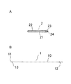
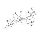
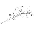
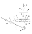
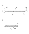
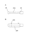
図1は、本実施の形態の構成図で、Aが可撓性圧排部、Bがシャフトを示し、図2は、Aが本形態の可撓性圧排部が湾曲変形された形状例を、Bが前記シャフトの先端部分の拡大図を示している。また、図3は、前記シャフトと可撓性圧排部が接続された状態を示している。
本形態の臓器圧排器具は、腹腔鏡下手術の中でも特に単孔式手術などの小切開創を設けて行われる手術に好適となる器具として提供され、該小切開創と別に設ける極めて小さな切開部からトロッカー52を通して、あるいは、トロッカーを通さず直接経皮的に、腹腔内に導入される圧排部を体外から操作するためのシャフト1と、前記小切開創から前記シャフト1の操作により腹腔内に導入される、圧排のさいの圧排面を形成する可撓性圧排部2より構成し、該シャフト1と可撓性圧排部2の各々に設けた接続手段13、24により着脱自在に形成されてなる。
Hereinafter, a first embodiment of an organ retraction device of the present invention will be described in detail with reference to the drawings.
FIG. 1 is a configuration diagram of the present embodiment, in which A is a flexible displacement portion, B is a shaft, and FIG. 2 is a shape example in which A is a curved deformation of the flexible displacement portion of the present embodiment. B shows an enlarged view of the tip portion of the shaft. FIG. 3 shows a state in which the shaft and the flexible exclusion portion are connected.
The organ retraction device of the present embodiment is provided as a device suitable for a surgery performed by providing a small incision such as a single-hole operation among laparoscopic operations, and an extremely small incision provided separately from the small incision Through the
シャフト1は、ステンレス等の金属棒あるはパイプより形成され、先端11が、腹腔内への挿入あるいは操作時に臓器や腹腔内組織を損傷しないように角部のない丸みを帯びた鈍な形状に形成されるシャフト本体10と、シャフト本体10の基部に接続してシャフトの操作把持部となるホールド部12を備えて構成した。また、シャフト本体10の先端11に隣接して、後記する可撓性圧排部2と接続するための接続手段としてねじ部13を設けて形成される。そして、シャフト本体10は体表から腹腔内に細径のトロッカーを通して、あるいは、使用せずに、直接導入するリデュースポートサージカルに適用する器具となることから、極力小さな切開創から挿入可能な小さな径であることが好ましいが、圧排操作時の強度も考慮して1.5mm以上、3.8mm以下とした。長さは操作性を考慮して300mm以上、450mm以下とすることが好ましい。
The
可撓性圧排部2は、手指あるいは鉗子により形状を自在に湾曲変形可能で、該変形した形状が容易に崩れない保形性を有する可撓性金属21よりなる一連の長尺体として形成し、臓器への圧排(接触)を愛護的なものとするために該金属長尺体21を柔軟な樹脂よりなる保護チューブ22により被覆して構成した。また、前記シャフト10先端部分と接続するための接続手段として、前記金属長尺体21の基部接続基23にねじ部24を設けて形成した。尚、圧排部2は、予め小切開創から挿入可能な特定の大きさ及び形状に形成されているものでも良く、その場合は、必ずしも可撓性を備えている必要はない。
The
本例の可撓性を備えた金属長尺体21としては、アニール処理されたステンレス棒やパイプなどの可撓性金属が使用でき、使用前は棒状体として提供される。また、該金属長尺体21に被覆される保護チューブ22はシリコン樹脂などの柔軟なものが使用され、また、該保護チューブ22の表面には圧排のさいの滑り止めとなる凹凸加工(図示せず)がなされていることが好ましい。サイズは圧排する臓器、あるいは、切開創からの変形された形状での挿入を考慮して外径10mm程度、長さ70mm〜90mm程度に形成することが好ましい。
As the
そして、前記シャフト1及び可撓性圧排部2は、使用前各々分離された状態で提供され、手術の中でシャフト1の先端部分に設ける雄ねじ13と、可撓性圧排部2の接続基23に設ける雌ねじ24が接続され、一体として本形態の臓器圧排器具として使用される。
尚、シャフト1及び可撓性圧排部2に備える接続手段は前記したねじ13、24による接続に限定されるものではなく、圧排操作による容易に離脱することがなく、また、手指操作により着脱容易な手段であればどのような接続手段を用いても良い。
The
Note that the connecting means provided in the
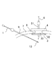
図4〜図8は、本実施の形態の臓器圧排器具を腹腔内へ導入するための手順を模式図で示している。
本臓器圧排器具を腹腔内に導入する前、単孔式手術のため臍部が2cm〜3cm切開され、該切開創の腹壁7に開創を維持するための開創器具3、及び、腹腔内へ内視鏡6や処置具を、トロッカー51を通して気密的に装着するための挿入口を備える挿入ポート4が装着される。
ここで本例に用いる開創器具3及び挿入ポート4を説明する。開創器具3は、腹壁7を挟み体表に位置する上リング31と、腹腔内に位置する下リング32と、上リング31と下リング32に両端部を拡張して接続した体表から腹腔内に腹壁7と接した状態で設ける筒状の弾性シート33から構成され、該弾性シート33が上リング31と下リング32により拡張され生じた張力により開創を維持するものである。
一方、挿入ポート4は、複数のトロッカー51を挿入可能なポート面41と、前記開創器具3の上リング31と係合して着脱される装着部42を備えた、開創器具3に対するキャップのような器具として形成される。ここで、単孔式手術に用いられる開創器具3、及び、挿入ポート4はこれを一体として形成される器具もあるが、本器具が有効に適用となるものは、前記のような各々分離可能な器具である。
4 to 8 schematically show a procedure for introducing the organ retraction device of the present embodiment into the abdominal cavity.
Before introducing the organ retraction device into the abdominal cavity, the umbilical portion is incised 2 to 3 cm for single-hole surgery, and the
Here, the
On the other hand, the
本臓器圧排器具を腹腔内に導入する手順は次の通りとなる。
1.臍部の切開創8に開創器具3と挿入ポート4を装着し、該挿入ポート4からトロッカー51を通して腹腔鏡6を挿入する。そして、該腹腔鏡6の観察下に、前記単孔式手術用の切開創8とは別に設けるごく小さな切開創9に穿設した細径(内径3mm)のトロッカー52を通して本臓器圧排器具のシャフト1を挿入する。(図4)尚、本例では、シャフト1の導入に細径のトロッカー52を使用しているが、強度等に問題が無ければトロッカー52を使用せずに経皮的に直接挿入しても良い。
2.腹腔鏡6の画像を確認しながら、体外操作によりシャフト1の先端11を小切開創8部分(開創器具3の内腔部分)に誘導する。一方、可撓性圧排部2は手指により圧排に適当な大きさ、形状となるように変形する。(図5)
3.開創器具3から挿入ポート4部分を外して、シャフト先端11を体外に位置させ、シャフト1の接続手段となる雄ねじ13と、可撓性圧排部2の接続手段となる雌ねじ24を接続して一体の器具とする。(図6)
4.切開創8(開創器具3の内腔)から、シャフト1に接続された可撓性圧排部2を腹腔内に挿入する。(図7)
5.挿入ポート4を開創器具3に再装着し、腹腔鏡下に目的臓器を圧排する。(図8)
尚、本手順では、可撓性圧排部2は、シャフト1への接続及び腹腔内に挿入するのに先立ち手指により適当な大きさ、形状へと変形されるが、シャフト1に接続し腹腔内に挿入した後、鉗子により適当な大きさ、形状へと変形しても良い。また、腹腔内挿入前に体外でおおよその形状に形成し、腹腔内で鉗子により適当な形状に形成されるものでも良い。
The procedure for introducing the organ retraction device into the abdominal cavity is as follows.
1. The
2. While confirming the image of the
3. The
4). The
5. The
In this procedure, the
このような手順により腹腔内に臓器圧排器具を導入すると、トロッカーを通すのに比較して、大きな導入口が確保できることで、大きな圧排部を適用しての範囲の広い安定した圧排が可能となる。また、シャフト1と圧排部2とを体外で接続するため、手指による直視下での接続操作が可能となる。更に、可撓性圧排部2が手指あるいは鉗子により自在に形状変形することにより症例に適合した圧排面を形成することができる。
By introducing an organ retraction device into the abdominal cavity by such a procedure, a large introduction port can be secured as compared with passing through a trocar, so that a stable retraction with a wide range by applying a large retraction portion becomes possible. . Moreover, since the
本発明の臓器圧排器具の圧排部は、前記第1の実施の形態に限らず、細径(内径5mm以下)のトロッカーから挿入することが難しく、単孔式手術の小切開創から導入できるあらゆる圧排部を適用することができる。以下、その実施例を示すが、これらの例に限定されるものではない。 The retraction part of the organ retraction device of the present invention is not limited to the first embodiment, and it is difficult to insert from a trocar having a small diameter (inner diameter of 5 mm or less), and any retraction part that can be introduced from a small incision in single-hole surgery. An exclusion part can be applied. Examples are shown below, but are not limited to these examples.
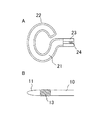
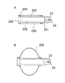
図9は、本発明の第2の実施の形態でバルーンにより形成した圧排部を示し、図10は、Aが該バルーンをシャフトに接続した状態、Bがシャフトの先端部(拡大図)を示している。
本形態のバルーン200は、内部に生理食塩水やエアー等の流体を注入して膨張させ、該膨張部を圧排部とするもので、先端を閉塞端205としバルーン200への流体供給孔203を開けたチューブ201の外層に、バルーン200の両端を接着して被覆し、更に、該接着部を固定チューブ204で固定して形成し、このチューブ201の基端を第1の実施の形態と同様の接続部23に接続したものを圧排部とした。
また、本例においてはバルーン200への流体供給部となる流体注入口121をシャフト1のホールド部120に設け、シャフト本体11はパイプにより形成し内腔を流体通路14とした。尚、流体注入口121の内部には図示しない逆止弁が設けられている。
これにより、流体注入口121から注入される流体は流体通路14、チューブ内腔202、流体供給口203を通ってバルーン200に供給される。
尚、バルーン200への流体の注入は、例えば圧排部の先端に流体注入口を設けて、前記シャフトとの接続前に膨張させる構成としても良いが、本例のように注入口121をホールド部120に設け、腹腔内で膨張させるものとすると、膨張後に小切開創から導入が難しいような大きな圧排部を適用することができる。
FIG. 9 shows an exclusion portion formed by a balloon in the second embodiment of the present invention, FIG. 10 shows a state where A is connected to the shaft, and B shows a tip portion (enlarged view) of the shaft. ing.
The
Further, in this example, a
As a result, the fluid injected from the
The fluid injection into the
圧排部を本例のバルーン200とすると、前記の通り、圧排部の腹腔内への挿入後に膨張させることで小切開から導入できないような大きな圧排部とすることができ、また、注入する流体量により大きさを可変することができる。また、表面が柔軟であることから臓器を愛護的に圧排することができる。
When the exclusion part is the
図11は、本発明の第3の実施の形態で保形性バルーンにより形成された圧排部を示している。
本例の保形性バルーン206は、あらかじめ、厚みを持たせた強度のある弾性ゴムにより内部に空間207を持たせたバルーン状に形成したもので、前記接続基23に基端部を接続することで圧排部を形成する。
本例のバルーン206によると、前記の流体を注入するバルーン200のように膨張により大きさを変えることはできないが、表面が柔軟であることで愛護的な圧排が可能になる。また、成形品として容易に製造することができる。
FIG. 11 shows an exclusion portion formed by a shape-retaining balloon in the third embodiment of the present invention.
The shape-retaining
According to the
図12は、本発明の第4の実施の形態でプレート面により形成された圧排部を示している。
プレート210は樹脂あるいは金属などより形成される圧排面を持った板材で、本例では楕円形状に形成されるが小切開創からの挿入、取り出しに支障のない大きさ及び形状であればどのようなものでも良い。そして、プレート210を前記接続基23と連結部25を介して接続して圧排部とした。尚、連結部25を、くの字に曲げるなどして、プレート210と接続基23(シャフト1)に適当な角度を設けても良い。
圧排部を本例のプレート210とすると、安定した広い圧排面により、特に組織を押圧して保持しておくような圧排の場合に安定した圧排が可能になる。
FIG. 12 shows an exclusion portion formed by a plate surface in the fourth embodiment of the present invention.
The
When the exclusion portion is the
図13は、本発明の第5の実施の形態でプレート面を二又に形成した圧排部を示している。
二又に形成されるプレート211は、前記第4の実施の形態と同様に樹脂あるいは金属により二又形状に形成された圧排面を有する板材で、二又以上の複数に分岐された形状としても良い。第4の実施の形態と同様に連結部25を介して前記接続基23と接続して圧排部を形成する。
本例の複数に分岐したプレート211の圧排部によると、組織を押圧しての圧排の他、プレート211とプレート211の間に組織を挟んでの圧排も可能になる。
FIG. 13 shows an excluding portion in which the plate surface is bifurcated in the fifth embodiment of the present invention.
The
According to the exclusion part of the
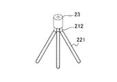
図14は、本発明の第6の実施の形態で3本の棒状体により形成された圧排部を示している。
本形態の圧排部は金属よりなる複数(本例において3本)の棒状体212を適当な角度に放射状に開いて配置し、各々の棒状体212に組織保護のための保護チューブ221を被覆して形成した。そして、3本の圧排棒212を前記接続基23に接続し、3本が同一平面上に配置されるように、くの字に曲げて接続基23(シャフト1)と角度を設けて形成した。
圧排部を本例の複数の棒状体212とすると、前記プレート面と同様に全体として大きな面を安定して圧排することができ、棒状体間に組織を挟んでの圧排も可能になる。また、保護チューブ221により愛護的な圧排ができる。
FIG. 14 shows an exclusion portion formed by three rod-shaped bodies in the sixth embodiment of the present invention.
In this embodiment, a plurality of (three in this example) rod-shaped
When the excluding portions are a plurality of rod-
図15は、本発明の第7の実施の形態で拡開する3枚のプレートにより形成された圧排部を示し、Aが閉塞時の側面断面図、Bが拡開時の上面図を示している。
本形態の圧排部は、圧排面となる複数枚(本例においては3枚)のプレート213とシャフト1に接続すると共にプレート213を可動可能に保持する接続基231より構成し、プレート213は、金属あるいは樹脂よりなる細長形状の板材3枚を重ねて形成される。一方、接続部213はシャフト1との接続部と前記3枚のプレート213を保持するためのスペース233が形成され、該スペース233内に前記プレート213の後端部を3枚重ねた状態で留め置く保持手段232が設けられる。また、重ねられた各々のプレート213の隙間には拡開、閉塞をスムーズにするための緩衝材234が設けられても良い。
そして、前記3枚のプレート213は、手指あるいは鉗子等の器具により保持手段232を支点として回動し、扇子状に拡開することができる。
圧排部を本例の拡開可能な複数のプレート213とすると、該プレート213を拡開することで圧排面の大きさを調整することができ、また、腹腔内挿入時はプレート213を閉じた状態として腹腔内で拡開することにより、拡開した状態で小切開創から挿入することができない様な大きな圧排面を腹腔内で適用することができる。
FIGS. 15A and 15B show an exclusion portion formed by three plates that are expanded in the seventh embodiment of the present invention, where A is a side sectional view when closed and B is a top view when expanded. Yes.
The exclusion part of this embodiment is composed of a plurality of (three in this example)
Then, the three
If the exclusion part is a plurality of
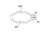
図16は、本発明の第8の実施の形態でループ状に形成される枠体により形成された圧排部を示している。
本形態の圧排部は、超弾性合金などの弾性を有する金属線により両端を前記接続基23に接続した楕円ループ状に形成された枠体214として形成される。
本例の超弾性合金の枠体214による圧排部によると、腹腔内に挿入するさいに押し潰して細径化することで小切開創から大きな圧排部を腹腔内に適用することができ、弾性を利用して枠体214とシャフト1とに角度を設けるなど枠体214を変形させて圧排する余地がある。また、内部空間のある枠体としているため、枠の内側を対象として処置することもできる。
尚、本形態では弾性を備える枠体214としたが弾性のない枠体とすることもでき、その場合小切開創の大きさにより圧排部の大きさは規制されるが、弾性体に比較して安定した押圧による圧排ができる。
また、形状は楕円に限定されるものではなく必要に応じて適当な形状を画定するものであれば良い。
FIG. 16 shows an excluding portion formed by a frame formed in a loop shape in the eighth embodiment of the present invention.
The exclusion part of this embodiment is formed as a
According to the exclusion part by the
In this embodiment, the
Further, the shape is not limited to an ellipse, and may be any shape that defines an appropriate shape as necessary.
図17は、本発明の第9の実施の形態で一部を欠損したループ状の枠体(2本の湾曲した棒状体と見ることもできる)の外層を表面に凹凸加工された保護チューブで被覆した圧排部を示している。
本形態の圧排部は、2本の湾曲した金属棒状体により、前記ループ状に形成する枠体214と同様に端部を接続基23に接続した一部を欠損した楕円ループ状の枠体215として形成し、該枠体215の表面を、適当な凹凸加工223を施した柔軟な樹脂よりなる保護チューブ222で被覆して形成した。
本例の凹凸加工223の施された保護チューブ222を被覆した圧排部によると、組織を愛護的に圧排することができると共に、凹凸加工223が組織接触部との滑り止めとして機能することにより安定した圧排とすることができる。
尚、保護チューブに備える凹凸加工は特定するものではなく、実施の形態のような突起状のものでも、チューブ表面の粗面加工のようなものでも良い。また、当然、該凹凸加工は他の実施の形態の保護チューブなどにも適用することができる。
FIG. 17 shows a protection tube in which an outer layer of a loop-shaped frame body (which can be seen as two curved rod-like bodies) partially lacked in the ninth embodiment of the present invention is processed to have an uneven surface. The covered exclusion part is shown.
The exclusion part of the present embodiment is an
According to the extruding part covering the
In addition, the uneven | corrugated process with which a protection tube is equipped is not specified, A protrusion-like thing like embodiment and the thing of rough surface processing of a tube surface may be sufficient. Needless to say, the uneven processing can be applied to the protective tube of other embodiments.
図18は、本発明の第10の実施の形態で棒状体に綿紗を巻いて形成した圧排部を示している。
本形態の圧排部は、後端部を前記接続基23に接続した金属あるいは樹脂によりなる棒状体の芯材216に綿紗224を適当な厚さになるように複数回巻き付け、該綿紗224が解けないように縫合糸225で結んで形成した。また、本例では芯材216の先端に綿紗224の抜けを防止するストッパー26を備えて構成している。
本例の芯材216に綿紗224を巻いた圧排部とすると、柔軟な接触により組織を愛護的に圧排ができると共に、綿紗224が接触部の滑り止めとして機能することで安定した圧排が可能となる。また、綿紗224による吸水効果により術中に血液などの除去も可能となる。
尚、当然、綿紗224の巻き付けは他の実施の形態にも適用することができる。
FIG. 18 shows an exclusion portion formed by winding a cotton candy around a rod-like body in the tenth embodiment of the present invention.
The exclusion part of this embodiment is obtained by winding a cotton candy 224 a plurality of times around a
When the
Of course, the winding of the
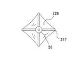
図19は、本発明の第11の実施の形態で4本の棒状体の各々の間にシートを張り渡して形成した圧排部を示している。
本形態の圧排部は、後端部を接続基23に接続し、四方に放射状に配置した4本の棒状体217と、該4本の棒状体217の間を張り渡すシリコン樹脂等による柔軟なシート226とで形成した。
本例のシート226を張り渡した圧排部とすると、柔軟なシートによる圧排となることで組織に愛護的な圧排が可能となり、また、シートを全面に張り渡すことでプレートによる圧排面のように大きな面での圧排が可能となる。
また、本形態の圧排部は、棒状体を傘の親骨としたような傘状に開閉するものとすることもできる。この場合、腹腔内で拡開することで小切開創から挿入できないような大きな圧排面を腹腔内で適用することができる。また、棒状体217を超弾性体で形成しても、挿入時押し潰して細径にすることで同様な効果が期待できる。
尚、当然、シートの張り渡しは他の実施の形態にも適用することができる。
FIG. 19 shows an exclusion portion formed by stretching a sheet between each of the four rod-shaped bodies in the eleventh embodiment of the present invention.
The exclusion part of this embodiment is connected to the
When the
Moreover, the exclusion part of this form can also be opened and closed in the shape of an umbrella such that a rod-like body is the main frame of the umbrella. In this case, a large exclusion surface that cannot be inserted from a small incision by expanding in the abdominal cavity can be applied in the abdominal cavity. Moreover, even if the rod-shaped
Of course, the sheet stretching can also be applied to other embodiments.
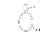
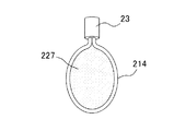
図20は、本発明の第12の実施の形態でループ状に形成する枠体にネットを張り渡して形成した圧排部を示している。
本形態の圧排部は、前記第8の実施の形態のループ状に形成する枠体214の枠体内部にネット227を張り渡して形成した。
本例の枠体214にネット227を張り渡した圧排部とすると、前記シート226を張り渡したものと同様な作用効果が期待できる。
また、枠体214を超弾性体とすると、前記第8の実施の形態で説明した作用効果を期待することができる。
尚、当然、ネットの張り渡しは他の実施の形態にも適用することができる。
FIG. 20 shows an exclusion portion formed by stretching a net over a frame formed in a loop shape in the twelfth embodiment of the present invention.
The exclusion portion of this embodiment is formed by stretching a net 227 inside the frame body of the
When the extruding part with the net 227 stretched over the
Further, when the
Needless to say, the net extension can be applied to other embodiments.
図21は、本発明の第13の実施の形態で球面により形成した圧排部を示している。
本形態の圧排部は、樹脂、あるいは、綿球などよりなる球体218を、連結部25を介して前記接続基23に接続して形成した。
圧排部を球体218とすると角部がないことで組織を創傷する危険性が少ない圧排ができる、また、圧排以外に剥離等の処置にも適用することができる。
また、表面に凹凸加工や粗面加工を施すと滑り防止機能を持たせることができる。
尚、形状は、本例の球面に限定するものではなく、角部が少なく、圧排面が湾曲面より形成されるものであれば良い。
FIG. 21 shows an exclusion portion formed by a spherical surface in the thirteenth embodiment of the present invention.
The exclusion part of this embodiment is formed by connecting a
When the exclusion part is a
In addition, when the surface is subjected to uneven processing or rough surface processing, an anti-slip function can be provided.
The shape is not limited to the spherical surface of the present example, and any shape may be used as long as it has few corners and the exclusion surface is formed of a curved surface.
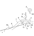
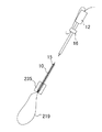
図22は、本発明の第14の実施の形態でループ状に形成されたワイヤーによる圧排部を示し、図23は、それをシャフト1に接続した状態を示している。
本形態の圧排部は、樹脂あるいは金属撚線などよりなるワイヤー219と、シャフト1を接続するねじ24とワイヤー219を通す貫通孔を設けた接続基235により構成し、該接続基235に設ける貫通孔のワイヤー挿入口27は、シャフト本体10の内腔15にスムーズに誘導するためすり鉢状に形成した。そして、該ワイヤー219の両端を接続基235に通してループを形成し構成した。
尚、圧排部をループ状に形成したワイヤーやロープとする場合、シャフト本体11の先端部より直接ワイヤー等の両端部を挿入することも可能であるが、本形態の接続基233には、前記の通りシャフト本体10の内腔と同様な径まですり鉢状に傾斜するワイヤー挿入口27が設けられていることでスムーズにワイヤー219をシャフト内に誘導することができる。
圧排部を本例のループ状のワイヤー219とすると、組織を引っ掛け牽引しての圧排に適用することができる。
FIG. 22 shows an extruding part by a wire formed in a loop shape in the fourteenth embodiment of the present invention, and FIG. 23 shows a state in which it is connected to the
The exclusion part of this embodiment is configured by a
In addition, when the exclusion part is a wire or rope formed in a loop shape, both ends of a wire or the like can be directly inserted from the tip of the
If the excluding portion is the loop-shaped
本形態の圧排器具は、接続基235にシャフト1を接続後、ワイヤー219の両端を、ワイヤー挿入口27から挿入し、シャフト本体10の内腔15を通しホールド部12から突出させ、該ワイヤー219の両端を操作しループを拡縮して組織を保持し、シャフト本体11に設ける糸留め部16にワイヤー両端を留止して形成したループを保持して使用される。
In the exclusion device of this embodiment, after connecting the
以上の実施の形態は例示であって、特許請求の範囲で様々な形状、構成、組合せを採ることができる。 The above embodiments are merely examples, and various shapes, configurations, and combinations can be employed within the scope of the claims.
本発明の基本思想によれば、単孔式手術などの小切開を施しての手術において、本発明の圧排器具に限らず、トロッカー内腔から挿入するには大きさや形状に制約がある処置器具に対しても適用することができる。 According to the basic idea of the present invention, in a surgery with a small incision such as a single-hole surgery, the treatment instrument is not limited to the exclusion device of the present invention, but has a restriction in size and shape for insertion from the trocar lumen. It can also be applied to.
1. シャフト
10. シャフト本体
11. 先端
12. ホールド部
13. 雄ねじ
14. 流体通路
15. 内腔
2. 可撓性圧排部
21. 可撓性金属
22.221.222. 保護チューブ
23.231.235. 接続基
24. 雌ねじ
25. 連結部
200.バルーン
206.保形性バルーン
210.211.213. プレート
212.217. 棒状体
214.215. 枠体
216. 芯材
218. 球体
219. ワイヤー
223. 凹凸加工
224. 綿紗
226. シート
227. ネット
3. 開創器
31. 体表リング
32. 腹腔内リング
33. 弾性シート
4. 挿入ポート
51. トロッカー
52. トロッカー(シャフト挿入用)
6. 腹腔鏡
7. 腹壁
8. (単孔式手術用)切開創
9. (シャフト挿入用)切開創
1.
6).
Claims (21)
Priority Applications (1)
| Application Number | Priority Date | Filing Date | Title |
|---|---|---|---|
| JP2014008237A JP6324082B2 (en) | 2013-01-31 | 2014-01-21 | System device consisting of a retractable device that can be attached / separated with an insertion port and an organ retraction device |
Applications Claiming Priority (3)
| Application Number | Priority Date | Filing Date | Title |
|---|---|---|---|
| JP2013016591 | 2013-01-31 | ||
| JP2013016591 | 2013-01-31 | ||
| JP2014008237A JP6324082B2 (en) | 2013-01-31 | 2014-01-21 | System device consisting of a retractable device that can be attached / separated with an insertion port and an organ retraction device |
Publications (2)
| Publication Number | Publication Date |
|---|---|
| JP2014166345A true JP2014166345A (en) | 2014-09-11 |
| JP6324082B2 JP6324082B2 (en) | 2018-05-16 |
Family
ID=51616407
Family Applications (1)
| Application Number | Title | Priority Date | Filing Date |
|---|---|---|---|
| JP2014008237A Active JP6324082B2 (en) | 2013-01-31 | 2014-01-21 | System device consisting of a retractable device that can be attached / separated with an insertion port and an organ retraction device |
Country Status (1)
| Country | Link |
|---|---|
| JP (1) | JP6324082B2 (en) |
Cited By (1)
| Publication number | Priority date | Publication date | Assignee | Title |
|---|---|---|---|---|
| WO2026005053A1 (en) * | 2024-06-28 | 2026-01-02 | 国立大学法人東北大学 | Medical instrument |
Citations (12)
| Publication number | Priority date | Publication date | Assignee | Title |
|---|---|---|---|---|
| JPH06154152A (en) * | 1992-11-19 | 1994-06-03 | Tomoani Betsupu | Medical retractor |
| JPH1028691A (en) * | 1996-07-18 | 1998-02-03 | Olympus Optical Co Ltd | Pressing extracting piece |
| JP2002113009A (en) * | 2000-08-05 | 2002-04-16 | Heartport Inc | Heart fixing tool, and method of using the same |
| JP2002272677A (en) * | 2001-03-19 | 2002-09-24 | Olympus Optical Co Ltd | Curved retraction tool |
| JP2002360582A (en) * | 2001-06-05 | 2002-12-17 | Hiroyoshi Morita | Internal organ exclusion tool |
| JP2005279010A (en) * | 2004-03-30 | 2005-10-13 | Hakko Co Ltd | Organ exclusion device |
| JP2007307184A (en) * | 2006-05-19 | 2007-11-29 | Tokyo Institute Of Technology | Remote control device used in a closed space |
| US20080242939A1 (en) * | 2007-04-02 | 2008-10-02 | William Johnston | Retractor system for internal in-situ assembly during laparoscopic surgery |
| JP2010194239A (en) * | 2009-02-27 | 2010-09-09 | Kitasato Institute | Variable type levator |
| JP2011083397A (en) * | 2009-10-15 | 2011-04-28 | Osaki Medical Co Ltd | Exclusion implement |
| WO2012094364A2 (en) * | 2011-01-04 | 2012-07-12 | The Johns Hopkins University | Minimally invasive laparoscopic retractor |
| JP2014064609A (en) * | 2012-09-24 | 2014-04-17 | Kagoshima Univ | Percutaneous puncture-type detachable steel wire muscle retractor, and muscle retractor instrument |
-
2014
- 2014-01-21 JP JP2014008237A patent/JP6324082B2/en active Active
Patent Citations (12)
| Publication number | Priority date | Publication date | Assignee | Title |
|---|---|---|---|---|
| JPH06154152A (en) * | 1992-11-19 | 1994-06-03 | Tomoani Betsupu | Medical retractor |
| JPH1028691A (en) * | 1996-07-18 | 1998-02-03 | Olympus Optical Co Ltd | Pressing extracting piece |
| JP2002113009A (en) * | 2000-08-05 | 2002-04-16 | Heartport Inc | Heart fixing tool, and method of using the same |
| JP2002272677A (en) * | 2001-03-19 | 2002-09-24 | Olympus Optical Co Ltd | Curved retraction tool |
| JP2002360582A (en) * | 2001-06-05 | 2002-12-17 | Hiroyoshi Morita | Internal organ exclusion tool |
| JP2005279010A (en) * | 2004-03-30 | 2005-10-13 | Hakko Co Ltd | Organ exclusion device |
| JP2007307184A (en) * | 2006-05-19 | 2007-11-29 | Tokyo Institute Of Technology | Remote control device used in a closed space |
| US20080242939A1 (en) * | 2007-04-02 | 2008-10-02 | William Johnston | Retractor system for internal in-situ assembly during laparoscopic surgery |
| JP2010194239A (en) * | 2009-02-27 | 2010-09-09 | Kitasato Institute | Variable type levator |
| JP2011083397A (en) * | 2009-10-15 | 2011-04-28 | Osaki Medical Co Ltd | Exclusion implement |
| WO2012094364A2 (en) * | 2011-01-04 | 2012-07-12 | The Johns Hopkins University | Minimally invasive laparoscopic retractor |
| JP2014064609A (en) * | 2012-09-24 | 2014-04-17 | Kagoshima Univ | Percutaneous puncture-type detachable steel wire muscle retractor, and muscle retractor instrument |
Cited By (1)
| Publication number | Priority date | Publication date | Assignee | Title |
|---|---|---|---|---|
| WO2026005053A1 (en) * | 2024-06-28 | 2026-01-02 | 国立大学法人東北大学 | Medical instrument |
Also Published As
| Publication number | Publication date |
|---|---|
| JP6324082B2 (en) | 2018-05-16 |
Similar Documents
| Publication | Publication Date | Title |
|---|---|---|
| US5439476A (en) | Inflatable laparoscopic retractor | |
| US10208925B2 (en) | Soft conformal laparoscopic instrument | |
| US8414483B2 (en) | Methods and devices for providing access into a body cavity | |
| US8357088B2 (en) | Methods and devices for providing access into a body cavity | |
| CN101237826B (en) | Surgical retractor | |
| JP5826571B2 (en) | Access device including shape memory deployment mechanism | |
| EP4101405B1 (en) | Natural orifice surgery system | |
| US20170360423A1 (en) | Removable medical retractor tip | |
| CA2494077C (en) | Orifice introducer device | |
| US20130190573A1 (en) | Wound protector including flexible and rigid liners | |
| US20110054258A1 (en) | Foam port introducer | |
| EP2505152B1 (en) | Access port and flexible sleeve with attached cord | |
| CA2700482A1 (en) | Elliptical retractor | |
| JP2013138860A (en) | Wound protector with reinforced ring | |
| AU2011200080A1 (en) | Surgical retrieval apparatus | |
| AU2010201012A1 (en) | Surgical access port and associated introducer mechanism | |
| US20150245828A1 (en) | Tissue retractor | |
| KR101968479B1 (en) | Tissue Retrieval Device | |
| JP5982497B2 (en) | Laparoscopy seal bridge | |
| JP6324082B2 (en) | System device consisting of a retractable device that can be attached / separated with an insertion port and an organ retraction device | |
| JP2007044395A (en) | Wound retractor | |
| US20090131881A1 (en) | Cannula | |
| JP2010172695A (en) | Suture management system for surgical portal apparatus including spring | |
| JP5221447B2 (en) | Exclusion device | |
| CN206675557U (en) | Through skin traction sting device |
Legal Events
| Date | Code | Title | Description |
|---|---|---|---|
| A621 | Written request for application examination |
Free format text: JAPANESE INTERMEDIATE CODE: A621 Effective date: 20170118 |
|
| A977 | Report on retrieval |
Free format text: JAPANESE INTERMEDIATE CODE: A971007 Effective date: 20171012 |
|
| A131 | Notification of reasons for refusal |
Free format text: JAPANESE INTERMEDIATE CODE: A131 Effective date: 20171020 |
|
| A521 | Request for written amendment filed |
Free format text: JAPANESE INTERMEDIATE CODE: A523 Effective date: 20171127 |
|
| A131 | Notification of reasons for refusal |
Free format text: JAPANESE INTERMEDIATE CODE: A131 Effective date: 20180206 |
|
| A521 | Request for written amendment filed |
Free format text: JAPANESE INTERMEDIATE CODE: A523 Effective date: 20180315 |
|
| TRDD | Decision of grant or rejection written | ||
| A01 | Written decision to grant a patent or to grant a registration (utility model) |
Free format text: JAPANESE INTERMEDIATE CODE: A01 Effective date: 20180403 |
|
| A61 | First payment of annual fees (during grant procedure) |
Free format text: JAPANESE INTERMEDIATE CODE: A61 Effective date: 20180410 |
|
| R150 | Certificate of patent or registration of utility model |
Ref document number: 6324082 Country of ref document: JP Free format text: JAPANESE INTERMEDIATE CODE: R150 |