JP2014166328A - Game machine - Google Patents
Game machine Download PDFInfo
- Publication number
- JP2014166328A JP2014166328A JP2013269021A JP2013269021A JP2014166328A JP 2014166328 A JP2014166328 A JP 2014166328A JP 2013269021 A JP2013269021 A JP 2013269021A JP 2013269021 A JP2013269021 A JP 2013269021A JP 2014166328 A JP2014166328 A JP 2014166328A
- Authority
- JP
- Japan
- Prior art keywords
- random number
- game
- value
- state
- special
- Prior art date
- Legal status (The legal status is an assumption and is not a legal conclusion. Google has not performed a legal analysis and makes no representation as to the accuracy of the status listed.)
- Granted
Links
Images


Landscapes
- Pinball Game Machines (AREA)
Abstract
【課題】正確な乱数値を取得する。
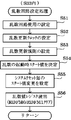
【解決手段】乱数値レジスタに数値データが格納されたときに、対応する乱数ラッチフラグがオン状態に設定され、新たな数値データの格納が制限される。乱数値レジスタから数値データを読み出したときに、対応する乱数ラッチフラグがオフ状態に設定され、新たな数値データの格納が許可される。セキュリティ時間設定KSESの設定により、セキュリティ時間の可変設定を可能にする。大入賞口カウントスイッチによって遊技球が検出されたことに基づき、所定個数(例えば14個)の遊技球が賞球として払い出される。特別可変入賞球装置では、大入賞口扉用ソレノイドがオフ状態であるときに、大入賞口扉が大入賞口を第1の状態としての閉鎖状態にする。他方、大入賞口扉用ソレノイドがオン状態であるときには、大入賞口扉が大入賞口を第2の状態としての開放状態にする。
【選択図】図55An accurate random value is obtained.
When numerical data is stored in a random value register, a corresponding random number latch flag is set to an on state, and storage of new numerical data is restricted. When the numerical data is read from the random value register, the corresponding random number latch flag is set to the off state, and storage of new numerical data is permitted. The security time setting KSES can be set to change the security time. A predetermined number (for example, 14) of game balls are paid out as prize balls based on the detection of the game balls by the big prize opening count switch. In the special variable winning ball apparatus, when the large winning opening door solenoid is in the OFF state, the large winning opening door puts the large winning opening in the closed state as the first state. On the other hand, when the solenoid for the big prize opening door is in the ON state, the big prize opening door puts the big prize opening into the open state as the second state.
[Selection] Figure 55
Description
本発明は、例えばパチンコ遊技機といった、遊技を行うことが可能な遊技機に関する。 The present invention relates to a gaming machine capable of playing a game, such as a pachinko gaming machine.
パチンコ遊技機等の遊技機として、遊技媒体である遊技球を発射装置によって遊技領域に発射し、遊技領域に設けられた入賞口などの入賞領域に遊技球が入賞すると、所定個の遊技球が賞球(景品)として払い出されるものがある。また、始動入賞口に遊技球が入賞したことに基づき可変表示部にて開始される特別図柄などの識別情報の可変表示における表示結果として、予め定められた特定表示結果(大当り)が導出表示された場合に、特定遊技状態としての大当り遊技状態に制御する遊技機がある。大当り遊技状態では、例えば所定の可変入賞装置が所定回数(例えば「15」)に達するまで開放状態となり、遊技球が入賞しやすくなるラウンドが実行される。さらに、識別情報の表示結果として、予め定められた開放表示結果(小当り)が導出表示された場合に、可変入賞装置を遊技球が進入不可能な閉鎖状態から遊技球が進入可能な開放状態とすることがある。 As a gaming machine such as a pachinko gaming machine, a game ball as a game medium is launched into a game area by a launching device, and when a game ball wins in a prize area such as a prize opening provided in the game area, a predetermined number of game balls are Some are paid out as prize balls (prize). In addition, a predetermined specific display result (big hit) is derived and displayed as a display result in the variable display of identification information such as special symbols started by the variable display unit based on the winning of the game ball at the start winning opening. There is a gaming machine that controls to a big hit gaming state as a specific gaming state. In the big hit game state, for example, a predetermined variable winning device is opened until a predetermined number of times (for example, “15”) is reached, and a round in which a game ball is easy to win is executed. Furthermore, when a predetermined open display result (small hit) is derived and displayed as the display result of the identification information, the variable winning device is opened so that the game ball can enter from a closed state where the game ball cannot enter. It may be.
このような遊技機において、始動入賞口に入った入賞球を検出する始動口スイッチがオンすることに対応して、乱数生成手段を構成する乱数確定レジスタに、例えばCPUからのラッチパルスや始動口スイッチからの出力といった、所定信号を入力し、この乱数確定レジスタにラッチされたカウント値を乱数値として取得するものがある(例えば特許文献1)。 In such a gaming machine, in response to the start port switch that detects a winning ball entering the start winning port being turned on, a latch pulse from the CPU or a start port, for example, is added to the random number determination register that constitutes the random number generating means. There is a technique in which a predetermined signal such as an output from a switch is input and a count value latched in the random number determination register is acquired as a random value (for example, Patent Document 1).
特許文献1に記載の技術では、所定信号の入力により乱数確定レジスタにカウント値がラッチされた後、そのカウント値が取得されるより前に、例えばノイズなどにより新たなカウント値がラッチされてしまうと、始動入賞口に入った入賞球などに対応した正確な乱数値を取得できなくなるという問題があった。
In the technique described in
この発明は、上記実状に鑑みてなされたものであり、正確な乱数値を取得できる遊技機を提供することを目的とする。 The present invention has been made in view of the above circumstances, and an object thereof is to provide a gaming machine capable of obtaining an accurate random value.
(1)上記目的を達成するため、本願の請求項に係る遊技機は、遊技を行うことが可能な遊技機(例えばパチンコ遊技機1など)であって、遊技媒体が入賞可能な第1状態(例えば開放状態など)と遊技媒体が入賞不可能な第2状態(例えば閉鎖状態など)とに変化する可変入賞装置(例えば特別可変入賞球装置7など)と、所定期間(例えばステップS1〜S14からなるセキュリティチェック処理の実行期間など)が経過した後、不揮発性メモリ(例えばROM506など)の記憶内容に基づき遊技機における遊技制御を実行する制御用CPU(例えばCPU505など)が内蔵された遊技制御用マイクロコンピュータ(例えば遊技制御用マイクロコンピュータ100など)と、前記遊技制御用マイクロコンピュータに内蔵又は外付けされ、乱数値となる数値データを生成する乱数回路(例えば乱数回路509など)とを備え、前記乱数回路は、数値データを予め定められた手順により更新して出力する数値更新手段(例えば乱数生成回路553や乱数列変更回路555など)と、前記数値更新手段から出力された数値データを前記乱数値として取り込んで格納する乱数値格納手段(例えば乱数値レジスタ559A(R1D)や乱数値レジスタ559B(R2D)など)とを含み、前記遊技制御用マイクロコンピュータは、前記乱数回路によって生成された乱数値を用いて、前記制御用CPUにより所定の決定を行う制御決定手段(例えばCPU505がステップS228、S229、S232の処理を実行する部分など)と、所定信号(例えば第1始動入賞信号SS1や第2始動入賞信号SS2に基づく乱数ラッチ信号LL1、LL2など)の入力に基づいて前記数値更新手段から出力された数値データが前記乱数値格納手段に格納されたときに第1の値にされて新たな数値データの格納を制限する一方、前記乱数値格納手段に格納された数値データが前記乱数値の読出タイミングにて前記制御用CPUにより読み出されたときに第2の値にされて新たな数値データの格納を許可する所定のデータ(例えば乱数ラッチフラグRDFM0、RDFM1など)と、前記所定期間において前記不揮発性メモリの記憶内容が変更されたか否かを検査するセキュリティチェックを実行するセキュリティチェック手段(例えばCPU505がステップS9〜ステップS14の処理を実行する部分など)と、前記所定期間を可変設定可能な開始期間設定手段(例えばセキュリティ時間設定KSESのビット番号[2−0]に基づきCPU505がステップS1〜ステップS4の処理を実行する部分や、セキュリティ時間設定KSESのビット番号[4−3]に基づきCPU505がステップS5〜ステップS8の処理を実行する部分など)と、前記可変入賞装置に遊技媒体が入賞したことに基づいて、所定の遊技価値を付与する価値付与手段(例えばCPU505がステップS145の大当り開放中処理やステップS98の賞球処理を実行する部分など)とを含む。
(1) In order to achieve the above object, the gaming machine according to the claims of the present application is a gaming machine capable of playing a game (for example,
このような構成によれば、正確な乱数値を取得することができる。 According to such a configuration, an accurate random value can be acquired.
(2)あるいは、本願に係る遊技機は、始動領域(例えば普通入賞球装置6Aが形成する第1始動入賞口や普通可変入賞球装置6Bが形成する第2始動入賞口など)を遊技媒体(例えば遊技球など)が通過した後に、可変表示の開始を許容する開始条件の成立(例えばステップS221またはステップS223にてNoと判定されたことなど)に基づいて、各々を識別可能な複数種類の識別情報(例えば特別図柄や飾り図柄など)の可変表示を行い表示結果を導出表示する可変表示手段(例えば第1及び第2特別図柄表示装置4A、4Bや画像表示装置5など)と、遊技媒体が進入可能な開放状態と遊技媒体が進入不可能な閉鎖状態とに変化する開閉動作を行う可変入賞装置(例えば可変入賞装置40など)と、前記可変入賞装置に設けられた複数の領域(例えば特定領域49及び通常領域50など)のうち特定領域(例えば特定領域49など)を通過した遊技媒体を検出する特定検出手段(例えば特定領域スイッチ24など)とを備え、前記可変表示手段に開放表示結果(例えば「小当り」の特図表示結果など)が導出表示されたときに前記可変入賞装置に前記開閉動作を実行させ、前記開閉動作にて前記開放状態となった前記可変入賞装置に進入した遊技媒体が前記特定検出手段により検出されたときと、前記可変表示手段に特定表示結果(例えば「大当り」の特図表示結果など)が導出表示されたときに、遊技者にとって有利な特定遊技状態(例えば大当り遊技状態など)に制御する遊技機(例えばパチンコ遊技機1など)であって、所定の初期設定(例えばステップS1〜S14からなるセキュリティチェック処理など)を実行した後、不揮発性メモリ(例えばROM506など)の記憶内容に基づき遊技機における遊技制御を実行する制御用CPU(例えばCPU505など)が内蔵された遊技制御用マイクロコンピュータ(例えば遊技制御用マイクロコンピュータ100など)と、前記遊技制御用マイクロコンピュータに内蔵又は外付けされ、乱数値となる数値データを生成する乱数回路(例えば乱数回路509など)とを備え、前記乱数回路は、数値データを予め定められた手順により更新して出力する数値更新手段(例えば乱数生成回路553や乱数列変更回路555など)と、前記数値更新手段から出力された数値データを前記乱数値として取り込んで格納する乱数値格納手段(例えば乱数値レジスタ559A(R1D)や乱数値レジスタ559B(R2D)など)とを含み、前記遊技制御用マイクロコンピュータは、前記始動領域を遊技媒体が通過したときに、前記乱数値格納手段から前記乱数値を読み出す乱数読出手段(例えばCPU505がステップS506の処理を実行する部分など)と、前記開始条件が成立したことに基づいて、前記乱数読出手段によって読み出された前記乱数値を用いて、前記可変表示手段に導出表示される表示結果を前記特定表示結果とするか否かの決定と、前記開放表示結果とするか否かの決定とを行う事前決定手段(例えばCPU505がステップS228、S229、S232の処理を実行する部分など)と、所定信号(例えば第1始動入賞信号SS1や第2始動入賞信号SS2に基づく乱数ラッチ信号LL1、LL2など)の入力に基づいて前記数値更新手段から出力された数値データが前記乱数値格納手段に格納されたときに第1の値にされて新たな数値データの格納を制限する一方、前記乱数値格納手段に格納された数値データが前記乱数値の読出タイミングにて前記制御用CPUにより読み出されたときに第2の値にされて新たな数値データの格納を許可する所定のデータ(例えば乱数ラッチフラグRDFM0、RDFM1など)と、前記所定の初期設定において前記不揮発性メモリの記憶内容が変更されたか否かを検査するセキュリティチェックを実行するセキュリティチェック手段(例えばCPU505がステップS9〜ステップS14の処理を実行する部分など)と、前記セキュリティチェック手段によるセキュリティチェックの実行時間を可変設定可能なセキュリティ時間設定手段(例えばセキュリティ時間設定KSESのビット番号[2−0]に基づきCPU505がステップS1〜ステップS4の処理を実行する部分や、セキュリティ時間設定KSESのビット番号[4−3]に基づきCPU505がステップS5〜ステップS8の処理を実行する部分など)とを含んでもよい。
(2) Alternatively, the gaming machine according to the present application may use a start area (for example, a first start winning opening formed by the normal winning ball apparatus 6A or a second starting winning opening formed by the normal variable winning ball apparatus 6B) as a game medium ( For example, a plurality of types that can be identified based on the establishment of a start condition that permits the start of variable display (for example, it is determined No in step S221 or step S223) after a game ball or the like passes. Variable display means (for example, the first and second special
このような構成によれば、所定信号の入力に基づいて数値データが乱数値格納手段に格納されたときに所定のデータが第1の値にされて新たな数値データの格納が制限される一方、乱数値の読出タイミングにて乱数値格納手段から数値データが読み出されたときに所定のデータが第2の値にされて新たな数値データの格納が許可される。これにより、所定信号の入力に基づいて乱数値格納手段に格納された数値データを、正確な乱数値として取得することができる。また、セキュリティチェック処理の実行時間を可変設定できる。これにより、遊技制御の実行開始タイミングを特定することが困難になり、制御コードの解析結果に基づく狙い撃ちや、いわゆる「ぶら下げ基板」を接続することによる不正行為を、確実に防止することができる。さらに、乱数値格納手段から読み出された乱数値を用いて、可変表示手段に導出表示される表示結果を特定表示結果とするか否かの決定と、開放表示結果とするか否かの決定とが行われる。これにより、正確な乱数値を用いて表示結果を決定することができる。 According to such a configuration, when the numerical data is stored in the random value storage means based on the input of the predetermined signal, the predetermined data is set to the first value and storage of new numerical data is restricted. When the numerical data is read from the random value storage means at the read timing of the random value, the predetermined data is changed to the second value and storage of new numerical data is permitted. Thereby, the numerical data stored in the random number storage means based on the input of the predetermined signal can be acquired as an accurate random value. In addition, the execution time of the security check process can be variably set. Thereby, it becomes difficult to specify the execution start timing of the game control, and it is possible to reliably prevent a sniper based on the analysis result of the control code and an illegal act by connecting a so-called “hanging board”. Further, by using the random number value read from the random value storage means, it is determined whether or not the display result derived and displayed on the variable display means is the specific display result, and whether or not the display result is the open display result. And done. Thereby, a display result can be determined using an accurate random number value.
(3)上記(2)の遊技機において、前記数値更新手段は、数値データを更新可能な所定の範囲において、所定の更新初期値から所定の更新最終値まで循環的に数値データを更新し(例えば乱数生成回路553や乱数列変更回路555により図23や図24に示すような乱数列RSNを生成する部分など)、前記遊技制御用マイクロコンピュータは、当該遊技制御用マイクロコンピュータがシステムリセットされるごとに、前記所定の更新初期値を可変設定可能な乱数初期値設定手段(例えばCPU505がステップS55の処理を実行する部分や、スタート値設定回路554など)を含んでもよい。
(3) In the gaming machine of the above (2), the numerical value updating means cyclically updates numerical data from a predetermined update initial value to a predetermined update final value within a predetermined range in which the numerical data can be updated ( For example, a part for generating a random number sequence RSN as shown in FIG. 23 or FIG. 24 by a random
このような構成においては、数値更新手段が循環的に数値データを更新するために設定される所定の更新初期値を、遊技制御用マイクロコンピュータがシステムリセットされるごとに可変設定できる。これにより、システムリセットの発生後に乱数値となる数値データを特定することが困難になり、狙い撃ちなどによる不正行為を、確実に防止することができる。 In such a configuration, the predetermined update initial value set for the numerical value updating means to cyclically update the numerical data can be variably set every time the game control microcomputer is reset. As a result, it becomes difficult to specify numerical data that becomes a random number value after the occurrence of a system reset, and it is possible to reliably prevent fraudulent acts such as aiming.
(4)上記(3)の遊技機において、遊技機への電力供給が開始された後、前記制御用CPUの動作とは別個に初期値決定用データをカウントするカウント手段(例えばフリーランカウンタ554Aなど)を備え、前記乱数初期値設定手段は、前記カウント手段によってカウントされた初期値決定用データを用いて、前記所定の更新初期値を決定してもよい(例えばCPU505によるステップS55の処理に基づき、スタート値設定回路554がスタート値を設定する部分など)。
(4) In the gaming machine of the above (3), after the power supply to the gaming machine is started, counting means (for example, a free-
このような構成においては、制御用CPUの動作とは別個にカウント手段によってカウントされた初期値決定用データを用いて、所定の更新初期値を決定する。これにより、制御用CPUの動作態様から乱数値となる数値データを特定することが困難になり、狙い撃ちなどによる不正行為を、確実に防止することができる。 In such a configuration, the predetermined update initial value is determined using the initial value determination data counted by the counting means separately from the operation of the control CPU. This makes it difficult to specify numerical data that is a random number value from the operation mode of the control CPU, and it is possible to reliably prevent fraudulent acts such as aiming.
(5)上記(2)から(4)のいずれかの遊技機において、前記不揮発性メモリは、前記遊技制御用マイクロコンピュータに内蔵され、前記遊技制御用マイクロコンピュータは、前記制御用CPU以外による前記不揮発性メモリの外部読出を制限する読出制限回路(例えば内部リソースアクセス制御回路501Aなど)を含んでもよい。 (5) In the gaming machine according to any one of (2) to (4), the nonvolatile memory is built in the game control microcomputer, and the game control microcomputer is a device other than the control CPU. A read restriction circuit (for example, an internal resource access control circuit 501A) that restricts external reading of the nonvolatile memory may be included.
このような構成においては、制御用CPU以外による不揮発性メモリの外部読出を制限する読出制限回路が遊技制御用マイクロコンピュータに含まれている。これにより、不揮発性メモリに記憶されている制御プログラムを遊技制御用マイクロコンピュータの外部から読み出して解析などをすることが困難になり、制御プログラムの解析結果に基づく狙い撃ちや、いわゆる「ぶら下げ基板」を接続することによる不正行為を、確実に防止することができる。 In such a configuration, the game control microcomputer includes a read restriction circuit that restricts external reading of the nonvolatile memory other than by the control CPU. This makes it difficult to read out and analyze the control program stored in the non-volatile memory from the outside of the microcomputer for game control, and to aim at the so-called “hanging board” based on the analysis result of the control program. Unauthorized acts caused by connection can be surely prevented.
(6)上記(2)から(5)のいずれかの遊技機において、前記遊技制御用マイクロコンピュータの外部にて乱数用クロック信号を生成して、前記乱数回路に供給する乱数用クロック生成回路(例えば乱数用クロック生成回路112など)と、前記制御用CPUに供給される制御用クロック信号を生成する制御用クロック生成回路(例えば制御用クロック生成回路111やクロック回路502など)とを備え、前記乱数回路は、前記遊技制御用マイクロコンピュータに内蔵され、前記遊技制御用マイクロコンピュータは、前記乱数用クロック生成回路から供給される乱数用クロック信号の入力状態を前記制御用クロック生成回路にて生成された制御用クロック信号と比較することにより、乱数用クロック信号の入力状態に異常が発生したか否かを判定する乱数用クロック異常判定手段(例えば周波数監視回路551、及び、CPU505がステップS62〜S66の処理を実行する部分など)を含んでもよい。
(6) In any one of the above gaming machines (2) to (5), a random number clock generation circuit that generates a random number clock signal outside the gaming control microcomputer and supplies the random number clock signal to the random number circuit ( For example, a random number clock generation circuit 112) and a control clock generation circuit (for example, the control clock generation circuit 111, the
このような構成においては、乱数用クロック生成回路から供給される乱数用クロック信号の入力状態を制御用クロック生成回路にて生成された制御用クロック信号と比較することにより、乱数用クロック信号の入力状態に異常が発生したか否かを判定する。これにより、乱数値となる数値データの更新動作に異常が発生している状態で遊技制御が実行されてしまうことを防止できる。 In such a configuration, the input state of the random number clock signal is compared by comparing the input state of the random number clock signal supplied from the random number clock generation circuit with the control clock signal generated by the control clock generation circuit. It is determined whether or not an abnormality has occurred in the state. Thereby, it is possible to prevent the game control from being executed in a state in which an abnormality has occurred in the operation of updating the numerical data serving as the random value.
(7)上記(2)から(6)のいずれかの遊技機において、前記遊技制御用マイクロコンピュータは、当該遊技制御用マイクロコンピュータのシステムリセットが解除されて前記制御用CPUによる遊技制御の実行が開始されるときに、前記所定のデータを第2の値にするシステムリセット時処理手段(例えばCPU505がステップS56の処理を実行する部分など)を含んでもよい。
(7) In any one of the gaming machines according to (2) to (6), the gaming control microcomputer is configured to release the system reset of the gaming control microcomputer and execute the gaming control by the controlling CPU. A system reset time processing means (for example, a portion where the
このような構成においては、遊技制御用マイクロコンピュータのシステムリセットが解除されて遊技制御の実行が開始されるときに、システムリセット時処理手段が所定のデータを第2の値にする。これにより、例えば電源投入時などの電源電圧が不安定な状態で誤って乱数値格納手段に格納された数値データを乱数値として取得してしまうことを防止できる。 In such a configuration, when the system reset of the game control microcomputer is released and the execution of the game control is started, the system reset time processing means sets the predetermined data to the second value. Thereby, for example, it is possible to prevent the numerical data stored in the random number storage means from being erroneously acquired as a random value in a state where the power supply voltage is unstable when the power is turned on.
(8)上記(2)から(7)のいずれかの遊技機において、遊技機への電力供給に基づいて生成された所定電源電圧を監視し、該所定電源電圧が低下したことに基づいて検出信号(例えば電源断信号など)を出力する電源監視手段(例えば電源監視回路303など)を備え、前記遊技制御用マイクロコンピュータは、前記電源監視手段から前記検出信号が出力された後、前記遊技制御用マイクロコンピュータが動作停止状態となるまで、前記検出信号の入力状態を繰り返し判定する検出判定手段(例えばCPU505がステップS119の処理を実行する部分など)と、前記検出判定手段によって前記検出信号が入力されていない旨の判定がなされたときに、前記制御用CPUにより遊技制御処理プログラムの先頭から遊技制御の実行を開始させる電断復旧時制御手段(例えばCPU505がステップS124の処理を実行した後、遊技制御用タイマ割込み処理から復帰(リターン)する部分など)と、前記検出判定手段によって前記検出信号が入力されていない旨の判定がなされた後、前記電断復旧時制御手段が前記制御用CPUにより前記遊技制御処理プログラムの先頭から遊技制御の実行を開始させるより前に、前記所定のデータを第2の値にする電断復旧時処理手段(例えばCPU505がステップS121、S123の処理を実行する部分など)とを含んでもよい。
(8) In the gaming machine of any one of (2) to (7), the predetermined power supply voltage generated based on the power supply to the gaming machine is monitored and detected based on the decrease of the predetermined power supply voltage. Power supply monitoring means (for example, a power supply monitoring circuit 303) that outputs a signal (for example, a power-off signal) is provided, and the game control microcomputer performs the game control after the detection signal is output from the power supply monitoring means. Detection detection means (for example, a portion where the
このような構成においては、電源監視手段から検出信号が出力された後、遊技制御用マイクロコンピュータが動作停止状態となるまで、検出判定手段により検出信号の入力状態を繰り返し判定する。そして、検出信号が入力されていない旨の判定がなされた後、制御用CPUにより遊技制御処理プログラムの先頭から遊技制御の実行が開始されるより前に、電断復旧時処理手段が所定のデータを第2の値にする。これにより、例えば所定電源電圧の低下時などの電源電圧が不安定な状態で誤って乱数値格納手段に格納された数値データを乱数値として取得してしまうことを防止できる。 In such a configuration, after the detection signal is output from the power supply monitoring unit, the input state of the detection signal is repeatedly determined by the detection determination unit until the game control microcomputer is stopped. Then, after the determination that the detection signal is not input, before the execution of the game control is started from the head of the game control processing program by the control CPU, the power failure recovery processing means performs predetermined data Is the second value. Thereby, it is possible to prevent the numerical data stored in the random number storage means from being erroneously acquired as a random value when the power supply voltage is unstable, for example, when the predetermined power supply voltage is lowered.
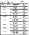
なお、前記事前決定手段による決定前に、前記始動領域を遊技媒体が通過したときに、前記乱数読出手段によって読み出された前記乱数値に基づいて、前記特定遊技状態に制御するか否かを含む所定の判定を行う始動判定手段(例えばCPU505がステップS205、S210にて入賞時乱数値判定処理を実行する部分など)と、前記事前決定手段の決定結果に基づいて、前記識別情報の可変表示パターンを決定する可変表示パターン決定手段(例えばCPU505がステップS251〜S263の処理を実行する部分など)と、前記始動領域を遊技媒体が通過したときに、前記識別情報の可変表示パターンを決定するための可変表示決定用乱数値(例えば変動パターン種別決定用の乱数値MR3など)を抽出する抽出手段(例えばCPU505がステップS508の処理を実行する部分など)と、前記始動領域を遊技媒体が通過したにもかかわらず前記開始条件が成立していない可変表示について、前記乱数読出手段が読み出した前記乱数値と前記抽出手段が抽出した前記可変表示決定用乱数値とを所定の上限数を限度として保留記憶として記憶する保留記憶手段(例えば第1及び第2特図保留記憶部591A、591Bなど)と、前記始動判定手段による判定結果に基づいて、当該判定対象となった可変表示の前記開始条件が成立する以前に、特定演出(例えば図69に示す予告演出YD1や図70に示す予告演出YD2、図71に示す予告演出YD3など)を実行する特定演出実行手段(例えば演出制御用マイクロコンピュータ120のCPUがステップS705〜S709の処理に基づいて、S728〜S731の処理を実行する部分など)とを備え、前記可変表示パターン決定手段は、前記開始条件が成立したときの前記保留記憶手段が記憶する保留記憶数と、前記抽出手段により抽出された前記可変表示決定用乱数値と、複数種類の可変表示パターンに対応した決定値とに基づいて、前記識別情報の可変表示パターンを決定し、前記始動判定手段は、前記抽出手段により抽出された前記可変表示決定用乱数値と、前記複数種類の可変表示パターンに対応した決定値とに基づいて、前記識別情報の可変表示パターンが複数種類の可変表示パターンのうちの特定の可変表示パターン(例えばスーパーリーチを伴う変動パターンなど)となるか否かを判定し(例えばCPU505がステップS527、S532の処理を実行する部分など)、前記特定演出実行手段は、前記始動判定手段によって前記特定遊技状態に制御すると判定された場合または前記特定の可変表示パターンとなると判定された場合に、前記特定演出を実行可能であり(例えば演出制御用マイクロコンピュータ120のCPUがステップS554〜S556、S561〜S563の処理や、ステップS701におけるYesの判定に基づいて、ステップS705〜S709の処理などを実行する部分など)、前記特定の可変表示パターンに対応した決定値のうちの少なくとも一部は、前記開始条件が成立したときの前記保留記憶手段が記憶する保留記憶数にかかわらず、同一決定値(例えば図54に示すような特定パターン共通範囲内となる「230」〜「251」の範囲の値など)が設定され、前記特定の可変表示パターンと異なる非特定の可変表示パターンに対応した決定値は、前記開始条件が成立したときの前記保留記憶手段が記憶する保留記憶数に応じて異なる決定値(例えば図54に示す非リーチやノーマルリーチに割り当てられた決定値など)が設定され、前記始動判定手段は、前記抽出手段により抽出された前記可変表示決定用乱数値が前記同一判定値と合致するか否かを判定することによって、前記特定の可変表示パターンとなるか否かを判定してもよい(例えばCPU505がステップS527、S532にて乱数値MR3が特定パターン共通範囲内であるか否かを判定する部分など)。さらに、前記非特定の可変表示パターンには、リーチ状態が成立しない可変表示パターンであり、前記特定の可変表示パターンと比較して前記識別情報の可変表示を開始してから表示結果を導出表示するまでの可変表示時間が短い短縮用の可変表示パターン(例えば変動パターンPA1−2など)を含み、前記可変表示パターン決定手段は、前記可変表示の開始条件が成立したときの前記保留記憶手段が記憶する保留記憶数が所定数以上である場合(例えば通常時における合計保留記憶数が「3」以上または「6」以上である場合や、時短中における合計保留記憶数が「1」以上または「2」以上である場合など)には、該保留記憶数が所定数未満である場合と比較して、前記短縮用の可変表示パターンに対応した決定値の個数が多く設定された決定値を用いて可変表示パターンを決定してもよい(例えば演出制御用マイクロコンピュータ120のCPUがステップS259、S260にて選択したハズレ変動パターン種別決定テーブル133C、133Dのいずれかを参照してステップS261にて変動パターン種別を決定する部分など)。
Whether or not to control the specific gaming state based on the random number value read by the random number reading means when a game medium passes through the starting area before the determination by the prior determination means. Starting determination means (for example, a portion where the
このような構成においては、特定の可変表示パターンに対応した決定値のうちの少なくとも一部は、開始条件が成立したときの保留記憶数にかかわらず同一決定値が設定され、この同一決定値と可変表示決定用乱数値が合致するか否かを判定することによって、特定の可変表示パターンとなるか否かが判定される。これにより、識別情報の可変表示よりも前に、特定の可変表示パターンとなる旨の判定を確実に行うことができる。また、特定の可変表示パターンと異なる非特定の可変表示パターンに対応した決定値は、開始条件が成立したときの保留記憶数に応じて異なる決定値が設定されるので、保留記憶手段が記憶する保留記憶数に従って可変表示時間を異ならせることができ、可変表示の作動率が低下してしまう事態を極力防止することができる。 In such a configuration, at least a part of the determined values corresponding to the specific variable display pattern is set to the same determined value regardless of the number of reserved memories when the start condition is satisfied. By determining whether or not the random number for determining variable display matches, it is determined whether or not a specific variable display pattern is obtained. This makes it possible to reliably determine that the specific variable display pattern is to be obtained before the variable display of the identification information. In addition, since the determined value corresponding to the non-specific variable display pattern different from the specific variable display pattern is set according to the number of the stored storage when the start condition is satisfied, the determined storage means stores the determined value. The variable display time can be varied according to the number of reserved memories, and the situation where the variable display operating rate is reduced can be prevented as much as possible.
以下、図面を参照しつつ、本発明の一実施形態を詳細に説明する。図1は、本実施の形態におけるパチンコ遊技機の正面図であり、主要部材の配置レイアウトを示す。パチンコ遊技機(遊技機)1は、大別して、遊技盤面を構成する遊技盤(ゲージ盤)2と、遊技盤2を支持固定する遊技機用枠(台枠)3とから構成されている。遊技盤2には、ガイドレールによって囲まれた、ほぼ円形状の遊技領域が形成されている。この遊技領域には、遊技媒体としての遊技球が、図9に示す発射モータ62を含む打球発射装置により発射されて打ち込まれる。
Hereinafter, an embodiment of the present invention will be described in detail with reference to the drawings. FIG. 1 is a front view of a pachinko gaming machine according to the present embodiment and shows an arrangement layout of main members. The pachinko gaming machine (gaming machine) 1 is roughly composed of a gaming board (gauge board) 2 constituting a gaming board surface and a gaming machine frame (base frame) 3 for supporting and fixing the
遊技盤2の所定位置(図1に示す例では、遊技領域の右側方)には、第1特別図柄表示装置4Aと、第2特別図柄表示装置4Bとが設けられている。第1特別図柄表示装置4Aと第2特別図柄表示装置4Bはそれぞれ、例えば7セグメントやドットマトリクスのLED(発光ダイオード)等から構成され、可変表示ゲームの一例となる特図ゲームにおいて、各々が識別可能な複数種類の識別情報(特別識別情報)である特別図柄(「特図」ともいう)を、変動可能に表示(可変表示)する。例えば、第1特別図柄表示装置4Aと第2特別図柄表示装置4Bはそれぞれ、「0」〜「9」を示す数字や「−」を示す記号等から構成される複数種類の特別図柄を可変表示する。なお、第1特別図柄表示装置4Aや第2特別図柄表示装置4Bにて表示される特別図柄は、「0」〜「9」を示す数字や「−」を示す記号等から構成されるものに限定されず、例えば7セグメントのLEDにおいて点灯させるものと消灯させるものとの組合せを異ならせた複数種類の点灯パターンが、複数種類の特別図柄として予め設定されていればよい。複数種類の特別図柄には、それぞれに対応した図柄番号が付されている。一例として、「0」〜「9」を示す数字それぞれには、「0」〜「9」の図柄番号が付され、「−」を示す記号には、「10」の図柄番号が付されていればよい。以下では、第1特別図柄表示装置4Aにより可変表示される特別図柄を「第1特図」ともいい、第2特別図柄表示装置4Bにより可変表示される特別図柄を「第2特図」ともいう。
A first special
第1特別図柄表示装置4Aと第2特別図柄表示装置4Bの上方には、第1保留表示器85Aと、第2保留表示器85Bとが設けられている。第1保留表示器85Aと第2保留表示器85Bはそれぞれ、特図ゲームにおける可変表示の保留記憶数(特図保留記憶数)を特定可能に表示(特図保留記憶表示)する。一例として、第1保留表示器85Aは、第1特別図柄表示装置4Aによる第1特図を用いた特図ゲームにおける可変表示の保留記憶数(第1特図保留記憶数)を特定可能に表示する。第2保留表示器85Bは、第2特別図柄表示装置4Bによる第2特図を用いた特図ゲームにおける可変表示の保留記憶数(第2特図保留記憶数)を特定可能に表示する。特図ゲームにおける可変表示の保留記憶は、普通入賞球装置6Aが形成する第1始動入賞口や普通可変入賞球装置6Bが形成する第2始動入賞口を遊技球が通過(進入)して始動入賞したときに発生する。すなわち、特図ゲームや飾り図柄の可変表示といった可変表示ゲームを実行するための始動条件(「実行条件」ともいう)は成立したが、先に成立した開始条件に基づく可変表示ゲームが実行中であることや、パチンコ遊技機1における遊技状態が大当り遊技状態あるいは小当り遊技状態に制御されていることなどにより、可変表示ゲームを開始するための開始条件が成立していないときに、成立した始動条件に対応する可変表示の保留記憶が行われる。第1保留表示器85Aと第2保留表示器85Bはそれぞれ、例えば第1特図保留記憶数と第2特図保留記憶数のそれぞれにおける上限値(例えば「4」)に対応した個数(例えば4個)のLEDを含んで構成されていればよい。
Above the first special
遊技盤2の所定位置(図1に示す例では、遊技領域の左側方)には、普通図柄表示器20が設けられている。一例として、普通図柄表示器20は、第1特別図柄表示装置4Aや第2特別図柄表示装置4Bと同様に7セグメントやドットマトリクスのLED等から構成され、特別図柄とは異なる複数種類の識別情報である普通図柄(「普図」あるいは「普通図」ともいう)を変動可能に表示(可変表示)する。このような普通図柄の可変表示は、普図ゲーム(「普通図ゲーム」ともいう)と称される。普通図柄表示器20は、例えば「0」〜「9」を示す数字や「−」を示す記号等から構成される複数種類の普通図柄を可変表示する。複数種類の普通図柄には、それぞれに対応した図柄番号が付されている。一例として、「0」〜「9」を示す数字それぞれには、「0」〜「9」の図柄番号が付され、「−」を示す記号には、「10」の図柄番号が付されていればよい。なお、普通図柄表示器20は、「0」〜「9」を示す数字や「−」を示す記号等を普通図柄として可変表示するものに限定されず、例えば「○」と「×」とを示す装飾ランプ(又はLED)を交互に点灯させることや、「左」、「中」、「右」といった複数の装飾ランプ(又はLED)を所定順序で点灯させることにより、普通図柄を可変表示するものであってもよい。
A
普通図柄表示器20の上方には、普図保留表示器85Cが設けられている。普図保留表示器85Cは、普図ゲームにおける可変表示の保留記憶数(普図保留記憶数)を特定可能に表示(普図保留記憶表示)する。ここで、普図ゲームにおける可変表示の保留記憶は、遊技領域に設けられた通過ゲート41を遊技球が通過したときに発生する。すなわち、普図ゲームの可変表示を実行するための条件は成立したが、普図ゲームを開始するための条件が成立していないときに、普図ゲームの保留記憶が行われる。普図保留表示器85Cは、例えば普図保留記憶数の上限値(例えば「4」)に対応した個数(例えば4個)のLEDを含んで構成されていればよい。
Above the
遊技盤2における遊技領域のほぼ中央位置には、可変入賞装置40が設けられている。可変入賞装置40の入賞空間内において、例えば可変入賞装置40の中央背面(奥面)部分などには、画像表示装置5が配置されている。画像表示装置5は、例えば液晶表示装置(LCD:Liquid Crystal Display)等から構成され、各種の演出画像を表示する表示領域を形成している。画像表示装置5の表示領域では、特図ゲームにおける第1特別図柄表示装置4Aによる第1特図の可変表示や第2特別図柄表示装置4Bによる第2特図の可変表示のそれぞれに対応して、例えば3つといった複数に分割された可変表示部となる飾り図柄表示部にて、各々が識別可能な複数種類の識別情報(装飾識別情報)である飾り図柄を可変表示する。
A
一例として、画像表示装置5の表示領域には、「左」、「中」、「右」の飾り図柄表示部5L、5C、5Rが配置されている。そして、特図ゲームにおいて、第1特別図柄表示装置4Aによる第1特図の可変表示と、第2特別図柄表示装置4Bによる第2特図の可変表示とのうち、いずれかの可変表示が開始されることに対応して、「左」、「中」、「右」の飾り図柄表示部5L、5C、5Rの全部において飾り図柄の可変表示(例えば上下方向あるいは左右方向のスクロール表示など)が開始される。その後、特図ゲームにおける可変表示結果として確定特別図柄が停止表示(完全停止表示)されるときに、画像表示装置5における「左」、「中」、「右」の各飾り図柄表示部5L、5C、5Rにて、飾り図柄の可変表示結果となる確定飾り図柄(最終停止図柄)が停止表示(完全停止表示)される。なお、「左」、「中」、「右」の各飾り図柄表示部5L、5C、5Rは、画像表示装置5の表示領域内で移動可能とされ、飾り図柄を縮小あるいは拡大して表示することができるようにしてもよい。特別図柄や飾り図柄が完全停止表示されたときには、各図柄の可変表示における表示結果が確定的に表示され、それ以後は今回の可変表示が進行しないことを遊技者が認識できる表示状態となる。これに対して、飾り図柄の可変表示を開始してから可変表示結果となる確定飾り図柄が完全停止表示されるまでの可変表示中には、飾り図柄の変動速度が「0」となって、飾り図柄が停留して表示され、例えば微少な揺れや伸縮などを生じさせる表示状態となることがある。このような表示状態は、仮停止表示ともいい、可変表示における表示結果が確定的に表示されていないものの、スクロール表示や更新表示による飾り図柄の変動が進行していないことを遊技者が認識可能となる。なお、仮停止表示には、微少な揺れや伸縮なども生じさせず、所定時間(例えば1秒間)よりも短い時間だけ、飾り図柄を完全停止表示することなどが含まれてもよい。完全停止表示や仮停止表示のように、特別図柄や飾り図柄の変動が進行していないことを遊技者が認識できる程度に表示図柄を停止表示することは、導出表示ともいう。
As an example, “left”, “middle”, and “right” decorative
「左」、「中」、「右」の各飾り図柄表示部5L、5C、5Rにて可変表示される飾り図柄には、例えば8種類の図柄(英数字「1」〜「8」あるいは漢数字「一」〜「八」、英文字「A」〜「H」、所定のモチーフに関連する8個のキャラクタを示す演出画像、数字や文字あるいは記号とキャラクタとを組み合わせた演出画像など。なお、キャラクタを示す演出画像は、例えば人物や動物、これら以外の物体、もしくは、文字などの記号、あるいは、その他の任意の図形を示す画像であればよい。)が含まれていればよい。また、こうした8種類の飾り図柄の他に、ブランク図柄(大当り組合せを構成しない図柄)が含まれていてもよい。飾り図柄のそれぞれには、対応する図柄番号が付されている。例えば、「1」〜「8」を示す英数字それぞれに対して、「1」〜「8」の図柄番号が付されている。なお、可変表示される飾り図柄の種類数は、8種類のものに限定されず、任意の複数種類からなる飾り図柄であればよい。
The decorative symbols variably displayed on the “left”, “middle”, and “right” decorative
飾り図柄の変動中には、「左」、「中」、「右」の各飾り図柄表示部5L、5C、5Rにおいて、例えば図柄番号が小さいものから大きいものへと順次に、上方から下方へ、あるいは、右側から左側へと、流れるようなスクロール表示が行われる。そして、図柄番号が最大(例えば「8」)である飾り図柄が表示されると、続いて図柄番号が最小(例えば「1」)である飾り図柄が表示される。あるいは、飾り図柄表示部5L、5C、5Rのうち少なくともいずれか1つ(例えば「左」の飾り図柄表示部5Lなど)において、図柄番号が大きいものから小さいものへとスクロール表示を行って、図柄番号が最小である飾り図柄が表示されると、続いて図柄番号が最大である飾り図柄が表示されるようにしてもよい。
While the decorative symbols are changing, in the decorative
また、画像表示装置5の表示領域には、普通入賞球装置6Aに進入した有効進入球数としての第1特図保留記憶数や普通可変入賞球装置6Bに進入した有効進入球数としての第2特図保留記憶数を表示する特別図柄始動記憶表示エリアが設けられていてもよい。具体的な一例として、第1特図保留記憶数が1加算されたときには、通常非表示であった表示部位のうちの1つ(例えば非表示となっている表示部位のうち左端の表示部位)を赤色表示に変化させる。また、第2特図保留記憶数が1加算されたときには、通常非表示であった表示部位のうちの1つ(例えば非表示となっている表示部位のうち左端の表示部位)を黄色表示に変化させる。これに対して、第1特図保留記憶数が1減算されたときには、赤色表示されている表示部位のうちの1つ(例えば赤色となっている表示部位のうち右端の表示部位)を非表示に戻す。また、第2特図保留記憶数が1減算されたときには、黄色表示されている表示部位のうちの1つ(例えば黄色となっている表示部位のうち右端の表示部位)を非表示に戻す。あるいは、特別図柄始動記憶表示エリアでは、第1特図保留記憶数や第2特図保留記憶数を示す数字を表示することなどにより、第1特図保留記憶数や第2特図保留記憶数を遊技者等が認識できるようにしてもよい。あるいは、特別図柄始動記憶表示エリアでは、第1特図保留記憶数と第2特図保留記憶数とを区別することなく、例えば各保留記憶数の加算値に対応する表示が行われるようにしてもよい。
Further, in the display area of the
こうして、第1始動条件や第2始動条件が成立したものの、先に開始された特図ゲームが実行中であることや、パチンコ遊技機1が大当り遊技状態や小当り遊技状態に制御されていることなどにより、特図ゲームを開始するための開始条件が成立しないときには、特図ゲームに対応した可変表示の保留が発生する。例えば、第1始動条件が成立したときに、当該第1始動条件の成立に基づく第1特図を用いた特図ゲームを開始するための第1開始条件が成立しなければ、第1特図保留記憶数が1加算(インクリメント)され、第1特図を用いた特図ゲームの実行が保留される。また、第2始動条件が成立したときに、当該第2始動条件の成立に基づく第2特図を用いた特図ゲームを開始するための第2開始条件が成立しなければ、第2特図保留記憶数が1加算(インクリメント)され、第2特図を用いた特図ゲームの実行が保留される。これに対して、第1特図を用いた特図ゲームの実行が開始されるときには、第1特図保留記憶数が1減算(デクリメント)され、第2特図を用いた特図ゲームの実行が開始されるときには、第2特図保留記憶数が1減算(デクリメント)される。
Thus, although the first start condition and the second start condition are satisfied, the special game started first is being executed, and the
第1特図保留記憶数と第2特図保留記憶数とを加算した可変表示の保留記憶数は、特に、合計保留記憶数ともいう。単に「特図保留記憶数」というときには、通常、第1特図保留記憶数、第2特図保留記憶数及び合計保留記憶数のいずれも含む概念を指すが、特に、これらの一部(例えば第1特図保留記憶数と第2特図保留記憶数を含む一方で合計保留記憶数は除く概念)を指すこともあるものとする。 The variable display hold memory number obtained by adding the first special figure hold memory number and the second special figure hold memory number is also referred to as a total hold memory number. When simply referring to the “number of special figure hold memory”, it usually refers to a concept including any of the first special figure hold memory number, the second special figure hold memory number, and the total hold memory number. It may refer to a concept that includes the first special figure reserved memory number and the second special figure reserved memory number but excludes the total reserved memory number).
加えて、画像表示装置5の表示領域には、第1特別図柄表示装置4Aや第2特別図柄表示装置4Bにより実行される特図ゲームにて可変表示される特別図柄を、飾り図柄とは別個に特定可能として表示する特別図柄可変表示エリアが設けられていてもよい。一例として、第1特別図柄表示装置4Aや第2特別図柄表示装置4Bによる特図ゲームにて特別図柄の可変表示が開始されたことに対応して、特別図柄可変表示エリアにて特別図柄の可変表示に対応した「◎」や「○」、「×」などを示す演出画像の変動が開始される。その後、特図ゲームにおける特別図柄の可変表示が終了して確定特別図柄が停止表示されることに対応して、特別図柄可変表示エリアにて確定特別図柄に対応して予め定められた「◎」や「○」、「×」などの演出画像を停止表示すればよい。例えば、特図ゲームにおける確定特別図柄が大当り図柄である場合には特別図柄可変表示エリアに「◎」を停止表示し、小当り図柄である場合には「○」を停止表示し、ハズレ図柄である場合には「×」を停止表示すればよい。
In addition, in the display area of the
可変入賞装置40の下方には、普通入賞球装置6A、普通可変入賞球装置6B、特別可変入賞球装置7、一般入賞口42F、42L、42R、アウト口69などが設けられている。普通入賞球装置6Aは、例えば所定の玉受部材によって常に一定の開放状態に保たれる第1始動入賞口を形成する。普通可変入賞球装置6Bは、例えば図9に示す普通電動役物用ソレノイド55によって垂直位置となる通常開放状態と傾動位置となる拡大開放状態とに変化する一対の可動翼片を有する電動チューリップ型役物(普通電動役物)を備え、第2始動入賞口を形成する。一例として、普通可変入賞球装置6Bでは、普通電動役物用のソレノイド81がオフ状態であるときに可動翼片が垂直位置となることにより、遊技球が第2始動入賞口に進入(通過)しにくい通常開放状態となる。その一方で、普通可変入賞球装置6Bでは、普通電動役物用ソレノイド55がオン状態であるときに可動翼片が傾動位置となることにより、遊技球が第2始動入賞口に進入(通過)しやすい拡大開放状態となる。なお、普通可変入賞球装置6Bは、通常開放状態であるときでも、第2始動入賞口には遊技球が進入(通過)可能であるものの、拡大開放状態であるときよりも遊技球が進入(通過)する可能性が低くなるように構成してもよい。あるいは、普通可変入賞球装置6Bは、通常開放状態において、例えば第2始動入賞口を閉鎖することなどにより、第2始動入賞口には遊技球が進入(通過)しないように構成してもよい。
Below the variable winning
特別可変入賞球装置7は、例えば図9に示す大入賞口用ソレノイド54によって開閉駆動される大入賞口扉61を有し、その大入賞口扉61によって、大入賞口60を第1の状態となる開放状態と第2の状態となる閉鎖状態とに変化させる。一例として、特別可変入賞球装置7では、大入賞口扉用ソレノイド54がオフ状態であるときに大入賞口扉61が大入賞口60を閉鎖状態にする。その一方で、特別可変入賞球装置7では、大入賞口扉用ソレノイド54がオン状態であるときに大入賞口扉61が大入賞口60を開放状態にする。
The special variable winning
一般入賞口42F、42L、42Rはそれぞれ、例えば所定の玉受部材によって常に一定の開放状態に保たれる。アウト口69は、遊技領域の最下方において、いずれの入賞領域にも入賞しなかった遊技球を取り込んで遊技領域の外部へと排出する。
Each of the general winning
普通入賞球装置6Aに形成された第1始動入賞口に進入した遊技球は、例えば図9に示す始動口スイッチ22A、22Bのうち、第1始動口スイッチ22Aによって検出される。第1始動口スイッチ22Aによって遊技球が検出されたことに基づき、所定個数(例えば3個)の遊技球が賞球として払い出されるとともに、第1特別図柄表示装置4Aによる特別図柄の可変表示を実行するための第1始動条件が成立して、第1特図保留記憶数が1加算される。ここで、第1特図保留記憶数は、第1始動条件が成立したものの未だ開始されずに保留されている第1特図を用いた特図ゲームの記憶数であり、所定の上限記憶数(例えば「4」)に達するまで特図ゲームを実行可能に保留記憶することができる。したがって、第1特図保留記憶数が上限記憶数に達しているときには、第1始動条件の成立は無効となる。
The game ball that has entered the first start winning opening formed in the normal winning ball apparatus 6A is detected by, for example, the first
普通可変入賞球装置6Bに形成された第2始動入賞口に進入した遊技球は、例えば図9に示す始動口スイッチ22A、22Bのうち、第2始動口スイッチ22Bによって検出される。第2始動口スイッチ22Bによって遊技球が検出されたことに基づき、所定個数(例えば3個)の遊技球が賞球として払い出されるとともに、第2特別図柄表示装置4Bによる特別図柄の可変表示を実行するための第2始動条件が成立して、第2特図保留記憶数が1加算される。ここで、第2特図保留記憶数は、第2始動条件が成立したものの未だ開始されずに保留されている第2特図を用いた特図ゲームの記憶数であり、所定の上限記憶数(例えば「4」)に達するまで特図ゲームを実行可能に保留記憶することができる。従って、第2特図保留記憶数が上限記憶数に達しているときには、第2始動条件の成立が無効となる。
The game ball that has entered the second start winning opening formed in the normal variable winning ball apparatus 6B is detected by, for example, the second start opening switch 22B among the
特別可変入賞球装置7に形成された大入賞口60に進入した遊技球は、例えば図9に示す大入賞口カウントスイッチ28によって検出される。大入賞口カウントスイッチ28によって遊技球が検出されたことに基づき、所定個数(例えば14個)の遊技球が賞球として払い出される。特別可変入賞球装置7では、大入賞口扉用ソレノイド54がオフ状態であるときに、大入賞口扉61が大入賞口60を第1の状態としての閉鎖状態にする。他方、大入賞口扉用ソレノイド54がオン状態であるときには、大入賞口扉61が大入賞口60を第2の状態としての開放状態にする。このように、特別可変入賞球装置7は、遊技者にとって有利な第1の状態と遊技者にとって不利な第2の状態とに変化する特定動作を行う変動入賞装置を構成する。
A game ball that has entered the special winning
一般入賞口42Fに進入した遊技球は、例えば図9に示す一般入賞球スイッチ27F、27L、27Rのうち、第1一般入賞球スイッチ27Fによって検出される。一般入賞口42Lに進入した遊技球は、例えば図9に示す一般入賞球スイッチ27F、27L、27Rのうち、第2一般入賞球スイッチ27Lによって検出される。一般入賞口42Rに進入した遊技球は、例えば図9に示す一般入賞球スイッチ27F、27L、27Rのうち、第3一般入賞球スイッチ27Rによって検出される。一般入賞球スイッチ27F、27L、27Rのいずれかによって遊技球が検出されたことに基づき、所定個数(例えば10個)の遊技球が賞球として払い出される。
The game balls that have entered the general winning
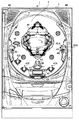
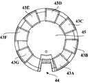
図2(A)及び(B)は、可変入賞装置40の一構成例を拡大して示す図である。可変入賞装置40には、一対の開閉部材となる可動部材として、「左」及び「右」の羽根部材32L、32Rが、摺動変化可能に設けられている。「左」の羽根部材32Lは、例えば連係アームといった所定のリンク機構などを介して、図9に示す開放ソレノイド53におけるコイルに内装されたプランジャなどに連結されている。「右」の羽根部材32Rも、所定のリンク機構などを介して、図9に示す開放ソレノイド53におけるコイルに内装されたプランジャなどに連結されていればよい。あるいは、「左」の羽根部材32Lと「右」の羽根部材32Rのそれぞれに対応して、別個のソレノイドを用意してもよい。
FIGS. 2A and 2B are enlarged views of a configuration example of the variable winning
この実施の形態では、開放ソレノイド53がオン状態であるときに、「左」及び「右」の羽根部材32L、32Rが、「左」及び「右」の役物進入口31L、31Rを、第1の状態としての開放状態にする。他方、開放ソレノイド53がオフ状態であるときには、「左」及び「右」の羽根部材32L、32Rが、「左」及び「右」の役物進入口31L、31Rを、第2の状態としての閉鎖状態にする。なお、「左」及び「右」の羽根部材32L、32Rは、摺動変化可能に構成されたものに限定されず、例えば回動可能に構成されることにより、「左」及び「右」の役物進入口31L、31Rを、第1の状態である開放状態と第2の状態である開放状態とに変化させることができるものであればよい。このように、可変入賞装置40は、遊技者にとって有利な第1の状態と遊技者にとって不利な第2の状態とに変化する始動動作あるいは役物開閉動作(単に「開閉動作」ともいう)を実行することができるように構成されている。このように、「左」及び「右」の羽根部材32L、32Rが「左」及び「右」の役物進入口31L、31Rを開放状態とすることにより、可変入賞装置40は開放状態となり、「左」及び「右」の羽根部材32L、32Rが「左」及び「右」の役物進入口31L、31Rを閉鎖状態とすることにより、可変入賞装置40は閉鎖状態となる。
In this embodiment, when the open solenoid 53 is in the ON state, the “left” and “right”
可変入賞装置40の内部には、例えば「左」及び「右」の上部球経路34L、34Rや、特別球経路37、山ステージ38などといった、遊技球が流下や転動をして通過可能な複数の球経路が設けられている。また、可変入賞装置40の左側には、「左」の足模型51Lを備えた「左」の人形模型47Lが設けられており、可変入賞装置40の右側には、「右」の足模型51Rを備えた「右」の人形模型47Rが設けられている。可変入賞装置40の内部に進入した遊技球は、いずれかの球経路を通過した後に、例えば特定領域49や通常領域50などといった、複数の領域のいずれかに進入して、可変入賞装置40の外部へと排出される。このとき、特定領域49に進入した遊技球は、特定領域スイッチ24によって検出される。すなわち、特定領域スイッチ24は、可変入賞装置40に設けられた複数の領域のうち、特定領域49に進入した遊技球を検出する。この実施の形態では、小当り遊技状態における始動動作で「左」及び「右」の羽根部材32L、32Rにより開放状態となった「左」及び「右」の役物進入口31L、31Rのいずれかより可変入賞装置40の内部に進入した遊技球が、特定領域49に進入して特定領域スイッチ24によって検出されたことに対応して、特定遊技状態としての大当り遊技状態に制御される。
Inside the variable winning
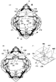
図2(A)では、「左」及び「右」の役物進入口31L、31Rが閉鎖状態となっており、図2(B)では、「左」及び「右」の役物進入口31L、31Rが開放状態となっている。「左」及び「右」の役物進入口31L、31Rはそれぞれ、可変入賞装置40の内部と外部とを連通させる開口部であり、図2(B)に示すような開放状態であるときに、遊技球を可変入賞装置40の外部から内部に進入させることができる。「左」及び「右」の役物進入口31L、31Rのいずれかから可変入賞装置40の内部に進入した遊技球は、図2(B)に示す上部ステージ33上へと誘導される。
In FIG. 2A, the “left” and “right” accessory entrances 31L and 31R are closed, and in FIG. 2B, the “left” and “right” accessory entrances 31L. , 31R is open. The “left” and “right” accessory entrances 31L and 31R are openings that allow the inside and the outside of the variable winning
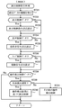
図2(C)は、上部ステージ33の一構成例を拡大して示す図である。図2(C)に示すように、上部ステージ33には、「左」、「中」、「右」の振分穴46L、46C、46Rが形成されている。そして、上部ステージ33では、中央部33Cが左側部33Lや右側部33Rに比べて一段高く盛り上がるように形成されている。そのため、上部ステージ33に誘導された遊技球は、「中」の振分穴46Cに振り分けられて進入する可能性よりも、「左」の振分穴46Lや「右」の振分穴46Rに振り分けられて進入する可能性の方が高くなっている。すなわち、「中」の振分穴46Cは、「左」の振分穴46Lや「右」の振分穴46Rに比べて、遊技球が進入しにくくなるように構成されている。
FIG. 2C is an enlarged view showing a configuration example of the
「左」の振分穴46Lに進入した遊技球は、図9に示す役物カウントスイッチ23L、23C、23Rのうち、図2(B)に示す「左」の役物カウントスイッチ23Lによって検出される。「中」の振分穴46Lに進入した遊技球は、役物カウントスイッチ23L、23C、23Rのうち、図2(B)に示す「中」の役物カウントスイッチ23Cによって検出される。「右」の振分穴46Rに進入した遊技球は、役物カウントスイッチ23L、23C、23Rのうち、図2(B)に示す「右」の役物カウントスイッチ23Rによって検出される。このようにして、役物カウントスイッチ23L、23C、23Rはそれぞれ、可変入賞装置40に進入した遊技球を検出する。役物カウントスイッチ23L、23C、23Rのいずれかによって遊技球が検出されたことに基づき、所定個数(例えば10個)の遊技球が賞球として払い出される。「左」の振分穴46Lに進入した遊技球と、「右」の振分穴46Rに進入した遊技球は、図2(A)に示す「左」の上部球経路34Lへと誘導される。「中」の振分穴46Cに進入した遊技球は、図2(A)に示す「右」の上部球経路34Rへと誘導される。
The game ball that has entered the “left”
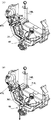
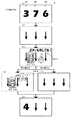
図3(A)及び(B)は、「左」の上部球経路34Lへと誘導された遊技球の流れを示す図である。図2(A)や図3(A)及び(B)に示すように、「左」の上部球経路34Lの付近には、装飾模型の一例として、「左」の人形模型47Lが設けられている。「左」の人形模型47Lには、振分部材となる可動部材の一例として、「左」の足模型51Lが取り付けられている。「左」の足模型51Lは、所定のリンク機構などを介して、図9に示す模型用ソレノイド52L、52Rのうち、「左」の模型用ソレノイド52Lにおけるコイルに内装されたプランジャなどに連結されている。なお、「左」の模型用ソレノイド52Lは、「左」の人形模型47Lに取り付けられた「左」の口飾り模型などにも連結され、「左」の足模型51Lと連係して動作させるようにしてもよい。
FIGS. 3A and 3B are diagrams showing the flow of the game ball guided to the “left”
「左」の模型用ソレノイド52Lがオン状態であるときには、図3(A)に示すように、「左」の足模型51Lが「左」の上部球経路34Lを流下する遊技球には接触しないよう遊技球の経路よりも上方向に保持される。このとき、「左」の上部球経路34Lを流下した遊技球は、「左」の足模型51Lには接触することなく、下部ステージ35へと振り分けられるように誘導される。「左」の模型用ソレノイド52Lがオフ状態であるときには、図3(B)に示すように、「左」の足模型51Lが下方向に移動して、「左」の上部球経路34Lを流下する遊技球と接触する。このとき、「左」の上部球経路34Lを流下した遊技球は、「左」の足模型51Lに接触して、「左」の下部球経路36Lへと振り分けられるように誘導される。
When the “left” model solenoid 52L is in the ON state, the “left” foot model 51L does not contact the game ball flowing down the “left”
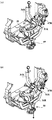
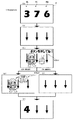
図4(A)及び(B)は、「右」の上部球経路34Rへと誘導された遊技球の流れを示す図である。図2(A)や図4(A)及び(B)に示すように、「右」の上部球経路34Rの付近には、装飾模型の一例として、「右」の人形模型47Rが設けられている。「右」の人形模型47Rには、振分部材となる可動部材の一例として、「右」の足模型51Rが取り付けられている。「右」の足模型51Rは、所定のリンク機構などを介して、図9に示す模型用ソレノイド52L、52Rのうち、「右」の模型用ソレノイド52Rにおけるコイルに内装されたプランジャなどに連結されている。なお、「右」の模型用ソレノイド52Rは、「右」の人形模型47Rに取り付けられた「右」の口飾り模型などにも連結され、「右」の足模型51Rと連係して動作させるようにしてもよい。
4A and 4B are diagrams showing the flow of the game ball guided to the “right”
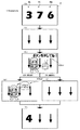
「右」の模型用ソレノイド52Rがオン状態であるときには、図4(A)に示すように、「右」の足模型51Rが「右」の上部球経路34Rを流下する遊技球には接触しないよう遊技球の経路よりも上方向に保持される。このとき、「右」の上部球経路34Rを流下した遊技球は、「右」の足模型51Rには接触することなく、特別球経路37へと振り分けられるように誘導される。特別球経路38を通過する遊技球は、山ステージ38へと誘導される。「右」の模型用ソレノイド52Rがオフ状態であるときには、図4(B)に示すように、「右」の足模型51Rが下方向に移動して、「右」の上部球経路34Rを流下する遊技球と接触する。このとき、「右」の上部球経路34Rを流下した遊技球は、「右」の足模型51Rに接触して、「右」の下部球経路36Rへと振り分けられるように誘導される。
When the “right” model solenoid 52R is in the ON state, as shown in FIG. 4A, the “right” foot model 51R does not contact the game ball flowing down the “right”
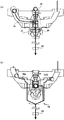
山ステージ38の直下方には、振分部材となる可動部材の一例として、図5に示すような回転体45が、図9に示すモータ56の回転軸に取り付けられることにより回転可能に設けられている。回転体45は、パチンコ遊技機1に電源が投入されている間、モータ56の駆動力により一定の速度で常時回転動作(回動)を行うようにしてもよい。あるいは、可変入賞装置40において「左」及び「右」の羽根部材32L、32Rが「左」及び「右」の役物進入口31L、32Rを閉鎖状態から開放状態とすることに対応した所定期間において、モータ56の駆動力により所定の回動態様で回転動作を行い、所定期間が終了するときには、回転動作を停止するようにしてもよい。
As an example of a movable member serving as a distribution member, a rotating
図5に示すように、回転体45には、それぞれ遊技球を進入させて保持可能な複数の進入穴が形成されている。図5に示す例では、回転体45に、7つのハズレ穴43A〜43Gと、1つのV穴44とが形成されている。各ハズレ穴43A〜43Gは、回転体45の外周側が閉鎖されたロ字状に形成され、各ハズレ穴43A〜43Gに進入した遊技球を通常領域50へと誘導する。V穴44は、回転体45の外周側が開放されたコ字状に形成され、V穴44に進入した遊技球を特定領域49へと誘導することができる。
As shown in FIG. 5, the rotating
図6(A)は、山ステージ38から放出された遊技球や下部ステージ35を通過した遊技球が、回転体45のV穴44に進入した後、V穴44から放出されて特定領域49に進入するように誘導される様子を示している。また、山ステージ38から放出された遊技球は、回転体45の上面をハズレ穴43A〜43GやV穴44に進入することなく通過した後、特定領域49に直接進入するように誘導されることがある。これにより、山ステージ38を通過した遊技球は、下部ステージ35を通過した遊技球に比べて、特定領域49に進入しやすくなる。そして、山ステージ38に誘導される遊技球は「右」の上部球経路34Rを通過した遊技球であるのに対して、下部ステージ35に誘導される遊技球は「左」の上部球経路34Lを通過した遊技球であることから、「右」の上部球経路34Rへと誘導された遊技球の方が、「左」の上部球経路34Lへと誘導された遊技球に比べて、特定領域49に進入しやすくなる。したがって、「右」の上部球経路34Rの方が、「左」の上部球経路34Lに比べて、遊技者にとって有利な経路となるように構成されている。図6(A)に示すように、特定領域49に進入した遊技球は、特定領域スイッチ24によって検出された後、可変入賞装置40から排出されるときに、排出口スイッチ25によって検出される。
FIG. 6A shows that a game ball released from the
図6(B)は、回転体45のハズレ穴43A〜43Gのいずれかに進入した遊技球や、「左」及び「右」の下部球経路36L、36Rのそれぞれを通過した遊技球が、通常領域50へと誘導される様子を示している。図6(B)に示すように、通常領域50に進入した遊技球は、特定領域スイッチ24によって検出されることなく、可変入賞装置40から排出されるときに、排出口スイッチ25によって検出される。
FIG. 6B shows that a game ball that has entered one of the
遊技盤2に形成された遊技領域には、上記の構成以外にも、遊技球の流下方向や速度を変化させる風車及び多数の障害釘が設けられている。遊技機用枠3の左右上部位置には、効果音等を再生出力するためのスピーカ8L、8Rが設けられており、さらに遊技領域周辺部には、遊技効果ランプ9が設けられている。パチンコ遊技機1の遊技領域における各構造物(例えば普通入賞球装置6A、普通可変入賞球装置6B、特別可変入賞球装置7、可変入賞装置40等)の周囲には、装飾用LEDが配置されていてもよい。
In addition to the above configuration, the game area formed on the
遊技機用枠3の右下部位置には、遊技媒体としての遊技球を遊技領域に向けて発射するために遊技者等によって操作される打球操作ハンドルとなる操作ノブ30が設けられている。例えば、遊技者等による操作量(回転量)に応じて遊技球の弾発力を調整する。打球操作ハンドルには、打球発射装置が備える発射モータの駆動を停止させるための単発発射スイッチや、タッチリング(タッチセンサ)が設けられていればよい。遊技領域の下方における遊技機用枠3の所定位置には、賞球として払い出された遊技球や所定の球貸機により貸し出された遊技球を、打球発射装置へと供給可能に保持(貯留)する打球供給皿(上皿)が設けられている。打球供給皿の下方には、打球供給皿に収容不能となった遊技球を保持(貯留)する余剰球受皿(下皿)が設けられている。
At the lower right position of the
例えば打球供給皿の上面における手前側の中央位置といった、パチンコ遊技機1の遊技機用枠3における所定位置には、押下操作などにより遊技者が所定の指示操作を可能な操作ボタンが設置されていてもよい。この操作ボタンは、押下可能であるとともに、回動可能なジョグダイアルになっていてもよい。なお、操作ボタンは、押下操作や回動操作が可能なものに限定されず、例えばタッチパネルのように接触操作や押圧操作が可能なものであってもよい。また、操作ボタン代えて、例えば赤外線センサやCCDセンサ、CMOSセンサのように、遊技者による所定の操作行為を検出できるセンサを用いてもよい。すなわち、操作ボタンは、遊技者による所定の操作行為を、機械的、電気的、あるいは、電磁的に、検出できるように構成されていればよい。操作ボタンに対する遊技者の指示操作は、所定の操作検出スイッチによって検出されればよい。
For example, at a predetermined position in the
こうした操作ボタンに代えて、あるいは、操作ボタンとともに、例えば下皿を形成する部材において、下皿本体の上面における手前側の所定位置(例えば下皿の中央部分)などに、遊技者が把持して傾倒操作が可能なスティックコントローラが取り付けられてもよい。スティックコントローラは、遊技者が把持する操作桿を含み、操作桿の所定位置(例えば遊技者が操作桿を把持したときに操作手の人差し指が掛かる位置など)には、トリガボタンが設けられている。トリガボタンは、遊技者がスティックコントローラの操作桿を操作手(例えば左手など)で把持した状態において、所定の操作指(例えば人差し指など)で押引操作することなどにより所定の指示操作ができるように構成されていればよい。操作桿の内部には、トリガボタンに対する押引操作などによる所定の指示操作を検知するトリガセンサが内蔵されていればよい。スティックコントローラの下部における下皿の本体内部などには、操作桿に対する傾倒操作を検知する傾倒方向センサユニットが設けられていればよい。例えば、傾倒方向センサユニットは、パチンコ遊技機1と正対する遊技者の側からみて操作桿の中心位置よりも左側で遊技盤2の盤面と平行に配置された2つの透過形フォトセンサ(平行センサ対)と、この遊技者の側からみて操作桿の中心位置よりも右側で遊技盤2の盤面と垂直に配置された2つの透過形フォトセンサ(垂直センサ対)とを組み合わせた4つの透過形フォトセンサを含んで構成されていればよい。なお、下皿におけるスティックコントローラの取付位置は、下皿の中央部分に限定されず、左右のいずれかに寄せた位置であってもよい。
Instead of these operation buttons or together with the operation buttons, for example, in a member that forms the lower plate, the player holds it at a predetermined position (for example, the central portion of the lower plate) on the upper surface of the lower plate body. A stick controller capable of tilting operation may be attached. The stick controller includes an operation rod that is held by the player, and a trigger button is provided at a predetermined position of the operation rod (for example, a position where the index finger of the operator is placed when the player holds the operation rod). . The trigger button allows a predetermined instruction operation by a push-pull operation with a predetermined operation finger (for example, an index finger) in a state where the player holds the operation stick of the stick controller with an operation hand (for example, the left hand). It suffices to be configured. A trigger sensor that detects a predetermined instruction operation such as a push / pull operation on the trigger button may be incorporated in the operation rod. A tilt direction sensor unit for detecting a tilting operation with respect to the operating rod may be provided inside the body of the lower plate in the lower part of the stick controller. For example, the tilt direction sensor unit includes two transmissive photosensors (parallel sensors) arranged in parallel to the board surface of the
スティックコントローラと操作ボタンの取付位置は、上皿及び下皿の中央部分において上下の位置関係にあればよい。これに対して、上下の位置関係を保ったまま、スティックコントローラ及び操作ボタンの取付位置を、上皿及び下皿において左右のいずれかに寄せた位置としてもよい。あるいは、スティックコントローラと操作ボタンの取付位置が上下の位置関係にはなく、例えば左右の位置関係にあるものとしてもよい。 The attachment positions of the stick controller and the operation buttons need only be in a vertical positional relationship in the central portion of the upper plate and the lower plate. On the other hand, it is good also considering the attachment position of a stick controller and an operation button as the position put to either the right or left in an upper plate and a lower plate, maintaining the vertical positional relationship. Alternatively, the attachment position of the stick controller and the operation button may not be in the vertical relationship but may be in the horizontal relationship, for example.
さらに、パチンコ遊技機1に隣接する所定位置には、プリペイドカード等を用いた球貸しを可能にするための処理が実行されるプリペイドカードユニット(カードユニット)が設置されてもよい。カードユニットは、プリペイドカードを取り込んで球貸しの処理を実行するだけでなく、会員カードや現金を取り込んで球貸しの処理を実行するものであってもよい。
Furthermore, a prepaid card unit (card unit) for executing processing for enabling ball lending using a prepaid card or the like may be installed at a predetermined position adjacent to the
図7は、パチンコ遊技機1における遊技の進行を概略的に示している。パチンコ遊技機1では、普通入賞球装置6Aが形成する第1始動入賞口や普通可変入賞球装置6Bが形成する第2始動入賞口を遊技球が通過(進入)すると、第1始動口スイッチ22Aや第2始動口スイッチ22Bの検出信号がオン状態になり、始動入賞が発生する。ここで、普通可変入賞球装置6Bが形成する第2始動入賞口は、普通図柄表示装置20による普通図柄を用いた普図ゲームにおける可変表示結果としての普図表示結果が「普図当り」となったときに、普通電動役物用ソレノイド55の駆動制御により遊技球が通過(進入)しにくい通過不利状態から通過(進入)しやすい通過有利状態へと変化する。その一方で、普図ゲームにおける普図表示結果が「普図ハズレ」となったときには、第2始動入賞口が通過不利状態に維持されて、次の普図ゲームを実行可能になる。
FIG. 7 schematically shows the progress of the game in the
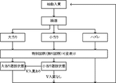
始動入賞の発生に基づいて、特図ゲームにおける特別図柄の可変表示結果となる特図表示結果を「大当り」や「小当り」、「ハズレ」のいずれとするかを決定するための抽選が行われる。こうした抽選結果に基づいて、特別図柄の可変表示が実行される。なお、特別図柄の可変表示が実行されることに対応(同期)して、画像表示装置5の表示領域において、飾り図柄の可変表示が行われるようにしてもよい。
Based on the occurrence of the start prize, a lottery is performed to determine whether the special figure display result, which is the variable display result of the special symbol in the special figure game, will be “big hit”, “small hit”, or “losing” Is called. Based on these lottery results, variable display of special symbols is executed. In addition, in response to the execution of variable display of special symbols (synchronization), variable display of decorative symbols may be performed in the display area of the
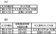
特図ゲームにおいて特図表示結果となる確定特別図柄が導出表示されて可変表示が終了すると、特図表示結果が特定表示結果としての「大当り」に決定されている場合には、遊技状態が特定遊技状態としての大当り遊技状態に制御される。大当り遊技状態では、予め定められた動作単位の特定動作となるラウンドが実行可能となる。特図表示結果が「大当り」となる場合には、例えばラウンドの実行形態に応じて、複数種類の大当り種別が設けられていてもよい。一例として、この実施の形態では、図8(A)に示すような「第1大当り」及び「第2大当り」の大当り種別が、予め用意されている。パチンコ遊技機1では、特別図柄表示装置4に表示される複数種類の特別図柄のうち、「3」及び「5」の数字を示す特別図柄を大当り図柄とし、大当り種別が「第1大当り」である場合には「3」の数字を示す特別図柄が確定特別図柄となる一方、大当り種別が「第2大当り」である場合には「5」の数字を示す特別図柄が確定特別図柄となるものとする。なお、大当り図柄となる特別図柄は任意に設定可能であり、「3」及び「5」の数字を示すものに限定されない。
In the special figure game, when the fixed special symbol that is the special figure display result is derived and displayed and the variable display is finished, the game state is specified when the special figure display result is determined as “big hit” as the specific display result It is controlled to the big hit gaming state as the gaming state. In the big hit gaming state, it is possible to execute a round that is a specific action of a predetermined action unit. When the special figure display result is “big hit”, a plurality of types of big hit types may be provided, for example, according to the execution form of the round. As an example, in this embodiment, big hit types of “first big hit” and “second big hit” as shown in FIG. 8A are prepared in advance. In the
特図表示結果が「大当り」で大当り種別が「第1大当り」に決定された場合には、大当り遊技状態において、特別可変入賞球装置7に設けられた大入賞口扉61によって開閉される大入賞口60が、遊技球の進入不可能な閉鎖状態から遊技球の進入可能な開放状態となる。一例として、大入賞口扉61は、大入賞口扉用ソレノイド54の駆動により、大入賞口60を閉鎖状態から開放状態へと変化させた後、所定時間(例えば29秒間)が経過したこと、あるいは所定個数(例えば9個)の入賞球が発生したことに応じて、大入賞口60を開放状態から閉鎖状態へと変化させる。こうした大入賞口60を閉鎖状態から開放状態とした後、再び閉鎖状態へと変化させるまでの動作単位が、1回のラウンドとして定められている。また、大当り遊技状態にてラウンドを繰り返し実行可能(継続可能)な最大継続回数としての大当り時ラウンド数(ラウンド最大値あるいは大入賞口最大開放回数とも称される)は、例えば「15」といった、予め定められた所定数であればよい。このように、特図表示結果が「大当り」で大当り種別が「第1大当り」となった場合には、可変入賞装置40に設けられた「左」及び「右」の役物進入口31L、31Rを開放状態とすることなく、特別可変入賞球装置7に設けられた大入賞口扉61により大入賞口60を開放状態とするラウンドが開始される。
When the special figure display result is “big hit” and the big hit type is determined to be “first big hit”, the big open /
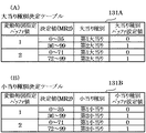
特図表示結果が「大当り」で大当り種別が「第2大当り」に決定された場合には、大当り遊技状態において、可変入賞装置40に設けられた「左」及び「右」の役物進入口31L、31Rが、遊技球の進入不可能な閉鎖状態から遊技球の進入可能な開放状態となる。一例として、「左」及び「右」の羽根部材32L、32Rは、開放ソレノイド53の駆動により、それぞれ「左」及び「右」の役物進入口31L、31Rを閉鎖状態から開放状態へと変化させた後、所定時間が経過したこと、あるいは所定個数の進入球が発生したことに応じて、「左」及び「右」の役物進入口31L、31Rを開放状態から閉鎖状態へと変化させる。こうした「左」及び「右」の役物進入口31L、31Rを閉鎖状態から開放状態とした後、再び閉鎖状態へと変化させるまでの動作単位が、1回のラウンドとして定められていればよい。あるいは、1回のラウンドとして、可変入賞装置40に設けられた「左」及び「右」の羽根部材32L、32Rにより、「左」及び「右」の役物進入口31L、31Rが遊技球の進入不可能な閉鎖状態から遊技球の進入可能な開放状態となった後に閉鎖状態へと戻る役物開閉動作が複数回繰り返されるようにしてもよい。
When the special figure display result is “big hit” and the big hit type is determined to be “second big hit”, the “left” and “right” bonus entrances provided in the variable winning
特図表示結果が開放表示結果としての「小当り」に決定された場合には、特図ゲームが終了した後に遊技状態が小当り遊技状態へと制御される。小当り遊技状態では、可変入賞装置40にて役物開閉動作が行われる。特図表示結果が「小当り」となる場合には、例えば役物開閉動作の実行形態やV入賞の発生に基づく大当り遊技状態におけるラウンドの実行内容(V入賞時ラウンド内容)に応じて、複数種類の小当り種別が設けられていてもよい。一例として、この実施の形態では、図8(B)に示すような「第1小当り」及び「第2小当り」の小当り種別が、予め用意されている。パチンコ遊技機1では、特別図柄表示装置4に表示される複数種類の特別図柄のうち、「1」及び「2」の数字を示す特別図柄を小当り図柄とし、小当り種別が「第1小当り」である場合には「1」の数字を示す特別図柄が確定特別図柄となる一方、小当り種別が「第2小当り」である場合には「2」の数字を示す特別図柄が確定特別図柄となるものとする。なお、小当り図柄となる特別図柄は任意に設定可能であり、「1」及び「2」の数字を示すものに限定されない。
When the special figure display result is determined to be “small hit” as the open display result, the gaming state is controlled to the small hit gaming state after the special figure game ends. In the small hit gaming state, the variable winning
特図表示結果が「小当り」で小当り種別が「第1小当り」に決定された場合には、小当り遊技状態において、役物開閉動作により「左」及び「右」の役物進入口31L、31Rが開放状態となる時間(役物開放時間)は、3秒であり、開放状態になる回数(開放回数)は、1回となっている。特図表示結果が「小当り」で小当り種別が「第2小当り」に決定された場合には、小当り遊技状態において、役物開閉動作による役物開放時間は1秒であり、開放回数は、例えば1秒間のインターバルを挟んで3回となっている。役物開閉動作が開始されるタイミングは、特図表示結果が所定時間(例えば1秒間)にわたり確定表示(導出表示)された後であればよい。
When the special figure display result is “small hit” and the small hit type is “first small hit”, the “left” and “right” bonuses are entered by opening and closing the bonus game in the small hit game state. The time for the
小当り遊技状態における役物開閉動作にて開放状態となった「左」及び「右」の役物進入口31L、31Rのいずれかより可変入賞装置40の内部に進入した遊技球が特定領域49に進入して特定領域スイッチ24によって検出された場合には、大当り遊技状態となる。ここで、可変入賞装置40の内部に進入した遊技球が上部ステージ33にて「中」の振分穴46Cに進入して「右」の上部球経路34Rに振り分けられた場合には、「左」及び「右」の振分穴46L、46Rのいずれかに進入して「左」の上部球経路34Lに振り分けられた場合に比べて、高い確率で特定領域49に進入し、特定領域スイッチ24によって検出される。すなわち、遊技球が「左」の上部球経路34Lに振り分けられた場合に比べて、「右」の上部球経路34Rに振り分けられた場合の方が、小当り遊技状態となった後に大当り遊技状態となる確率が高く、遊技者にとって有利になる。
A game ball that has entered the variable prize-winning
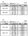
特図表示結果が「大当り」で大当り種別が「第2大当り」に決定された場合の大当り遊技状態で実行される1回目のラウンド(第1ラウンド)における役物開閉動作は、特図表示結果が「小当り」に決定された場合の小当り遊技状態で実行される役物開閉動作と、一部又は全部が同一の動作になるようにしてもよい。一例として、特図表示結果が「大当り」で大当り種別が「第2大当り」に決定された場合には、第1ラウンドでの役物開閉動作による開放時間は、3秒であり、開放回数は、例えば1秒間のインターバルを挟んで、最大で10回となるようにしてもよい。この場合には、第1ラウンドにおける1回目の役物開閉動作が、「第1小当り」の小当り種別に対応した小当り遊技状態における役物開閉動作と同一の動作になっている。他の一例として、特図表示結果が「大当り」で大当り種別が「第2大当り」に決定された場合には、第1ラウンドでの役物開閉動作による開放時間は、1秒であり、開放回数は、例えば1秒間のインターバルを挟んで、最大で30回となるようにしてもよい。この場合には、第1ラウンドにおける3回目までの役物開閉動作が、「第2小当り」の小当り種別に対応した小当り遊技状態における役物開閉動作と同一の動作になっている。なお、特図表示結果が「大当り」で大当り種別が「第2大当り」に決定された場合の大当り遊技状態では、第1ラウンドにおける役物開閉動作の一部又は全部が小当り遊技状態で実行される役物開閉動作と同一の動作となる一方で、例えば第2ラウンド以降は大入賞口扉61により大入賞口60を開放状態とするラウンドが実行されるといった、小当り遊技状態における役物開閉動作とは異なる動作が行われてもよい。
When the special figure display result is “big hit” and the big hit type is determined to be “second big hit”, the opening / closing operation of the accessory in the first round (first round) executed in the big hit gaming state is the special figure display result. Part or all may be the same operation as the accessory opening / closing operation executed in the small hit gaming state when is determined as “small hit”. As an example, when the special figure display result is determined to be “big hit” and the big hit type is determined to be “second big hit”, the opening time for the opening and closing operation of the accessory in the first round is 3 seconds, For example, it may be 10 times at maximum with an interval of 1 second. In this case, the first accessory opening / closing operation in the first round is the same as the accessory opening / closing operation in the small hit gaming state corresponding to the “first small hit” small hit type. As another example, when the special figure display result is determined to be “big hit” and the big hit type is determined to be “second big hit”, the opening time by the opening / closing operation of the accessory in the first round is 1 second. For example, the number of times may be 30 times at maximum with an interval of 1 second interposed therebetween. In this case, the accessory opening / closing operation up to the third time in the first round is the same operation as the accessory opening / closing operation in the small hit gaming state corresponding to the “second small hit” small hit type. In addition, in the big hit gaming state when the special figure display result is “big hit” and the big hit type is determined as “second big hit”, part or all of the opening / closing operation of the first round is executed in the small hit gaming state. On the other hand, in the second round and after, for example, a bonus game is performed in a small hit gaming state in which a round with the
小当り遊技状態における役物開閉動作により開放状態となった「左」及び「右」の役物進入口31L、31Rのいずれかから可変入賞装置40の内部に進入した遊技球(役物入賞球)が特定領域49を通過(進入)して特定領域スイッチ24によって検出されるとV入賞が発生する。V入賞が発生したときには、遊技状態が大当り遊技状態に制御される。この実施の形態において、小当り遊技状態に制御される際の小当り種別が「第1小当り」である場合に、V入賞の発生による大当り遊技状態でのV入賞時ラウンド内容は、特図表示結果が「大当り」で大当り種別が「第1大当り」に決定された場合と同様に、大入賞口60が開放状態となるラウンドが15回まで実行されるものとなる。これに対して、小当り遊技状態に制御される際の小当り種別が「第2小当り」である場合に、V入賞の発生による大当り遊技状態でのV入賞時ラウンド内容は、可変入賞装置40での役物開閉動作によるラウンドが15回まで実行されるものとなる。この小当り種別が「第2小当り」である場合に対応したV入賞時ラウンド内容は、特図表示結果が「大当り」で大当り種別が「第2大当り」に決定された場合における第2ラウンド以降と同様のものであればよい。
A game ball that has entered the inside of the variable winning
特図表示結果が「ハズレ」に決定された場合には、特図ゲームが終了した後に次の特図ゲームが実行可能になる。このとき、特図保留記憶数が「1」以上であれば、所定の確定図柄表示時間が経過した後、直ちに次の特図ゲームにおける特別図柄の可変表示が開始される。その一方で、特図保留記憶数が「0」である場合には、始動入賞の発生により始動条件が成立したときに、次の特図ゲームにおける特別図柄の可変表示が開始される。パチンコ遊技機1では、特別図柄表示装置4に表示される複数種類の特別図柄のうち、「0」の数字を示す特別図柄をハズレ図柄とし、特図表示結果が「ハズレ」である場合には「0」の数字を示す特別図柄が確定特別図柄となるものとする。なお、ハズレ図柄となる特別図柄は任意に設定可能であり、「0」の数字を示すものに限定されない。
When the special figure display result is determined to be “losing”, the next special figure game can be executed after the special figure game ends. At this time, if the special figure holding storage number is “1” or more, the variable symbol special symbol display in the next special symbol game is started immediately after a predetermined fixed symbol display time has elapsed. On the other hand, when the special figure holding storage number is “0”, when the start condition is established due to the occurrence of the start winning, the special symbol variable display in the next special figure game is started. In the
大当り遊技状態が終了した後には、特別遊技状態の1つとして、通常状態に比べて特図ゲームにおける特別図柄の変動時間(特図変動時間)が短縮される時間短縮制御(時短制御)が行われる時短状態に制御されることがあるようにしてもよい。ここで、通常状態とは、大当り遊技状態等の特定遊技状態や時短状態等の特別遊技状態以外の遊技状態のことであり、パチンコ遊技機1の初期設定状態(例えばシステムリセットが行われた場合のように、電源投入後に初期化処理を実行した状態)と同一の制御が行われる。時短状態は、所定回数(例えば100回)の特図ゲームが実行されることと、特図表示結果が「大当り」となることのうち、いずれかの条件が先に成立したときに、終了すればよい。 After the big hit game state is over, as one of the special game states, time reduction control (time reduction control) is performed in which the special symbol change time (special figure change time) in the special game is reduced compared to the normal state. It may be possible to control to a short state when it is displayed. Here, the normal state is a game state other than a special game state such as a big hit game state or a special game state such as a short-time state, and an initial setting state of the pachinko gaming machine 1 (for example, when a system reset is performed) Thus, the same control as in the state in which the initialization process is executed after power-on is performed. The time-saving state is terminated when one of the conditions is established first, that is, a predetermined number of times (for example, 100 times) of the special figure game is executed and the special figure display result is “big hit”. That's fine.
あるいは、大当り遊技状態が終了した後には、時短状態とは異なる特別遊技状態の1つとして、例えば通常状態に比べて特図変動時間が短縮される時間短縮制御とともに、継続して確率変動制御(確変制御)が行われる確変状態(高確率遊技状態)に制御されることがあるようにしてもよい。この確変状態では、各特図ゲームや飾り図柄の可変表示において、特図表示結果が「大当り」となって更に大当り遊技状態に制御される確率が、通常状態よりも高くなるように向上する。このような確変状態は、特図ゲームの実行回数に関わりなく、次に特図表示結果が「大当り」となるまで継続してもよい。これに対して、確変状態となった後に、所定回数(例えば100回)の特図ゲームが実行されることと、特図表示結果が「大当り」となることのうち、いずれかの条件が先に成立したときに、終了するようにしてもよい。また、確変状態において所定回数の特図ゲームが実行されたり特図表示結果が「大当り」となる以前であっても、特図ゲームが開始されるときに、所定の割合で確変状態が終了することがあるようにしてもよい。確変状態における時間短縮制御は、時短状態の場合と同様に、所定回数(例えば100回)の特図ゲームが実行されたときに、終了してもよい。あるいは、確変状態における時間短縮制御は、特図ゲームの実行回数にかかわりなく、次に特図表示結果が「大当り」となるまで継続してもよい。 Alternatively, after the big hit gaming state is ended, as one of the special gaming states different from the short-time state, for example, the probability variation control ( It may be controlled to a probability variation state (high probability gaming state) in which probability variation control is performed. In this probability change state, in the special display of each special figure game or decorative design, the special figure display result is “big hit”, and the probability of being further controlled to the big hit gaming state is improved to be higher than in the normal state. Such a probability change state may be continued until the special figure display result becomes “big hit” regardless of the number of executions of the special figure game. On the other hand, after the certainty change state is reached, any one of the conditions in which a predetermined number of times (for example, 100 times) the special figure game is executed and the special figure display result is “big hit” is first. It may be made to end when it is established. In addition, even if the special figure game is executed a predetermined number of times or the special figure display result is “big hit” in the probability change state, the probability change state ends at a predetermined rate when the special figure game is started. You may make it happen. Similar to the time-short state, the time reduction control in the probability changing state may be terminated when a predetermined number of times (for example, 100 times) of the special game is executed. Alternatively, the time reduction control in the probability variation state may be continued until the special figure display result becomes “big hit” next, regardless of the number of executions of the special figure game.
確変状態や時短状態にて時間短縮制御が行われるときには、普通図柄表示器20による普図ゲームにおける普通図柄の可変表示時間(普図変動時間)を通常状態のときよりも短くする制御や、各回の普図ゲームで普通図柄の可変表示結果が「普図当り」となる確率を通常状態のときよりも向上させる制御、可変表示結果が「普図当り」となったことに基づく普通可変入賞球装置6Bにおける可動翼片(開閉羽根)の傾動時間(開放時間)を通常状態のときよりも長くする制御、その傾動回数(開放回数)を通常状態のときよりも増加させる制御といった、第2始動入賞口に遊技球が進入する可能性を高めて第2始動条件が成立しやすくなることで遊技者にとって有利となる制御が行われてもよい。なお、これらの制御のいずれか1つが行われるようにしてもよいし、複数の制御が組み合わせられて行われるようにしてもよい。このように、確変状態や時短状態における時間短縮制御とともに、遊技球が第2始動入賞口に進入しやすくして遊技者にとって有利となる制御は、高開放制御ともいう。高開放制御が行われることにより、第2始動入賞口は、高開放制御が行われていないときよりも拡大開放状態となる頻度が高められる。これにより、第2特別図柄表示装置4Bにおける第2特図を用いた特図ゲームを実行するための第2始動条件が成立しやすくなり、特図ゲームが頻繁に実行可能となることで、次に特図表示結果が「大当り」となるまでの時間が短縮される。したがって、高開放制御が行われることにより、通常状態に比べて大当り遊技状態となりやすくなる。高開放制御が実行可能となる期間は、高開放制御期間ともいい、この期間は、パチンコ遊技機1における遊技状態が確変状態と時短状態のいずれかであるときに時間短縮制御が行われている期間と同一であればよい。
When the time shortening control is performed in the probability variation state or the short time state, the control for reducing the normal symbol variable display time (ordinary symbol variation time) in the ordinary symbol game by the ordinary
高開放制御期間であるときには、遊技状態が高ベース中であるともいう。これに対して、高開放制御期間でないときには、遊技状態が低ベース中であるともいう。この実施の形態における時短状態は、低確高ベース状態とも称される遊技状態であり、通常状態は、低確低ベース状態とも称される遊技状態である。また、確変状態において、高開放制御が行われる高開放制御期間であるときは、高確高ベース状態とも称される遊技状態であり、高開放制御期間でないときは、高確低ベース状態とも称される遊技状態である。 It is also said that the gaming state is in the high base during the high opening control period. On the other hand, when it is not the high opening control period, it is said that the gaming state is in the low base. The time-short state in this embodiment is a gaming state that is also referred to as a low probability and high base state, and the normal state is a gaming state that is also referred to as a low probability and low base state. Further, when the high opening control period during which the high opening control is performed in the probability changing state, the gaming state is also referred to as the high probability high base state, and when not in the high opening control period, it is also referred to as the high probability low base state. It is a gaming state to be played.
大当り遊技状態の終了後に時短状態や確変状態に制御されるか否かは、大当り遊技状態に制御された経緯や、大当り種別などに基づいて、決定されるようにしてもよい。一例として、小当り遊技状態における役物開閉動作にて開放状態となった「左」及び「右」の役物進入口31L、31Rのいずれかより可変入賞装置40の内部に進入した遊技球が特定領域49に進入するV入賞の発生に基づいて大当り遊技状態に制御された場合には、その大当り遊技状態の終了後に時短状態へと制御されるようにしてもよい。これに対して、特図表示結果が「大当り」となる直当りに基づいて大当り遊技状態に制御された場合には、その大当り遊技状態の終了後に確変状態へと制御されるようにしてもよい。他の一例として、大当り遊技状態でのV入賞時ラウンド内容が「第1大当り」の大当り種別に対応したものである場合には、その大当り遊技状態の終了後に時短状態へと制御されるようにしてもよい。これに対して、大当り遊技状態でのV入賞時ラウンド内容が「第2大当り」の大当り種別に対応したものである場合には、その大当り遊技状態の終了後に確変状態へと制御されるようにしてもよい。なお、大当り遊技状態の終了後に時短状態や確変状態といった特別遊技状態に制御されることがなく、遊技状態が通常状態となることがあるようにしてもよい。
Whether or not the state is controlled to the short-time state or the probable change state after the end of the big hit gaming state may be determined based on the background to the big hit gaming state, the type of big hit or the like. As an example, a game ball that has entered the variable prize-winning
この実施の形態では、大当り遊技状態の終了後に、所定回数(例えば100回など)の特図ゲームが実行されるまで、あるいは、特図表示結果が再び「大当り」となるまで、遊技状態が時短状態に制御されるものとする。その一方で、大当り遊技状態の終了後に、遊技状態が確変状態に制御されることはないものとして説明する。 In this embodiment, after the big hit game state is finished, the game state is shortened until a predetermined number of times (for example, 100 times) of the special figure game is executed or until the special figure display result becomes the “big hit” again. It shall be controlled by the state. On the other hand, it is assumed that the gaming state is not controlled to be a probable change state after the end of the big hit gaming state.
画像表示装置5の表示領域では、第1特別図柄表示装置4Aや第2特別図柄表示装置4Bによる特図ゲームにて特別図柄の可変表示が行われることに対応して、飾り図柄の可変表示が行われる。そして、特図ゲームでの確定特別図柄が大当り図柄となる場合には、飾り図柄の可変表示結果として、例えば「左」、「中」、「右」の各飾り図柄可変表示部にて所定の大当り組合せを構成する確定飾り図柄が停止表示される。また、特図ゲームでの確定特別図柄が小当り図柄となる場合には、飾り図柄の可変表示結果として、例えば「左」、「中」、「右」の各飾り図柄可変表示部にて所定の小当り組合せを構成する確定飾り図柄が停止表示される。一例として、大当り組合せの確定飾り図柄は、例えば「左」、「中」、「右」の各飾り図柄表示部5L、5C、5Rにて、同一の飾り図柄が揃って導出表示されるものであればよい。これに対して、小当り組み合わせの確定飾り図柄は、例えば「左」及び「右」の各飾り図柄表示部5L、5Rにて、同一の飾り図柄が揃って導出表示される一方で、「中」の飾り図柄表示部5Cにて、「左」及び「右」の飾り図柄表示部5L、5Rとは異なる飾り図柄が導出表示されるものであればよい。
In the display area of the
飾り図柄の可変表示中には、「左」、「中」、「右」の飾り図柄表示部5L、5C、5Rのうち全部又は一部の飾り図柄表示部にて、飾り図柄をリーチ表示状態で導出表示することがある。ここで、リーチ表示状態とは、画像表示装置5の表示領域にて導出表示された飾り図柄が大当り組合せの一部を構成しているときに未だ導出表示されていない飾り図柄(「リーチ変動図柄」ともいう)については変動が継続している表示状態、あるいは、全部又は一部の飾り図柄が大当り組合せの全部又は一部を構成しながら同期して変動している表示状態のことである。具体的には、「左」、「中」、「右」の飾り図柄表示部5L、5C、5Rにおける一部(例えば「左」及び「右」の飾り図柄表示部5L、5Rなど)では予め定められた大当り組合せを構成する飾り図柄(例えば「7」の英数字を示す飾り図柄)が導出表示されているときに未だ導出表示されていない残りの飾り図柄表示部(例えば「中」の飾り図柄表示部5Cなど)では飾り図柄が変動している表示状態、あるいは、「左」、「中」、「右」の飾り図柄表示部5L、5C、5Rにおける全部又は一部で飾り図柄が大当り組合せの全部又は一部を構成しながら同期して変動している表示状態である。また、リーチ表示状態となったことに対応して、画像表示装置5の表示領域に飾り図柄とは異なるアニメーション画像や実写画像といった演出画像を表示させたり、背景画像の表示態様を変化させたり、飾り図柄の変動態様を変化させたりすることがある。このような演出画像の表示や背景画像の表示態様の変化、飾り図柄の変動態様の変化を、リーチ演出表示(あるいは単にリーチ演出)という。リーチ演出の中には、それが出現すると、通常のリーチ演出(ノーマルリーチ)に比べて大当りが発生しやすい(高い確率で大当りとなる)ように設定されたものがある。このような特別のリーチ演出を、スーパーリーチ演出(あるいは単に「スーパーリーチ」)ともいう。一例として、スーパーリーチとなるリーチ演出には、ノーマルリーチと同様のリーチ演出を所定時間が経過するまで行ってから、例えば背景画像の表示態様や、表示されるキャラクタ、飾り図柄の変動方向といった飾り図柄の変動態様のうち、少なくともいずれか1つがリーチ表示状態となる以前やノーマルリーチのときとは異なるものとなることにより、演出態様が変化(いわゆる「発展」)して、スーパーリーチに特有のリーチ演出における導入部分が開始されるものが含まれていればよい。また、スーパーリーチとなるリーチ演出には、飾り図柄がリーチ表示状態で導出表示されたときに、ノーマルリーチと同様のリーチ演出を行うことなく、スーパーリーチに特有のリーチ演出における導入部分が開始されるものが含まれていてもよい。
During the variable display of the decorative symbols, the decorative symbols are in a reach display state on all or some of the decorative
また、飾り図柄の可変表示中には、リーチ演出とは異なり、飾り図柄がリーチ状態で導出表示される可能性があることや、可変表示結果が「大当り」となる可能性があることを、飾り図柄の可変表示態様などにより遊技者に報知するための特定演出が実行されることがある。この実施の形態では、「滑り」や「擬似連」といった特定演出が実行可能に設定されている。なお、この実施の形態における特定演出は、対応する演出動作が実行されるか否か応じて特図変動時間が変化するものであればよい。例えば、ある特定演出が実行される場合には、その特定演出が実行されない場合に比べて、特図変動時間が長くなるものであればよい。 In addition, during the variable display of decorative symbols, unlike reach production, there is a possibility that the decorative symbols may be derived and displayed in the reach state, and that the variable display result may be a “hit”, There may be a case where a specific effect for informing the player is given in accordance with a variable display mode of the decorative design. In this embodiment, specific effects such as “slip” and “pseudo-run” are set to be executable. In addition, the specific effect in this embodiment should just change a special figure fluctuation time according to whether a corresponding effect operation is performed. For example, when a specific effect is executed, it is only necessary that the special figure change time becomes longer than when the specific effect is not executed.
「滑り」の特定演出では、「左」、「中」、「右」の飾り図柄表示部5L、5C、5Rにおける全部にて飾り図柄を変動させる全図柄変動を行ってから、2つ以上の飾り図柄表示部(例えば「左」及び「右」の飾り図柄表示部5L、5Rなど)にて飾り図柄を仮停止表示させた後、その仮停止表示した飾り図柄表示部のうち所定数(例えば「1」又は「2」)の飾り図柄表示部(例えば「左」の飾り図柄表示部5Lと「右」の飾り図柄表示部5Rのいずれか一方又は双方)にて飾り図柄を再び変動させた後に停止表示させることで、停止表示する飾り図柄を変更させる演出表示が行われる。なお、特定演出における飾り図柄の仮停止表示では、飾り図柄が停留して表示される一方で、例えば揺れ変動表示を行うことや短時間の停留だけで直ちに飾り図柄を再変動させることなどによって、遊技者に停止表示された飾り図柄が確定しない旨を報知すればよい。あるいは、仮停止表示でも、停止表示された飾り図柄が確定したと遊技者が認識する程度に飾り図柄を停留させてから、飾り図柄を再変動させるようにしてもよい。
In the specific effect of “sliding”, after performing all symbol variations that change the ornament symbols in all of the “left”, “middle”, and “right” ornament
「擬似連」の特定演出では、特別図柄や飾り図柄の可変表示を開始するための第1開始条件あるいは第2開始条件が1回成立したことに対応して、全図柄変動が開始されてから、「左」、「中」、「右」の飾り図柄表示部5L、5C、5Rの全部にて順次に又は同時に飾り図柄を仮停止表示させた後、「左」、「中」、「右」の飾り図柄表示部5L、5C、5Rの全部にて飾り図柄を再び変動させる再可変表示動作(再変動)を、所定回(例えば最大3回まで)実行する演出動作である。一例として、「擬似連」の特定演出では、「左」、「中」、「右」の飾り図柄表示部5L、5C、5Rにて、擬似連チャンス目として予め定められた複数種類の飾り図柄の組合せのいずれかが仮停止表示される。そして、再変動の回数が多くなるに従って、可変表示結果が「大当り」となる割合が高くなるように設定されていればよい。これにより、遊技者は、擬似連チャンスのいずれかが仮停止表示されることで、「擬似連」の特定演出が行われると認識でき、再変動の回数が多くなるに従って、可変表示結果が「大当り」となる期待感が高められる。この実施の形態では、「擬似連」の特定演出において、再変動が1回〜3回行われることにより、第1開始条件あるいは第2開始条件が1回成立したことに基づき、飾り図柄の可変表示があたかも2回〜4回続けて開始されたかのように見せることができる。
In the “pseudo-ream” specific production, all symbol fluctuations are started in response to the first start condition or the second start condition for starting the variable display of special symbols and decorative symbols being established once. , “Left”, “Medium”, “Right” decorative symbols are displayed on all 5 L, 5 C, 5 R sequentially or simultaneously, and then “Left”, “Middle”, “Right” "Revariable display operation (revariation) for changing the decorative symbols again in all of the decorative
「擬似連」の特定演出が実行される飾り図柄の可変表示中には、擬似連続変動の進行に伴って、例えば画像表示装置5の表示領域における所定位置に予め用意されたキャラクタを示す演出画像を表示することや、スピーカ8L、8Rから所定の音声(特別音)を出力させること、遊技効果ランプ9を所定の点灯パターンで点灯させること、遊技領域内あるいは遊技領域外に設けられた演出用役物が備える複数の可動部材を動作させることといった、所定の演出動作が実行されてもよい。一例として、全部の飾り図柄表示部5L、5C、5Rにて飾り図柄を仮停止表示させた後、全部の飾り図柄表示部5L、5C、5Rにて飾り図柄を再可変表示させるときには、キャラクタを示す演出画像の表示、特別音の出力、ランプの点灯、可動部材の動作のうち、いずれか1つ、あるいは、複数の動作を組み合わせた演出動作が行われることにより、擬似連続変動が行われることを認識可能に報知するようにしてもよい。
During the variable display of the decorative pattern in which the specific effect of “pseudo-continuation” is executed, an effect image showing a character prepared in advance at a predetermined position in the display area of the
こうした飾り図柄の可変表示動作を利用した特定演出としては、「擬似連」や「滑り」の他にも、例えば「発展チャンス目」や「発展チャンス目終了」、「チャンス目停止後滑り」といった、各種の演出動作が実行されてもよい。ここで、「発展チャンス目」の特定演出では、飾り図柄の可変表示が開始されてから可変表示結果となる確定飾り図柄が導出表示されるまでに、「左」、「中」、「右」の飾り図柄表示部5L、5C、5Rにおける全部にて、予め定められた特殊組合せに含まれる発展チャンス目を構成する飾り図柄を仮停止表示させた後、飾り図柄の可変表示状態をリーチ状態として所定のリーチ演出が開始される。これにより、発展チャンス目を構成する飾り図柄が仮停止表示されたときには、飾り図柄の可変表示状態がリーチ状態となることや、リーチ状態となった後に可変表示結果が「大当り」となることに対する、遊技者の期待感が高められる。また、「発展チャンス目終了」の特定演出では、飾り図柄の可変表示が開始された後に、「左」、「中」、「右」の飾り図柄表示部5L、5C、5Rにおける全部にて、発展チャンス目として予め定められた組合せの飾り図柄を、確定飾り図柄として導出表示させる演出表示が行われる。「チャンス目停止後滑り」の特定演出では、「擬似連」の可変表示演出と同様に、飾り図柄の可変表示が開始されてから可変表示結果となる確定飾り図柄が導出表示されるまでに、「左」、「中」、「右」の飾り図柄表示部5L、5C、5Rにおける全部にて複数種類の擬似連チャンス目のいずれかとなるハズレ組合せ(特殊組合せ)の飾り図柄を一旦仮停止表示させた後、「擬似連」の特定演出とは異なり、飾り図柄表示部5L、5C、5Rの一部にて飾り図柄を再び変動させることで、停止表示する飾り図柄を変更させる演出表示が行われる。
In addition to “pseudo-continuous” and “slip”, specific effects using such decorative display variable display operations include, for example, “Development opportunity eyes”, “Development opportunity eyes end”, and “Slip after chance eyes stop” Various production operations may be executed. Here, in the specific effect of “Development Opportunity”, “Left”, “Middle”, “Right” from the start of the variable display of the decorative pattern to the display of the fixed decorative pattern resulting in the variable display result. In all of the decorative
さらに、飾り図柄の可変表示中には、リーチ演出や特定演出とは異なり、例えば所定のキャラクタ画像やメッセージ画像を表示することなどといった、飾り図柄の可変表示態様以外の表示態様により、飾り図柄の可変表示状態がリーチ状態となる可能性があることや、可変表示結果が「大当り」となる可能性があることを、遊技者に報知するための予告演出が実行されることがある。例えば、「キャラクタ表示」、「ステップアップ画像」、「背景変更」といった予告演出が実行可能に設定されていればよい。なお、予告演出は、対応する演出動作が実行されるか否かによって特図変動時間に変化が生じないものであればよい。「キャラクタ表示」の予告演出では、「左」、「中」、「右」の各飾り図柄表示部5L、5C、5Rにおける全部にて飾り図柄を変動させてから、2つ以上の飾り図柄表示部(例えば「左」及び「右」の飾り図柄表示部5L、5Rなど)にて飾り図柄を導出表示させる以前に、画像表示装置5の表示領域における所定位置に予め用意されたキャラクタ画像を表示させる演出表示が行われる。「ステップアップ画像」の予告演出では、「左」、「中」、「右」の各飾り図柄表示部5L、5C、5Rにおける全部にて飾り図柄を変動させてから、2つ以上の飾り図柄表示部にて飾り図柄を導出表示させる以前に、画像表示装置5の表示領域にて、予め用意された複数種類の演出画像を所定の順番に従って切り替えて表示させる演出表示が行われることがある。なお、「ステップアップ画像」の予告演出では、予め用意された複数種類の演出画像のうちいずれか1つ(例えば所定の順番において最初に表示される演出画像など)が表示された後、演出画像が切り替えられることなく、予告演出における演出表示を終了させることがあるようにしてもよい。「背景変更」の予告演出では、画像表示装置5の表示領域における背景画像の表示を、複数種類のいずれかに変更させる演出表示が行われる。
Furthermore, during the variable display of the decorative pattern, unlike the reach effect or the specific effect, for example, by displaying the decorative pattern in a display mode other than the variable display mode of the decorative pattern, such as displaying a predetermined character image or message image. A notice effect may be executed to notify the player that the variable display state may become a reach state and that the variable display result may be a “hit”. For example, the notice effect such as “character display”, “step-up image”, and “background change” may be set to be executable. Note that the notice effect may be any one that does not change in the special figure fluctuation time depending on whether or not the corresponding effect operation is executed. In the notice effect of “character display”, two or more decorative symbols are displayed after the decorative symbols are changed in all of the “left”, “middle”, and “right” decorative
また、複数回の特図ゲームなどに対応して複数回実行される飾り図柄の可変表示にわたり、可変表示結果が「大当り」となる可能性があることや、特定の変動パターン(例えばスーパーリーチを伴う変動パターン)による可変表示が実行される可能性があることなどを、遊技者に認識させるように報知するための予告演出が、連続して実行されることがある。このような複数回の可変表示にわたり連続して実行される予告演出を、連続予告演出ともいう。これに対して、単一の可変表示に対応して実行される予告演出を、単独予告演出ともいう。連続予告演出が実行される複数回の可変表示のうちで最終の可変表示は、連続予告演出により可変表示結果が「大当り」となる可能性などが報知される対象となる可変表示であり、連続予告演出による予告対象となる可変表示ともいう。連続予告演出が実行される場合には、予告対象となる可変表示が開始されるより前に、特図ゲームの保留記憶情報に基づいて可変表示結果が「大当り」となる可能性などを予告する予告演出が開始される。 In addition, there is a possibility that the variable display result may be a “hit” over the variable display of decorative symbols executed multiple times in response to multiple special drawing games, etc. A notice effect for informing the player that the variable display by the accompanying fluctuation pattern) may be executed may be continuously executed. Such a notice effect continuously executed over a plurality of variable displays is also referred to as a continuous notice effect. On the other hand, the notice effect performed in response to a single variable display is also referred to as a single notice effect. The last variable display among the multiple variable displays for which the continuous notice effect is executed is a variable display for which the possibility of the variable display result being a “big hit” is notified by the continuous notice effect. It is also referred to as a variable display that is subject to notice by a notice effect. When the continuous notice effect is executed, the possibility that the variable display result will be a “hit” based on the reserved memory information of the special figure game is notified before the variable display to be notified is started. The notice effect is started.
連続予告演出が開始された後には、例えば飾り図柄の可変表示が実行されるごとに、予め用意された複数種類の演出画像を所定の順番に従って選択的に表示させる演出表示により、演出態様が複数段階に変化(ステップアップ)するような演出動作が行われるようにしてもよい。このとき、変化する回数(ステップ数)が多くなるに従って、可変表示結果が「大当り」となる可能性(信頼度)などが高くなるようにしてもよい。さらに変化する回数(ステップ数)によって予告する対象が変化するようにしてもよい。例えば第2ステップまで行くと「リーチ確定」、第3ステップまで行くと「スーパーリーチ確定」、第4ステップまで行くと「大当り確定」となるようなものでもよい。予告の態様の変化(ステップアップ)としては、異なるキャラクタ画像が順番に表示されるものであってもよいし、1つのキャラクタにおける形状や色等が変化することでステップアップするようなものであってもよい。すなわち、遊技者からみて予告する手段(表示、音、ランプ、可動物等)の状態が段階的に変化したと認識可能なものであればよい。 After the continuous notice effect is started, for example, every time variable display of decorative symbols is executed, a plurality of effect modes are provided by effect display that selectively displays a plurality of types of effect images prepared in advance in a predetermined order. An effect operation that changes (steps up) in stages may be performed. At this time, as the number of times of change (number of steps) increases, the possibility (reliability) of the variable display result to be a “big hit” may be increased. Further, the object to be notified may change depending on the number of times of change (number of steps). For example, “reach determination” may be performed when going to the second step, “super reach confirmation” when going to the third step, and “big hit confirmation” going to the fourth step. As the change of the notice mode (step-up), different character images may be displayed in order, or the step-up may be performed by changing the shape or color of one character. May be. That is, it is only necessary to be able to recognize that the state of the notice means (display, sound, lamp, movable object, etc.) as viewed from the player changes stepwise.
特図ゲームにおける確定特別図柄として、ハズレ図柄となる特別図柄が停止表示される場合には、飾り図柄の可変表示が開始されてから、飾り図柄の可変表示状態がリーチ状態とならずに、所定の非リーチ組合せとなる確定飾り図柄や、複数種類の発展チャンス目のいずれかとなる確定飾り図柄が、停止表示されることがある。このような飾り図柄の可変表示態様は、可変表示結果が「ハズレ」となる場合における「非リーチ」(「通常ハズレ」ともいう)の可変表示態様と称される。 If a special symbol that will be a lost symbol is stopped and displayed as a special symbol to be confirmed in the special symbol game, the decorative symbol variable display state will not reach the reach state after the variable symbol variable display starts. There are cases where a fixed decorative symbol that is a non-reach combination or a fixed decorative symbol that is one of a plurality of types of development chances is stopped and displayed. Such a decorative display variable display mode is referred to as a “non-reach” (also referred to as “normal loss”) variable display mode when the variable display result is “losing”.
特図ゲームにおける確定特別図柄として、ハズレ図柄となる特別図柄が停止表示される場合には、飾り図柄の可変表示が開始されてから、飾り図柄の可変表示状態がリーチ状態となったことに対応して、リーチ演出が実行された後に、所定のリーチハズレ組合せ(単に「リーチ組合せ」ともいう)となる確定飾り図柄が停止表示されることがある。このような飾り図柄の可変表示結果は、可変表示結果が「ハズレ」となる場合における「リーチ」(「リーチハズレ」ともいう)の可変表示態様と称される。 When a special symbol that becomes a losing symbol is stopped and displayed as a confirmed special symbol in the special symbol game, it corresponds to the fact that the decorative symbol variable display state has reached the reach state after the decorative symbol variable display has started. Then, after the reach effect is executed, a fixed decorative pattern that becomes a predetermined reach-losing combination (also simply referred to as “reach combination”) may be stopped and displayed. Such a variable display result of the decorative design is referred to as a variable display mode of “reach” (also referred to as “reach lose”) when the variable display result is “losing”.
確変状態では、例えば「確変中」といった確変状態であることを報知する演出画像を画像表示装置5の表示領域に表示させることや、画像表示装置5の表示領域における背景画像や飾り図柄の表示態様を通常の演出モードにおける表示態様とは異なるものとすることなどにより、確変状態であることを遊技者が認識できる確変中の演出モードとなるようにしてもよい。あるいは、確変状態では、例えば通常状態や時短状態と同様の演出モードとなることにより、確変状態であることを遊技者が認識不可能あるいは認識困難になることがあってもよい(いわゆる潜伏確変)。こうした潜伏確変が行われる期間は、遊技状態が潜伏確変中であるともいう。
In the probability variation state, for example, an effect image for notifying that the probability variation state is “being probability variation” is displayed in the display area of the
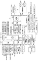
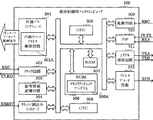
パチンコ遊技機1には、例えば図9に示すような電源基板10、主基板11、演出制御基板12、音声制御基板13、ランプ制御基板14、払出制御基板15、発射制御基板17といった、各種の制御基板が搭載されている。また、パチンコ遊技機1には、主基板11と演出制御基板12との間で伝送される各種の制御信号を中継するための中継基板18なども搭載されている。なお、音声制御基板13やランプ制御基板14は、演出制御基板12とは別個の独立した基板によって構成されてもよいし、演出制御基板12にまとめられて1つの基板として構成されてもよい。その他、パチンコ遊技機1の背面には、例えば情報端子基板やインタフェース基板などといった、各種の制御基板が配置されている。インタフェース基板は、パチンコ遊技機1に隣接してカードユニットが設置される場合に、払出制御基板15とカードユニットとの間に介在する制御基板である。
The
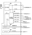
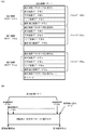
電源基板10は、主基板11、演出制御基板12、払出制御基板15等の各制御基板とは独立して設置され、パチンコ遊技機1内の各制御基板及び機構部品が使用する電圧を生成する。例えば、電源基板10では、図10に示すように、AC24V、VLP(直流+24V)、VSL(直流+30V)、VDD(直流+12V)、VCC(直流+5V)及びVBB(直流+5V)を生成する。電源基板10は、例えば図10に示すように、変圧回路301と、直流電圧生成回路302と、電源監視回路303と、クリアスイッチ304とを備えて構成されている。また、電源基板10には、バックアップ電源となるコンデンサが設けられていてもよい。このコンデンサは、例えばVBB(直流+5V)の電源ラインから充電されるものであればよい。加えて、電源基板10には、パチンコ遊技機1内の各制御基板及び機構部品への電力供給を実行又は遮断するための電源スイッチが設けられていてもよい。あるいは、電源スイッチは、パチンコ遊技機1において、電源基板10の外部に設けられていてもよい。
The
変圧回路301は、例えば商用電源が入力側(一次側)に印加されるトランスや、トランスの入力側に設けられた過電圧保護回路としてのバリスタなどを備えて構成されたものであればよい。ここで、変圧回路301が備えるトランスは、商用電源と電源基板10の内部とを電気的に絶縁するためのものであればよい。変圧回路301は、その出力電圧として、AC24Vを生成する。直流電圧生成回路302は、例えばAC24Vを整流素子で整流昇圧することによってVSLを生成する整流平滑回路を含んでいる。VSLは、ソレノイド駆動用の電源電圧として用いられる。また、直流電圧生成回路302は、例えばAC24Vを整流素子で整流することによってVLPを生成する整流回路を含んでいる。VLPは、遊技効果ランプ9等の発光体を点灯するための電源電圧として用いられる。加えて、直流電圧生成回路302は、例えばVSLに基づいてVDDおよびVCCを生成するDC−DCコンバータを含んでいる。このDC−DCコンバータは、例えば1つ又は複数のスイッチングレギュレータと、そのスイッチングレギュレータの入力側に接続された比較的大容量のコンデンサとを含み、外部からパチンコ遊技機1への電力供給が停止したときに、VSL、VDD、VBB等の直流電圧が比較的緩やかに低下するように構成されたものであればよい。VDDは、例えば図4に示すゲートスイッチ21、第1及び第2始動口スイッチ22A、22B、役物カウントスイッチ23L、23C、23R、特定領域スイッチ24、排出口スイッチ25、一般入賞口スイッチ27F、27L、27R、大入賞口カウントスイッチ28といった、遊技媒体を検出する各種スイッチに供給され、これらのスイッチを作動させるために用いられる。
For example, the
図10に示すように、変圧回路301から出力されたAC24Vは、例えば所定のコネクタや電源ラインを介して、払出制御基板15へと伝送される。VLPは、例えば所定のコネクタや電源ラインを介して、ランプ制御基板14へと伝送される。VSL、VDD及びVCCは、例えば所定のコネクタや電源ラインを介して、主基板11、ランプ制御基板14及び払出制御基板15へと伝送される。VBBは、例えば所定のコネクタや電源ラインを介して、主基板11及び払出制御基板15へと伝送される。なお、演出制御基板12及び音声制御基板13には、ランプ制御基板14を経由して各電圧が供給されればよい。あるいは、演出制御基板12及び音声制御基板13には、ランプ制御基板14を経由することなく、電源基板10から直接に各電圧が供給されてもよい。
As shown in FIG. 10, AC24V output from the
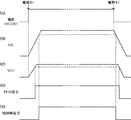
電源監視回路303は、例えば停電監視リセットモジュールICを用いて構成され、電源断信号を出力する電源監視手段を実現する回路である。例えば、電源監視回路303は、パチンコ遊技機1において用いられる所定電源電圧(一例としてVSL)が所定値(一例として+22V)を超えると、オフ状態(ハイレベル)の電源断信号を出力する。その一方で、所定電源電圧が所定値以下になった期間が、予め決められている時間(一例として56ms)以上継続したときに、オン状態(ローレベル)の電源断信号を出力する。あるいは、電源監視回路303は、パチンコ遊技機1において用いられる所定電源電圧が所定値以下になると、直ちにオン状態の電源断信号を出力するようにしてもよい。電源断信号は、例えばローレベルとなることでオン状態となりハイレベルとなることでオフ状態となる負論理の電気信号であればよい。電源監視回路303から出力された電源断信号は、例えば電源基板10に搭載された出力ドライバ回路によって増幅された後に所定のコネクタや信号ラインを介して、主基板11や払出制御基板15へと伝送される。なお、電源断信号は、払出制御基板15を介して主基板11へと伝送されるようにしてもよい。
The
電源断信号を出力するための監視対象となる所定電源電圧は、例えば電源電圧VSLといった、スイッチ作動用の電源電圧VDDにおける規定値(一例として+12V)よりも高い電圧であることが好ましい。これにより、スイッチ作動用の電源電圧VDDが低下して各種スイッチ(例えばゲートスイッチ21、第1及び第2始動口スイッチ22A、22B、役物カウントスイッチ23L、23C、23R、特定領域スイッチ24、排出口スイッチ25、一般入賞口スイッチ27F、27L、27R、大入賞口カウントスイッチ28など)の動作状態が不安定となる以前に、電源断信号を出力する(オン状態にする)ことで、各種スイッチによる誤検出に基づく遊技制御の進行を防止できる。すなわち、スイッチ作動用の電源電圧VDDが低下すると負論理(ローレベルでオン状態となる)のスイッチ出力がオン状態となるものの、電源電圧VDDよりも早く低下する電源電圧VSLを監視して電力供給の停止を認識することで、スイッチ出力がオン状態となる以前に、電源復旧待ちの状態となってスイッチ出力を検出しない状態となることができる。
The predetermined power supply voltage to be monitored for outputting the power-off signal is preferably a voltage higher than a specified value (for example, +12 V) in the power supply voltage VDD for operating the switch, such as the power supply voltage VSL. As a result, the power supply voltage VDD for operating the switch decreases, and various switches (for example, the
電源電圧VSLなどを主基板11、ランプ制御基板14及び払出制御基板15へと伝送する電源ラインには、大容量のコンデンサが接続されていてもよい。これに対して、電源電圧VSLを監視対象とするために電源監視回路303へと伝送する入力ラインには、このようなコンデンサが接続されていなくてもよい。この場合、監視対象となる電源監視回路303への入力ラインにおける電源電圧VSLは、コンデンサが接続された電源ラインにおける電源電圧VSLより早く低下する。すなわち、監視対象の電源電圧VSLが低下し始めた後でも、所定期間は、ソレノイドやモータなどに供給される電源ラインにおける電源電圧VSLの供給状態が維持される。したがって、監視対象となる電源電圧VSLが低下し始める場合でも、所定期間は、ソレノイドやモータなどを駆動可能な状態とすることができる。また、電源ラインにおける電源電圧VSLが低下し始める前に、電力供給の停止を認識することができる。
A large capacity capacitor may be connected to the power supply line for transmitting the power supply voltage VSL and the like to the
なお、ソレノイド駆動用の電源電圧VSLに代えて、例えば発光体点灯用の電源電圧VLPといった、スイッチ作動用の電源電圧VDDにおける規定値よりも高い任意の電源電圧を監視対象として、電源断信号を出力するようにしてもよい。また、外部からパチンコ遊技機1に供給される電力の供給停止を検出するための条件としては、パチンコ遊技機1において用いられる所定電源電圧が所定値以下になったことに限られず、外部からの電力が途絶えたことを検出できる任意の条件であればよい。例えば、AC24V等の交流波そのものを監視して交流波が途絶えたことを検出条件としてもよいし、交流波をデジタル化した信号を監視して、デジタル信号が平坦になったことをもって交流波が途絶えたことの検出条件としてもよい。
In place of the solenoid drive power supply voltage VSL, for example, a power cut-off signal is generated by monitoring an arbitrary power supply voltage higher than a specified value in the switch operation power supply voltage VDD, for example, the power supply voltage VLP for lighting the light emitter. You may make it output. In addition, the condition for detecting the stop of the supply of power supplied to the
電源監視回路303は、例えば所定電源電圧(一例としてVCC)が所定値(一例として+4.5V)以下になったときに、リセット信号を出力してもよい。リセット信号は、例えばローレベルとなることでオン状態となる電気信号であればよい。電源監視回路303から出力されたリセット信号は、例えば電源基板10に搭載された出力ドライバ回路によって増幅された後に所定のコネクタや信号ラインを介して、主基板11、ランプ制御基板14及び払出制御基板15へと伝送される。演出制御基板12には、ランプ制御基板14を経由してリセット信号が伝送されればよい。あるいは、演出制御基板12に対しても、ランプ制御基板14を経由せずにリセット信号が直接に伝送されるようにしてもよい。さらに、リセット信号を出力する回路は、電源監視回路303とは別個に設けられたウォッチドッグタイマ内蔵IC、あるいはシステムリセットICなどを用いて構成されてもよい。
For example, the power
パチンコ遊技機1への電力供給が停止するときには、電源監視回路303が、電源断信号を出力(ローレベルに設定)してから所定期間が経過したときに、リセット信号を出力(ローレベルに設定)する。ここでの所定期間は、例えば図4に示す主基板11に搭載されている遊技制御用マイクロコンピュータ100及び払出制御基板15に搭載されている払出制御用マイクロコンピュータ150が、所定の電源断処理を実行するのに十分な時間であればよい。すなわち、電源監視回路303は、給電中信号としての電源断信号を出力した後、遊技制御用マイクロコンピュータ100及び払出制御用マイクロコンピュータ150が所定の電源断処理を実行完了してから、動作停止信号としてのリセット信号を出力(ローレベルに設定)する。電源監視回路303から出力されたリセット信号を受信した遊技制御用マイクロコンピュータ100や払出制御用マイクロコンピュータ150は、動作停止状態となり、各種の制御処理の実行が停止される。また、パチンコ遊技機1への電力供給が開始され、例えば所定電源電圧(一例としてVCC)が所定値(一例として+4.5V)を超えたときに、電源監視回路303はリセット信号の出力を停止(ハイレベルに設定)する。
When the power supply to the
図11は、パチンコ遊技機1への電力供給が開始されたとき、及び電力供給が停止するときにおける、AC24V、VSL、VCC、リセット信号及び電源断信号の状態を、模式的に示すタイミング図である。図6に示すように、パチンコ遊技機1への電力供給が開始されたときに、VSL及びVCCは徐々に規定値(直流+30V及び直流+5V)に達する。このとき、VCCが第1の所定値を超えると、電源監視回路303はリセット信号の出力を停止(ハイレベルに設定)してオフ状態とする。また、VSLが第2の所定値を超えると、電源監視回路303は電源断信号の出力を停止(ハイレベルに設定)してオフ状態とする。他方、パチンコ遊技機1への電力供給が停止するときに、VSL及びVCCは徐々に低下する。このとき、VSLが第2の所定値にまで低下すると、電源監視回路303は電源断信号をオン状態として出力(ローレベルに設定)する。また、VCCが第1の所定値にまで低下すると、電源監視回路303はリセット信号をオン状態として出力(ローレベルに設定)する。
FIG. 11 is a timing diagram schematically showing the states of AC 24 V, VSL, VCC, reset signal, and power-off signal when power supply to the
図10に示す電源基板10が備えるクリアスイッチ304は、例えば押しボタン構造を有し、押下などの操作に応じてクリア信号を出力する。クリア信号は、例えば押下などの操作に応じてローレベルとなることでオン状態となる電気信号であればよい。あるいは、クリア信号は、例えば押下などの操作に応じてハイレベルとなることでオン状態となる電気信号であってもよい。クリアスイッチ304から出力されたクリア信号は、例えば所定のコネクタや信号ラインを介して、主基板11へと伝送され、主基板11から払出制御基板15へと伝送される。また、クリアスイッチ304の操作がなされていないときには、クリア信号の出力を停止(ハイレベルあるいはローレベルに設定)する。なお、クリアスイッチ304は、押しボタン構造以外の他の構成(例えばスライドスイッチ構造やトグルスイッチ構造、ダイヤルスイッチ構造など)であってもよい。
A
主基板11は、メイン側の制御基板であり、パチンコ遊技機1における遊技の進行を制御するための各種回路が搭載されている。主基板11は、主として、特図ゲームにおいて用いる乱数の設定機能、所定位置に配設されたスイッチ等からの信号の入力を行う機能、演出制御基板12や払出制御基板15などからなるサブ側の制御基板に宛てて、指令情報の一例となる制御コマンドを制御信号として出力して送信する機能、ホールの管理コンピュータに対して各種情報を出力する機能などを備えている。また、主基板11は、第1特別図柄表示装置4Aと第2特別図柄表示装置4Bを構成する各LED(例えばセグメントLED)などの点灯/消灯制御を行って第1特図や第2特図の可変表示を制御することや、普通図柄表示器20の点灯/消灯/発色制御などを行って普通図柄表示器20による普通図柄の可変表示を制御することといった、所定の表示図柄の可変表示を制御する機能も備えている。主基板11は、例えば図9に示すように、遊技制御用マイクロコンピュータ100と、制御用クロック生成回路111と、乱数用クロック生成回路112と、スイッチ回路114と、ソレノイド回路115と、モータ駆動回路116を備えている。また、主基板11には、遊技開始スイッチ31が設置されていてもよい。
The
ここで、制御用クロック生成回路111は、遊技制御用マイクロコンピュータ100の外部にて、所定周波数の発振信号となる制御用クロックCCLKを生成する。制御用クロック生成回路111により生成された制御用クロックCCLKは、例えば図13に示すような遊技制御用マイクロコンピュータ100の制御用外部クロック端子EXCを介してクロック回路502に供給される。乱数用クロック生成回路112は、遊技制御用マイクロコンピュータ100の外部にて、制御用クロックCCLKの発振周波数とは異なる所定周波数の発振信号となる乱数用クロックRCLKを生成する。乱数用クロック生成回路112により生成された乱数用クロックRCLKは、例えば図13に示すような遊技制御用マイクロコンピュータ100の乱数用外部クロック端子ERCを介して乱数回路509に供給される。一例として、乱数用クロック生成回路112により生成される乱数用クロックRCLKの発振周波数は、制御用クロック生成回路111により生成される制御用クロックCCLKの発振周波数以下となるようにすればよい。あるいは、乱数用クロック生成回路112により生成される乱数用クロックRCLKの発振周波数は、制御用クロック生成回路111により生成される制御用クロックCCLKの発振周波数よりも高周波となるようにしてもよい。
Here, the control clock generation circuit 111 generates a control clock CCLK that becomes an oscillation signal having a predetermined frequency outside the
スイッチ回路114は、遊技球検出用の各種スイッチなどからの検出信号を取り込んで遊技制御用マイクロコンピュータ100に伝送する。ソレノイド回路115は、遊技制御用マイクロコンピュータ100からのソレノイド駆動信号をソレノイド81、82に伝送する。遊技開始スイッチ31は、例えば押しボタン構造を有し、パチンコ遊技機1において遊技機用枠3を閉じて遊技者が通常遊技を行う状態でパチンコ遊技機1の外部から触れることのできない所定箇所に配設されていればよい。そして、例えばパチンコ遊技機1の電源投入時やシステムリセット時などに、パチンコ遊技機1の初期設定を行った後に遊技開始を指示するために操作される。なお、遊技開始スイッチ31は、押しボタン構造以外の他の構成(例えばスライドスイッチ構造やトグルスイッチ構造、ダイヤルスイッチ構造など)であってもよい。
The
図9に示すように、主基板11には、ゲートスイッチ21、第1始動口スイッチ22A、第2始動口スイッチ22B、役物カウントスイッチ23L、23C、23R、特定領域スイッチ24、排出口スイッチ25、一般入賞口スイッチ27F、27L、27R及び大入賞口カウントスイッチ28からの検出信号を伝送する配線が接続されている。なお、これらのスイッチは、例えばセンサと称されるものなどのように、遊技媒体としての遊技球を検出できる任意の構成を有するものであればよい。また、主基板11には、第1特別図柄表示装置4Aや第2特別図柄表示装置4B、普通図柄表示器20、第1保留表示器85A、第2保留表示器85B、普図保留表示器85Cなどの表示制御を行うための指令信号を伝送する配線が接続されている。さらに、主基板11には、模型用ソレノイド52L、52R、開放ソレノイド53、大入賞口ソレノイド54、普通電動役物用ソレノイド55やモータ56などの駆動制御を行うための指令信号を伝送する配線が接続されている。
As shown in FIG. 9, the
主基板11に搭載されたソレノイド回路115は、遊技制御用マイクロコンピュータ100からの指令に従って、各種ソレノイドに対する指令信号となる駆動制御信号を出力する。主基板11に搭載されたモータ回路116は、遊技制御用マイクロコンピュータ100からの指令に従って、モータ56に対する指令信号となる駆動制御信号を出力する。
The
主基板11には、例えば中継基板18に対応して主基板側コネクタが設けられるとともに、この主基板側コネクタと遊技制御用マイクロコンピュータ100との間に、出力バッファ回路が接続されていてもよい。この出力バッファ回路は、例えば主基板11から中継基板18を介して演出制御基板12へ向かう方向にのみ制御信号を通過させることができ、中継基板18から主基板11への信号の入力を阻止する。したがって、演出制御基板12や中継基板18の側から主基板11の側に信号が伝わる余地はない。なお、主基板11と演出制御基板12との間に中継基板18を設けない構成としてもよい。これにより、主基板11と演出制御基板12との間における配線引き回しの自由度を高めることができる。
The
中継基板18には、例えば主基板11から演出制御基板12に対して制御信号を伝送するための配線に、伝送方向規制回路が設けられていればよい。伝送方向規制回路は、主基板11対応の主基板用コネクタにアノードが接続されるとともに演出制御基板12対応の演出制御基板用コネクタにカソードが接続されたダイオードと、一端がダイオードのカソードに接続されるとともに他端がグランド(GND)接続された抵抗とから構成されている。この構成により、伝送方向規制回路は、演出制御基板12から中継基板18への信号の入力を阻止して、主基板11から演出制御基板12へ向かう方向にのみ信号を通過させることができる。したがって、演出制御基板12の側から主基板11側に信号が伝わる余地はない。この実施の形態では、中継基板18において制御信号を伝送するための配線に伝送方向規制回路を設けるとともに、主基板11にて遊技制御用マイクロコンピュータ100と主基板側コネクタの間に出力バッファ回路を設けることで、外部から主基板11への不正な信号の入力を防止することができる。
For example, the
主基板11と払出制御基板15との間では、例えば双方向でシリアル通信を行うことにより、各種の制御コマンドや通知信号が伝送される。払出制御基板15は、主基板11とは独立したサブ側の制御基板であり、主基板11から送信された制御コマンドや通知信号を受信して、払出モータ51による遊技球の払出動作を制御するための各種回路が搭載されている。すなわち、払出制御基板15は、払出モータ51による賞球の払出動作を制御する機能を備えている。また、払出制御基板15は、例えばインタフェース基板を介したカードユニットとの通信結果に応じて払出モータ51の駆動制御を行って、球貸し動作を制御する機能を備えていてもよい。払出制御基板15には、満タンスイッチ26や球切れスイッチ27からの検出信号を受信するための配線や、払出モータ位置センサ71や払出カウントスイッチ72、エラー解除スイッチ73からの検出信号を受信するための配線が接続されている。加えて、払出制御基板15には、払出モータ51における遊技球の払出制御を行うための指令信号を送信するための配線や、エラー表示用LED74における表示制御を行うための指令信号を送信するための配線、インタフェース基板を介してカードユニットとの間で通信を行うための配線などが接続されている。
Various control commands and notification signals are transmitted between the
ここで、満タンスイッチ26は、例えば遊技盤2の背面下方にて打球供給皿と余剰球受皿の間を連通する余剰球通路の側壁に設置され、余剰球受皿の満タンを検出するためのものである。賞球又は球貸し要求に基づく遊技球が多数払い出されて打球供給皿が満杯になり、遊技球が連絡口に到達した後、さらに遊技球が払い出されると、遊技球は余剰球通路を経て余剰球受皿へと導かれる。さらに遊技球が払い出されると、例えば所定の感知レバーが満タンスイッチ26を押圧してオンする。
Here, the
また、球切れスイッチ27は、例えば遊技盤2の背面にて遊技球を払出モータ51が設置された払出装置へと誘導する誘導レールの下流に設置され、誘導レールの下流にてカーブ樋を介して連通された2列の球通路内における遊技球の有無を検出するためのものである。一例として、球切れスイッチ27は、球通路に27〜28個の遊技球が存在することを検出できるような位置に係止片によって係止され、球貸しの一単位の最大払出個数(例えば100円分に相当する25個)以上が確保されていることを確認可能にする。なお、誘導レールは、遊技盤2の背面上方にて補給球としての遊技球を貯留する貯留タンクからの遊技球を払出装置へと誘導するものであり、球通路の下部には、払出モータ51が設置された払出装置が固定されている。
Further, the ball break switch 27 is installed downstream of the guide rail that guides the game ball to the payout device in which the
エラー解除スイッチ73は、払出制御用マイクロコンピュータ150が所定のエラー状態に制御されているときに、ソフトウェアリセットによって、そのエラー状態を解除するためのスイッチである。エラー表示用LED74は、例えば7セグメントLEDにより構成され、払出制御用マイクロコンピュータ150にてセットされたエラーフラグなどに基づいて、各種のエラーに対応するエラーコードを表示するためのものである。
The error release switch 73 is a switch for releasing the error state by software reset when the
図9に示す発射制御基板17は、操作ノブ30の操作量に応じて、所定の発射装置による遊技球の発射動作を制御するためのものである。発射制御基板17には、例えば電源基板10あるいは主基板11からの駆動信号を伝送する配線や、払出制御基板15及びインタフェース基板を介してカードユニットからの接続信号を伝送する配線、及び操作ノブ30からの配線が接続されるとともに、発射モータ62への配線が接続されている。なお、カードユニットからの接続信号は、払出制御基板15にて分岐されて発射制御基板17に伝送されてもよいし、カードユニットからインタフェース基板を介し、払出制御基板15を経由せずに発射制御基板17に伝送されてもよい。発射制御基板17は、操作ノブ30の操作量に対応して発射モータ62の駆動力を調整する。発射モータ62は、例えば発射制御基板17により調整された駆動力により発射バネを弾性変形させ、発射バネの付勢力を打撃ハンマに伝達して遊技球を打撃することにより、遊技球を操作ノブ30の操作量に対応した速度で遊技領域に向けて発射させる。
The
中継基板18を介して主基板11から演出制御基板12へと送信される制御コマンドは、例えば電気信号として伝送される演出制御コマンドである。この実施の形態において、演出制御コマンドは、主基板11に搭載された遊技制御用マイクロコンピュータ100が備えるCPU505(図13参照)によって送信設定が行われ、その設定に基づいて遊技制御用マイクロコンピュータ100が備えるシリアル通信回路511(図13参照)の第2チャネル送信回路により、演出制御基板12に対して送信される。以下の説明では、主基板11から演出制御基板12に対する演出制御コマンドの送信動作に、こうした遊技制御用マイクロコンピュータ100に設けられたCPU505やシリアル通信回路511による一連の動作が含まれているものとする。この場合、演出制御基板12の側では、例えば演出制御用マイクロコンピュータ120のCPUが、主基板11から伝送されたシリアル信号形式の通信データを受信した際に発生する受信割込み要求に基づく割込み処理を実行することにより、演出制御コマンドを取り込んで所定のバッファ(例えば演出用受信コマンドバッファ)等に格納してもよい。なお、演出制御コマンドは、複数本の信号線(例えば8本の演出制御信号線)で主基板11から中継基板18を介し演出制御基板12に対して送信されてもよい。この場合には、演出制御コマンドを送信するための信号線に加えて、演出制御コマンドの取込みを要求する取込信号(演出制御INT信号)を送信するための信号線が配線されてもよい。
The control command transmitted from the
演出制御コマンドには、例えば画像表示装置5における画像表示動作を制御するために用いられる表示制御コマンドや、スピーカ8L、8Rからの音声出力を制御するために用いられる音声制御コマンド、遊技効果ランプ9といった発光体の点灯動作などを制御するために用いられるランプ制御コマンドが含まれている。図12(A)は、この実施の形態で用いられる表示制御コマンドの内容の一例を示す説明図である。表示制御コマンドは、例えば2バイト構成であり、1バイト目はMODE(コマンドの分類)を示し、2バイト目はEXT(コマンドの種類)を表す。MODEデータの先頭ビット(ビット番号[7])は必ず“1”とされ、EXTデータの先頭ビットは“0”とされる。なお、図12(A)に示された表示制御コマンドの形態は一例であって、他のコマンド形態を用いてもよい。また、この例では、表示制御コマンドが2バイト構成であるとしているが、表示制御コマンドを構成するバイト数は、1であってもよいし、3以上の複数であってもよい。
The effect control command includes, for example, a display control command used for controlling an image display operation in the
図12(A)に示す例において、コマンド8001Hは、第1特別図柄表示装置4Aによる特図ゲームにおける第1特図の変動開始を指定する第1変動開始コマンドである。コマンド8002Hは、第2特別図柄表示装置4Bによる特図ゲームにおける第2特図の変動開始を指定する第2変動開始コマンドである。コマンド81XXHは、特図ゲームにおける特別図柄の可変表示に対応して画像表示装置5における「左」、「中」、「右」の各飾り図柄表示部5L、5C、5Rで可変表示される飾り図柄などの変動パターンを指定する変動パターン指定コマンドである。ここで、XXHは不特定の16進数であることを示し、演出制御コマンドによる指示内容に応じて任意に設定される値であればよい。変動パターン指定コマンドでは、指定する変動パターンなどに応じて、異なるEXTデータが設定される。
In the example shown in FIG. 12A, the command 8001H is a first change start command for designating the start of change of the first special figure in the special figure game by the first special
この実施の形態では、第1及び第2変動開始コマンドと、変動パターン指定コマンドとを、互いに別個の演出制御コマンドとして用意している。これに対して、第1特図及び第2特図のいずれが変動開始となるかの指定内容と、変動パターンの指定内容とを、1つの演出制御コマンドにより特定可能となるように構成してもよい。一例として、変動開始となる特別図柄(第1特図あるいは第2特図)と変動パターンとの組合せに対応してEXTデータが設定される演出制御コマンドを用意して、その演出制御コマンドにより、変動開始となる特別図柄と変動パターンとを特定できるようにしてもよい。ここで、変動開始となる特別図柄と変動パターンとを1つの演出制御コマンドにより特定可能となるように構成した場合には、1つの変動パターンに対して、変動開始となる特別図柄(第1特図あるいは第2特図)に応じた2種類の演出制御コマンドを用意しなければならないことがある。これに対して、変動開始となる特別図柄を指定する演出制御コマンドと、変動パターンを指定する演出制御コマンドとを別個に用意すれば、変動開始となる特別図柄に対応した2種類の演出制御コマンドと、変動パターンの種類数に対応した個数の演出制御コマンドとを用意すればよく、予め用意するコマンドの種類や、コマンドテーブルの記憶容量などを、削減することができる。 In this embodiment, the first and second variation start commands and the variation pattern designation command are prepared as separate production control commands. On the other hand, the designation content indicating which of the first special figure and the second special figure is to be changed and the designated content of the fluctuation pattern are configured to be specified by one effect control command. Also good. As an example, an effect control command in which EXT data is set corresponding to a combination of a special symbol (first special figure or second special figure) that starts change and a change pattern is prepared. You may enable it to specify the special symbol and fluctuation pattern which become a fluctuation start. Here, when the special symbol and the variation pattern that start the variation can be specified by one effect control command, the special symbol (the first special feature that starts the variation) for one variation pattern. There are cases where it is necessary to prepare two types of effect control commands according to the figure or the second special figure). On the other hand, if an effect control command for designating a special symbol for starting variation and an effect control command for designating a variation pattern are prepared separately, two types of effect control commands corresponding to the special symbol for starting variation are prepared. And the number of effect control commands corresponding to the number of types of variation patterns may be prepared, and the types of commands prepared in advance, the storage capacity of the command table, and the like can be reduced.
コマンド8CXXHは、特別図柄や飾り図柄などの可変表示結果を指定する表示結果指定コマンドである。表示結果指定コマンドでは、例えば図12(B)に示すように、可変表示結果が「ハズレ」、「大当り」、「小当り」のいずれとなるかの事前決定結果、また、可変表示結果が「大当り」や「小当り」となる場合における大当り種別や小当り種別がいずれとなるかの当り種別決定結果に対応して、異なるEXTデータが設定される。より具体的には、コマンド8C00Hは、可変表示結果が「ハズレ」となる旨の事前決定結果を示す第1表示結果指定コマンドである。コマンド8C01Hは、可変表示結果が「大当り」となる場合における大当り種別が「第1大当り」となる旨の事前決定結果及び当り種別決定結果を示す第2表示結果指定コマンドである。コマンド8C02Hは、可変表示結果が「大当り」となる場合における大当り種別が「第2大当り」となる旨の事前決定結果及び当り種別決定結果を示す第3表示結果指定コマンドである。コマンド8C03Hは、可変表示結果が「小当り」となる場合における小当り種別が「第1小当り」となる旨の事前決定結果及び当り種別決定結果を示す第4表示結果指定コマンドである。コマンド8C04Hは、可変表示結果が「小当り」となる場合における小当り種別が「第2小当り」となる旨の事前決定結果及び当り種別決定結果を示す第5表示結果指定コマンドである。 Command 8CXXH is a display result designation command for designating variable display results such as special symbols and decorative symbols. In the display result designation command, for example, as shown in FIG. 12B, the variable display result is determined in advance as to whether it is “lost”, “big hit”, or “small hit”, and the variable display result is “ Different EXT data is set in accordance with the hit type determination result indicating which of the big hit type and the small hit type is “big hit” or “small hit”. More specifically, the command 8C00H is a first display result designation command indicating a pre-determined result that the variable display result is “lost”. The command 8C01H is a second display result designation command indicating a pre-determined result and a hit type determination result indicating that the big hit type is “first big hit” when the variable display result is “big hit”. The command 8C02H is a third display result designation command indicating a pre-determined result and a hit type determination result indicating that the big hit type is “second big hit” when the variable display result is “big hit”. The command 8C03H is a fourth display result designation command indicating a pre-determined result and a hit type determination result that the hit type is “first hit” when the variable display result is “small hit”. The command 8C04H is a fifth display result designation command indicating a pre-determined result and a hit type determination result that the small hit type is “second small hit” when the variable display result is “small hit”.
この実施の形態では、変動パターン指定コマンドと表示結果指定コマンドとを、互いに別個の演出制御コマンドとして用意している。これに対して、変動パターン指定コマンドに示される変動パターンと、表示結果指定コマンドに示される可変表示結果とを、1つの演出制御コマンドにより特定可能となるように構成してもよい。一例として、変動パターンと可変表示結果(「ハズレ」、「大当り」及び「小当り」のいずれかと、「大当り」や「小当り」となる場合における大当り種別や小当り種別)との組合せに対応してEXTデータが設定される演出制御コマンドを用意して、その演出制御コマンドにより、変動パターンと可変表示結果を特定可能な情報が伝送されるようにしてもよい。あるいは、3つ以上の演出制御コマンドにより、変動パターンと可変表示結果とを特定できるようにしてもよい。ここで、変動パターンと可変表示結果とを1つの演出制御コマンドにより特定可能となるように構成した場合には、1つの変動パターンに対して、複数種類の可変表示結果に応じた複数種類の演出制御コマンドを用意しなければならないことがある。これに対して、変動パターンを指定する演出制御コマンドと、可変表示結果を通知する演出制御コマンドとを別個に用意すれば、変動パターンの種類数に対応した個数の演出制御コマンドと、可変表示結果の種類数に対応した個数の演出制御コマンドとを用意すればよく、予め用意するコマンドの種類や、コマンドテーブルの記憶容量などを、削減することができる。 In this embodiment, the variation pattern designation command and the display result designation command are prepared as separate presentation control commands. On the other hand, the variation pattern indicated by the variation pattern designation command and the variable display result indicated by the display result designation command may be configured to be specified by one effect control command. As an example, it corresponds to the combination of the fluctuation pattern and the variable display result ("Lost", "Big hit" or "Small hit" and the big hit type or small hit type when "Big hit" or "Small hit") Then, an effect control command in which EXT data is set may be prepared, and information that can specify the variation pattern and the variable display result may be transmitted by the effect control command. Alternatively, the variation pattern and the variable display result may be specified by three or more effect control commands. Here, when the variation pattern and the variable display result are configured to be specified by a single effect control command, a plurality of types of effects corresponding to a plurality of types of variable display results for one variation pattern. You may need to provide control commands. On the other hand, if the production control command for designating the variation pattern and the production control command for notifying the variable display result are prepared separately, the number of production control commands corresponding to the number of types of the variation pattern and the variable display result are provided. The number of effect control commands corresponding to the number of types may be prepared, and the types of commands prepared in advance, the storage capacity of the command table, and the like can be reduced.
コマンド8F00Hは、画像表示装置5における「左」、「中」、「右」の各飾り図柄表示部5L、5C、5Rで飾り図柄の可変表示の停止を指定する図柄確定指定コマンドである。なお、図柄確定指定コマンドは、主基板11から演出制御基板12に対して伝送されないようにしてもよい。この場合には、変動パターン指定コマンドで指定された変動パターンに対応する可変表示時間を、演出制御基板12の側で特定し、飾り図柄の可変表示を開始してからの経過時間が可変表示時間に達したときに、主基板11からの演出制御コマンドを受信しなくても、確定飾り図柄を完全停止表示して可変表示結果を確定させるようにしてもよい。
The command 8F00H is a symbol confirmation designation command for designating the stop of variable display of decorative symbols in the “left”, “middle”, and “right” decorative
A0XXHは、大当り遊技状態や小当り遊技状態の開始を示す演出画像の表示を指定する当り開始指定コマンド(「ファンファーレコマンド」ともいう)である。当り開始指定コマンドでは、例えば表示結果指定コマンドと同様のEXTデータが設定されることなどにより、事前決定結果や当り種別決定結果に応じて異なるEXTデータが設定される。あるいは、当り開始指定コマンドでは、事前決定結果や当り種別決定結果と設定されるEXTデータとの対応関係を、表示結果指定コマンドにおける対応関係とは異ならせるようにしてもよい。 A0XXH is a hit start designation command (also referred to as a “fanfare command”) for designating display of an effect image indicating the start of a big hit gaming state or a small hit gaming state. In the hit start designation command, for example, EXT data similar to that of the display result designation command is set, so that different EXT data is set depending on the advance determination result or the hit type determination result. Alternatively, in the hit start designation command, the correspondence relationship between the pre-determined result or the hit type decision result and the set EXT data may be different from the correspondence relationship in the display result designation command.
コマンドA1XXHは、大当り遊技状態に対応して、各ラウンドで大入賞口60が開放状態となっている期間における演出画像の表示を指定する大入賞口開放中指定コマンドである。コマンドA2XXHは、大当り遊技状態に対応して、各ラウンドの終了により大入賞口60が開放状態から閉鎖状態に変化した期間おける演出画像(例えばラウンド間のインターバルにおける演出画像)の表示を指定する大入賞口開放後指定コマンドである。大入賞口開放中指定コマンドや大入賞口開放後指定コマンドでは、例えばラウンドの実行回数(例えば「1」〜「15」)に対応して、異なるEXTデータが設定される。なお、大入賞口60を開放状態とするラウンドが実行される大当り遊技状態の場合だけでなく、可変入賞装置40に設けられた「左」及び「右」の役物進入口31L、31Rが開放状態となるラウンドが実行される大当り遊技状態の場合にも、これらの役物進入口31L、31Rが開放状態となっている期間を指定する役物開放中指定コマンドと、開放状態から閉鎖状態に変化した期間を指定する役物開放後指定コマンドとを、用意してもよい。また、大当り遊技状態の場合だけでなく、小当り遊技状態の場合にも、役物開放中指定コマンドや役物開放後指定コマンドが送信されるようにしてもよい。大入賞口60が開放状態となるラウンドが実行されるときと、役物進入口31L、31Rが開放状態となるラウンドや役物開閉動作が実行されるときとで、共通の演出制御コマンドが送信されるようにしてもよいし、別個に用意した演出制御コマンドが送信されるようにしてもよい。
The command A1XXH is a special winning opening opening designation command that designates display of an effect image during a period in which the special winning
コマンドA3XXHは、大当り遊技状態や小当り遊技状態の終了時における演出画像の表示を指定する当り終了指定コマンドである。当り終了指定コマンドでは、例えば表示結果指定コマンドや当り開始指定コマンドと同様のEXTデータが設定されることなどにより、事前決定結果や当り種別決定結果に応じて異なるEXTデータが設定される。あるいは、当り終了指定コマンドでは、事前決定結果や当り種別決定結果と設定されるEXTデータとの対応関係を、表示結果指定コマンドや当り開始指定コマンドにおける対応関係とは異ならせるようにしてもよい。 The command A3XXH is a hit end designation command for designating display of an effect image at the end of the big hit gaming state or the small hit gaming state. In the hit end designation command, for example, EXT data similar to the display result designation command or the hit start designation command is set, so that different EXT data is set according to the pre-determined result or the hit type determined result. Alternatively, in the hit end designation command, the correspondence relationship between the pre-determined result or the hit type decision result and the set EXT data may be different from the correspondence relationship in the display result designation command or the hit start designation command.
コマンドB1XXHは、普通入賞球装置6Aが形成する第1始動入賞口を通過(進入)した遊技球が第1始動口スイッチ22Aにより検出されて始動入賞が発生したことに基づき、第1特別図柄表示装置4Aにおける第1特図を用いた特図ゲームを実行するための第1始動条件が成立したことを通知する第1始動口入賞指定コマンドである。コマンドB2XXHは、普通可変入賞球装置6Bが形成する第2始動入賞口を通過(進入)した遊技球が第2始動口スイッチ22Bにより検出されて始動入賞が発生したことに基づき、第2特別図柄表示装置4Bにおける第2特図を用いた特図ゲームを実行するための第2始動条件が成立したことを通知する第2始動口入賞指定コマンドである。
The command B1XXH is a first special symbol display based on the fact that the game ball that has passed (entered) the first start winning opening formed by the normal winning ball apparatus 6A is detected by the first
この実施の形態において、第1始動口入賞指定コマンドは、第1始動入賞口を通過(進入)した遊技球の検出時である第1始動入賞時に、所定の数値データを用いた判定結果を通知する演出制御コマンドとしても用いられる。また、第2始動口入賞指定コマンドは、第2始動入賞口を通過(進入)した遊技球の検出時である第2始動入賞時に、所定の数値データを用いた判定結果を通知する演出制御コマンドとしても用いられる。 In this embodiment, the first start opening winning designation command notifies a determination result using predetermined numerical data at the time of the first start winning that is the time of detecting the game ball that has passed (entered) the first start winning opening. It is also used as an effect control command. The second start opening prize designation command is an effect control command for notifying a determination result using predetermined numerical data at the time of the second start winning place, which is a time of detecting a game ball that has passed (entered) the second start winning opening Also used as
例えば図12(C)に示すように、第1始動口入賞指定コマンドや第2始動口入賞指定コマンドでは、特図表示結果が「ハズレ」となる場合に、変動パターンを決定するために用いる所定の可変表示決定用数値(例えば変動パターン種別決定用の乱数値MR3を示す数値データ)が特図ゲームの保留記憶数(特図保留記憶数)にかかわらず特定の変動パターン(例えばスーパーリーチを伴う変動パターン)とする特定パターン共通範囲の範囲内であるか範囲外であるかに応じて、異なるEXTデータが設定される。より具体的には、コマンドB100HやコマンドB200Hは、特定パターン共通範囲外であることを通知する一方で、コマンドB101HやコマンドB201Hは、特定パターン共通範囲内であることを通知する。 For example, as shown in FIG. 12C, in the first start opening prize designation command and the second start opening prize designation command, when the special figure display result is “losing”, the predetermined pattern used for determining the variation pattern is used. The variable display determining numerical value (for example, numerical data indicating the random value MR3 for determining the variation pattern type) is associated with a specific variation pattern (for example, super reach) regardless of the reserved memory number of the special figure game (special figure reserved memory number). Different EXT data is set depending on whether the variation pattern is within or outside the specific pattern common range. More specifically, the command B100H and the command B200H notify that they are outside the specific pattern common range, while the command B101H and the command B201H notify that they are within the specific pattern common range.
また、第1始動口入賞指定コマンドや第2始動口入賞指定コマンドでは、可変表示結果を「大当り」とするか否かを決定するために用いる所定の特定表示結果決定用数値(例えば特図表示結果決定用の乱数値MR1を示す数値データ)に基づいて、特図表示結果が「大当り」に決定されるか否かの判定結果などに応じて、異なるEXTデータが設定される。より具体的には、コマンドB102HやコマンドB202Hは、特図表示結果が「大当り」に決定されると判定した入賞時大当り判定を通知する。これに対して、コマンドB100HやコマンドB101H、コマンドB200HやコマンドB201Hでは、特図表示結果が「大当り」には決定されないと判定したことが通知される。なお、入賞時大当り判定は、特図表示結果が「大当り」に決定されると判定した場合のみを含むものに限定されず、特図表示結果が「小当り」に決定されると判定した場合を含む入賞時当り判定としてもよい。 In addition, in the first start opening winning designation command and the second starting opening winning designation command, a predetermined specific display result determining numerical value (for example, special figure display) used for determining whether or not the variable display result is “big hit” is determined. Different EXT data is set according to the determination result of whether or not the special figure display result is determined to be “big hit” based on the numerical value data (random number MR1 for determining the result). More specifically, the command B102H and the command B202H notify the winning jackpot determination that is determined that the special figure display result is determined to be “big hit”. On the other hand, the command B100H, the command B101H, the command B200H, and the command B201H are notified that it is determined that the special figure display result is not determined to be “big hit”. Note that the winning jackpot determination is not limited to the case where it is determined that the special figure display result is determined to be “big hit”, and the special figure display result is determined to be determined to be “small hit”. It is good also as determination per winning time including.
さらに、第1始動口入賞指定コマンドでは、パチンコ遊技機1が大当り遊技状態に制御されている大当り中に第1始動入賞口を通過(進入)した遊技球が検出されたことや、確変状態あるいは時短状態において時短制御が行われている時短制御中に第1始動入賞口を通過(進入)した遊技球が検出されたことを、特定可能とするEXTデータが設定される。より具体的には、コマンドB103Hは、大当り中や時短制御中に第1始動入賞口を通過(進入)した遊技球が検出されたという大当り中・時短中入賞を通知する。
Furthermore, in the first start opening winning designation command, the game ball that has passed (entered) the first starting winning opening during the big hit when the
コマンドC0XXHは、画像表示装置5の表示領域に設けられた始動入賞記憶表示エリア5Hなどにて特図保留記憶数を特定可能に表示するために、第1特図保留記憶数と第2特図保留記憶数との合計値である合計保留記憶数を通知する特図保留記憶数通知コマンドである。特図保留記憶数通知コマンドは、例えば第1始動条件と第2始動条件のいずれかが成立したことや、第1開始条件と第2開始条件のいずれかが成立して特図ゲームの実行が開始されることなどに対応して、第1始動口入賞指定コマンドと第2始動口入賞指定コマンドのいずれかが送信されたことに続いて、主基板11から演出制御基板12に対して送信される。特図保留記憶数通知コマンドでは、例えば図42に示す第1特図保留記憶部591Aにおける保留データと第2特図保留記憶部591Bにおける保留データの総記憶数(例えば「0」〜「8」)に対応して、異なるEXTデータが設定される。これにより、演出制御基板12の側では、第1始動条件と第2始動条件のいずれかが成立したときや、第1開始条件と第2開始条件のいずれかが成立して特図ゲームの実行が開始されるときなどに、主基板11から伝送された特図保留記憶数通知コマンドを受信して、第1特図保留記憶部591Aと第2特図保留記憶部591Bにおける保留データの総記憶数を特定することができる。
The command C0XXH displays the first special figure reserved memory number and the second special figure in order to display the special figure reserved memory number in the start winning memory display area 5H provided in the display area of the
この実施の形態では、第1及び第2始動口入賞指定コマンドと保留記憶数指定コマンドとを、互いに別個の演出制御コマンドとして用意している。これに対して、第1始動条件及び第2始動条件のいずれが成立したかの通知内容と、合計保留記憶数の通知内容とを、1つの演出制御コマンドにより特定可能となるように構成してもよい。一例として、成立した始動条件(第1始動条件あるいは第2始動条件)と合計保留記憶数との組合せに対応してEXTデータが設定される演出制御コマンドを用意して、その演出制御コマンドにより、成立した始動条件と合計保留記憶数とを特定できるようにしてもよい。ここで、第1始動条件と第2始動条件のいずれが成立したかを、合計保留記憶数とともに1つの演出制御コマンドで特定可能とする場合には、例えば合計保留記憶数の上限値が「8」である場合に、第1始動条件と第2始動条件のそれぞれが成立した場合に対応して8種類ずつの合計16種類の演出制御コマンドを用意しなければならない。これに対して、第1始動条件と第2始動条件のいずれが成立したかを特定可能な演出制御コマンドと、合計保留記憶数を特定可能な演出制御コマンドとを別個に用意すれば、第1始動条件と第2始動条件のそれぞれを特定可能な2種類の演出制御コマンドと、合計保留記憶数を特定可能な8種類の演出制御コマンドとからなる、合計10種類の演出制御コマンドを用意すればよく、予め用意するコマンドの種類や、コマンドテーブルの記憶容量などを、削減することができる。 In this embodiment, the first and second start opening winning designation commands and the reserved memory number designation command are prepared as separate presentation control commands. On the other hand, the notification content indicating which of the first start condition and the second start condition is satisfied and the notification content of the total reserved storage number are configured to be specified by one effect control command. Also good. As an example, an effect control command in which EXT data is set corresponding to the combination of the established start condition (the first start condition or the second start condition) and the total reserved memory number is prepared. The established start condition and the total number of reserved memories may be specified. Here, when it is possible to specify which one of the first start condition and the second start condition is satisfied by one effect control command together with the total reserved memory number, for example, the upper limit value of the total reserved memory number is “8”. ”, It is necessary to prepare a total of 16 types of effect control commands of 8 types corresponding to the case where the first start condition and the second start condition are satisfied. On the other hand, if an effect control command that can specify which of the first start condition and the second start condition is established and an effect control command that can specify the total number of reserved memories are prepared separately, the first If there are prepared a total of 10 types of effect control commands comprising two types of effect control commands that can specify each of the start condition and the second start condition and eight types of effect control commands that can specify the total number of reserved memories. It is often possible to reduce the types of commands prepared in advance and the storage capacity of the command table.
また、第1始動口入賞指定コマンドや第2始動口入賞指定コマンドとは別に、第1始動入賞時や第2始動入賞時に所定の数値データを用いた判定結果を通知する演出制御コマンドを用意してもよい。あるいは、第1始動入賞時や第2始動入賞時に所定の数値データを用いた判定結果の通知内容と、合計保留記憶数の通知内容とを、1つの演出制御コマンドにより特定可能となるように構成してもよい。 In addition to the first start opening prize designation command and the second start opening prize designation command, an effect control command for notifying a determination result using predetermined numerical data at the first start winning prize or the second starting winning prize is prepared. May be. Alternatively, the notification content of the determination result using predetermined numerical data and the notification content of the total reserved storage number can be specified by one production control command at the time of the first start winning or the second starting winning. May be.
コマンドE100Hは、遊技球が可変入賞装置40に設けられた「左」及び「右」の役物進入口31L、31Rのいずれかを通過(進入)して役物入賞が発生したときに、役物入賞球の有効検出を通知する役物入賞検出コマンドである。コマンドE200Hは、遊技球が可変入賞装置40の内部に設けられたV入賞口としての特定領域49を通過(進入)してV入賞が発生したときに、V入賞球の有効検出を通知するV入賞検出コマンドである。コマンドE300Hは、可変入賞装置40の内部に進入した遊技球の個数(役物入賞球数)と、可変入賞装置40の外部へと排出された遊技球の個数(排出球数)との一致が検出されたことを通知する排出完了検出コマンドである。
The command E100H is used when a winning combination occurs when a game ball passes (enters) one of the “left” and “right” winning
主基板11から払出制御基板15に対して送信される制御コマンドは、例えば電気信号として伝送される払出制御コマンドである。なお、払出制御コマンドは、主基板11に搭載された遊技制御用マイクロコンピュータ100が備えるCPU505(図13参照)によって払出制御コマンドを送信するための設定が行われ、その設定に基づいて遊技制御用マイクロコンピュータ100が備えるシリアル通信回路511(図13参照)の第1チャネル送受信回路により払出制御基板15に対して送信されるものである。以下の説明では、主基板11から払出制御基板15に対する払出制御コマンドの送信動作に、こうした遊技制御用マイクロコンピュータ100に設けられたCPU505やシリアル通信回路511による一連の動作が含まれているものとする。また、払出制御基板15から主基板11に対しては、例えば電気信号としての払出通知コマンドなどが送信される。なお、払出通知コマンドは、払出制御基板15に搭載された払出制御用マイクロコンピュータ150が備えるCPUによって払出通知コマンドを送信するための設定が行われ、その設定に基づいて払出制御用マイクロコンピュータ150が備えるシリアル通信回路により主基板11に対して送信されるものである。以下の説明では、払出制御基板15から主基板11に対する払出通知コマンドの送信動作に、こうした払出制御用マイクロコンピュータ150に設けられたCPUやシリアル通信回路による一連の動作が含まれているものとする。加えて、以下の説明では、主基板11及び払出制御基板15のいずれか一方から他方に対する所定動作の指令だけでなく、一方での動作状態を他方に通知する通知信号も、払出制御コマンドや払出通知コマンドに含まれるものとする。
The control command transmitted from the
主基板11から払出制御基板15に対して送信される払出制御コマンドには、払出数指定コマンドやACKフィードバックコマンドが含まれていればよい。払出数指定コマンドは、払い出すべき賞球の数を示すコマンドである。ACKフィードバックコマンドは、払出制御基板15から主基板11に対して送信された賞球ACKコマンドを主基板11の側で受信したことを示す受信確認受付信号となる。
The payout control command transmitted from the
払出制御基板15から主基板11に対して送信される払出通知コマンドには、賞球ACKコマンド、払出エラー通知コマンド、払出エラー解除コマンドが含まれていればよい。賞球ACKコマンドは、主基板11から払出制御基板15に対して送信された払出数指定コマンドを払出制御基板15の側で受信したことを示す受信確認信号となる。払出エラー通知コマンドは、払出制御基板15の側において遊技球の払出に関わる異常が発生した旨を主基板11の側に通知するコマンドである。払出エラー解除コマンドは、払出制御基板15の側で発生したエラーが解除された旨を主基板11の側に通知するコマンドである。
The payout notification command transmitted from the
なお、主基板11と払出制御基板15との間では、シリアル通信によりコマンドを送受信するものに限定されず、複数本の信号線を用いたパラレル通信によりコマンドを送受信してもよい。また、払出制御基板15から主基板11に対して送信される払出エラー通知コマンドや払出エラー解除コマンドに代えて、払出制御基板15におけるエラーの発生状態を示す払出エラー状態信号を、主基板11に設けられた入力ポートの1つに入力してもよい。例えば、払出エラー状態信号は、払出制御基板15にてエラーが発生したときにオン状態となり、エラーが発生していないときや、エラーが解除されたときにオフ状態となる。この場合、主基板11の側では、タイマ割込みの発生毎に払出エラー状態信号を取り込み、その取込結果を記憶しておく。そして、今回のタイマ割込みで取り込んだ信号状態と、前回のタイマ割込みで取り込んで記憶された信号状態との排他的論理和をとることにより、払出エラー状態信号がオフ状態からオン状態に変化したことや(エラー発生時を示す)、オン状態からオフ状態に変改したことを(エラー解除時を示す)、検出できるようにすればよい。払出制御基板15におけるエラー発生時やエラー解除時には、主基板11から演出制御基板12に向け、各々に対応して用意された演出制御コマンドを伝送することなどにより、払出動作にエラーが発生したことを報知する報知動作の開始や終了を、指示するようにしてもよい。払出エラー状態信号として主基板11に設けられた入力ポートの1つに入力するものに限定されず、例えば満タン信号や球切れ信号、賞球ケースエラー信号、ドア開放信号といった、払出制御基板15に入力される信号を、それぞれ主基板11にも入力して、払出エラー状態信号の場合と同様にエラー発生時やエラー解除時を検出できるようにしてもよい。そして、検出されたエラーの種類に応じた演出制御コマンドを主基板11から演出制御基板12に向けて伝送することなどにより、検出されたエラーに応じた報知動作の開始や終了を、指示するようにしてもよい。
In addition, between the main board |
図13は、主基板11に搭載された遊技制御用マイクロコンピュータ100の構成例を示している。図13に示す遊技制御用マイクロコンピュータ100は、例えば1チップマイクロコンピュータであり、外部バスインタフェース501と、クロック回路502と、固有情報記憶回路503と、リセット/割込みコントローラ504と、CPU(Central Processing Unit)505と、ROM(Read Only Memory)506と、RAM(Random Access Memory)507と、CTC(Counter/Timer Circuit)508と、乱数回路509と、PIP(Parallel Input Port)510と、シリアル通信回路511と、アドレスデコード回路512とを備えて構成される。
FIG. 13 shows a configuration example of the
図14は、遊技制御用マイクロコンピュータ100におけるアドレスマップの一例を示している。図14に示すように、アドレス0000H〜アドレス1FFFHの領域は、ROM506に割り当てられ、ユーザプログラムエリアとプログラム管理エリアとを含んでいる。図15(A)は、ROM506におけるプログラム管理エリアの主要部分について、用途や内容の一例を示している。アドレス2000H〜アドレス20FFHの領域は、遊技制御用マイクロコンピュータ100の内蔵レジスタに割り当てられる内蔵レジスタエリアである。図15(B)は、内蔵レジスタエリアの主要部分について、用途や内容の一例を示している。アドレス7E00H〜アドレス7FFFHの領域は、RAM507に割り当てられたワークエリアであり、I/Oマップやメモリマップに割り付けることができる。アドレスFDD0H〜アドレスFDFBHの領域は、アドレスデコード回路512に割り当てられるXCSデコードエリアである。
FIG. 14 shows an example of an address map in the
プログラム管理エリアは、CPU505がユーザプログラムを実行するために必要な情報を格納する記憶領域である。図15(A)に示すように、プログラム管理エリアには、ヘッダKHDR、機能設定KFCS、第1乱数初期設定KRS1、第2乱数初期設定KRS2、割込み初期設定KIIS、セキュリティ時間設定KSESなどが、含まれている。
The program management area is a storage area for storing information necessary for the
プログラム管理エリアに記憶されるヘッダKHDRは、遊技制御用マイクロコンピュータ100における内部データの読出設定を示す。図16(A)は、ヘッダKHDRにおける設定データと動作との対応関係を例示している。ここで、遊技制御用マイクロコンピュータ100では、ROM読出防止機能と、バス出力マスク機能とを設定可能である。ROM読出防止機能は、遊技制御用マイクロコンピュータ100が備えるROM506の記憶データについて、読出動作を許可又は禁止する機能であり、読出禁止に設定された状態では、ROM506の記憶データを読み出すことができない。バス出力マスク機能は、外部バスインタフェース501に接続された外部装置から遊技制御用マイクロコンピュータ100の内部データに対する読出要求があった場合に、外部バスインタフェース501におけるアドレスバス出力、データバス出力及び制御信号出力にマスクをかけることにより、外部装置から内部データの読み出しを不能にする機能である。図16(A)に示すように、ヘッダKHDRの設定データに対応して、ROM読出防止機能やバス出力マスク機能の動作組合せが異なるように設定される。図16(A)に示す設定データのうち、ROM読出が許可されるとともに、バス出力マスクが有効となる設定データは、バス出力マスク有効データともいう。また、ROM読出が禁止されるとともに、バス出力マスクが有効となる設定データ(全て「00H」)は、ROM読出禁止データともいう。ROM読出が許可されるとともに、バス出力マスクが無効となる設定データは、バス出力マスク無効データともいう。
The header KHDR stored in the program management area indicates the internal data read setting in the
プログラム管理エリアに記憶される機能設定KFCSは、遊技制御用マイクロコンピュータ100におけるウォッチドッグタイマ(WDT;Watch Dog Timer)の動作設定や、各種機能兼用端子の使用設定を示す。図16(B)は、機能設定KFCSにおける設定内容の一例を示している。
The function setting KFCS stored in the program management area indicates the operation setting of the watch dog timer (WDT) in the
機能設定KFCSのビット番号[7−5]は、例えばリセット/割込みコントローラ504における割込み要因として設定可能なウォッチドッグタイマの動作許可/禁止や、許可した場合の周期を示している。機能設定KFCSのビット番号[4]は、遊技制御用マイクロコンピュータ100における所定の機能兼用端子(第1兼用端子)を、シリアル通信回路511が使用する第2チャネル送信端子TXBとするか、アドレスデコード回路512が使用するチップセレクト出力端子XCS13とするかを指定するTXB端子設定である。図16(B)に示す例において、機能設定KFCSのビット番号[4]におけるビット値が“0”であれば、第1兼用端子がシリアル通信回路511での第2チャネル送信に使用される第2チャネル送信端子TXBの設定となる。これに対して、そのビット値が“1”であれば、第1兼用端子がアドレスデコード回路512で使用されるチップセレクト出力端子XCS13の設定となる。この実施の形態では、機能設定KFCSのビット番号[4]を“0”として、第1兼用端子を第2チャネル送信端子TXBに設定することにより、演出制御基板12との間でのシリアル通信を可能にする。
The bit number [7-5] of the function setting KFCS indicates, for example, the operation permission / prohibition of the watchdog timer that can be set as an interrupt factor in the reset / interrupt
機能設定KFCSのビット番号[3]は、遊技制御用マイクロコンピュータ100における所定の機能兼用端子(第2兼用端子)を、シリアル通信回路511が使用する第1チャネル送信端子TXAとするか、アドレスデコード回路512が使用するチップセレクト出力端子XCS12とするかを示すTXA端子設定である。図16(B)に示す例において、機能設定KFCSのビット番号[3]におけるビット値が“0”であれば、第2兼用端子がシリアル通信回路511での第1チャネル送信に使用される第1チャネル送信端子TXAの設定となる。これに対して、そのビット値が“1”であれば、第2兼用端子がアドレスデコード回路512で使用されるチップセレクト出力端子XCS12の設定となる。この実施の形態では、機能設定KFCSのビット番号[3]を“0”として、第2兼用端子を第1チャネル送信端子TXAに設定することにより、払出制御基板15との間でのシリアル通信を可能にする。
The bit number [3] of the function setting KFCS indicates whether the predetermined function shared terminal (second shared terminal) in the
機能設定KFCSのビット番号[2]は、遊技制御用マイクロコンピュータ100における所定の機能兼用端子(第3兼用端子)を、シリアル通信回路511が使用する第1チャネル受信端子RXAとするか、PIP510が使用する入力ポートP5とするかを示すRXA端子設定である。図16(B)に示す例において、機能設定KFCSのビット番号[2]におけるビット値が“0”であれば、第3兼用端子がシリアル通信回路511での第1チャネル受信に使用される第1チャネル受信端子RXAの設定となる。これに対して、そのビット値が“1”であれば、第3兼用端子がPIP510に含まれる入力ポートP5の設定となる。この実施の形態では、機能設定KFCSのビット番号[2]を“0”として、第3兼用端子を第1チャネル受信端子RXAに設定することにより、払出制御基板15との間でのシリアル通信を可能にする。
The bit number [2] of the function setting KFCS indicates that the predetermined function shared terminal (third shared terminal) in the
機能設定KFCSのビット番号[1]は、遊技制御用マイクロコンピュータ100における所定の機能兼用端子(第4兼用端子)を、CPU505等に接続される外部ノンマスカブル割込み端子XNMIとするか、PIP510が使用する入力ポートP4とするかを示すNMI接続設定である。図16(B)に示す例において、機能設定KFCSのビット番号[1]におけるビット値が“0”であれば、第4兼用端子がCPU505等に接続される外部ノンマスカブル割込み端子XNMIの設定となる(CPU接続)。これに対して、そのビット値が“1”であれば、第4兼用端子がPIP510に含まれる入力ポートP4の設定となる(CPU非接続)。
The bit number [1] of the function setting KFCS is used by the
機能設定KFCSのビット番号[0]は、遊技制御用マイクロコンピュータ100における所定の機能兼用端子(第5兼用端子)を、CPU505等に接続される外部マスカブル割込み端子XINTとするか、PIP510が使用する入力ポートP3とするかを示すXINT接続設定である。図16(B)に示す例において、機能設定KFCSのビット番号[0]におけるビット値が“0”であれば、第5兼用端子がCPU505等に接続される外部マスカブル割込み端子XINTの設定となる(CPU接続)。これに対して、そのビット値が“1”であれば、第5兼用端子がPIP510に含まれる入力ポートP3の設定となる(CPU非接続)。
The bit number [0] of the function setting KFCS is a predetermined function shared terminal (fifth shared terminal) in the
プログラム管理エリアに記憶される第1乱数初期設定KRS1及び第2乱数初期設定KRS2は、乱数回路509の初期設定を示す。図17(A)は、第1乱数初期設定KRS1における設定内容の一例を示している。図17(B)は、第2乱数初期設定KRS2における設定内容の一例を示している。
The first random number initial setting KRS1 and the second random number initial setting KRS2 stored in the program management area indicate the initial setting of the
第1乱数初期設定KRS1のビット番号[3]は、乱数回路509を使用するか否かを示す乱数回路使用設定である。図17(A)に示す例において、第1乱数初期設定KRS1のビット番号[3]におけるビット値が“0”であれば、乱数回路509を使用しない設定となる一方(未使用)、“1”であれば、乱数回路509を使用する設定となる(使用)。この実施の形態では、第1乱数初期設定KRS1のビット番号[3]を“1”として、乱数回路509を使用可能に設定する。
The bit number [3] of the first random number initial setting KRS1 is a random number circuit use setting indicating whether to use the
第1乱数初期設定KRS1のビット番号[2]は、乱数回路509における乱数値となる数値データの更新に用いられる乱数更新クロックRGK(図21参照)を、内部システムクロックSCLKとするか、乱数用クロックRCLKの2分周とするかを示す乱数更新クロック設定である。図17(A)に示す例において、第1乱数初期設定KRS1のビット番号[2]におけるビット値が“0”であれば、内部システムクロックSCLKを乱数更新クロックRGKに用いる設定となる一方、“1”であれば、乱数用クロックRCLKを2分周して乱数更新クロックRGKに用いる設定となる。この実施の形態では、第1乱数初期設定KRS1のビット番号[2]を“1”として、乱数用クロックRCLKを2分周して乱数更新クロックRGKに用いる設定とする。
The bit number [2] of the first random number initial setting KRS1 uses the random number update clock RGK (see FIG. 21) used for updating the numerical data that becomes the random number value in the
第1乱数初期設定KRS1のビット番号[1−0]は、乱数回路509における乱数更新規則を変更するか否かや、変更する場合における変更方式を示す乱数更新規則設定である。図17(A)に示す例において、第1乱数初期設定KRS1のビット番号[1−0]におけるビット値が“00”であれば、乱数更新規則を変更しない設定となり、“01”であれば、2周目以降にて乱数更新規則をソフトウェアにより変更する設定となり、“10”であれば、2周目以降にて乱数更新規則を自動で変更する設定となる。
The bit number [1-0] of the first random number initial setting KRS1 is a random number update rule setting indicating whether or not to change the random number update rule in the
第2乱数初期設定KRS2のビット番号[3−2]は、固定のビット値“00”が設定される。なお、図17(B)における「00B」の“B”は2進数表示であることを示す。第2乱数初期設定KRS2のビット番号[1−0]は、乱数回路509における乱数値となる数値データでのスタート値に関する設定を示す。図17(B)に示す例において、第2乱数初期設定KRS2のビット番号[1]におけるビット値が“0”であれば、スタート値が所定のデフォルト値0000Hに設定される一方、“1”であるときには、遊技制御用マイクロコンピュータ100ごとに付与された固有の識別情報であるIDナンバーに基づく値がスタート値に設定される。また、図17(B)に示す例では、第2乱数初期設定KRS2のビット番号[0]におけるビット値が“0”であれば、システムリセット毎にスタート値を変更しない設定となる一方、“1”であるときには、システムリセット毎にスタート値を変更する設定となる。なお、スタート値をIDナンバーに基づく値に設定する場合には、IDナンバーに所定のスクランブル処理を施す演算や、IDナンバーを用いた加算・減算・乗算・除算などの演算の一部又は全部を実行して、算出された値をスタート値に用いるようにすればよい。また、第2乱数初期設定KRS2のビット番号[0]におけるビット値が“1”である場合には、システムリセット毎に所定のフリーランカウンタ(例えば図21に示すフリーランカウンタ554A)におけるカウント値に基づいて設定される値をスタート値に用いるようにすればよい。さらに、第2乱数初期設定KRS2のビット番号[1]及び[0]におけるビット値がともに“1”である場合には、IDナンバーとフリーランカウンタにおけるカウント値とに基づいて設定される値をスタート値に用いるようにすればよい。
The bit number [3-2] of the second random number initial setting KRS2 is set to a fixed bit value “00”. Note that “B” in “00B” in FIG. 17B indicates binary display. The bit number [1-0] of the second random number initial setting KRS2 indicates the setting relating to the start value in the numerical data that becomes the random value in the
なお、乱数回路509にて乱数値となる数値データを生成するための回路が2系統(第1及び第2チャネル対応)設けられる場合には、図17(A)及び(B)に示す第1乱数初期設定KRS1のビット番号[3−0]と第2乱数初期設定KRS2のビット番号[3−0]とを、第1チャネルにおける初期設定を示すものとして使用する。その一方で、第1乱数初期設定KRS1のビット番号[7−4]や第2乱数初期設定KRS2のビット番号[7−4]を(図17(A)及び(B)では省略)、第2チャネルにおける初期設定を示すものとして使用すればよい。
Note that when two systems (corresponding to the first and second channels) for generating numerical data to be a random number value in the
プログラム管理エリアに記憶される割込み初期設定KIISは、遊技制御用マイクロコンピュータ100にて発生するマスカブル割込みの取扱いに関する初期設定を示す。図17(C)は、割込み初期設定KIISにおける設定内容の一例を示している。
Interrupt initial settings KIIS stored in the program management area indicate initial settings related to handling of maskable interrupts generated in the
割込み初期設定KIISのビット番号[7−4]では、割込みベクタの上位4ビットを設定する。割込み初期設定KIISのビット番号[3−0]では、マスカブル割込み要因の優先度の組合せを設定する。図17(C)に示す例において、割込み初期設定KIISのビット番号[3−0]により「00H」〜「02H」及び「06H」のいずれかが指定されれば、CTC508からのマスカブル割込み要因を最優先とする優先度の組合せが設定される。これに対して、「03H」及び「07H」のいずれかが指定されれば、乱数回路509からのマスカブル割込み要因を最優先とする優先度の組合せが設定される。また、「04H」及び「05H」のいずれかが指定されれば、シリアル通信回路511からのマスカブル割込み要因を最優先とする優先度の組合せが設定される。なお、同一回路からのマスカブル割込み要因を最優先とする優先度の組合せでも、指定値が異なる場合には、最優先となるマスカブル割込み要因の種類や第2順位以下における優先度の組合せなどが異なっている。
In the bit number [7-4] of the interrupt initial setting KIIS, the upper 4 bits of the interrupt vector are set. In the bit number [3-0] of the interrupt initial setting KIIS, a combination of maskable interrupt factor priorities is set. In the example shown in FIG. 17C, if any of “00H” to “02H” and “06H” is specified by the bit number [3-0] of the interrupt initial setting KIIS, the maskable interrupt factor from the
プログラム管理エリアに記憶されるセキュリティ時間設定KSESは、乱数用クロックRCLKの周波数を監視する場合に異常を検知する周波数や、遊技制御用マイクロコンピュータ100の動作開始時などに移行するセキュリティモードの時間(セキュリティ時間)に関する設定を示す。ここで、遊技制御用マイクロコンピュータ100の動作モードがセキュリティモードであるときには、所定のセキュリティチェック処理が実行されて、ROM506の記憶内容が変更されたか否かが検査される。図18(A)は、セキュリティ時間設定KSESにおける設定内容の一例を示している。
The security time setting KSES stored in the program management area is the frequency at which an abnormality is detected when monitoring the frequency of the random number clock RCLK, the time of the security mode that is shifted to when the operation of the
セキュリティ時間設定KSESのビット番号[7−6]は、乱数用クロックRCLKの周波数を監視する場合に異常が検出される周波数を示す乱数用クロック異常検出設定である。図18(B)は、セキュリティ時間設定KSESのビット番号[7−6]における設定内容の一例を示している。セキュリティ時間設定KSESのビット番号[7−6]は、内部システムクロックSCLKの周波数に基づき、乱数用クロックRCLKの周波数が異常と検知される基準値(判定値)を指定する。こうしたセキュリティ時間設定KSESのビット番号[7−6]における設定に基づき、乱数用クロックRCLKの入力状態を内部システムクロックSCLKと比較することにより、乱数用クロックRCLKの入力状態に異常が発生したか否かの判定を可能にする。セキュリティ時間設定KSESのビット番号「5」は、固定のビット値“0”が設定される。 Bit number [7-6] of security time setting KSES is a random number clock abnormality detection setting indicating a frequency at which an abnormality is detected when the frequency of random number clock RCLK is monitored. FIG. 18B shows an example of setting contents in the bit number [7-6] of the security time setting KSES. The bit number [7-6] of the security time setting KSES specifies a reference value (determination value) at which the frequency of the random number clock RCLK is detected as abnormal based on the frequency of the internal system clock SCLK. Whether or not an abnormality has occurred in the input state of the random number clock RCLK by comparing the input state of the random number clock RCLK with the internal system clock SCLK based on the setting of the security time setting KSES in the bit number [7-6]. It is possible to determine whether. The bit number “5” of the security time setting KSES is set to a fixed bit value “0”.
セキュリティ時間設定KSESのビット番号[4−3]は、セキュリティ時間をシステムリセット毎にランダムな時間分延長する場合の時間設定を示す。図18(C)は、セキュリティ時間設定KSESのビット番号[4−3]における設定内容の一例を示している。図18(C)に示す例において、セキュリティ時間設定KSESのビット番号[4−3]におけるビット値が“00”であれば、ランダムな時間延長を行わない設定となる。これに対して、そのビット値が“01”であればショートモードの設定となり、“10”であればロングモードの設定となる。ここで、ショートモードやロングモードが指定された場合には、例えば遊技制御用マイクロコンピュータ100に内蔵されたフリーランカウンタのカウント値を、システムリセットの発生時に遊技制御用マイクロコンピュータ100が備える所定の内蔵レジスタ(可変セキュリティ時間用レジスタ)に格納する。そして、初期設定時に可変セキュリティ時間用レジスタの格納値をそのまま用いること、あるいは、その格納値を所定の演算関数(例えばハッシュ関数)に代入して得られた値を用いることなどにより、セキュリティ時間を延長する際の延長時間がランダムに決定されればよい。一例として、内部システムクロックSCLKの周波数が6.0MHzである場合には、ショートモードにおいて0〜680μs(マイクロ秒)の範囲で延長時間がランダムに決定され、ロングモードにおいて0〜348,160μsの範囲で延長時間がランダムに決定される。また、他の一例として、内部システムクロックSCLKの周波数が10.0MHzである場合には、ショートモードにおいて0〜408μsの範囲で延長時間がランダムに決定され、ロングモードにおいて0〜208,896μsの範囲で延長時間がランダムに決定される。可変セキュリティ時間用レジスタは、例えば遊技制御用マイクロコンピュータ100のRAM507におけるバックアップ領域といった、主基板11におけるバックアップ箇所と共通のバックアップ電源を用いてバックアップされるものであればよい。あるいは、可変セキュリティ時間用レジスタは、RAM507におけるバックアップ領域などに用いられるバックアップ電源とは別個に設けられた電源によりバックアップされてもよい。こうして、可変セキュリティ時間用レジスタがバックアップ電源によってバックアップされることで、電力供給が停止した場合でも、所定期間は可変セキュリティ時間用レジスタの格納値が保存されることになる。なお、フリーランカウンタにおけるカウント値を読み出して可変セキュリティ時間用レジスタに格納するタイミングは、システムリセットの発生時に限定されず、予め定められた任意のタイミングとしてもよい。あるいは、フリーランカウンタをバックアップ電源によってバックアップしておき、初期設定時にフリーランカウンタから読み出した格納値を用いてセキュリティ時間を延長する際の延長時間がランダムに決定されてもよい。
The bit number [4-3] of the security time setting KSES indicates a time setting when the security time is extended by a random time every system reset. FIG. 18C shows an example of setting contents in the bit number [4-3] of the security time setting KSES. In the example shown in FIG. 18C, if the bit value in the bit number [4-3] of the security time setting KSES is “00”, the setting is such that random time extension is not performed. On the other hand, if the bit value is “01”, the short mode is set, and if the bit value is “10”, the long mode is set. Here, when the short mode or the long mode is designated, for example, the count value of the free-run counter incorporated in the
また、セキュリティ時間設定KSESのビット番号[4−3]におけるビット値によりショートモード又はロングモードを設定するとともに、セキュリティ時間設定KSESのビット番号[2−0]におけるビット値を“000”以外とすることにより固定時間に加える延長時間を設定することもできる。この場合には、ビット番号[2−0]におけるビット値に対応した延長時間と、ビット番号[4−3]におけるビット値に基づいてランダムに決定された延長時間との双方が、固定時間に加算されて、遊技制御用マイクロコンピュータ100がセキュリティモードとなるセキュリティ時間が決定されることになる。
Further, the short mode or the long mode is set by the bit value [4-3] of the security time setting KSES, and the bit value in the bit number [2-0] of the security time setting KSES is set to other than “000”. Thus, it is possible to set an extension time to be added to the fixed time. In this case, both the extension time corresponding to the bit value in the bit number [2-0] and the extension time randomly determined based on the bit value in the bit number [4-3] are fixed times. By adding, the security time during which the
図13に示す遊技制御用マイクロコンピュータ100が備える外部バスインタフェース501は、遊技制御用マイクロコンピュータ100を構成するチップの外部バスと内部バスとのインタフェース機能や、アドレスバス、データバス及び各制御信号の方向制御機能などを有するバスインタフェースである。例えば、外部バスインタフェース501は、遊技制御用マイクロコンピュータ100に外付けされた外部メモリや外部入出力装置などに接続され、これらの外部装置との間でアドレス信号やデータ信号、各種の制御信号などを送受信するものであればよい。この実施の形態において、外部バスインタフェース501には、内部リソースアクセス制御回路501Aが含まれている。
The
内部リソースアクセス制御回路501Aは、外部バスインタフェース501を介した外部装置から遊技制御用マイクロコンピュータ100の内部データに対するアクセスを制御して、例えばROM506に記憶されたゲーム制御用プログラム(遊技制御処理プログラム)や固定データといった、内部データの不適切な外部読出を制限するための回路である。ここで、外部バスインタフェース501には、例えばインサーキットエミュレータ(ICE;InCircuit Emulator)といった回路解析装置が、外部装置として接続されることがある。
The internal resource access control circuit 501A controls access to the internal data of the
一例として、ROM506のプログラム管理エリアに記憶されたヘッダKHDRの内容に応じて、ROM506における記憶データの読み出しを禁止するか許可するかを切り替えられるようにする。例えば、ヘッダKHDRがバス出力マスク無効データとなっている場合には、外部装置によるROM506の読み出しを可能にして、内部データの外部読出を許可する。これに対して、ヘッダKHDRがバス出力マスク有効データとなっている場合には、例えば外部バスインタフェース501におけるアドレスバス出力、データバス出力及び制御信号出力にマスクをかけることなどにより、外部装置からROM506の読み出しを不能にして、内部データの外部読出を禁止する。この場合、外部バスインタフェース501に接続された外部装置から内部データの読み出しが要求されたときには、予め定められた固定値を出力することで、外部装置からは内部データを読み出すことができないようにする。また、ヘッダKHDRがROM読出禁止データとなっている場合には、ROM506自体を読出不能として、ROM506における記憶データの読み出しを防止してもよい。そして、例えば製造段階のROMでは、ヘッダKHDRをROM読出禁止データとすることで、ROM自体を読出不能としておき、開発用ROMとするのであればバス出力マスク無効データをヘッダKHDRに書き込むことで、外部装置による内部データの検証を可能にする。これに対して、量産用ROMとするのであればバス出力マスク有効データをヘッダKHDRに書き込むことで、CPU505などによる遊技制御用マイクロコンピュータ100の内部におけるROM506の読み出しは可能とする一方で、外部装置によるROM506の読み出しはできないようにすればよい。
As an example, according to the contents of the header KHDR stored in the program management area of the
他の一例として、内部リソースアクセス制御回路501Aは、ROM506における記憶データの全部又は一部といった、遊技制御用マイクロコンピュータ100の内部データの読み出しが、外部バスインタフェース501に接続された外部装置から要求されたことを検出する。この読出要求を検出したときに、内部リソースアクセス制御回路501Aは、遊技制御用マイクロコンピュータ100の内部データの読み出しを許可するか否かの判定を行う。例えば、ROM506における記憶データの全部又は一部に暗号化処理が施されているものとする。この場合、内部リソースアクセス制御回路501Aは、外部装置からの読出要求がROM506に記憶された暗号化処理プログラムや鍵データ等に対する読出要求であれば、この読出要求を拒否して、遊技制御用マイクロコンピュータ100の内部データの読み出しを禁止する。外部バスインタフェース501では、ROM506の記憶データが出力される出力ポートと、内部バスとの間にスイッチ素子を設け、内部リソースアクセス制御回路501Aが内部データの読み出しを禁止した場合には、このスイッチ素子をオフ状態とするように制御すればよい。このように、内部リソースアクセス制御回路501Aは、外部装置からの読出要求が所定の内部データ(例えばROM506の所定領域)の読み出しを要求するものであるか否かに応じて、内部データの読み出しを禁止するか許可するかを決定するようにしてもよい。
As another example, the internal resource access control circuit 501A is requested by an external device connected to the
あるいは、内部リソースアクセス制御回路501Aは、内部データの読出要求を検出したときに、所定の認証コードが外部装置から入力されたか否かを判定してもよい。この場合には、例えば内部リソースアクセス制御回路501Aの内部あるいはROM506の所定領域に、認証コードとなる所定のコードパターンが予め記憶されていればよい。そして、外部装置から認証コードが入力されたときには、この認証コードを内部記憶された認証コードと比較して、一致すれば読出要求を受容して、遊技制御用マイクロコンピュータ100の内部データの読み出しを許可する。これに対して、外部装置から入力された認証コードが内部記憶された認証コードと一致しない場合には、読出要求を拒否して、遊技制御用マイクロコンピュータ100の内部データの読み出しを禁止する。このように、内部リソースアクセス制御回路501Aは、外部装置から入力された認証コードが内部記憶された認証コードと一致するか否かに応じて、内部データの読み出しを禁止するか許可するかを決定するようにしてもよい。これにより、検査機関などが予め知得した正しい認証コードを用いて、遊技制御用マイクロコンピュータ100の内部データを損なうことなく読み出すことができ、内部データの正当性を適切に検査することなどが可能になる。
Alternatively, the internal resource access control circuit 501A may determine whether or not a predetermined authentication code has been input from an external device when detecting a read request for internal data. In this case, for example, a predetermined code pattern serving as an authentication code may be stored in advance in the internal resource access control circuit 501A or in a predetermined area of the
さらに他の一例として、内部リソースアクセス制御回路501Aに読出禁止フラグを設け、読出禁止フラグがオン状態であれば外部装置によるROM506の読み出しを禁止する。その一方で、読出禁止フラグがオフ状態であるときには、外部装置によるROM506の読み出しが許可される。ここで、読出禁止フラグは、初期状態ではオフ状態であるが、読出禁止フラグを一旦オン状態とした後には、読出禁止フラグをクリアしてオフ状態に復帰させることができないように構成されていればよい。すなわち、読出禁止フラグはオフ状態からオン状態に不可逆的に変更することが可能とされている。例えば、内部リソースアクセス制御回路501Aには、読出禁止フラグをクリアしてオフ状態とする機能が設けられておらず、どのような命令によっても読出禁止フラグをクリアすることができないように設定されていればよい。そして、内部リソースアクセス制御回路501Aは、外部装置からROM506における記憶データといった遊技制御用マイクロコンピュータ100の内部データの読み出しが要求されたときに、読出禁止フラグがオンであるか否かを判定する。このとき、読出禁止フラグがオンであれば、外部装置からの読出要求を拒否して、遊技制御用マイクロコンピュータ100の内部データの読み出しを禁止する。他方、読出禁止フラグがオフであれば、外部装置からの読出要求を受容して、遊技制御用マイクロコンピュータ100の内部データの読み出しを許可にする。このような構成であれば、ゲーム制御用の遊技制御処理プログラムを作成してROM506に格納する提供者においては、読出禁止フラグがオフとなっている状態でデバッグの終了したプログラムをROM506から外部装置に読み込むことができる。そして、デバッグの作業が終了した後に出荷する際には、読出禁止フラグをオン状態にセットすることにより、それ以後はROM506の外部読出を制限することができ、パチンコ遊技機1の使用者などによるROM506の読出を防止することができる。このように、内部リソースアクセス制御回路501Aは、読出禁止フラグといった内部フラグがオフであるかオンであるかに応じて、内部データの読み出しを禁止するか許可するかを決定するようにしてもよい。
As yet another example, a read prohibition flag is provided in the internal resource access control circuit 501A, and reading of the
なお、読出禁止フラグを不可逆に設定するのではなく、オン状態からオフ状態に変更することも可能とする一方で、読出禁止フラグをオン状態からオフ状態に変更して内部データの読み出しが許可されるときには、ROM506の記憶データを消去(例えばフラッシュ消去など)することにより、ROM506の外部読出を制限するようにしてもよい。
Note that the read prohibition flag is not set irreversibly but can be changed from the on state to the off state, while the read prohibition flag is changed from the on state to the off state to permit reading of internal data. In this case, external reading of the
遊技制御用マイクロコンピュータ100が備えるクロック回路502は、例えば制御用外部クロック端子EXCに入力される発振信号を2分周することなどにより、内部システムクロックSCLKを生成する回路である。この実施の形態では、制御用外部クロック端子EXCに制御用クロック生成回路111が生成した制御用クロックCCLKが入力される。クロック回路502により生成された内部システムクロックSCLKは、例えばCPU505といった、遊技制御用マイクロコンピュータ100において遊技の進行を制御する各種回路に供給される。また、内部システムクロックSCLKは、乱数回路509にも供給され、乱数用クロック生成回路112から供給される乱数用クロックRCLKの周波数を監視するために用いられる。さらに、内部システムクロックSCLKは、クロック回路502に接続されたシステムクロック出力端子CLKOから、遊技制御用マイクロコンピュータ100の外部へと出力されてもよい。なお、内部システムクロックSCLKは、遊技制御用マイクロコンピュータ100の外部へは出力されないことが望ましい。このように、内部システムクロックSCLKの外部出力を制限することにより、遊技制御用マイクロコンピュータ100の内部回路(CPU505など)の動作周期を外部から特定することが困難になり、乱数値となる数値データをソフトウェアにより更新する場合に、乱数値の更新周期が外部から特定されてしまうことを防止できる。
The
遊技制御用マイクロコンピュータ100が備える固有情報記憶回路503は、例えば遊技制御用マイクロコンピュータ100の内部情報となる複数種類の固有情報を記憶する回路である。一例として、固有情報記憶回路503は、ROMコード、チップ個別ナンバー、IDナンバーといった3種類の固有情報を記憶する。ROM506コードは、ROM506の所定領域における記憶データから生成される4バイトの数値であり、生成方法の異なる4つの数値が準備されればよい。チップ個別ナンバーは、遊技制御用マイクロコンピュータ100の製造時に付与される4バイトの番号であり、遊技制御用マイクロコンピュータ100を構成するチップ毎に異なる数値を示している。IDナンバーは、遊技制御用マイクロコンピュータ100の製造時に付与される8バイトの番号であり、遊技制御用マイクロコンピュータ100を構成するチップ毎に異なる数値を示している。ここで、チップ個別ナンバーはユーザプログラムから読み取ることができる一方、IDナンバーはユーザプログラムから読み取ることができないように設定されていればよい。なお、固有情報記憶回路503は、例えばROM506の所定領域を用いることなどにより、ROM506に含まれるようにしてもよい。あるいは、固有情報記憶回路503は、例えばCPU505の内蔵レジスタを用いることなどにより、CPU505に含まれるようにしてもよい。
The unique
遊技制御用マイクロコンピュータ100が備えるリセット/割込みコントローラ504は、遊技制御用マイクロコンピュータ100の内部や外部にて発生する各種リセット、割込み要求を制御するためのものである。リセット/割込みコントローラ504が制御するリセットには、システムリセットとユーザリセットが含まれている。システムリセットは、外部システムリセット端子XSRSTに一定の期間にわたりローレベル信号が入力されたときに発生するリセットである。ユーザリセットは、ウォッチドッグタイマ(WDT)のタイムアウト信号が発生したことや、指定エリア外走行禁止(IAT)が発生したことなど、所定の要因により発生するリセットである。
The reset / interrupt
リセット/割込みコントローラ504が制御する割込みには、ノンマスカブル割込みNMIとマスカブル割込みINTが含まれている。ノンマスカブル割込みNMIは、CPU505の割込み禁止状態でも無条件に受け付けられる割込みであり、外部ノンマスカブル割込み端子XNMI(入力ポートP4と兼用)に一定の期間にわたりローレベル信号が入力されたときに発生する割込みである。マスカブル割込みINTは、CPU505の設定命令により、割込み要求の受け付けを許可/禁止できる割込みであり、優先順位設定による多重割込みの実行が可能である。マスカブル割込みINTの要因としては、外部マスカブル割込み端子XINT(入力ポートP3と兼用)に一定の期間にわたりローレベル信号が入力が入力されたこと、CTC508に含まれるタイマ回路にてタイムアウトが発生したこと、シリアル通信回路511にてデータ受信又はデータ送信による割込み要因が発生したこと、乱数回路509にて乱数値となる数値データの取込による割込み要因が発生したことなど、複数種類の割込み要因が予め定められていればよい。
Interrupts controlled by the reset / interrupt
リセット/割込みコントローラ504は、図15(B)に示すような遊技制御用マイクロコンピュータ100が備える内蔵レジスタのうち、割込みマスクレジスタIMR(アドレス2028H)、割込み待ちモニタレジスタIRR(アドレス2029H)、割込み中モニタレジスタISR(アドレス202AH)、内部情報レジスタCIF(アドレス208CH)などを用いて、割込みの制御やリセットの管理を行う。割込みマスクレジスタIMRは、互いに異なる複数の要因によるマスカブル割込みINTのうち、使用するものと使用しないものとを設定するレジスタである。割込み待ちモニタレジスタIRRは、割込み初期設定KIISにより設定されたマスカブル割込み要因のそれぞれについて、マスカブル割込み要求信号の発生状態を確認するレジスタである。割込み中モニタレジスタISRは、割込み初期設定KIISにより設定されたマスカブル割込み要因のそれぞれについて、マスカブル割込み要求信号の処理状態を確認するレジスタである。内部情報レジスタCIFは、直前に発生したリセット要因を管理したり、乱数用クロックRCLKの周波数異常を記録したりするためのレジスタである。
The reset / interrupt
図19(A)は、内部情報レジスタCIFの構成例を示している。図19(B)は、内部情報レジスタCIFに格納される内部情報データの各ビットにおける設定内容の一例を示している。内部情報レジスタCIFのビット番号[4]に格納される内部情報データCIF4は、乱数用クロックRCLKにおける周波数異常の有無を示す乱数用クロック異常指示である。図19(B)に示す例では、乱数用クロックRCLKの周波数異常が検知されないときに、内部情報データCIF4のビット値が“0”となる一方、周波数異常が検知されたときには、そのビット値が“1”となる。内部情報レジスタCIFのビット番号[2]に格納される内部情報データCIF2は、直前に発生したリセット要因がシステムリセットであるか否かを示すシステムリセット指示である。図19(B)に示す例では、直前のリセット要因がシステムリセットではないときに(システムリセット未発生)、内部情報データCIF2のビット値が“0”となる一方、システムリセットであるときには(システムリセット発生)、そのビット値が“1”となる。内部情報データCIF2を用いた動作の第1例として、電源投入時に遊技制御用マイクロコンピュータ100のCPU505などが内部情報データCIF2のビット値をチェックして、そのビット値が“1”(セット)でなければ、通常の電源投入ではないと判断する。このときには、例えば演出制御基板12に向けて所定の演出制御コマンドを伝送させることなどにより、パチンコ遊技機1における電源投入直後に大当り遊技状態とすることを狙った不正信号の入力行為が行われた可能性がある旨を、演出装置などにより報知させてもよい。また、内部情報データCIF2を用いた動作の第2例として、パチンコ遊技機1が電源投入時にのみ時短状態などの特別遊技状態を報知し、通常時には特別遊技状態を報知しない場合に、電源投入時に遊技制御用マイクロコンピュータ100のCPU505などが内部情報データCIF2のビット値をチェックして、そのビット値が“1”(セット)でなければ、遊技状態の報知を行わないようにしてもよい。
FIG. 19A shows a configuration example of the internal information register CIF. FIG. 19B shows an example of setting contents in each bit of the internal information data stored in the internal information register CIF. The internal information data CIF4 stored in the bit number [4] of the internal information register CIF is a random number clock abnormality instruction indicating the presence or absence of a frequency abnormality in the random number clock RCLK. In the example shown in FIG. 19B, when the frequency abnormality of the random number clock RCLK is not detected, the bit value of the internal information data CIF4 becomes “0”, whereas when the frequency abnormality is detected, the bit value is “1”. The internal information data CIF2 stored in the bit number [2] of the internal information register CIF is a system reset instruction indicating whether or not the reset factor generated immediately before is a system reset. In the example shown in FIG. 19B, when the immediately preceding reset factor is not a system reset (system reset has not occurred), the bit value of the internal information data CIF2 is “0”, whereas when the system reset is a system reset (system reset) When the reset occurs), the bit value becomes “1”. As a first example of the operation using the internal information data CIF2, the
内部情報レジスタCIFのビット番号[1]に格納される内部情報データCIF1は、直前に発生したリセット要因がウォッチドッグタイマ(WDT)のタイムアウトによるユーザリセットであるか否かを示すWDTタイムアウト指示である。図19(B)に示す例では、直前のリセット要因がウォッチドッグタイマのタイムアウトによるユーザリセットではないときに(タイムアウト未発生)、内部情報データCIF1のビット値が“0”となる一方、ウォッチドッグタイマのタイムアウトによるユーザリセットであるときに(タイムアウト発生)、そのビット値が“1”となる。内部情報レジスタCIFのビット番号[0]に格納される内部情報データCIF0は、直前に発生したリセット要因が指定エリア外走行禁止(IAT)によるユーザリセットであるか否かを示すIAT発生指示である。図19(B)に示す例では、直前のリセット要因が指定エリア外走行の発生によるユーザリセットではないときに(IAT発生なし)、内部情報データCIF0のビット値が“0”となる一方、指定エリア外走行の発生によるユーザリセットであるときに(IAT発生あり)、そのビット値が“1”となる。 The internal information data CIF1 stored in the bit number [1] of the internal information register CIF is a WDT timeout instruction indicating whether or not the reset factor generated immediately before is a user reset due to a watchdog timer (WDT) timeout. . In the example shown in FIG. 19B, when the previous reset factor is not a user reset due to a watchdog timer timeout (timeout has not occurred), the bit value of the internal information data CIF1 becomes “0”, while the watchdog When a user reset is caused by a timer timeout (timeout occurs), the bit value becomes “1”. The internal information data CIF0 stored in the bit number [0] of the internal information register CIF is an IAT generation instruction indicating whether or not the reset factor generated immediately before is a user reset due to prohibition of travel outside the designated area (IAT). . In the example shown in FIG. 19B, when the reset factor immediately before is not a user reset due to the occurrence of running out of the designated area (no IAT occurrence), the bit value of the internal information data CIF0 becomes “0”, while When the user reset is caused by the occurrence of out-of-area travel (the occurrence of IAT), the bit value becomes “1”.
遊技制御用マイクロコンピュータ100が備えるCPU505は、ROM506から読み出した制御コードに基づいてユーザプログラム(ゲーム制御用の遊技制御処理プログラム)を実行することにより、パチンコ遊技機1における遊技制御を実行する制御用CPUである。こうした遊技制御が実行されるときには、CPU505がROM506から固定データを読み出す固定データ読出動作や、CPU505がRAM507に各種の変動データを書き込んで一時記憶させる変動データ書込動作、CPU505がRAM507に一時記憶されている各種の変動データを読み出す変動データ読出動作、CPU505が外部バスインタフェース501やPIP510、シリアル通信回路511などを介して遊技制御用マイクロコンピュータ100の外部から各種信号の入力を受け付ける受信動作、CPU505が外部バスインタフェース501やシリアル通信回路511などを介して遊技制御用マイクロコンピュータ100の外部へと各種信号を出力する送信動作等も行われる。
The
このように、遊技制御用マイクロコンピュータ100では、CPU505がROM506に格納されているプログラムに従って制御を実行するので、以下、遊技制御用マイクロコンピュータ100(又はCPU505)が実行する(又は処理を行う)ということは、具体的には、CPU505がプログラムに従って制御を実行することである。このことは、主基板11以外の他の基板に搭載されているマイクロコンピュータについても同様である。
As described above, in the
遊技制御用マイクロコンピュータ100が備えるROM506には、ユーザプログラム(ゲーム制御用の遊技制御処理プログラム)を示す制御コードや固定データ等が記憶されている。また、ROM506には、セキュリティチェックプログラム506Aが記憶されている。CPU505は、パチンコ遊技機1の電源投入やシステムリセットの発生に応じて遊技制御用マイクロコンピュータ100がセキュリティモードに移行したときに、ROM506に記憶されたセキュリティチェックプログラム506Aを読み出し、ROM506の記憶内容が変更されたか否かを検査するセキュリティチェック処理を実行する。なお、セキュリティチェックプログラム506Aは、ROM506とは異なる内蔵メモリに記憶されてもよい。また、セキュリティチェックプログラム506Aは、例えば外部バスインタフェース501を介して遊技制御用マイクロコンピュータ100に外付けされた外部メモリの記憶内容を検査するセキュリティチェック処理に対応したものであってもよい。
The
遊技制御用マイクロコンピュータ100が備えるRAM507は、ゲーム制御用のワークエリアを提供する。ここで、RAM507の少なくとも一部は、電源基板10において作成されるバックアップ電源によってバックアップされているバックアップRAMであればよい。すなわち、パチンコ遊技機1への電力供給が停止しても、所定期間はRAM507の少なくとも一部の内容が保存される。一例として、パチンコ遊技機1における遊技状態に応じたデータ(特図プロセスフラグの値や保留記憶カウンタの値など)と未払出賞球数を示すデータ(賞球出力カウンタの値など)は、バックアップRAMに保存されればよい。遊技状態に応じたデータは、停電等が生じた後に復旧した場合に、そのデータに基づいて制御状態を停電等の発生前に復旧させるために必要なデータである。
A
遊技制御用マイクロコンピュータ100が備えるCTC508は、例えば8ビットのプログラマブルタイマを3チャネル(PTC0−PTC2)内蔵して構成され、リアルタイム割込みの発生や時間計測を可能とするタイマ回路を含んでいる。各プログラマブルタイマPTC0−PTC2は、内部システムクロックSCLKに基づいて生成されたカウントクロックの信号変化(例えばハイレベルからローレベルへと変化する立ち下がりタイミング)などに応じて、タイマ値が更新されるものであればよい。また、CTC508は、例えば8ビットのプログラマブルカウンタを4チャネル(PCC0−PCC3)内蔵してもよい。各プログラマブルカウンタPCC0−PCC3は、内部システムクロックSCLKの信号変化、あるいは、プログラマブルカウンタPCC0−PCC3のいずれかにおけるタイムアウトの発生などに応じて、カウント値が更新されるものであればよい。CTC508は、セキュリティ時間を延長する際の延長時間(可変設定時間)をシステムリセット毎にランダムに決定するために用いられるフリーランカウンタなどを、含んでもよい。あるいは、こうしたフリーランカウンタは、例えばRAM507のバックアップ領域といった、CTC508とは異なる遊技制御用マイクロコンピュータ100の内部回路に含まれてもよい。
The
遊技制御用マイクロコンピュータ100が備える乱数回路509は、例えば16ビット乱数といった、所定の更新範囲を有する乱数値となる数値データを生成する回路である。この実施の形態では、主基板11の側において、例えば図20に示すような特図表示結果決定用の乱数値MR1、当り種別決定用の乱数値MR2、変動パターン種別決定用の乱数値MR3、変動パターン決定用の乱数値MR4、普図表示結果決定用の乱数値MR5のそれぞれを示す数値データが、カウント(更新)可能に制御される。なお、遊技効果を高めるために、これら以外の乱数値が用いられてもよい。こうした遊技の進行を制御するために用いられる乱数は、遊技用乱数ともいう。CPU505は、乱数回路509から抽出した数値データに基づき、例えば図42に示す遊技制御カウンタ設定部594に設けられたランダムカウンタといった、乱数回路509とは異なるランダムカウンタを用いて、ソフトウェアによって各種の数値データを加工あるいは更新することで、乱数値MR1〜MR5の全部又は一部を示す数値データをカウントするようにしてもよい。あるいは、CPU505は、乱数回路509を用いることなく、例えば遊技制御カウンタ設定部594に設けられたランダムカウンタのみを用いて、ソフトウェアによって乱数値MR1〜MR5を示す数値データの一部をカウント(更新)するようにしてもよい。一例として、ハードウェアとなる乱数回路509からCPU505により抽出された数値データを、ソフトウェアにより加工することで、特図表示結果決定用の乱数値MR1を示す数値データが更新され、それ以外の乱数値MR2〜MR5を示す数値データは、CPU505がランダムカウンタなどを用いてソフトウェアにより更新すればよい。
The
特図表示結果決定用の乱数値MR1は、特図ゲームにおける特別図柄などの可変表示結果を「大当り」として大当り遊技状態に制御するか否かや、可変表示結果を「小当り」として小当り遊技状態に制御するか否かを、決定するために用いられる乱数値である。例えば、特図表示結果決定用の乱数値MR1は、「0」〜「65535」の範囲の値をとる。当り種別決定用の乱数値MR2は、可変表示結果を「大当り」とする場合に大当り種別を複数種類(例えば「第1大当り」又は「第2大当り」など)のいずれにするかの決定や、可変表示結果を「小当り」とする場合に小当り種別を複数種類(例えば「第1小当り」又は「第2小当り」など)のいずれにするかの決定に用いられる乱数値である。例えば、当り種別決定用の乱数値MR2は、「0」〜「99」の範囲の値をとる。 The random value MR1 for determining the special figure display result is determined whether the variable display result of the special symbol or the like in the special figure game is controlled as a big hit game state, whether the variable display result is "small hit" or not. This is a random value used to determine whether or not to control the gaming state. For example, the random number value MR1 for determining the special figure display result takes a value in the range of “0” to “65535”. The random number MR2 for determining the hit type determines whether the big hit type is a plurality of types (for example, “first big hit” or “second big hit”) when the variable display result is “big hit”, When the variable display result is “small hit”, this is a random value used for determining whether there are multiple types of small hit types (for example, “first small hit” or “second small hit”). For example, the random value MR2 for determining the hit type takes a value in the range of “0” to “99”.
変動パターン種別決定用の乱数値MR3は、特別図柄や飾り図柄の可変表示における変動パターン種別を、予め用意された複数種類のいずれかに決定するために用いられる乱数値であり、例えば「0」〜「251」の範囲の値をとる。変動パターン決定用の乱数値MR4は、特別図柄や飾り図柄の可変表示における変動パターンを、予め用意された複数種類のいずれかに決定するために用いられる乱数値であり、例えば「0」〜「997」の範囲の値をとる。普図表示結果決定用の乱数値MR5は、普通図柄表示器20による普図ゲームにおける可変表示結果を「普図当り」とするか「普図ハズレ」とするかなどの決定を行うために用いられる乱数値であり、例えば「3」〜「13」の範囲の値をとる。すなわち、普図表示結果決定用の乱数値MR5は、普図ゲームにおける可変表示結果に基づき普通可変入賞球装置6Bが形成する第2始動入賞口を遊技球が通過(進入)不能な状態(通常開放状態など)から遊技球が通過(進入)可能な状態(拡大開放状態など)へと変化させるか否かなどの決定を行うために用いられる。
The random value MR3 for determining the variation pattern type is a random value used to determine the variation pattern type in the variable display of the special symbol or the decorative symbol as one of a plurality of types prepared in advance, for example, “0”. A value in the range of “251” is taken. The random value MR4 for determining the variation pattern is a random value used to determine one of a plurality of types of variation patterns in the variable display of the special symbol or the decorative symbol, for example, “0” to “ It takes a value in the range of “997”. The random value MR5 for determining the general-purpose display result is used for determining whether the variable display result in the general-purpose game by the
図21は、乱数回路509の一構成例を示すブロック図である。乱数回路509は、図21に示すように、周波数監視回路551、クロック用フリップフロップ552、乱数生成回路553、スタート値設定回路554、フリーランカウンタ554A、乱数列変更回路555、乱数列変更設定回路556、ラッチ用フリップフロップ557A、557B、乱数ラッチセレクタ558A、558B、乱数値レジスタ559A、559Bを備えて構成される。なお、乱数値レジスタ559Aと乱数値レジスタ559Bはそれぞれ、図15(B)に示すような遊技制御用マイクロコンピュータ100の内蔵レジスタに含まれる乱数値レジスタR1D(アドレス2038H−2039H)と乱数値レジスタR2D(アドレス203AH−203BH)に対応している。
FIG. 21 is a block diagram illustrating a configuration example of the
周波数監視回路551は、乱数用クロック生成回路112により生成された乱数用クロックRCLKの乱数回路509に対する入力状態を監視して、その異常発生を検知するための回路である。周波数監視回路551は、例えば乱数用外部クロック端子ERCに入力される発振信号を監視して、内部システムクロックSCLKとの比較により、セキュリティ時間設定KSESのビット番号[7−6]における設定内容(図18(B)参照)に応じた周波数異常を検知したときに、内部情報レジスタCIFのビット番号[4]を“1”にセットする。この実施の形態では、乱数用外部クロック端子ERCに乱数用クロック生成回路112が生成した乱数用クロックRCLKが入力される。
The
クロック用フリップフロップ552は、例えばD型フリップフロップなどを用いて構成され、乱数用外部クロック端子ERCからの乱数用クロックRCLKがクロック端子CKに入力される。また、クロック用フリップフロップ552では、逆相出力端子(反転出力端子)QバーがD入力端子に接続されている。そして、正相出力端子(非反転出力端子)Qから乱数更新クロックRGKを出力する一方で、逆相出力端子(反転出力端子)Qバーからラッチ用クロックRC0を出力する。この場合、クロック用フリップフロップ552は、クロック端子CKに入力される乱数用クロックRCLKにおける信号状態が所定の変化をしたときに、正相出力端子(非反転出力端子)Q及び逆相出力端子(反転出力端子)Qバーからの出力信号における信号状態を変化させる。例えば、クロック用フリップフロップ552は、乱数用クロックRCLKの信号状態がローレベルからハイレベルへと変化する立ち上がりのタイミング、あるいは、乱数用クロックRCLKの信号状態がハイレベルからローレベルへと変化する立ち下がりのタイミングのうち、いずれか一方のタイミングにて、D入力端子における入力信号を取り込む。このとき、正相出力端子(非反転出力端子)Qからは、D入力端子にて取り込まれた入力信号が反転されることなく出力される一方で、逆相出力端子(反転出力端子)Qバーからは、D入力端子にて取り込まれた入力信号が反転されて出力される。こうして、クロック用フリップフロップ552の正相出力端子(非反転出力端子)Qからは乱数用クロックRCLKにおける発振周波数(例えば20MHz)の1/2となる発振周波数(例えば10MHz)を有する乱数更新クロックRGKが出力される一方、逆相出力端子(反転出力端子)Qバーからは乱数更新クロックRGKの逆相信号(反転信号)、すなわち乱数更新クロックRGKと同一周波数で乱数更新クロックRGKとは位相がπ(=180°)だけ異なるラッチ用クロックRC0が出力される。
The clock flip-
クロック用フリップフロップ552から出力された乱数更新クロックRGKは、乱数生成回路553のクロック端子に入力されて、乱数生成回路553におけるカウント値の歩進に用いられる。また、クロック用フリップフロップ552から出力されたラッチ用クロックRC0は、分岐点BR1にてラッチ用クロックRC1とラッチ用クロックRC2とに分岐される。したがって、ラッチ用クロックRC1とラッチ用クロックRC2とは、互いに同一の発振周波数を有し、互いに共通の周期で信号状態が変化することになる。ここで、ラッチ用クロックRC1やラッチ用クロックRC2における信号状態の変化としては、例えばローレベルからハイレベルへと変化する立ち上がりや、ハイレベルからローレベルへと変化する立ち下がりなどがある。ラッチ用クロックRC1は、ラッチ用フリップフロップ557Aのクロック端子CKに入力されて、始動入賞時ラッチ信号SL1の生成に用いられる乱数取得用クロックとなる。ラッチ用クロックRC2は、ラッチ用フリップフロップ557Bのクロック端子CKに入力されて、始動入賞時ラッチ信号SL2の生成に用いられる乱数取得用クロックとなる。
The random number update clock RGK output from the clock flip-
ここで、乱数用クロックRCLKの発振周波数と、制御用クロック生成回路111によって生成される制御用クロックCCLKの発振周波数とは、互いに異なる周波数となっており、また、いずれか一方の発振周波数が他方の発振周波数の整数倍になることがない。一例として、制御用クロックCCLKの発振周波数が11.0MHzである一方で、乱数用クロックRCLKの発振周波数は9.7MHzであればよい。そのため、乱数更新クロックRGKやラッチ用クロックRC1、RC2はいずれも、CPU505に供給される制御用クロックCCLKとは異なる周期で信号状態が変化する発振信号となる。すなわち、クロック用フリップフロップ552は、乱数用クロック生成回路112によって生成された乱数用クロックRCLKに基づき、カウント値を更新するための乱数更新クロックRGKや、複数の乱数取得用クロックとなるラッチ用クロックRC1、RC2として、制御用クロックCCLKや内部システムクロックSCLK(制御用クロックCCLKを2分周したもの)とは異なる周期で信号状態が変化する発振信号を生成する。
Here, the oscillation frequency of the random number clock RCLK and the oscillation frequency of the control clock CCLK generated by the control clock generation circuit 111 are different from each other, and one of the oscillation frequencies is the other. It is never an integral multiple of the oscillation frequency. As an example, while the oscillation frequency of the control clock CCLK is 11.0 MHz, the oscillation frequency of the random number clock RCLK may be 9.7 MHz. Therefore, both the random number update clock RGK and the latch clocks RC1 and RC2 are oscillation signals whose signal states change at a different period from the control clock CCLK supplied to the
乱数生成回路553は、例えば16ビットのカウンタなどから構成され、クロック用フリップフロップ552から出力される乱数更新クロックRGKなどの入力に基づき、数値データを更新可能な所定の範囲において所定の初期値から所定の最終値まで循環的に更新する回路である。例えば乱数生成回路553は、所定のクロック端子への入力信号である乱数更新クロックRGKにおける立ち下がりエッジに応答して、「0」から「65535」までの範囲内で設定された初期値から「65535」まで1ずつ加算するように数値データをカウントアップして行く。そして、「65535」までカウントアップした後には、「0」から初期値よりも1小さい最終値となる数値まで1ずつ加算するようにカウントアップすることで、数値データを循環的に更新する。
The random
スタート値設定回路554は、第2乱数初期設定KRS2のビット番号[1−0]におけるビット値(図17(B)参照)に応じて、乱数生成回路553により生成されるカウント値におけるスタート値を設定する。例えば、スタート値設定回路554は、第2乱数初期設定KRS2のビット番号[1−0]が“00”であればスタート値をデフォルト値である「0000H」に設定し、“10”であればIDナンバーに基づく値に設定し、“01”であればシステムリセット毎に変更されるフリーランカウンタ554Aにおけるカウント値に基づく値に設定し、“11”であればIDナンバーとフリーランカウンタ554Aにおけるカウント値とに基づく値に設定する。図21に示す構成例では、乱数回路509にフリーランカウンタ554Aが内蔵されている。そして、スタート値をシステムリセット毎に変更する場合には、初期設定時にフリーランカウンタ554Aのカウント値をそのまま用いること、あるいは、そのカウント値を所定の演算関数(例えばハッシュ関数)に代入して得られた値を用いることなどにより、スタート値がランダムに決定されればよい。フリーランカウンタ554Aは、例えば遊技制御用マイクロコンピュータ100のRAM507におけるバックアップ領域といった、主基板11におけるバックアップ箇所と共通のバックアップ電源を用いてバックアップされるものであればよい。あるいは、フリーランカウンタ554Aは、RAM507におけるバックアップ領域などに用いられるバックアップ電源とは別個に設けられた電源によりバックアップされてもよい。こうして、フリーランカウンタ554Aがバックアップ電源によってバックアップされることで、電力供給が停止した場合でも、所定期間はフリーランカウンタ554Aにおけるカウント値が保存されることになる。
The start
フリーランカウンタ554Aがバックアップ電源によってバックアップされるものに限定されず、例えばシステムリセットの発生時にフリーランカウンタ554Aのカウント値を所定の内蔵レジスタ(例えば乱数スタート値用レジスタ)に格納し、この内蔵レジスタがバックアップ電源によってバックアップされるようにしてもよい。そして、初期設定時に乱数スタート値用レジスタの格納値をそのまま用いること、あるいは、その格納値を所定の演算関数に代入して得られた値を用いることなどにより、スタート値がランダムに決定されてもよい。この場合、フリーランカウンタ554Aにおけるカウント値を読み出して乱数スタート値用レジスタに格納するタイミングは、システムリセットの発生時に限定されず、予め定められた任意のタイミングとしてもよい。フリーランカウンタ554Aは、乱数回路509に内蔵されて数値データのスタート値をランダムに決定するために用いられる専用のフリーランカウンタであってもよい。すなわち、フリーランカウンタ554Aは、セキュリティ時間を延長する際に延長時間のランダムな決定に用いられるフリーランカウンタとは別個の構成として設けられたものであってもよい。あるいは、フリーランカウンタ554Aとして、遊技制御用マイクロコンピュータ100には内蔵されるが乱数回路509の外部に設けられて、セキュリティ時間を延長する際に延長時間のランダムな決定に用いられるフリーランカウンタと共通のものを用いてもよい。この場合には、数値データのスタート値を決定する処理と、セキュリティ時間中の延長時間をランダムに決定する処理とにおいて、例えばカウント値を代入する演算関数を互いに異ならせること、あるいは、一方の決定処理ではカウント値をそのまま用いるのに対して他方の決定処理ではカウント値を所定の演算関数に代入して得られた値を用いることなどにより、スタート値の決定手法と延長時間の決定手法とを異ならせてもよい。
The free-
このように、フリーランカウンタ554Aは、乱数回路509に内蔵されるものに限定されず、例えばCTC508に含まれるものでもよい。あるいは、例えばRAM507のバックアップ領域といった、CTC508とは異なる遊技制御用マイクロコンピュータ100の内部回路に含まれてもよい。また、フリーランカウンタ554Aは、セキュリティ時間を延長する際の延長時間をシステムリセット毎にランダムに決定するために用いられるフリーランカウンタと、同一のカウンタであってもよいし、別個に設けられたカウンタであってもよい。
Thus, the free-
乱数列変更回路555は、乱数生成回路553により生成された数値データの順列を所定の乱数更新規則に従った順列に変更可能とする回路である。例えば、乱数列変更回路555は、乱数生成回路553から出力される数値データにおけるビットの入れ替えや転置などのビットスクランブル処理を実行する。また、乱数列変更回路555は、例えばビットスクランブル処理に用いるビットスクランブル用キーやビットスクランブルテーブルを変更することなどにより、数値データの順列を変更することができる。
The random number
乱数列変更設定回路556は、第1乱数初期設定KRS1のビット番号[1−0]におけるビット値(図17(A)参照)などに応じて、乱数列変更回路555における乱数更新規則を変更する設定を行うための回路である。例えば、乱数列変更設定回路556は、第1乱数初期設定KRS1のビット番号[1−0]が“00”であれば2周目以降も乱数更新規則を変更しない設定とする一方、“01”であれば2周目以降はソフトウェアでの変更要求に応じて乱数更新規則を変更し、“10”であれば自動で乱数更新規則を変更する。
The random number sequence
乱数列変更回路556は、第1乱数初期設定KRS1のビット番号[1−0]が“01”であることに対応してソフトウェアによる乱数更新規則の変更を行う場合に、図15(B)に示すような遊技制御用マイクロコンピュータ100が備える内蔵レジスタのうち、乱数列変更レジスタRDSC(アドレス2034H)を用いて、乱数更新規則の変更を制御する。図22(A)は、乱数列変更レジスタRDSCの構成例を示している。図22(B)は、乱数列変更レジスタRDSCに格納される乱数列変更要求データの各ビットにおける設定内容の一例を示している。乱数列変更レジスタRDSCのビット番号[0]に格納される乱数列変更要求データRDSC0は、乱数更新規則をソフトウェアにより変更する場合に、乱数列の変更要求の有無を示している。図22(B)に示す例では、ソフトウェアにより乱数列の変更要求がないときに、乱数列変更要求データRDSC0のビット値が“0”となる一方、乱数列の変更要求があったときには、そのビット値が“1”となる。
When the random
図23は、乱数更新規則をソフトウェアにより変更する場合の動作例を示している。この場合、乱数生成回路553から出力されるカウント値順列RCNが所定の初期値から所定の最終値まで循環的に更新されたときに、乱数列変更要求データRDSC0が“1”であることに応答して、乱数更新規則を変更する。図23に示す動作例では、始めに乱数列変更回路555から出力される乱数列RSNが、「0→1→…→65535」となっている。この後、CPU505がROM506に格納されたユーザプログラムを実行することによって、所定のタイミングで乱数列変更レジスタRDSCのビット番号[0]に“1”が書き込まれたものとする。
FIG. 23 shows an operation example when the random number update rule is changed by software. In this case, when the count value permutation RCN output from the random
そして、第1乱数初期設定KRS1のビット番号[1−0]が“01”であることに対応して、乱数列変更設定回路556が乱数列変更要求データRDSC0を読み出し、そのビット値が“1”であることに応答して、乱数更新規則を変更するための設定を行う。このとき、乱数列変更設定回路556は、乱数生成回路553から出力されたカウント値順列RCNが所定の最終値に達したことに応じて、例えば予め用意された複数種類の乱数更新規則のいずれかを選択することなどにより、乱数更新規則を変更する。図23に示す動作例では、乱数列変更回路555が乱数生成回路553から出力されたカウント値順列RCNにおける最終値に対応する数値データ「65535」を出力した後、乱数列変更要求データRDSC0に応じて乱数更新規則を変更する。その後、乱数列変更回路555は、変更後の乱数更新規則に従った乱数列RSNとして、「65535→65534→…→0」を出力する。乱数列変更レジスタRDSCは、乱数列変更設定回路556により乱数列変更要求データRDSC0が読み出されたときに初期化される。そのため、再び乱数列変更レジスタRDSCのビット番号[0]にビット値“1”が書き込まれるまでは、乱数列変更回路555から出力される乱数列RSNが、「65535→65534→…→0」となる。
In response to the bit number [1-0] of the first random number initial setting KRS1 being “01”, the random number sequence
CPU505がROM506に格納されたユーザプログラムを実行することによって、乱数列変更レジスタRDSCのビット番号[0]に再びビット値“1”が書き込まれると、乱数更新規則が再度変更される。図23に示す動作例では、乱数列変更回路555が乱数列RSNにおける最終値に対応する数値データ「0」を出力したときに、乱数列変更要求データRDSC0としてビット値“1”が書き込まれたことに応じて乱数更新規則を変更する。その後、乱数列変更回路555は、変更後の乱数更新規則に従った乱数列RSNとして、「0→2→…→65534→1→…→65535」を出力する。
When the
図24は、乱数更新規則を自動で変更する場合の動作例を示している。この場合、乱数生成回路553から出力されるカウント値順列RCNが所定の初期値から所定の最終値まで循環的に更新されたことに応じて、乱数列変更設定回路556が自動的に乱数更新規則を変更する。図24に示す動作例では、始めに乱数列変更回路555から出力される乱数列RSNが、「0→1→…→65535」となっている。
FIG. 24 shows an operation example when the random number update rule is automatically changed. In this case, in response to the count value permutation RCN output from the random
そして、乱数変更回路555から出力された乱数列RSNが所定の最終値に達したときに、乱数列変更設定回路556は、予め用意された複数種類の更新規則のうちから予め定められた順序に従って更新規則を選択することにより、更新規則を変更するようにしてもよい。あるいは、乱数列変更設定回路556は、複数種類の更新規則のうちから任意の更新規則を選択することにより、更新規則を変更するようにしてもよい。図24に示す動作例では、1回目の乱数更新規則の変更により、乱数列変更回路555から出力される乱数列RSNが、「65535→65534→…→0」となる。その後、2回目の乱数更新規則の変更により、乱数列変更回路555から出力される乱数列RSNは、「0→2→…→65534→1→…→65535」となる。図24に示す動作例では、3回目の乱数更新規則の変更により、乱数列変更回路555から出力される乱数列RSNは、「65534→0→…→32768」となる。4回目の乱数更新規則の変更が行われたときには、乱数列変更回路555から出力される乱数列RSNが、「16383→49151→…→49150」となる。5回目の乱数更新規則の変更が行われたときには、乱数列変更回路555から出力される乱数列RSNが、「4→3→…→465531」となる。
When the random number sequence RSN output from the random
このように、乱数列変更回路555は、乱数生成回路553から出力されたカウント値順列RCNを、乱数列変更設定回路556の設定により予め定められた乱数更新規則に基づいて変更することで、数値データを所定手順により更新した乱数列RSNを出力することができる。
Thus, the random number
ラッチ用フリップフロップ557A、557Bはそれぞれ、例えばD型フリップフロップなどを用いて構成される。ラッチ用フリップフロップ557Aでは、D入力端子にPIP510が備える入力ポートP0からの配線が接続され、クロック端子CKにラッチ用クロックRC1を伝送する配線が接続されている。この実施の形態では、入力ポートP0に第1始動口スイッチ22Aからの第1始動入賞信号SS1が入力される。ラッチ用フリップフロップ557Aは、ラッチ用クロックRC1の立ち下がりエッジなどに応答して、第1始動入賞信号SS1を取り込み、始動入賞時ラッチ信号SL1として出力する。これにより、ラッチ用フリップフロップ557Aでは、ラッチ用クロックRC1の立ち下がりエッジに同期して、第1始動入賞信号SS1が始動入賞時ラッチ信号SL1として出力される。ラッチ用フリップフロップ557Bでは、D入力端子にPIP510が備える入力ポートP1からの配線が接続され、クロック端子CKにラッチ用クロックRC2を伝送する配線が接続されている。この実施の形態では、入力ポートP1に第2始動口スイッチ22Bからの第2始動入賞信号SS2が入力される。ラッチ用フリップフロップ557Bは、ラッチ用クロックRC2の立ち下がりエッジなどに応答して、第2始動入賞信号SS2を取り込み、始動入賞時ラッチ信号SL2として出力する。これにより、ラッチ用フリップフロップ557Bでは、ラッチ用クロックRC2の立ち下がりエッジに同期して、第2始動入賞信号SS2が始動入賞時ラッチ信号SL2として出力される。
Each of the latch flip-
なお、第1始動入賞信号SS1や第2始動入賞信号SS2は、第1始動口スイッチ22Aや第2始動口スイッチ22Bから直接伝送されるものに限定されない。一例として、第1始動口スイッチ22Aからの出力信号や第2始動口スイッチ22Bからの出力信号がオン状態となっている時間を計測し、計測した時間が所定の時間(例えば3ms)になったときに、第1始動入賞信号SS1や第2始動入賞信号SS2を出力するタイマ回路を設けてもよい。
The first start winning signal SS1 and the second start winning signal SS2 are not limited to those directly transmitted from the first
乱数ラッチセレクタ558Aは、ラッチ用フリップフロップ557Aから伝送される始動入賞時ラッチ信号SL1と、ソフトウェアによる乱数ラッチ要求信号とを取り込み、いずれかを乱数ラッチ信号LL1として選択的に出力する回路である。乱数ラッチセレクタ558Bは、ラッチ用フリップフロップ557Bから伝送される始動入賞時ラッチ信号SL2と、ソフトウェアによる乱数ラッチ要求信号とを取り込み、いずれかを乱数ラッチ信号LL1として選択的に出力する回路である。乱数ラッチセレクタ558Aと乱数ラッチセレクタ558Bは、図15(B)に示すような遊技制御用マイクロコンピュータ100が備える内蔵レジスタのうち、乱数値取込レジスタRDLT(アドレス2032H)と、乱数ラッチ選択レジスタRDLS(アドレス2030H)とを用いて、乱数ラッチ信号LL1や乱数ラッチ信号LL2の出力を制御する。乱数値取込レジスタRDLTは、乱数列変更回路555から出力された乱数列RSNにおける数値データを、ソフトウェアにより乱数値レジスタ559Aや乱数値レジスタ559Bに取り込むために用いられるレジスタである。乱数ラッチ選択レジスタRDLSは、乱数列変更回路555から出力された乱数列RSNにおける数値データを、乱数値レジスタ559Aや乱数値レジスタ559Bに、ソフトウェアにより取り込むか、入力ポートP0、P1への信号入力により取り込むかの取込方法を示すレジスタである。
The random
図25(A)は、乱数値取込レジスタRDLTの構成例を示している。図25(B)は、乱数値取込レジスタRDLTに格納される乱数値取込指定データの各ビットにおける設定内容の一例を示している。乱数値取込レジスタRDLTのビット番号[1]に格納される乱数値取込指定データRDLT1は、乱数値レジスタR2Dとなる乱数値レジスタ559Bに対する乱数値取込指定の有無を示している。図25(B)に示す例では、ソフトウェアにより乱数値レジスタR2Dに対する乱数値の取込指定がないときに、乱数値取込指定データRDLT1のビット値が“0”となる一方、乱数値の取込指定があったときには、そのビット値が“1”となる。乱数値取込レジスタRDLTのビット番号[0]に格納される乱数値取込指定データRDLT0は、乱数値レジスタR1Dとなる乱数値レジスタ559Aに対する乱数値取込指定の有無を示している。図25(B)に示す例では、ソフトウェアにより乱数値レジスタR1Dに対する乱数値の取込指定がないときに、乱数値取込指定データRDLT0のビット値が“0”となる一方、乱数値の取込指定があったときには、そのビット値が“1”となる。
FIG. 25A shows a configuration example of the random value fetch register RDLT. FIG. 25B shows an example of the setting contents in each bit of the random value take-in designation data stored in the random value take-in register RDLT. The random value acquisition specification data RDLT1 stored in the bit number [1] of the random value acquisition register RDLT indicates whether or not the random value acquisition specification for the
図26(A)は、乱数ラッチ選択レジスタRDLSの構成例を示している。図26(B)は、乱数ラッチ選択レジスタRDLSに格納される乱数ラッチ選択データの各ビットにおける設定内容の一例を示している。乱数ラッチ選択レジスタRDLSのビット番号[1]に格納される乱数ラッチ選択データRDLS1は、乱数値レジスタR2Dとなる乱数値レジスタ559Bへの取込方法を示している。図26(B)に示す例では、ソフトウェアによる乱数値取込指定データRDLT1の書き込みに応じて乱数値となる数値データを乱数値レジスタR2Dに取り込む場合に、乱数ラッチ選択データRDLS1のビット値を“0”とする。これに対して、入力ポートP1への信号入力に応じて乱数値となる数値データを乱数値レジスタR2Dに取り込む場合には、乱数ラッチ選択データRDLS1のビット値を“1”とする。乱数ラッチ選択レジスタRDLSのビット番号[0]に格納される乱数ラッチ選択データRDLS0は、乱数値レジスタR1Dとなる乱数値レジスタ559Aへの取込方法を示している。図26(B)に示す例では、ソフトウェアによる乱数値取込指定データRDLT0の書き込みに応じて乱数値となる数値データを乱数値レジスタR1Dに取り込む場合に、乱数ラッチ選択データRDLS0のビット値を“0”とする。これに対して、入力ポートP0への信号入力に応じて乱数値となる数値データを乱数値レジスタR1Dに取り込む場合には、乱数ラッチ選択データRDLS0のビット値を“1”とする。
FIG. 26A shows a configuration example of the random number latch selection register RDLS. FIG. 26B shows an example of setting contents in each bit of random number latch selection data stored in the random number latch selection register RDLS. The random number latch selection data RDLS1 stored in the bit number [1] of the random number latch selection register RDLS indicates a method of taking in the random
乱数値レジスタ559A、559Bはそれぞれ、乱数列変更回路555から出力された乱数列RSNにおける数値データを乱数値として格納するレジスタである。図27(A)及び(B)は、乱数値レジスタR1Dとなる乱数値レジスタ559Aの構成例を示している。なお、図27(A)は、乱数値レジスタR1Dの下位バイトR1D(L)を示し、図27(B)は、乱数値レジスタR1Dの上位バイトR1D(H)を示している。図27(C)及び(D)は、乱数値レジスタR2Dとなる乱数値レジスタ559Bの構成例を示している。なお、図27(C)は、乱数値レジスタR2Dの下位バイトR2D(L)を示し、図27(D)は、乱数値レジスタR2Dの上位バイトR2D(H)を示している。乱数値レジスタ559A、559Bはいずれも16ビット(2バイト)のレジスタであり、16ビットの乱数値を格納することができる。
The
乱数値レジスタ559Aは、乱数ラッチセレクタ558Aから供給される乱数ラッチ信号LL1がオン状態となったことに応答して、乱数列変更回路555から出力された乱数列RSNにおける数値データを乱数値として取り込んで格納する。乱数値レジスタ559Aは、CPU505から供給されるレジスタリード信号RRS1がオン状態となったときに、読出可能(イネーブル)状態となり、格納されている数値データを内部バス等に出力する。これに対して、レジスタリード信号RRS1がオフ状態であるときには、常に同じ値(例えば「65535H」など)を出力して、読出不能(ディセーブル)状態となればよい。また、乱数値レジスタ559Aは、乱数ラッチ信号LL1がオン状態である場合に、レジスタリード信号RRS1を受信不可能な状態となるようにしてもよい。さらに、乱数値レジスタ559Aは、乱数ラッチ信号LL1がオン状態となるより前にレジスタリード信号RRS1がオン状態となっている場合に、乱数ラッチ信号LL1を受信不可能な状態となるようにしてもよい。
The
乱数値レジスタ559Bは、乱数ラッチセレクタ558Bから供給される乱数ラッチ信号LL2がオン状態となったことに応答して、乱数列変更回路555から出力された乱数列RSNにおける数値データを乱数値として取り込んで格納する。乱数値レジスタ559Bは、CPU505から供給されるレジスタリード信号RRS2がオン状態となったときに、読出可能(イネーブル)状態となり、格納されている数値データを内部バス等に出力する。これに対して、レジスタリード信号RRS2がオフ状態であるときには、常に同じ値(例えば「65535H」など)を出力して、読出不能(ディセーブル)状態となればよい。また、乱数値レジスタ559Bは、乱数ラッチ信号LL2がオン状態である場合に、レジスタリード信号RRS2を受信不可能な状態となるようにしてもよい。さらに、乱数値レジスタ559Bは、乱数ラッチ信号LL2がオン状態となるより前にレジスタリード信号RRS2がオン状態となっている場合に、乱数ラッチ信号LL2を受信不可能な状態となるようにしてもよい。
The
乱数値レジスタ559Aと乱数値レジスタ559Bは、図15(B)に示すような遊技制御用マイクロコンピュータ100が備える内蔵レジスタのうち、乱数ラッチフラグレジスタRDFM(アドレス2033H)と、乱数割込み制御レジスタRDIC(アドレス2031H)とを用いて、乱数ラッチ時の動作管理や割込み制御を可能にする。乱数ラッチフラグレジスタRDFMは、乱数値レジスタ559Aと乱数値レジスタ559Bのそれぞれに対応して、乱数値となる数値データがラッチされたか否かを示す乱数ラッチフラグを格納するレジスタである。例えば、乱数ラッチフラグレジスタRDFMでは、乱数値レジスタ559Aと乱数値レジスタ559Bのそれぞれに対応した乱数ラッチフラグの状態(オン又はオフ)を示すデータが格納され、乱数値レジスタ559Aや乱数値レジスタ559Bに数値データが取り込まれて格納されたときに対応する乱数ラッチフラグ(ビット値のデータ)がオン状態(第1の値)となり新たな数値データの格納が制限される一方、乱数値レジスタ559Aや乱数値レジスタ559Bに格納された数値データが読み出されたときに対応する乱数ラッチフラグ(ビット値のデータ)がオフ状態(第2の値)となり新たな数値データの格納が許可される。乱数割込み制御レジスタRDICは、乱数値レジスタ559Aや乱数値レジスタ559Bに乱数値となる数値データがラッチされたときに発生する割込みの許可/禁止を設定するレジスタである。
The
図28(A)は、乱数ラッチフラグレジスタRDFMの構成例を示している。図28(B)は、乱数ラッチフラグレジスタRDFMに格納される乱数ラッチフラグデータの各ビットにおける設定内容の一例を示している。乱数ラッチフラグレジスタRDFMのビット番号[1]に格納される乱数ラッチフラグデータRDFM1は、乱数値レジスタR2Dとなる乱数値レジスタ559Bに数値データが取り込まれたか否かを示す乱数ラッチフラグとなる。図28(B)に示す例では、乱数値レジスタR2Dに数値データが取り込まれていないときに(乱数値取込なし)、乱数ラッチフラグデータRDFM1のビット値が“0”(第2の値)となって乱数ラッチフラグがオフ状態にクリアされる一方、数値データが取り込まれたときには(乱数値取込あり)、そのビット値が“1”(第1の値)となって乱数ラッチフラグがオン状態にセットされる。乱数ラッチフラグレジスタRDFMのビット番号[0]に格納される乱数ラッチフラグデータRDFM0は、乱数値レジスタR1Dとなる乱数値レジスタ559Aに数値データが取り込まれたか否かを示す乱数ラッチフラグとなる。図28(B)に示す例では、乱数値レジスタR1Dに数値データが取り込まれていないときに(乱数値取込なし)、乱数ラッチフラグデータRDFM0のビット値が“0”(第2の値)となって乱数ラッチフラグがオフ状態にクリアされる一方、数値データが取り込まれたときには(乱数値取込あり)、そのビット値が“1”(第1の値)となって乱数ラッチフラグがオン状態にセットされる。
FIG. 28A shows a configuration example of the random number latch flag register RDFM. FIG. 28B shows an example of setting contents in each bit of random number latch flag data stored in the random number latch flag register RDFM. The random number latch flag data RDFM1 stored in the bit number [1] of the random number latch flag register RDFM becomes a random number latch flag indicating whether or not numerical data has been taken into the random
各乱数ラッチフラグがオンであるときには、各乱数ラッチフラグと対応付けられた乱数値レジスタR1Dあるいは乱数値レジスタR2Dにおける新たな数値データの格納が制限(禁止)される。すなわち、乱数値レジスタR1Dに数値データが取り込まれたか否かを示す乱数ラッチフラグデータRDFM0のビット値が“1”となって乱数ラッチフラグがオン状態であるときには、乱数値レジスタR1Dに格納された数値データを変更することができず、新たな数値データの格納(取り込み)が制限(禁止)される。また、乱数値レジスタR2Dに乱数値データが取り込まれたか否かを示す乱数ラッチフラグデータRDFM1のビット値が“1”となって乱数ラッチフラグがオン状態であるときには、乱数値レジスタR2Dに格納された数値データを変更することができず、新たな数値データの格納(取り込み)が制限(禁止)される。これに対して、各乱数ラッチフラグがオフであるときには、各乱数ラッチフラグと対応付けられた乱数値レジスタR1Dあるいは乱数値レジスタR2Dにおける新たな数値データの格納が許可される。すなわち、乱数ラッチフラグデータRDFM0のビット値が“0”となって乱数ラッチフラグがオフ状態であるときには、乱数値レジスタR1Dに格納された数値データを変更することができ、新たな数値データの格納(取り込み)が許可される。また、乱数ラッチフラグデータRDFM1のビット値が“0”となって乱数ラッチフラグがオフ状態であるときには、乱数値レジスタR2Dに格納された数値データを変更することができ、新たな数値データの格納(取り込み)が許可される。 When each random number latch flag is on, storage of new numerical data in the random value register R1D or the random number register R2D associated with each random number latch flag is restricted (prohibited). That is, when the bit value of the random number latch flag data RDFM0 indicating whether or not the numerical value data is taken into the random number value register R1D is “1” and the random number latch flag is in the ON state, the numerical value stored in the random number value register R1D Data cannot be changed, and storage (import) of new numerical data is restricted (prohibited). Further, when the bit value of the random number latch flag data RDFM1 indicating whether or not the random number value data is taken into the random number value register R2D is “1” and the random number latch flag is in the ON state, the random number value register R2D is stored in the random number value register R2D. Numerical data cannot be changed, and storage (import) of new numerical data is restricted (prohibited). On the other hand, when each random number latch flag is off, storage of new numerical data in the random number value register R1D or the random number value register R2D associated with each random number latch flag is permitted. That is, when the bit value of the random number latch flag data RDFM0 is “0” and the random number latch flag is in the OFF state, the numerical data stored in the random value register R1D can be changed, and new numerical data is stored ( Import) is allowed. Further, when the bit value of the random number latch flag data RDFM1 is “0” and the random number latch flag is in the OFF state, the numerical data stored in the random value register R2D can be changed, and new numerical data can be stored ( Import) is allowed.
なお、乱数ラッチフラグデータRDFM0や乱数ラッチフラグデータRDFM1のビット値は、“0”となることで対応する乱数ラッチフラグがオフ状態にクリアされる一方で“1”となることでオン状態にセットされる正論理のものに限定されず、“1”となることで対応する乱数ラッチフラグがオフ状態となる一方で“0”となることでオン状態となる負論理のものであってもよい。すなわち、各乱数ラッチフラグは、対応する乱数値レジスタR1D又は乱数値レジスタR2Dに数値データが格納されたときにオン状態となり新たな数値データの格納が制限(禁止)される一方で、対応する乱数値レジスタR1D又は乱数値レジスタR2Dの読み出しが行われたときにオフ状態となり新たな数値データの格納が許可されるものであればよい。 Note that the bit values of the random number latch flag data RDFM0 and the random number latch flag data RDFM1 are set to "0" to clear the corresponding random number latch flag to the off state, while being set to "1" to the on state. It is not limited to a positive logic type, and it may be a negative logic type that turns on when a corresponding random number latch flag is turned off when it is “1”. That is, each random number latch flag is turned on when numerical data is stored in the corresponding random value register R1D or random value register R2D, and the storage of new numerical data is restricted (prohibited), while the corresponding random value Any register that is turned off when reading of the register R1D or the random value register R2D is performed and storage of new numerical data is permitted.
図29(A)は、乱数割込み制御レジスタRDICの構成例を示している。図29(B)は、乱数割込み制御レジスタRDICに格納される乱数割込み制御データの各ビットにおける設定内容の一例を示している。乱数割込み制御レジスタRDICのビット番号[1]に格納される乱数割込み制御データRDIC1は、乱数値レジスタR2Dとなる乱数値レジスタ559Bに数値データが取り込まれたときに発生する割込みを、許可するか禁止するかの割込み制御設定を示している。図29(B)に示す例では、乱数値レジスタR2Dへの取込時における割込みを禁止する場合に(割込み禁止)、乱数割込み制御データRDIC1のビット値を“0”とする一方、この割込みを許可する場合には(割込み許可)、そのビット値を“1”とする。乱数割込み制御レジスタRDICのビット番号[0]に格納される乱数割込み制御データRDIC0は、乱数値レジスタR1Dとなる乱数値レジスタ559Aに数値データが取り込まれたときに発生する割込みを、許可するか禁止するかの割込み制御設定を示している。図29(B)に示す例では、乱数値レジスタR1Dへの取込時における割込みを禁止する場合に(割込み禁止)、乱数割込み制御データRDIC0のビット値を“0”とする一方、この割込みを許可する場合には(割込み許可)、そのビット値を“1”とする。
FIG. 29A shows a configuration example of the random number interrupt control register RDIC. FIG. 29B shows an example of setting contents in each bit of random number interrupt control data stored in the random number interrupt control register RDIC. The random number interrupt control data RDIC1 stored in the bit number [1] of the random number interrupt control register RDIC allows or prohibits an interrupt that occurs when numerical data is taken into the
図13に示す構成例では、乱数回路509が遊技制御用マイクロコンピュータ100に内蔵されている。これに対して、例えば図30に示すように、乱数回路509は、遊技制御用マイクロコンピュータ100とは異なる乱数回路チップとして、遊技制御用マイクロコンピュータ100に外付けされるものであってもよい。この場合、第1始動口スイッチ22Aからの第1始動入賞信号SS1をスイッチ回路114の内部にて分岐し、一方を遊技制御用マイクロコンピュータ100が備えるPIP510の入力ポートP0へと入力させて、他方を乱数回路509が備えるラッチ用フリップフロップ557AのD入力端子へと入力させてもよい。また、第2始動口スイッチ22Bからの第2始動入賞信号SS2をスイッチ回路114の内部にて分岐し、一方を遊技制御用マイクロコンピュータ100が備えるPIP510の入力ポートP1へと入力させて、他方を乱数回路509が備えるラッチ用フリップフロップ557BのD入力端子へと入力させてもよい。遊技制御用マイクロコンピュータ100との間では、例えば遊技制御用マイクロコンピュータ100が備えるクロック回路502からシステムクロック出力端子CLKOを介して出力された内部システムクロックSCLKを乱数回路509が備える周波数監視回路551やクロック用フリップフロップ552へと入力させたり、遊技制御用マイクロコンピュータ100が備える外部バスインタフェース501に接続されたアドレスバスやデータバス、制御信号線などを介して、乱数値レジスタR1Dや乱数値レジスタR2Dに格納された数値データの読み出しなどが行われたりすればよい。
In the configuration example shown in FIG. 13, a
また、図30に示すように乱数回路509が遊技制御用マイクロコンピュータ100に外付けされる場合にも、各乱数ラッチフラグの状態(オン/オフ)に応じて、乱数値レジスタR1Dや乱数値レジスタR2Dへの新たな数値データの格納が制限(禁止)あるいは許可されるようにすればよい。図15(B)に示す内蔵レジスタのうち、例えば乱数ラッチ選択レジスタRDLSや乱数割込み制御レジスタRDIC、乱数値取込レジスタRDLT、乱数ラッチフラグレジスタRDFM、乱数列変更レジスタRDSC、乱数値レジスタR1D、乱数値レジスタR2Dといった、乱数回路509が使用する各種レジスタは、遊技制御用マイクロコンピュータ100には内蔵されず、遊技制御用マイクロコンピュータ100に外付けされた乱数回路509に内蔵されるようにしてもよい。この場合、遊技制御用マイクロコンピュータ100のCPU505は、例えば外部バスインタフェース501などを介して、乱数回路509に内蔵された各種レジスタの書き込みや読み出しを行うようにすればよい。
In addition, when the
図13に示す遊技制御用マイクロコンピュータ100が備えるPIP510は、例えば6ビット幅の入力専用ポートであり、専用端子となる入力ポートP0〜入力ポートP2と、機能兼用端子となる入力ポートP3〜入力ポートP5とを含んでいる。入力ポートP3は、CPU505等に接続される外部マスカブル割込み端子XINTと兼用される。入力ポートP4は、CPU505等に接続される外部ノンマスカブル割込み端子XNMIと兼用される。入力ポートP5は、シリアル通信回路511が使用する第1チャネル受信端子RXAと兼用される。入力ポートP3〜入力ポートP5の使用設定は、プログラム管理エリアに記憶される機能設定KFCSにより指示される。
A
PIP510は、図15(B)に示すような遊技制御用マイクロコンピュータ100が備える内蔵レジスタのうち、入力ポートレジスタPI(アドレス2090H)などを用いて、入力ポートP0〜入力ポートP5の状態管理等を行う。入力ポートレジスタPIは、入力ポートP0〜入力ポートP5のそれぞれに対応して、外部信号の入力状態を示すビット値が格納されるレジスタである。
The
図31(A)は、入力ポートレジスタPIの構成例を示している。図31(B)は、入力ポートレジスタPIに格納される入力ポートデータの各ビットにおける設定内容の一例を示している。入力ポートレジスタPIのビット番号[5]に格納される入力ポートデータPI5は、第1チャネル受信端子RXAと兼用される入力ポートP5における端子状態(オン/オフ)を示している。入力ポートレジスタPIのビット番号[4]に格納される入力ポートデータPI4は、外部ノンマスカブル割込み端子XNMIと兼用される入力ポートP4における端子状態(オン/オフ)を示している。入力ポートレジスタPIのビット番号[3]に格納される入力ポートデータPI3は、外部マスカブル割込み端子XINTと兼用される入力ポートP3における端子状態(オン/オフ)を示している。入力ポートレジスタPIのビット番号[2]に格納される入力ポートデータPI2は、入力ポートP2における端子状態(オン/オフ)を示している。入力ポートレジスタPIのビット番号[1]に格納される入力ポートデータPI1は、入力ポートP1における端子状態(オン/オフ)を示している。入力ポートレジスタPIのビット番号[0]に格納される入力ポートデータPI0は、入力ポートP0における端子状態(オン/オフ)を示している。 FIG. 31A shows a configuration example of the input port register PI. FIG. 31B shows an example of setting contents in each bit of the input port data stored in the input port register PI. The input port data PI5 stored in the bit number [5] of the input port register PI indicates the terminal state (ON / OFF) at the input port P5 that is also used as the first channel receiving terminal RXA. The input port data PI4 stored in the bit number [4] of the input port register PI indicates the terminal state (ON / OFF) at the input port P4 that is also used as the external non-maskable interrupt terminal XNMI. The input port data PI3 stored in the bit number [3] of the input port register PI indicates the terminal state (ON / OFF) at the input port P3 that is also used as the external maskable interrupt terminal XINT. The input port data PI2 stored in the bit number [2] of the input port register PI indicates the terminal state (ON / OFF) at the input port P2. The input port data PI1 stored in the bit number [1] of the input port register PI indicates the terminal state (ON / OFF) at the input port P1. The input port data PI0 stored in the bit number [0] of the input port register PI indicates the terminal state (ON / OFF) at the input port P0.
遊技制御用マイクロコンピュータ100が備えるシリアル通信回路511は、例えば全二重、非同期、標準NRZ(Non Return to Zero)フォーマットで通信データを取扱う回路である。一例として、シリアル通信回路511は、外部回路との間にて双方向でシリアルデータを送受信可能な第1チャネル送受信回路と、外部回路との間にて単一方向でシリアルデータを送信のみが可能な第2チャネル送信回路とを含んでいればよい。シリアル通信回路511が備える第1チャネル送受信回路は、払出制御基板15に搭載された払出制御用マイクロコンピュータ150との間における双方向のシリアル通信に使用されてもよい。シリアル通信回路511が備える第2チャネル送信回路は、演出制御基板12に搭載された演出制御用マイクロコンピュータ120との間における単一方向(送信のみ)のシリアル通信に使用されてもよい。これにより、演出制御基板12の側から主基板11に対する信号入力を禁止して、不正行為を防止することができる。
The
シリアル通信回路511では、例えばオーバーランエラー、ブレークコードエラー、フレーミングエラー、パリティエラーといった、4種類のエラーが通信データの受信時に発生することがあり、いずれかのエラーが発生したときに、受信割込みを発生させることができればよい。オーバーランエラーは、受信済みの通信データがユーザプログラムによってリードされるより前に、次の通信データを受信してしまった場合に発生するエラーである。ブレークコードエラーは、通信データの受信中に所定のブレークコードが検出されたとき発生するエラーである。フレーミングエラーは、受信した通信データにおけるストップビットが“0”である場合に発生するエラーである。パリティエラーは、パリティ機能を使用する設定とした場合、受信した通信データのパリティが、予め指定したパリティと一致しない場合に発生するエラーである。
In the
シリアル通信回路511は、第1割込み制御回路と、第2割込み制御回路とを含んでいてもよい。第1割込み制御回路は、シリアル通信回路511に含まれる第1チャネル送受信回路における割込み発生因子を管理して、通信割込み要求を制御するための回路である。第1割込み制御回路が制御する割込みには、第1チャネル送信割込みと、第1チャネル受信割込みとがある。第1チャネル送信割込みには、送信完了による割込みや、送信データエンプティによる割込みが含まれている。第1チャネル受信割込みには、受信データフルによる割込みや、ブレークコードエラー、オーバーランエラー、フレーミングエラー、パリティエラーといった受信時エラーの発生による割込みが含まれている。第2割込み制御回路は、シリアル通信回路511に含まれる第2チャネル受信回路における割込み発生因子を管理して、通信割込み要求を制御するための回路である。第2割込み制御回路が制御する割込みは、第2チャネル送信割込みである。第2チャネル送信割込みには、送信完了による割込みや、送信データエンプティによる割込みが含まれている。
The
遊技制御用マイクロコンピュータ100が備えるアドレスデコード回路512は、遊技制御用マイクロコンピュータ100の内部における各機能ブロックのデコードや、外部装置用のデコード信号であるチップセレクト信号のデコードを行うための回路である。チップセレクト信号により、遊技制御用マイクロコンピュータ100の内部回路、あるいは、周辺デバイスとなる外部装置を、選択的に有効動作させて、CPU505からのアクセスが可能となる。
The address decoding circuit 512 provided in the
遊技制御用マイクロコンピュータ100が備えるROM506には、ゲーム制御用のユーザプログラムやセキュリティチェックプログラム506Aとなる制御コードの他に、遊技の進行を制御するために用いられる各種の選択用データ、テーブルデータなどが格納される。例えば、ROM506には、CPU505が各種の判定や決定、設定を行うために用意された複数の判定テーブルや決定テーブル、設定テーブルなどを構成するデータが記憶されている。また、ROM506には、CPU505が主基板11から各種の制御コマンドとなる制御信号を送信するために用いられる複数のコマンドテーブルを構成するテーブルデータや、飾り図柄の変動パターンを複数種類格納する変動パターンテーブルを構成するテーブルデータなどが記憶されている。
In the
図32は、飾り図柄の変動パターンを例示する説明図である。この実施の形態では、可変表示結果が「ハズレ」となる場合のうち、飾り図柄の可変表示態様が「非リーチ」である場合と「リーチ」である場合のそれぞれに対応して、また、可変表示結果が「小当り」となる場合や、可変表示結果が「大当り」となる場合などに対応して、複数の変動パターンが予め用意されている。なお、可変表示結果が「ハズレ」で飾り図柄の可変表示態様が「非リーチ」である場合に対応した変動パターンは、非リーチ変動パターン(「非リーチハズレ変動パターン」ともいう)と称され、可変表示結果が「ハズレ」や「小当り」で飾り図柄の可変表示態様が「リーチ」である場合に対応した変動パターンは、リーチ変動パターンと称される。また、可変表示結果が「大当り」である場合に対応した変動パターンは、大当り変動パターンと称される。 FIG. 32 is an explanatory diagram illustrating a variation pattern of a decorative design. In this embodiment, among the cases where the variable display result is “losing”, the variable display mode of the decorative design is “non-reach” and “reach”, respectively. A plurality of variation patterns are prepared in advance in response to a case where the display result is “small hit” or a variable display result is “big hit”. The variation pattern corresponding to the case where the variable display result is “losing” and the decorative symbol variable display mode is “non-reach” is called a non-reach variation pattern (also referred to as “non-reach loss variation pattern”) and is variable. A variation pattern corresponding to a case where the display result is “losing” or “small hit” and the decorative symbol variable display mode is “reach” is referred to as a reach variation pattern. A variation pattern corresponding to the case where the variable display result is “big hit” is referred to as a big hit variation pattern.
図32に示すように、この実施の形態では、非リーチ変動パターンとして、変動パターンPA1−1〜変動パターンPA1−4が、予め用意されている。また、リーチ変動パターンとして、変動パターンPA2−1、変動パターンPA2−2、変動パターンPB2−1、変動パターンPB2−2、変動パターンPA3−1、変動パターンPA3−2、変動パターンPB3−1、変動パターンPB3−2が、予め用意されている。可変表示結果が「大当り」となる場合に対応した大当り変動パターンとしては、変動パターンPA4−1、変動パターンPA4−2、変動パターンPB4−1、変動パターンPB4−2、変動パターンPA5−1、変動パターンPA5−2、変動パターンPB5−1、変動パターンPB5−2が、予め用意されている。 As shown in FIG. 32, in this embodiment, variation patterns PA1-1 to PA1-4 are prepared in advance as non-reach variation patterns. Further, as the reach variation pattern, variation pattern PA2-1, variation pattern PA2-2, variation pattern PB2-1, variation pattern PB2-2, variation pattern PA3-1, variation pattern PA3-2, variation pattern PB3-1, variation A pattern PB3-2 is prepared in advance. As the big hit fluctuation pattern corresponding to the case where the variable display result is “big hit”, the fluctuation pattern PA4-1, fluctuation pattern PA4-2, fluctuation pattern PB4-1, fluctuation pattern PB4-2, fluctuation pattern PA5-1, fluctuation A pattern PA5-2, a fluctuation pattern PB5-1, and a fluctuation pattern PB5-2 are prepared in advance.
図33は、この実施の形態における飾り図柄の変動パターン種別を示している。図32に示す各変動パターンは、図33に示す複数の変動パターン種別のうち、少なくとも1つの変動パターン種別に含まれている。すなわち、各変動パターン種別は、例えば飾り図柄の可変表示中に実行される演出動作などに基づいて分類(グループ化)された1つ又は複数の変動パターンを含むように構成されていればよい。一例として、複数の変動パターンをリーチ演出の種類(演出態様)で分類(グループ化)して、飾り図柄の可変表示状態がリーチ状態とならない変動パターンが含まれる変動パターン種別と、ノーマルリーチを伴う変動パターンが含まれる変動パターン種別と、スーパーリーチ(スーパーリーチα又はスーパーリーチβ)を伴う変動パターンが含まれる変動パターン種別とに分ければよい。他の一例として、複数の変動パターンを「擬似連」の可変表示演出の有無や擬似連変動(再変動)の実行回数で分類(グループ化)して、「擬似連」の可変表示演出を実行しない変動パターンが含まれる変動パターン種別と、「擬似連」の可変表示演出にて擬似連変動(再変動)の実行回数を1回とする変動パターンが含まれる変動パターン種別と、「擬似連」の可変表示演出にて擬似連変動(再変動)の実行回数を2回以上とする変動パターンが含まれる変動パターン種別とに分ければよい。さらに他の一例として、複数の変動パターンを「擬似連」や「滑り」などの特定演出の有無、あるいは、飾り図柄の可変表示時間などに応じて、分類(グループ化)してもよい。複数の変動パターン種別のうちには、共通の変動パターンを含んで構成されたものがあってもよい。 FIG. 33 shows the decorative pattern variation pattern type in this embodiment. Each variation pattern shown in FIG. 32 is included in at least one variation pattern type among the plurality of variation pattern types shown in FIG. That is, each variation pattern type may be configured to include one or a plurality of variation patterns classified (grouped) based on, for example, an effect operation performed during variable display of decorative symbols. As an example, a variation pattern type that includes a variation pattern in which a variable display state of a decorative design does not become a reach state by classifying (grouping) a plurality of variation patterns according to the type of reach effect (effect mode), and a variation with normal reach What is necessary is just to divide into the fluctuation pattern classification in which the pattern is included, and the fluctuation pattern classification in which the fluctuation pattern with a super reach (super reach α or super reach β) is included. As another example, categorizing (grouping) multiple variation patterns according to the presence or absence of “pseudo-continuous” variable display effects and the number of executions of pseudo-continuous variation (re-variation) to execute “pseudo-continuous” variable display effects A variation pattern type that includes a variation pattern that is not included, a variation pattern type that includes a variation pattern in which the number of executions of the pseudo-continuous variation (re-variation) is 1 in the variable display effect of “pseudo-continuous”, and “pseudo-continuous” What is necessary is just to divide into the variation pattern classification in which the variation pattern which makes the frequency | count of execution of a pseudo | simulation continuous fluctuation | variation (revariation) 2 or more is included in the variable display effect of this. As another example, a plurality of variation patterns may be classified (grouped) according to the presence / absence of a specific effect such as “pseudo ream” or “slip”, or the variable display time of a decorative design. Among the plurality of variation pattern types, there may be one configured to include a common variation pattern.
図33に示す例では、可変表示結果が「ハズレ」で「非リーチ」の可変表示態様となる場合に対応して、変動パターン種別CA1−1〜変動パターン種別CA1−3が、予め用意されている。また、可変表示結果が「ハズレ」で「リーチ」の可変表示態様となる場合や、可変表示結果が「小当り」となる場合に対応して、変動パターン種別CA2−1〜変動パターン種別CA2−4が、予め用意されている。可変表示結果が「大当り」となる場合に対応して、変動パターン種別CA3−1〜変動パターン種別CA3−3が、予め用意されている。 In the example shown in FIG. 33, the variation pattern types CA1-1 to CA1-3 are prepared in advance in correspondence with the case where the variable display result is “losing” and the variable display mode is “non-reach”. Yes. In addition, the variable pattern type CA2-1 to the variable pattern type CA2- corresponds to the case where the variable display result is “losing” and the variable display mode is “reach” or the variable display result is “small hit”. 4 is prepared in advance. Corresponding to the case where the variable display result is “big hit”, variation pattern type CA3-1 to variation pattern type CA3-3 are prepared in advance.
変動パターン種別CA1−1は、特別図柄や飾り図柄の可変表示時間が短縮されず、また、「擬似連」や「滑り」などの可変表示演出が実行されない「短縮なし」の変動パターン種別であり、「短縮なし」と予め対応付けられた変動パターンを含んでいる。変動パターン種別CA1−2は、例えば通常状態にて合計保留記憶数が「3」以上であるときや、確変状態又は時短状態にて合計保留記憶数が「1」以上であるとき、特別図柄や飾り図柄の可変表示時間が短縮されて、「擬似連」や「滑り」などの特定演出が実行されない「短縮あり」の変動パターン種別であり、「短縮あり」と予め対応付けられた変動パターンを含んでいる。なお、通常状態であるときに可変表示時間が短縮される場合に対応した変動パターン種別と、確変状態又は時短状態であるときに可変表示時間が短縮される場合に対応した変動パターン種別とを、別個に設けるようにしてもよい。また、通常状態であるときに、合計保留記憶数が「3」〜「5」で可変表示時間が短縮される場合に対応した変動パターン種別と、合計保留記憶数が「6」〜「8」で可変表示時間が短縮される場合に対応した変動パターン種別とを、別個に設けるようにしてもよい。変動パターン種別CA1−3は、可変表示態様が「非リーチ」となる場合に「擬似連」や「滑り」の特定演出が実行される「滑り、擬似連」の変動パターン種別であり、「滑り、擬似連」と予め対応付けられた変動パターンを含んでいる。 The variation pattern type CA1-1 is a variation pattern type of “no shortening” in which the variable display time of special symbols and decorative symbols is not shortened and variable display effects such as “pseudo-ream” and “slip” are not executed. , A variation pattern previously associated with “no shortening” is included. For example, when the total reserved memory number is “3” or more in the normal state, or when the total reserved memory number is “1” or more in the probability changing state or the short time state, the variation pattern type CA1-2 is, The variable display time of the decorative symbol is shortened, and the variation pattern type of “with shortening” in which a specific effect such as “pseudo-ream” or “slip” is not executed. Contains. The variation pattern type corresponding to the case where the variable display time is shortened in the normal state and the variation pattern type corresponding to the case where the variable display time is shortened in the probability variation state or the short time state, It may be provided separately. Further, in the normal state, the variation pattern type corresponding to the case where the total reserved memory number is “3” to “5” and the variable display time is shortened, and the total reserved memory number is “6” to “8”. The variation pattern type corresponding to the case where the variable display time is shortened may be provided separately. The variation pattern type CA1-3 is a variation pattern type of “slide, pseudo-continuity” in which a specific effect of “pseudo-run” or “slip” is executed when the variable display mode is “non-reach”. , A pseudo-ream ”is included in advance.
変動パターン種別CA2−1は、「擬似連」の特定演出が実行されずに、飾り図柄の可変表示状態をリーチ状態とした後に通常のリーチ演出となるノーマルリーチを伴い、リーチ演出が終了したときにリーチ組合せの確定飾り図柄を導出表示する「ノーマルリーチ(ハズレ・小当り)擬似連なし」の変動パターン種別であり、「ノーマルリーチ(ハズレ・小当り)擬似連なし」と予め対応付けられた変動パターンを含んでいる。変動パターン種別CA2−2は、「擬似連」の特定演出における擬似連変動(再変動)の実行回数が1回であり、飾り図柄の可変表示状態をリーチ状態とした後にノーマルリーチを伴い、リーチ演出が終了したときにリーチ組合せの確定飾り図柄を導出表示する「ノーマルリーチ(ハズレ・小当り)擬似連変動1回」の変動パターン種別であり、「ノーマルリーチ(ハズレ・小当り)擬似連変動1回」と予め対応付けられた変動パターンを含んでいる。 The variation pattern type CA2-1 includes a normal reach that is a normal reach effect after the variable display state of the decorative symbol is set to the reach state without executing the “pseudo-ream” specific effect, and the reach effect ends. It is a variation pattern type of “normal reach (lack / small hit) pseudo-ream” that derives and displays a definite decorative symbol of reach combination, and a variation pattern pre-associated with “normal reach (lack / small hit) pseudo-ream” Contains. In the variation pattern type CA2-2, the number of executions of the pseudo continuous variation (revariation) in the specific effect of “pseudo ream” is one, and the reach display is performed after the variable display state of the decorative symbol is changed to the reach state. Is a variation pattern type of “normal reach (losing / small hit) pseudo-continuous fluctuation once”, which displays a definite decorative symbol of reach combination when ending, “normal reach (losing / small hit) pseudo-continuous fluctuation once” Are included in advance.
変動パターン種別CA2−3は、「擬似連」の特定演出における擬似連変動(再変動)の実行回数が2回であり、飾り図柄の可変表示状態をリーチ状態とした後にノーマルリーチを伴い、リーチ演出が終了したときにリーチ組合せの確定飾り図柄を導出表示する「ノーマルリーチ(ハズレ・小当り)擬似連変動2回」の変動パターン種別であり、「ノーマルリーチ(ハズレ・小当り)擬似連変動2回」と予め対応付けられた変動パターンを含んでいる。変動パターン種別CA2−4は、飾り図柄の可変表示状態をリーチ状態とした後にスーパーリーチ(スーパーリーチα又はスーパーリーチβ)を伴い、リーチ演出が終了したときにリーチ組合せの確定飾り図柄を導出表示する「スーパーリーチ(ハズレ・小当り)」の変動パターン種別であり、「スーパーリーチ(ハズレ・小当り)」と予め対応付けられた変動パターンを含んでいる。
In the variation pattern type CA2-3, the number of executions of the pseudo-continuous variation (re-variation) in the “pseudo-ream” specific rendering is two times, and the reach display is performed with the normal reach after the variable display state of the decorative symbol is set to the reach state. Is the variation pattern type of “normal reach (losing / small hit)
この実施の形態では、特図ゲームにおける特別図柄の可変表示結果(特図表示結果)が「小当り」となる場合に、飾り図柄の可変表示結果となる確定飾り図柄として、「左」及び「右」の飾り図柄表示部5L、5Rにて同一の飾り図柄が揃って導出表示される一方で、「中」の飾り図柄表示部5Cにて「左」及び「右」の飾り図柄表示部5L、5Rとは異なる飾り図柄が導出表示される。すなわち、小当り組み合わせの確定飾り図柄は、リーチ組み合わせの確定飾り図柄となっている。したがって、可変表示結果が「ハズレ」で可変表示態様が「リーチ」になる場合と、可変表示結果が「小当り」になる場合とで、共通の変動パターンを使用することができる。これに対して、小当り組み合わせの確定飾り図柄では、大当り組合せの確定飾り図柄と同様に、「左」、「中」、「右」の飾り図柄表示部5L、5C、5Rにて同一の飾り図柄が揃って導出表示されるようにしてもよい。この場合には、可変表示結果が「小当り」になる場合と、可変表示結果が「大当り」になる場合とで、共通の変動パターンを使用してもよい。あるいは、可変表示結果が「小当り」となる場合に対応して、可変表示結果が「ハズレ」で可変表示態様が「リーチ」となる場合や、可変表示結果が「大当り」となる場合とは異なる専用の変動パターンを使用するようにしてもよい。この場合には、可変表示結果が「小当り」となる場合に対応した変動パターンが含まれる変動パターン種別が、予め用意されていればよい。
In this embodiment, when the variable symbol display result (special symbol display result) in the special symbol game is “small hit”, “left” and “ The same decorative symbols are derived and displayed in the “right” decorative
変動パターン種別CA3−1は、「擬似連」の可変表示演出が実行されずに、飾り図柄の可変表示状態をリーチ状態とした後にノーマルリーチを伴い、リーチ演出が終了したときに大当り組合せの確定飾り図柄を導出表示する「ノーマルリーチ(大当り)擬似連なし」の変動パターン種別であり、「ノーマルリーチ(大当り)擬似連なし」と予め対応付けられた変動パターンを含んでいる。変動パターン種別CA3−2は、「擬似連」の可変表示演出が実行されて、飾り図柄の可変表示状態をリーチ状態とした後にノーマルリーチを伴い、リーチ演出が終了したときに大当り組合せの確定飾り図柄を導出表示する「ノーマルリーチ(大当り)擬似連あり」の変動パターン種別であり、「ノーマルリーチ(大当り)擬似連あり」と予め対応付けられた変動パターンを含んでいる。変動パターン種別CA3−3は、飾り図柄の可変表示状態をリーチ状態とした後にスーパーリーチを伴い、リーチ演出が終了したときに大当り組合せの確定飾り図柄を導出表示する「スーパーリーチ(大当り)」の変動パターン種別であり、「スーパーリーチ(大当り)」と予め対応付けられた変動パターンを含んでいる。 In the variation pattern type CA3-1, the variable display effect of “pseudo-continuous” is not executed, but the normal display is performed after the variable symbol display state of the decorative pattern is set to the reach state, and when the reach effect ends, the definite decoration of the jackpot combination is determined. It is a variation pattern type of “no normal reach (big hit) quasi-continuous” for deriving and displaying a symbol, and includes a variation pattern previously associated with “no normal reach (big hit) quasi-continuous”. In the variation pattern type CA3-2, the variable display effect of “pseudo-continuous” is executed, the variable display state of the decorative symbol is set to the reach state, and then the normal reach is involved. Is a variation pattern type of “normal reach (big hit) quasi-ream” and includes a variation pattern previously associated with “normal reach (big hit) quasi-ream”. Fluctuation pattern type CA3-3 is a “super reach (big hit)” that displays a definite decorative symbol of a big hit combination when super reach is included after the variable symbol display state of the decorative symbol is set to the reach state, and the reach effect is finished. It is a variation pattern type, and includes a variation pattern previously associated with “super reach (big hit)”.
図34は、ROM506に記憶される特図表示結果決定テーブル130の構成例を示している。特図表示結果決定テーブル130は、第1特別図柄表示装置4Aによる第1特図を用いた特図ゲームや、第2特別図柄表示装置4Bによる第2特図を用いた特図ゲームにおいて、可変表示結果となる確定特別図柄が導出表示される以前に、その可変表示結果を「大当り」として大当り遊技状態に制御するか否かや、可変表示結果を「小当り」として小当り遊技状態に制御するか否かを、特図表示結果決定用の乱数値MR1に基づいて決定するために参照されるテーブルである。特図表示結果決定テーブル130では、特図表示結果決定用の乱数値MR1と比較される数値(決定値)が、「大当り」や「小当り」、「ハズレ」の特図表示結果に割り当てられている。特図表示結果決定テーブル130において、特図表示結果決定用の乱数値MR1と比較される決定値を示すテーブルデータは、特図表示結果を「大当り」として大当り遊技状態に制御するか否かの決定結果に割り当てられる決定用データとなっている。
FIG. 34 shows a configuration example of the special figure display result determination table 130 stored in the
この実施の形態では、第1特別図柄表示装置4Aによる第1特図を用いた特図ゲームであるか、第2特別図柄表示装置4Bによる第2特図を用いた特図ゲームであるかにかかわらず、共通の特図表示結果決定テーブル130を用いて特図表示結果を決定する。これに対して、第1特別図柄表示装置4Aによる第1特図を用いた特図ゲームであるか、第2特別図柄表示装置4Bによる第2特図を用いた特図ゲームであるかに応じて、決定値の割当てが異なる決定テーブルを用意してもよい。一例として、第1特図を用いた特図ゲームでは、第2特図を用いた特図ゲームに比べて高い割合で特図表示結果が「小当り」に決定されるように、決定値が割り当てられたテーブルを用いてもよい。
In this embodiment, whether the game is a special game using the first special symbol by the first special
この実施の形態では、大当り遊技状態の終了後に遊技状態が時短状態に制御され、確変状態に制御されることはない。これに対して、大当り遊技状態の終了後に確変状態へと制御されることがある場合には、特図表示結果決定テーブル130において、例えば遊技制御フラグ設定部592などに設けられた確変フラグがオンである場合に、確変フラグがオフである場合と比べて多くの決定値が、「大当り」の特図表示結果に割り当てられるように設定されればよい。そして、パチンコ遊技機1における遊技状態が確変状態であるときには、確変フラグがオンとなる。その一方で、パチンコ遊技機1における遊技状態が通常状態や時短状態であるときには、確変フラグがオフとなる。これにより、パチンコ遊技機1における遊技状態が確変状態であるときには、通常状態や時短状態であるときに比べて、特図表示結果を「大当り」として大当り遊技状態に制御すると決定される確率が高くなる。すなわち、パチンコ遊技機1における遊技状態が確変状態であるときには、通常状態や時短状態であるときに比べて大当り遊技状態に制御すると決定される確率が高くなるように、決定用データが大当り遊技状態に制御するか否かの決定結果に割り当てられてもよい。
In this embodiment, the gaming state is controlled to the short-time state after the jackpot gaming state ends, and is not controlled to the probability variation state. On the other hand, in the case where the control is changed to the probability change state after the big hit gaming state, the probability change flag provided in, for example, the game control
図35は、ROM506に記憶される当り種別決定テーブルの構成例を示している。この実施の形態では、当り種別決定テーブルとして、図35(A)に示す大当り種別決定テーブル131Aと、図35(B)に示す大当り種別決定テーブル131Bとが、予め用意されている。大当り種別決定テーブル131Aは、特図表示結果を「大当り」として大当り遊技状態に制御すると決定されたときに、当り種別決定用の乱数値MR2に基づき、大当り種別を複数種類(「第1大当り」又は「第2大当り」)のいずれかに決定するために参照されるテーブルである。小当り種別決定テーブル131Bは、特図表示結果を「小当り」として小当り遊技状態に制御すると決定されたときに、当り種別決定用の乱数値MR2に基づき、小当り種別を複数種類(「第1小当り」又は「第2小当り」)のいずれかに決定するために参照されるテーブルである。
FIG. 35 shows a configuration example of a hit type determination table stored in the
大当り種別決定テーブル131Aでは、図42に示す遊技制御バッファ設定部595に設けられた変動特図指定バッファの格納値である変動特図指定バッファ値が「1」であるか「2」であるかに応じて、当り種別決定用の乱数値MR2と比較される数値(決定値)が、「第1大当り」や「第2大当り」といった複数種類の大当り種別に割り当てられている。ここで、変動特図指定バッファ値は、第1開始条件の成立により第1特別図柄表示装置4Aにて第1特図を用いた特図ゲームを開始するときに「1」が設定される一方で、第2開始条件の成立により第2特別図柄表示装置4Bにて第2特図を用いた特図ゲームを開始するときに「2」が設定される。また、大当り種別決定テーブル131Aは、遊技制御バッファ設定部595に設けられた大当り種別バッファの格納値である大当り種別バッファ値を、当り種別決定用の乱数値MR2に基づいて決定された大当り種別に対応して、「0」又は「1」に設定するためのテーブルデータ(設定用データ)を含んでいる。
In the jackpot type determination table 131A, whether the variation special figure designation buffer value which is the stored value of the fluctuation special figure designation buffer provided in the game control
図35(A)に示す大当り種別決定テーブル131Aの設定例では、第1特別図柄表示装置4Aによる第1特図を用いた特図ゲームであるか、第2特別図柄表示装置4Bによる第2特図を用いた特図ゲームであるかに応じて、各々の大当り種別に対する決定値の割当てが異なっている。すなわち、第1特図を用いた特図ゲームでは、第2特図を用いた特図ゲームとは異なる割合で、大当り種別が複数種類のいずれかに決定される。これに対して、第1特図を用いた特図ゲームであるか第2特図を用いた特図ゲームであるかにかかわらず、同一の割合で大当り種別が複数種類のいずれかに決定されるように、決定値が割り当てられたテーブルを用いてもよい。
In the setting example of the jackpot type determination table 131A shown in FIG. 35A, it is a special game using the first special symbol by the first special
小当り種別決定テーブル131Bでは、変動特図指定バッファ値が「1」であるか「2」であるかに応じて、当り種別決定用の乱数値MR2と比較される数値(決定値)が、「第1小当り」や「第2小当り」といった複数種類の小当り種別に割り当てられている。小当り種別決定テーブル131Bは、遊技制御バッファ設定部595に設けられた小当り種別バッファの格納値である小当り種別バッファ値を、当り種別決定用の乱数値MR2に基づいて決定された小当り種別に対応して、「0」又は「1」に設定するためのテーブルデータ(設定用データ)を含んでいる。
In the small hit type determination table 131B, a numerical value (determined value) to be compared with the random number MR2 for determining the hit type, depending on whether the variation special figure designation buffer value is “1” or “2”. It is assigned to a plurality of types of small hit types such as “first small hit” and “second small hit”. The small hit type determination table 131B uses the small hit type buffer value, which is a stored value of the small hit type buffer provided in the game control
図35(B)に示す小当り種別決定テーブル131Bの設定例では、第1特別図柄表示装置4Aによる第1特図を用いた特図ゲームであるか、第2特別図柄表示装置4Bによる第2特図を用いた特図ゲームであるかに応じて、各々の小当り種別に対する決定値の割当てが異なっている。すなわち、第1特図を用いた特図ゲームでは、第2特図を用いた特図ゲームとは異なる割合で、小当り種別が複数種類のいずれかに決定される。これに対して、第1特図を用いた特図ゲームであるか第2特図を用いた特図ゲームであるかにかかわらず、同一の割合で小当り種別が複数種類のいずれかに決定されるように、決定値が割り当てられたテーブルを用いてもよい。
In the setting example of the small hit type determination table 131B shown in FIG. 35B, the special symbol game using the first special symbol by the first special
この実施の形態では、特図表示結果決定用の乱数値MR1を示す数値データに基づき、特図表示結果決定テーブル130を参照することにより、特図表示結果を「大当り」、「小当り」、「ハズレ」のいずれとするかを決定する。そして、特図表示結果が「大当り」に決定されたときには、当り種別決定用の乱数値MR2を示す数値データに基づき、大当り種別決定テーブル131Aを参照することにより、大当り種別を「第1大当り」又は「第2大当り」といった複数種類のいずれかに決定する。また、特図表示結果が「小当り」に決定されたときには、当り種別決定用の乱数値MR2を示す数値データに基づき、小当り種別決定テーブル131Bを参照することにより、小当り種別を「第1小当り」又は「第2小当り」といった複数種類のいずれかに決定する。これに対して、乱数回路509から読み出した数値データに基づく特図表示結果決定用の乱数値MR1を示す数値データを用いて、特図表示結果を「当り」とするか「ハズレ」とするかを決定した後、特図表示結果が「当り」に決定されたときに、乱数値MR1とは異なる乱数値を示す数値データを用いて、特図表示結果を「大当り」又は「小当り」のいずれかに決定するようにしてもよい。
In this embodiment, by referring to the special figure display result determination table 130 based on the numerical data indicating the random number value MR1 for determining the special figure display result, the special figure display result is expressed as “big hit”, “small hit”, Decide which of “Lose”. When the special figure display result is determined to be “big hit”, the big hit type is set to “first big hit” by referring to the big hit type determination table 131A based on the numerical data indicating the random value MR2 for determining the hit type. Alternatively, it is determined as one of a plurality of types such as “second big hit”. When the special figure display result is determined to be “small hit”, the small hit type is set to “first” by referring to the small hit type determination table 131B based on the numerical data indicating the random number MR2 for determining the hit type. It is determined to be one of a plurality of types such as “one small hit” or “second small hit”. On the other hand, whether the special figure display result is “hit” or “lost” using the numerical data indicating the random value MR1 for determining the special figure display result based on the numerical data read from the
また、この実施の形態では、例えば図8(B)に示すように、小当り種別がV入賞時ラウンド内容と対応付けられており、可変入賞装置40の内部に進入した遊技球が特定領域49を通過してV入賞が発生したことに基づく大当り遊技状態におけるラウンドの実行内容は、小当り種別決定テーブル131Bを参照して小当り種別を決定することにより、複数種類のいずれかに決定される。これに対して、乱数回路509から読み出した数値データに基づく所定の乱数値を示す数値データを用いて、V入賞が発生したことに基づく大当り遊技状態におけるラウンドの実行内容が決定されるようにしてもよい。一例として、特定領域49を通過した遊技球が特定領域スイッチ24によって検出されたときに、乱数回路509から読み出した数値データに基づいて設定されたラウンド決定用の乱数値を示す数値データが取得され、予め用意されたラウンド決定テーブルを参照することなどにより、大当り遊技状態におけるラウンドの実行内容が複数種類のいずれかに決定されるようにすればよい。
Further, in this embodiment, for example, as shown in FIG. 8B, the small hit type is associated with the V-winning round content, and the game ball that has entered the variable winning
さらに、この実施の形態では、例えば図8(B)に示すように、小当り種別が役物開放時間や開放回数と対応付けられており、小当り遊技状態にて実行される役物開閉動作で「左」及び「右」の役物進入口31L、31Rが開放状態となる時間や開放状態となる回数は、小当り種別決定テーブル131Bを参照して小当り種別を決定することにより、複数種類のいずれかに決定される。これに対して、乱数回路509から読み出した数値データに基づく所定の乱数値を示す数値データを用いて、役物開放時間や開放回数が決定されるようにしてもよい。一例として、第1始動入賞口や第2始動入賞口を通過した遊技球が第1始動口スイッチ22Aや第2始動口スイッチ22Bによって検出されたときに、乱数回路509から読み出した数値データに基づいて設定された役物開閉動作決定用の乱数値を示す数値データが取得され、予め用意された役物開閉動作決定テーブルを参照することなどにより、役物開閉動作における役物開放時間や開放回数が複数種類のいずれかに決定されるようにすればよい。
Furthermore, in this embodiment, for example, as shown in FIG. 8B, the small hit type is associated with the bonus release time and the number of releases, and the bonus opening / closing operation executed in the small hit gaming state. The number of times that the “left” and “right” accessory entrances 31L and 31R are opened and the number of times they are opened are determined by referring to the small hit type determination table 131B and determining the small hit type. Decide on one of the types. On the other hand, the accessory release time and the number of releases may be determined using numerical data indicating a predetermined random number value based on the numerical data read from the
図36及び図37は、ROM506に記憶される変動パターン種別決定テーブルの構成例を示している。この実施の形態では、変動パターン種別決定テーブルとして、図36(A)に示す大当り変動パターン種別決定テーブル133Aと、図36(B)に示す小当り変動パターン種別決定テーブル133Bと、図37(A)に示すハズレ変動パターン種別決定テーブル(通常時)133Cと、図37(B)に示すハズレ変動パターン種別決定テーブル(時短中)133Dとが、予め用意されている。
36 and 37 show a configuration example of a variation pattern type determination table stored in the
大当り変動パターン種別決定テーブル133Aは、特図表示結果を「大当り」にすると決定(事前決定)されたときに、大当り種別の決定結果に応じて、変動パターン種別を、変動パターン種別決定用の乱数値MR3に基づいて、複数種類のうちのいずれかに決定するために参照されるテーブルである。大当り変動パターン種別決定テーブル133Aでは、大当り種別の決定結果が「第1大当り」や「第2大当り」のいずれであるかに応じて、変動パターン種別決定用の乱数値MR3と比較される数値(決定値)が、変動パターン種別CA3−1〜変動パターン種別CA3−3のいずれかに割り当てられている。大当り変動パターン種別決定テーブル133Aでは、大当り種別が複数種類のいずれに決定されたかに応じて、各変動パターン種別に決定される割合が異なるように、決定値が各変動パターン種別に割り当てられていてもよい。例えば、大当り種別が「第1大当り」であるか「第2大当り」であるかに応じて、変動パターン種別CA3−1〜変動パターン種別CA3−3に対する決定値の割当てが異なっていればよい。これにより、いずれの変動パターン種別に含まれる変動パターンによる可変表示が実行されるかに応じて、大当り種別が「第1大当り」と「第2大当り」のいずれとなるかの期待度を異ならせることができる。 The jackpot variation pattern type determination table 133A, when it is determined (predetermined) that the special figure display result is “big hit”, the variation pattern type is changed according to the determination result of the jackpot type. This is a table that is referred to in order to determine one of a plurality of types based on the numerical value MR3. In the jackpot variation pattern type determination table 133A, a numerical value (which is compared with the random value MR3 for determining the variation pattern type depending on whether the determination result of the jackpot type is “first jackpot” or “second jackpot” ( Determined value) is assigned to any one of the variation pattern types CA3-1 to CA3-3. In the jackpot variation pattern type determination table 133A, the determined value is assigned to each variation pattern type so that the ratio determined for each variation pattern type differs depending on which of the plurality of types of jackpot types is determined. Also good. For example, depending on whether the big hit type is “first big hit” or “second big hit”, the allocation of the decision values to the variation pattern type CA3-1 to variation pattern type CA3-3 may be different. Accordingly, the degree of expectation as to whether the jackpot type is “first jackpot” or “second jackpot” varies depending on which variable pattern type includes variable patterns to be displayed. be able to.
また、大当り変動パターン種別決定テーブル133Aでは、大当り種別が複数種類のいずれに決定されたかに応じて、異なる変動パターン種別に決定値が割り当てられている部分があってもよい。例えば、大当り種別が「第1大当り」である場合には、所定の変動パターン種別(変動パターン種別CA3−1〜変動パターン種別CA3−3のいずれか)に対して決定値が割り当てられている一方で、大当り種別が「第2大当り」である場合には、所定の変動パターンに対して決定値が割り当てられないように設定してもよい。あるいは、大当り種別が「第1大当り」である場合には、所定の変動パターン種別に対して決定値が割り当てられない一方で、大当り種別が「第2大当り」である場合には、所定の変動パターンに対して決定値が割り当てられるように設定してもよい。これにより、特図表示結果が「大当り」となる場合の大当り種別に応じて、異なる変動パターン種別に決定することができる。 Further, in the jackpot variation pattern type determination table 133A, there may be a portion in which a determination value is assigned to a different variation pattern type depending on which of a plurality of types of jackpot types is determined. For example, when the big hit type is “first big hit”, the determined value is assigned to a predetermined fluctuation pattern type (any one of the fluctuation pattern type CA3-1 to the fluctuation pattern type CA3-3). Thus, when the big hit type is “second big hit”, it may be set so that the determined value is not assigned to the predetermined variation pattern. Alternatively, when the big hit type is “first big hit”, the determined value is not assigned to the predetermined fluctuation pattern type, while when the big hit type is “second big hit”, the predetermined fluctuation You may set so that a decision value may be assigned to a pattern. As a result, different variation pattern types can be determined according to the jackpot type when the special figure display result is “big hit”.
なお、大当り種別が「第1大当り」や「第2大当り」のいずれかに決定された場合に、パチンコ遊技機1における遊技状態が通常状態や確変状態、時短状態のいずれであるかに応じて、各変動パターン種別に対する決定値の割当てを異ならせるようにしてもよい。これにより、遊技状態が複数種類のいずれであるかに応じて、同一の変動パターン種別に決定される割合を異ならせることができる。また、大当り種別が「第1大当り」や「第2大当り」のいずれかに決定された場合に、パチンコ遊技機1における遊技状態が通常状態や確変状態、時短状態のいずれであるかに応じて、異なる変動パターン種別に決定値が割り当てられるようにしてもよい。これにより、遊技状態が複数種類のいずれであるかに応じて、異なる変動パターン種別に決定することができる。
When the big hit type is determined as “first big hit” or “second big hit”, depending on whether the gaming state in the
大当り種別が「第1大当り」と「第2大当り」のいずれに決定されたかにかかわらず、各変動パターン種別に対して共通の決定値が割り当てられるように設定してもよい。この場合には、いずれの変動パターン種別に含まれる変動パターンによる可変表示が実行されるかによっては、大当り種別が「第1大当り」と「第2大当り」のいずれとなるかの期待度が変化しない。 Regardless of whether the big hit type is determined as “first big hit” or “second big hit”, a common determination value may be assigned to each variation pattern type. In this case, the degree of expectation as to whether the big hit type is “first big hit” or “second big hit” varies depending on which variable pattern type includes variable pattern execution. do not do.
小当り変動パターン種別決定テーブル133Bは、特図表示結果を「小当り」にすると決定(事前決定)されたときに、小当り種別の決定結果に応じて、変動パターン種別を、変動パターン種別決定用の乱数値MR3に基づいて、複数種類のうちのいずれかに決定するために参照されるテーブルである。小当り変動パターン種別決定テーブル133Bでは、小当り種別の決定結果が「第1小当り」や「第2小当り」のいずれであるかに応じて、変動パターン種別決定用の乱数値MR3と比較される数値(決定値)が、変動パターン種別CA2−1〜変動パターン種別CA2−4のいずれかに割り当てられている。小当り変動パターン種別決定テーブル133Bでは、小当り種別が複数種類のいずれに決定されたかに応じて、各変動パターン種別に決定される割合が異なるように、決定値が各変動パターン種別に割り当てられていてもよい。例えば、小当り種別が「第1小当り」であるか「第2小当り」であるかに応じて、変動パターン種別CA2−1〜変動パターン種別CA2−4に対する決定値の割当てが異なっていればよい。これにより、いずれの変動パターン種別に含まれる変動パターンによる可変表示が実行されるかに応じて、小当り種別が「第1小当り」と「第2小当り」のいずれとなるかの期待度を異ならせることができる。 The small hit variation pattern type determination table 133B determines the variation pattern type according to the determination result of the small hit type when the special figure display result is determined to be “small hit” (preliminary determination). This table is referred to in order to determine one of a plurality of types based on the random number value MR3. In the small hit variation pattern type determination table 133B, it is compared with the random value MR3 for determining the variable pattern type depending on whether the determination result of the small hit type is “first small hit” or “second small hit”. The numerical value (determined value) to be assigned is assigned to one of the fluctuation pattern types CA2-1 to CA2-4. In the small hit variation pattern type determination table 133B, the determined value is assigned to each variation pattern type so that the ratio determined for each variation pattern type varies depending on which of the plurality of small hit types is determined. It may be. For example, depending on whether the small hit type is “first small hit” or “second small hit”, the allocation of the decision values to the variation pattern types CA2-1 to CA2-4 may be different. That's fine. As a result, the degree of expectation as to whether the small hit type is “first small hit” or “second small hit” depending on which variable pattern type includes variable pattern execution. Can be different.
また、小当り変動パターン種別決定テーブル133Bでは、小当り種別が複数種類のいずれに決定されたかに応じて、異なる変動パターン種別に決定値が割り当てられている部分があってもよい。これにより、特図表示結果が「小当り」となる場合の小当り種別に応じて、異なる変動パターン種別に決定することができる。なお、小当り種別が「第1小当り」や「第2小当り」のいずれかに決定された場合に、パチンコ遊技機1における遊技状態が通常状態や確変状態、時短状態のいずれであるかに応じて、各変動パターン種別に対する決定値の割当てを異ならせるようにしてもよい。これにより、遊技状態が複数種類のいずれであるかに応じて、同一の変動パターン種別に決定される割合を異ならせることができる。小当り種別が「第1小当り」や「第2小当り」のいずれかに決定された場合に、パチンコ遊技機1における遊技状態が通常状態や確変状態、時短状態のいずれであるかに応じて、異なる変動パターン種別に決定値が割り当てられるようにしてもよい。これにより、遊技状態が複数種類のいずれであるかに応じて、異なる変動パターン種別に決定することができる。
Further, in the small hit variation pattern type determination table 133B, there may be a portion in which a determination value is assigned to a different variation pattern type depending on which of a plurality of small hit types is determined. Thus, different variation pattern types can be determined according to the small hit type when the special figure display result is “small hit”. In addition, when the small hit type is determined as either “first small hit” or “second small hit”, whether the gaming state in the
小当り種別が「第1小当り」と「第2小当り」のいずれに決定されたかにかかわらず、各変動パターン種別に対して共通の決定値が割り当てられるように設定してもよい。この場合には、いずれの変動パターン種別に含まれる変動パターンによる可変表示が実行されるかによっては、小当り種別が「第1小当り」と「第2小当り」のいずれとなるかの期待度が変化しない。 Regardless of whether the small hit type is determined as “first small hit” or “second small hit”, a common determination value may be assigned to each variation pattern type. In this case, depending on which variation pattern type includes variable pattern execution, the small hit type is expected to be either “first small hit” or “second small hit”. The degree does not change.
ハズレ変動パターン種別決定テーブル(通常時)133Cと、ハズレ変動パターン種別決定テーブル(時短中)133Dは、特図表示結果を「ハズレ」にすると決定(事前決定)されたときに、変動パターン種別を、変動パターン種別決定用の乱数値MR3に基づいて、複数種類のうちのいずれかに決定するために参照されるテーブルである。ここで、ハズレ変動パターン種別決定テーブル(通常時)133Cは、例えば遊技状態が通常状態であるときに使用テーブルとして選択される。これに対して、ハズレ変動パターン種別決定テーブル(時短中)133Dは、例えば時短状態において時間短縮制御(時短制御)が行われているときに、使用テーブルとして選択される。なお、確変状態において時間短縮制御(時短制御)が行われる場合にも、ハズレ変動パターン種別決定テーブル(時短中)133Dが使用テーブルとして選択されればよい。 The loss variation pattern type determination table (normal time) 133C and the loss variation pattern type determination table (short time) 133D indicate that the change pattern type is determined when the special figure display result is determined to be “lost” (predetermined). This is a table that is referred to in order to determine one of a plurality of types based on the random value MR3 for determining the variation pattern type. Here, the loss variation pattern type determination table (normal time) 133C is selected as a use table when the gaming state is the normal state, for example. On the other hand, the loss variation pattern type determination table (medium time reduction) 133D is selected as a use table when time reduction control (time reduction control) is performed in the time reduction state, for example. Even when time reduction control (time reduction control) is performed in the probability variation state, the loss variation pattern type determination table (medium time reduction) 133D may be selected as the use table.
ハズレ変動パターン種別決定テーブル(通常時)133C、ハズレ変動パターン種別決定テーブル(時短中)133Dでは、合計保留記憶数に応じて、変動パターン種別決定用の乱数値MR3と比較される数値(決定値)が、変動パターン種別CA1−1〜変動パターン種別CA1−3、変動パターン種別CA2−1〜変動パターン種別CA2−4のいずれかに割り当てられている。ハズレ変動パターン種別決定テーブル(通常時)133C、ハズレ変動パターン種別決定テーブル(時短中)133Dでは、互いに各変動パターン種別に決定される割合が異なるように、決定値が各変動パターン種別に割り当てられている部分がある。これにより、遊技状態が通常状態であるか時短状態や確変状態であるかや、時間短縮制御が行われているか否かに応じて、同一の変動パターン種別に決定される割合を異ならせることができる。なお、ハズレ変動パターン種別決定テーブル(通常時)133C、ハズレ変動パターン種別決定テーブル(時短中)133Dでは、異なる変動パターン種別に決定値が割り当てられている部分があってもよい。これにより、遊技状態が通常状態であるか時短状態や確変状態であるかや、時間短縮制御が行われているか否かに応じて、異なる変動パターン種別に決定することができる。 In the loss variation pattern type determination table (normal time) 133C and the loss variation pattern type determination table (during short time) 133D, a numerical value (determination value) to be compared with the random value MR3 for determining the variation pattern type according to the total reserved storage number ) Is assigned to any one of the variation pattern types CA1-1 to CA1-3 and the variation pattern types CA2-1 to CA2-4. In the loss variation pattern type determination table (normal time) 133C and the loss variation pattern type determination table (short time) 133D, the determined values are assigned to the respective variation pattern types so that the ratios determined for the respective variation pattern types are different from each other. There is a part that. This makes it possible to vary the ratio determined for the same variation pattern type depending on whether the gaming state is the normal state, the time-short state or the probability variation state, and whether the time reduction control is performed. it can. Note that in the loss variation pattern type determination table (normal time) 133C and the loss variation pattern type determination table (during short time) 133D, there may be portions where determination values are assigned to different variation pattern types. As a result, different variation pattern types can be determined depending on whether the gaming state is the normal state, the time-short state or the probability variation state, and whether or not the time reduction control is performed.
この実施の形態では、ハズレ変動パターン種別決定テーブル(通常時)133C、ハズレ変動パターン種別決定テーブル(時短中)133Dのいずれかを参照することにより、変動パターン種別CA1−1〜変動パターン種別CA1−3や変動パターン種別CA2−1〜変動パターン種別CA2−4のいずれかに決定することができる。ここで、変動パターン種別CA1−1〜変動パターン種別CA1−3は、図33に示すように、可変表示結果が「ハズレ」で可変表示態様が「非リーチ」となる場合に対応した変動パターン種別である。また、変動パターン種別CA2−1〜変動パターン種別CA2−4は、可変表示結果が「ハズレ」で可変表示態様が「リーチ」となる場合に対応した変動パターン種別である。したがって、変動パターン種別決定用の乱数値MR3に基づき、ハズレ変動パターン種別決定テーブル(通常時)133Cやハズレ変動パターン種別決定テーブル(時短中)133Dを参照して変動パターン種別を決定することにより、飾り図柄の可変表示状態をリーチ状態とするか否かを決定することができる。 In this embodiment, by referring to either the loss variation pattern type determination table (normal time) 133C or the loss variation pattern type determination table (short time) 133D, the variation pattern type CA1-1 to the variation pattern type CA1- 3 or variation pattern type CA2-1 to variation pattern type CA2-4. Here, as shown in FIG. 33, the variation pattern types CA1-1 to CA1-3 are the variation pattern types corresponding to the case where the variable display result is “lost” and the variable display mode is “non-reach”. It is. The variation pattern types CA2-1 to CA2-4 are variation pattern types corresponding to the case where the variable display result is “losing” and the variable display mode is “reach”. Therefore, by determining the variation pattern type based on the random value MR3 for determining the variation pattern type with reference to the loss variation pattern type determination table (normal time) 133C and the loss variation pattern type determination table (short time medium) 133D, It is possible to determine whether or not the variable display state of the decorative symbol is set to the reach state.
図37(A)及び(B)に示すハズレ変動パターン種別決定テーブル(通常時)133Cとハズレ変動パターン種別決定テーブル(時短中)133Dの設定例では、変動パターン種別決定用の乱数値MR3の値が「230」〜「251」のいずれかであれば、遊技状態や合計保留記憶数にかかわらず、少なくともスーパーリーチ(スーパーリーチαまたはスーパーリーチβ)を伴う変動パターンが分類される変動パターン種別CA2−4に決定される。すなわち、可変表示結果が「ハズレ」に決定される場合において、スーパーリーチを伴う変動パターンが分類される変動パターン種別CA2−4に対応した決定値のうちの少なくとも一部は、可変表示の開始時における合計保留記憶数にかかわらず、同一決定値が設定されている。 In the setting example of the loss variation pattern type determination table (normal time) 133C and the loss variation pattern type determination table (short time) 133D shown in FIGS. 37A and 37B, the value of the random value MR3 for determining the variation pattern type Is any one of “230” to “251”, a variation pattern type CA2 in which at least a variation pattern with super reach (super reach α or super reach β) is classified regardless of the gaming state or the total number of reserved memories. -4. That is, when the variable display result is determined to be “losing”, at least a part of the determined values corresponding to the variation pattern types CA2-4 into which the variation pattern with super reach is classified is at the start of variable display. The same decision value is set regardless of the total number of pending storages.
なお、図37(A)に示すハズレ変動パターン種別決定テーブル(通常時)133Cの設定例では、合計保留記憶数が「0」〜「2」である場合に、「220」〜「229」の決定値も変動パターン種別CA2−4に割り当てられており、合計保留記憶数が「3」〜「5」である場合に、「225」〜「229」の決定値も変動パターン種別CA2−4に割り当てられている。また、図37(B)に示すハズレ変動パターン種別決定テーブル(時短中)133Dの設定例では、合計保留記憶数が「0」である場合に、「225」〜「229」の決定値も変動パターン種別CA2−4に割り当てられている。このように、スーパーリーチを伴う特定の変動パターンが分類される変動パターン種別CA2−4に対応した決定値のうちには、同一決定値とは異なる決定値が含まれることがあってもよく、少なくとも一部の決定値が同一決定値となるものであればよい。これに対して、同一決定値のみがスーパーリーチを伴う特定の変動パターンが分類される変動パターン種別CA2−4に割り当てられ、同一決定値以外の決定値は割り当てられないようにしてもよい。 In the setting example of the loss variation pattern type determination table (normal time) 133C shown in FIG. 37A, when the total number of reserved memories is “0” to “2”, “220” to “229”. When the determined value is also assigned to the variation pattern type CA2-4, and the total number of reserved memories is “3” to “5”, the determined values “225” to “229” are also assigned to the variation pattern type CA2-4. Assigned. In addition, in the setting example of the loss variation pattern type determination table (short time) 133D illustrated in FIG. 37B, when the total number of reserved storage is “0”, the determination values “225” to “229” also vary. It is assigned to pattern type CA2-4. As described above, the decision values corresponding to the variation pattern types CA2-4 in which the specific variation pattern with super reach is classified may include a decision value different from the same decision value. It suffices that at least some of the determined values are the same determined value. On the other hand, only the same decision value may be assigned to the variation pattern types CA2-4 in which specific variation patterns with super reach are classified, and decision values other than the same decision value may not be assigned.
図37(A)に示すハズレ変動パターン種別決定テーブル(通常時)133Cの設定例では、合計保留記憶数が「0」〜「2」のいずれかである場合に、変動パターン種別CA1−2に対して決定値が割り当てられていない一方で、合計保留記憶数が「3」〜「5」や「6」〜「8」のいずれかである場合に、変動パターン種別CA1−2に対して決定値が割り当てられている。また、合計保留記憶数が「6」〜「8」のいずれかである場合には、合計保留記憶数が「3」〜「5」のいずれかである場合に比べて、多くの決定値が変動パターン種別CA1−2に割り当てられている。 In the setting example of the loss variation pattern type determination table (normal time) 133C shown in FIG. 37A, when the total number of reserved storage is any one of “0” to “2”, the variation pattern type CA1-2 is set. On the other hand, when the determined value is not assigned to the variable pattern type CA1-2 when the total reserved storage number is any of “3” to “5” and “6” to “8” A value has been assigned. In addition, when the total number of reserved memories is any one of “6” to “8”, a larger number of determination values is obtained than when the total number of reserved memories is any one of “3” to “5”. It is assigned to the variation pattern type CA1-2.
図37(B)に示すハズレ変動パターン種別決定テーブル(時短中)133Dの設定例では、合計保留記憶数が「0」である場合に、変動パターン種別CA1−2に対して決定値が割り当てられていない一方で、合計保留記憶数が「1」や「2」〜「8」のいずれかである場合に、変動パターン種別CA1−2に対して決定値が割り当てられている。また、合計保留記憶数が「2」〜「8」のいずれかである場合には、合計保留記憶数が「1」である場合に比べて、多くの決定値が変動パターン種別CA1−2に割り当てられている。 In the setting example of the loss variation pattern type determination table (short time) 133D shown in FIG. 37B, when the total number of reserved storage is “0”, a determination value is assigned to the variation pattern type CA1-2. On the other hand, when the total number of reserved memories is “1” or “2” to “8”, a determination value is assigned to the variation pattern type CA1-2. In addition, when the total number of reserved memories is any one of “2” to “8”, a larger number of determination values are assigned to the variation pattern type CA1-2 than when the total number of reserved memories is “1”. Assigned.
ここで、変動パターン種別CA1−2には、可変表示結果が「ハズレ」で可変表示態様が「非リーチ」に対応して、特図変動時間が3000ms(ミリ秒)となる短縮ありの変動パターンPA1−2が含まれている(図38参照)。すなわち、変動パターン種別CA1−2に含まれる変動パターンPA1−2は、飾り図柄の可変表示状態がリーチ状態とはならない変動パターンであり、スーパーリーチを伴う変動パターンのいずれと比べても、その特図変動時間が短くなる短縮用の変動パターンである。そして、遊技状態が通常状態である場合などの通常時に参照されるハズレ変動パターン種別決定テーブル(通常時)133Cでは、可変表示の開始時における合計保留記憶数が「0」〜「2」のいずれかである場合に、変動パターンPA1−2に対応した決定値の設定がなく、合計保留記憶数が「3」〜「5」のいずれかである場合と比較して、合計保留記憶数が「6」〜「8」のいずれかである場合に、変動パターンPA1−2に対応した決定値の個数が多く設定されている。また、確変状態や時短状態にて時間短縮制御が行われる場合などの短縮時に参照されるハズレ変動パターン種別決定テーブル(時短中)133Dでは、可変表示の開始時における合計保留記憶数が「0」である場合に、変動パターンPA1−2に対応した決定値の設定がなく、合計保留記憶数が「1」である場合と比較して、合計保留記憶数が「2」〜「8」のいずれかである場合に、変動パターンPA1−2に対応した決定値の個数が多く設定されている。 Here, in the variation pattern type CA1-2, a variation pattern with a shortened special pattern variation time of 3000 ms (milliseconds) corresponding to the variable display result “losing” and the variable display mode “non-reach”. PA1-2 is included (see FIG. 38). In other words, the variation pattern PA1-2 included in the variation pattern type CA1-2 is a variation pattern in which the decorative display variable display state does not become the reach state. It is a fluctuation pattern for shortening in which the figure fluctuation time is shortened. In the loss variation pattern type determination table (normal time) 133C that is referred to in the normal state such as when the game state is a normal state, the total number of reserved memories at the start of variable display is any of “0” to “2”. If the determination value corresponding to the variation pattern PA1-2 is not set and the total reserved memory number is any of “3” to “5”, the total reserved memory number is “ In the case of any of “6” to “8”, a large number of decision values corresponding to the variation pattern PA1-2 is set. Further, in the loss variation pattern type determination table (short time) 133D that is referred to when shortening, such as when the time shortening control is performed in the probability variation state or the short time state, the total number of reserved storage at the start of variable display is “0”. If the determined value corresponding to the variation pattern PA1-2 is not set and the total reserved memory number is “1”, the total reserved memory number is any of “2” to “8”. In this case, a large number of determination values corresponding to the variation pattern PA1-2 are set.
なお、この実施の形態では、図36(B)に示す小当り変動パターン種別決定テーブル133Bの設定例においても、変動パターン種別決定用の乱数値MR3の値が「230」〜「251」のいずれかであれば、少なくともスーパーリーチ(スーパーリーチαまたはスーパーリーチβ)を伴う変動パターンが分類される変動パターン種別CA2−4に決定される。このように、可変表示結果が「小当り」に決定される場合でも、スーパーリーチを伴う変動パターンが分類される変動パターン種別CA2−4に対応した決定値のうちの少なくとも一部は、同一決定値が設定されている。 In this embodiment, even in the setting example of the small hit variation pattern type determination table 133B shown in FIG. 36B, the random value MR3 for determining the variation pattern type is any of “230” to “251”. If so, it is determined to be a variation pattern type CA2-4 into which variation patterns involving at least super reach (super reach α or super reach β) are classified. As described above, even when the variable display result is determined to be “small hit”, at least some of the determined values corresponding to the variation pattern types CA2-4 into which the variation pattern with super reach is classified are determined to be the same. Value is set.
図38は、ROM506に記憶される変動パターン決定テーブル134の構成例を示している。変動パターン決定テーブル134は、特図ゲームにおいて特別図柄の可変表示が開始されてから確定特別図柄が導出表示されるまでの変動パターンを、予め用意された複数種類のいずれかに決定するために参照されるテーブルである。変動パターン決定テーブル134では、変動パターン種別の決定結果に応じて、変動パターン決定用の乱数値MR4と比較される数値(決定値)が、単一種類又は複数種類の変動パターンに割り当てられている。
FIG. 38 shows a configuration example of the variation pattern determination table 134 stored in the
図39は、ROM506に記憶される普図表示結果決定テーブル135の構成例を示している。普図表示結果決定テーブル135は、普通図柄表示器20による普図ゲームにおいて普図表示結果となる確定普通図柄が導出表示されるより前に、その普図表示結果を「普図当り」とするか「普図ハズレ」とするかなどを、普図表示結果決定用の乱数値MR5に基づいて決定するために参照されるテーブルである。
FIG. 39 shows an example of the configuration of the general diagram display result determination table 135 stored in the
普図表示結果決定テーブル135では、時短フラグがオフであるかオンであるかに応じて、普図表示結果決定用の乱数値MR5と比較される数値(決定値)が、「普図当り」又は「普図ハズレ」の普図表示結果に割り当てられている。ここで、時短フラグは、パチンコ遊技機1における遊技状態が確変状態や時短状態といった特別遊技状態であるときに、時間短縮制御が行われることに対応してオン状態にセットされる一方、時間短縮制御が終了することに対応してクリアされてオフ状態となる。普図表示結果決定テーブル135は、普図表示結果などに対応して、普通図柄の変動表示が開始されてから確定普通図柄が導出表示されるまでの普図変動時間を複数種類のいずれかに設定するための設定用データや、普図表示結果が「普図当り」となった場合に対応して普通可変入賞球装置6B(第2始動入賞口)を遊技球が通過可能な開放状態とする制御を行う時間(開放時間)と回数(開放回数)を設定するための設定用データなどを、含んでもよい。
In the general map display result determination table 135, the numerical value (determined value) to be compared with the random number MR5 for determining the general map display result is “per normal map” depending on whether the time reduction flag is off or on. Or, it is assigned to the general map display result of “general map loss”. Here, the time reduction flag is set to the on state in response to the time reduction control being performed when the gaming state in the
図39に示す普図表示結果決定テーブル135の設定例では、時短フラグがオンであるか否かに応じて、「普図当り」又は「普図ハズレ」の普図表示結果に対する決定値の割当てが異なっている。すなわち、時間短縮制御が行われる時短中には、時短中以外であるときよりも「普図当り」の普図表示結果に決定される割合が高くなるように、各普図表示結果に決定値が割り当てられている。このような設定により、時間短縮制御が行われる時短中には時短中以外であるときよりも、普図表示結果が「普図当り」となって普通可変入賞球装置6B(第2始動入賞口)を開放状態とする頻度が高められる。また、時間短縮制御が行われる時短中には時短中以外であるときよりも、普図表示結果が「普図当り」となった場合に普通可変入賞球装置6B(第2始動入賞口)を開放状態とする時間(開放時間)や回数(開放回数)が増加する。さらに、時間短縮制御が行われる時短中には時短中以外であるときよりも、普通図柄表示器20にて普通図柄の変動表示が開始されてから確定普通図柄が導出表示されるまでの普図変動時間が、短くなるように設定されてもよい。こうした設定により、時間短縮制御が行われる時短中には時短中以外であるときよりも、第2始動入賞口を遊技球が通過(進入)する可能性を高めて第2始動条件が成立しやすくする。
In the setting example of the general map display result determination table 135 shown in FIG. 39, the determined value is assigned to the general map display result of “per common map” or “normal map loss” depending on whether the time flag is on. Is different. In other words, the decision value for each ordinary map display result is such that the ratio determined for the ordinary map display result of “per common map” is higher during the time when the time reduction control is performed than when it is not during the time reduction. Is assigned. With such a setting, the normal figure display result becomes “per normal figure” when the time reduction control is performed, and when the time reduction control is other than during the time reduction, the normally variable winning ball device 6B (second start winning opening) ) Is opened more frequently. Also, when the time shortening control is performed, the normally variable winning ball device 6B (second start winning opening) is set when the normal map display result is "per normal map" when the time shortening control is not performed other than during the time shortening. The time for opening (opening time) and the number of times (opening times) increase. Further, when the time shortening control is performed, the normal time from when the normal symbol display on the
図40は、ROM506に記憶される始動口入賞テーブルの構成例を示している。この実施の形態では、始動口入賞テーブルとして、図40(A)に示す第1始動口入賞テーブル136Aと、図40(B)に示す第2始動口入賞テーブル136Bとが、予め用意されている。各始動口入賞テーブルは、普通入賞球装置6Aが形成する第1始動入賞口や普通可変入賞球装置6Bが形成する第2始動入賞口を遊技球が通過(進入)して始動入賞が発生したときに、各種の設定を行うために参照されるテーブルである。
FIG. 40 shows an example of the structure of the start opening prize table stored in the
図40(A)に示す第1始動口入賞テーブル136Aは、第1始動入賞口を遊技球が通過(進入)して始動入賞が発生したときに、使用テーブルとして選択される。第1始動口入賞テーブル136Aは、第1保留記憶カウンタアドレスや乱数値レジスタR1Dアドレス、第1特図保留記憶部アドレスなどを指定するテーブルデータから構成されている。第1保留記憶カウンタアドレスは、第1保留記憶カウンタに割り当てられたアドレスである。第1保留記憶カウンタは、図42に示す遊技制御カウンタ設定部594に設けられて第1特図保留記憶数をカウントする。乱数値レジスタR1Dアドレスは、図15(B)に示す内蔵レジスタエリアにおいて乱数値レジスタR1Dに割り当てられたアドレス(例えば先頭アドレス2038Hなど)である。第1特図保留記憶部アドレスは、図42に示す第1特図保留記憶部591Aに割り当てられたアドレス(例えば先頭アドレスなど)である。
The first start opening winning table 136A shown in FIG. 40 (A) is selected as a use table when a game ball passes (enters) through the first starting winning opening and a start winning is generated. The first start slot winning table 136A is composed of table data for designating a first reserved memory counter address, a random value register R1D address, a first special figure reserved memory section address, and the like. The first reserved memory counter address is an address assigned to the first reserved memory counter. The first reserved memory counter is provided in the game control
図40(B)に示す第2始動口入賞テーブル136Bは、第2始動入賞口を遊技球が通過(進入)して始動入賞が発生したときに、使用テーブルとして選択される。第2始動口入賞テーブル136Bは、第2保留記憶カウンタアドレスや乱数値レジスタR2Dアドレス、第2特図保留記憶部アドレスなどを指定するテーブルデータから構成されている。第2保留記憶カウンタアドレスは、第2保留記憶カウンタに割り当てられたアドレスである。第2保留記憶カウンタは、図42に示す遊技制御カウンタ設定部594に設けられて第2特図保留記憶数をカウントする。乱数値レジスタR2Dアドレスは、図15(B)に示す内蔵レジスタエリアにおいて乱数値レジスタR2Dに割り当てられたアドレス(例えば先頭アドレス203AHなど)である。第2特図保留記憶部アドレスは、図42に示す第2特図保留記憶部591Bに割り当てられたアドレス(例えば先頭アドレスなど)である。
The second start opening winning table 136B shown in FIG. 40B is selected as a use table when a game ball passes (enters) through the second starting winning opening and a start winning occurs. The second start opening winning table 136B is composed of table data for designating a second reserved memory counter address, a random number value register R2D address, a second special figure reserved memory section address, and the like. The second reserved memory counter address is an address assigned to the second reserved memory counter. The second reserved memory counter is provided in the game control
図41は、ROM506に記憶される役物開放制御パターンの構成例を示している。この実施の形態では、複数種類の役物開放制御パターンとして、図41(A)に示す役物開放制御パターンCYAと、図41(B)に示す役物開放制御パターンCYBとが、予め用意されている。役物開放制御パターンCYAは、特図表示結果が「小当り」で小当り種別が「第1小当り」に決定されたときに、可変入賞装置40が形成する「左」及び「右」の役物進入口31L、31Rを、小当り遊技状態における役物開閉動作により閉鎖状態と開放状態とに変化させる制御を行うための制御パターンである。役物開放制御パターンCYBは、特図表示結果が「小当り」で小当り種別が「第2小当り」に決定されたときに、可変入賞装置40が形成する「左」及び「右」の役物進入口31L、31Rを、小当り遊技状態における役物開閉動作により閉鎖状態と開放状態とに変化させる制御を行うための制御パターンである。
FIG. 41 shows a configuration example of the accessory release control pattern stored in the
役物開放制御パターンCYAには、「左」及び「右」の役物進入口31L、31Rに対する開閉制御が行われる時間としての役物開放制御時間T10を示すデータと、開放ソレノイド53へと伝送する駆動信号の状態(オン/オフ)を示す開放ソレノイド出力データと、「左」及び「右」の役物進入口31L、31Rを開放状態とする時間としての役物開放時間や終了コードを示すデータとが、含まれている。こうした役物開放制御パターンCYAにより、図8(B)に示したように、小当り種別が「第1小当り」の場合に対応して、役物開放時間が3秒で開放回数が1回の役物開閉動作を行うことができる。 In the accessory release control pattern CYA, data indicating the accessory release control time T10 as the time during which opening / closing control is performed on the “left” and “right” accessory entrances 31L and 31R, and transmission to the release solenoid 53 is transmitted. Open solenoid output data indicating the state (ON / OFF) of the drive signal to be performed, and the accessory release time and the end code as the time for opening the “left” and “right” accessory entrances 31L and 31R. Data. By such an accessory release control pattern CYA, as shown in FIG. 8B, in response to the case where the small hit type is “first small hit”, the bonus release time is 3 seconds and the number of releases is one time. It is possible to perform the opening / closing operation of the accessory.
役物開放制御パターンCYBには、「左」及び「右」の役物進入口31L、31Rに対する開閉制御が行われる時間としての役物開放制御時間T10を示すデータと、開放ソレノイド53へと伝送する駆動信号の状態(オン/オフ)を示す開放ソレノイド出力データと、「左」及び「右」の役物進入口31L、31Rを開放状態とする時間としての役物開放時間や開放状態へと複数回(具体的には3回)変化させる場合のインターバルとなる役物閉鎖時間あるいは終了コードを示すデータとが、含まれている。こうした役物開放制御パターンCYBにより、図8(B)に示したように、小当り種別が「第2小当り」の場合に対応して、役物開放時間が1秒で開放回数が3回の役物開閉動作を行うことができる。 In the accessory release control pattern CYB, data indicating the accessory release control time T10 as the time during which the opening / closing control is performed on the “left” and “right” accessory entrances 31L and 31R and the transmission to the release solenoid 53 are transmitted. Open solenoid output data indicating the state (ON / OFF) of a driving signal to be performed, and a function release time or an open state as a time for opening the “left” and “right” accessory entrances 31L and 31R. Data indicating an accessory closing time or an end code, which is an interval when changing a plurality of times (specifically, three times), is included. With such an accessory release control pattern CYB, as shown in FIG. 8 (B), the accessory release time is 1 second and the number of releases is 3 times corresponding to the case where the small hit type is “second small hit”. It is possible to perform the opening / closing operation of the accessory.
遊技制御用マイクロコンピュータ100が備えるRAM507には、パチンコ遊技機1における遊技の進行などを制御するために用いられる各種のデータを保持する領域として、例えば図42に示すような遊技制御用データ保持エリア590が設けられている。図42に示す遊技制御用データ保持エリア590は、第1特図保留記憶部591Aと、第2特図保留記憶部591Bと、普図保留記憶部591Cと、遊技制御フラグ設定部592と、遊技制御タイマ設定部593と、遊技制御カウンタ設定部594と、遊技制御バッファ設定部595とを備えている。
The
第1特図保留記憶部591Aは、普通入賞球装置6Aが形成する第1始動入賞口を遊技球が通過(進入)したことによる始動入賞の発生に対応して第1始動条件は成立したが第1開始条件は成立していない特図ゲーム(第1特別図柄表示装置4Aによる第1特図を用いた特図ゲーム)の保留データを記憶する。一例として、第1特図保留記憶部591Aは、第1始動入賞口への入賞順に保留番号と関連付けて、その入賞による第1始動条件の成立に基づいてCPU505により取得された特図表示結果決定用の乱数値MR1を示す数値データや当り種別決定用の乱数値MR2を示す数値データ、変動パターン種別決定用の乱数値MR3を示す数値データを、保留データとして、その記憶数が所定の上限値(例えば「4」)に達するまで記憶する。
The first special
第2特図保留記憶部591Bは、普通可変入賞球装置6Bが形成する第2始動入賞口を遊技球が通過(進入)したことによる始動入賞の発生に対応して第2始動条件は成立したが第2開始条件は成立していない特図ゲーム(第2特別図柄表示装置4Bによる第2特図を用いた特図ゲーム)の保留データを記憶する。一例として、第2特図保留記憶部591Bは、第2始動入賞口への入賞順に保留番号と関連付けて、その入賞による第2始動条件の成立に基づいてCPU505により取得された特図表示結果決定用の乱数値MR1を示す数値データや当り種別決定用の乱数値MR2を示す数値データ、変動パターン種別決定用の乱数値MR3を示す数値データを、保留データとして、その記憶数が所定の上限値(例えば「4」)に達するまで記憶する。
The second special figure holding
普図保留記憶部591Cは、通過ゲート41を通過して普図始動条件は成立したが普図開始条件は成立していない普図ゲームの保留データを記憶する。一例として、普図保留記憶部591Cは、通過ゲート41の通過順に保留番号と関連付けて、各遊技球の通過による普図始動条件の成立に基づいてCPU505により取得された普図表示結果決定用の乱数値MR5を示す数値データなどを、保留データとして、その記憶数が所定の上限値(例えば「4」)に達するまで記憶する。
The usual figure
なお、第1特図保留記憶部591Aと第2特図保留記憶部591Bは、別々に設けるようにしてもよいし、これらを組み合わせた記憶領域を設けるようにしてもよい。一例として、始動データ記憶領域と乱数値記憶領域とを組み合わせた領域を8つ含む記憶領域を設けるようにしてもよい。このような構成において、始動データ記憶領域と乱数値記憶領域の各領域には、RAM507における連続したアドレスが割り当てられればよい。この場合、例えば合計保留記憶数に基づいてデータ格納先のアドレスを指定するポインタの値を更新することによって、空き領域の先頭となる始動データ記憶領域に、始動データ(第1始動入賞口と第2始動入賞口のいずれを遊技球が通過(進入)したことによる始動入賞の発生であるかを特定可能なデータ)をセットする。このとき、空き領域の先頭を特定するには、例えば1つの保留データ(始動データと乱数値を示す数値データ)におけるデータ数を合計保留記憶数に乗算した値に1加算した値(始動データ記憶領域1つ分を加算した値)を、アドレスのオフセット値として特定する。こうして特定したオフセット値に従ってポインタの値を更新すればよい。この構成では、1つの保留データに対応して始動データ記憶領域と乱数値記憶領域が1つずつの合計2つのデータ格納領域が設けられている。そこで、合計保留記憶数を2倍した値に1加算した値がアドレスのオフセット値として特定される。一例として、合計保留記憶数が「3」である場合には、オフセット値として「+7」(合計保留記憶数「3」を2倍した後に1加算した値)が特定され、このオフセット値に対応した始動データ記憶領域に始動データをセットすることになる。また、1つの保留データに対応して1つの始動データ記憶領域と2つの乱数値記憶領域との合計3つのデータ格納領域が設けられている場合には、合計保留記憶数を3倍した値に1加算した値(始動データ記憶領域1つ分を加算した値)が、アドレスのオフセット値として特定されればよい。
The first special figure
また、データ格納先のアドレスを指定するポインタの初期位置を保留番号「1」に対応した始動データ記憶領域とする場合には、1つの保留データにおけるデータ数を合計保留記憶数に乗算した値が、アドレスのオフセット値として特定されればよい。例えば、1つの保留データに対応して1つの始動データ記憶領域と1つの乱数値記憶領域との合計2つのデータ格納領域が設けられている場合には、合計保留記憶数を2倍した値が、アドレスのオフセット値として特定されればよい。また、1つの保留データに対応して1つの始動データ記憶領域と2つの乱数値記憶領域との合計3つのデータ格納領域が設けられている場合には、合計保留記憶数を3倍した値が、アドレスのオフセット値として特定されればよい。こうして始動データ記憶領域に始動データをセットした後には、アドレスを指定するポインタの値を1加算して、加算後のポインタが指すアドレスの乱数値記憶領域に、乱数値を示す数値データを格納すればよい。 Further, when the initial position of the pointer for designating the data storage destination address is used as the start data storage area corresponding to the hold number “1”, a value obtained by multiplying the total hold storage number by the number of data in one hold data is The address offset value may be specified. For example, when two data storage areas, one start data storage area and one random value storage area, are provided corresponding to one hold data, the value obtained by doubling the total hold storage number is The address offset value may be specified. When a total of three data storage areas including one start-up data storage area and two random number value storage areas are provided corresponding to one hold data, a value obtained by multiplying the total hold storage number by three is obtained. The address offset value may be specified. After the start data is set in the start data storage area in this way, 1 is added to the value of the pointer specifying the address, and numerical data indicating the random number value is stored in the random value storage area of the address pointed to by the pointer after the addition. That's fine.
遊技制御フラグ設定部592には、パチンコ遊技機1における遊技の進行状況などに応じて状態を更新可能な複数種類のフラグが設けられている。例えば、遊技制御フラグ設定部592には、複数種類のフラグそれぞれについて、フラグの値を示すデータや、オン状態あるいはオフ状態を示すデータが記憶される。一例として、遊技制御フラグ設定部592には、特図プロセスフラグ、普図プロセスフラグ、大当りフラグ、小当りフラグ、時短フラグ、V入賞フラグなどが設けられていればよい。その他にも、遊技制御フラグ設定部592には、遊技の進行を制御するために用いられる各種フラグの状態を示すデータなどが記憶されればよい。
The game control
特図プロセスフラグは、第1特別図柄表示装置4Aによる第1特図を用いた特図ゲームの進行や、第2特別図柄表示装置4Bによる第2特図を用いた特図ゲームの進行などを制御するために実行される図43のステップS96や図55に示す特別図柄プロセス処理において、どの処理を選択・実行すべきかを指示する。普図プロセスフラグは、普通図柄表示器20による普通図柄を用いた普図ゲームの進行などを制御するために実行される図43のステップS97や図65に示す普通図柄プロセス処理において、どの処理を選択・実行すべきかを指示する。
The special figure process flag indicates the progress of the special figure game using the first special figure by the first special
大当りフラグは、特図ゲームが開始されるときに特図表示結果を「大当り」とする旨の決定結果に対応して、オン状態にセットされる。その一方で、特図ゲームにおける確定特別図柄として大当り図柄が停止表示されたことなどに対応して、クリアされてオフ状態となる。小当りフラグは、特図ゲームが開始されるときに特図表示結果を「小当り」とする旨の決定結果に対応して、オン状態にセットされる。その一方で、特図ゲームにおける確定特別図柄として小当り図柄が停止表示されたことなどに対応して、クリアされてオフ状態となる。時短フラグは、パチンコ遊技機1における遊技状態が時短状態に制御されることに対応してオン状態にセットされる一方で、時短状態が終了することなどに対応してクリアされてオフ状態となる。V入賞フラグは、役物開閉動作により開放状態となった「左」及び「右」の役物進入口31L、31Rから可変入賞装置40の内部に進入した遊技球が特定領域49を通過(進入)してV入賞が発生したことに対応して、オン状態にセットされる。その一方で、V入賞に基づき小当り遊技状態から大当り遊技状態へと制御された後、大当り遊技状態が終了するときなどに、V入賞フラグがクリアされてオフ状態となる。
The big hit flag is set to an on state corresponding to a determination result that the special figure display result is “big hit” when the special figure game is started. On the other hand, it is cleared and turned off in response to, for example, that the jackpot symbol is stopped and displayed as a confirmed special symbol in the special symbol game. The small hit flag is set to an on state corresponding to the determination result that the special figure display result is “small hit” when the special figure game is started. On the other hand, it is cleared and turned off in response to, for example, the small hit symbol being stopped and displayed as the confirmed special symbol in the special symbol game. The time reduction flag is set to the on state in response to the gaming state in the
遊技制御タイマ設定部593には、パチンコ遊技機1における遊技の進行を制御するために用いられる各種のタイマが設けられている。例えば、遊技制御タイマ設定部593には、複数種類のタイマそれぞれにおけるタイマ値を示すデータが記憶される。一例として、遊技制御タイマ設定部593には、遊技制御プロセスタイマ、特図変動タイマ、普図変動タイマ、バックアップ監視タイマなどが設けられていればよい。
The game control
遊技制御プロセスタイマは、例えば大当り遊技状態あるいは小当り遊技状態の進行を制御するための時間などを、主基板11の側にて計測するためのものである。具体的な一例として、遊技制御プロセスタイマは、大当り遊技状態あるいは小当り遊技状態の進行を制御するために計測する時間に対応したタイマ値を示すデータを、遊技制御プロセスタイマ値として記憶し、定期的にカウントダウンするダウンカウンタとして用いられる。あるいは、遊技制御プロセスタイマは、大当り遊技状態もしくは小当り遊技状態の開始時点といった、所定時点からの経過時間に対応したタイマ値を示すデータを記憶し、定期的にカウントアップするアップカウンタとして用いられてもよい。
The game control process timer is for measuring, for example, the time for controlling the progress of the big hit game state or the small hit game state on the
特図変動タイマは、特図ゲームの実行時間である特図変動時間といった特図ゲームの進行を制御するための時間を、主基板11の側にて計測するためのものである。具体的な一例として、特図変動タイマは、特図ゲームの進行を制御するために計測する時間に対応したタイマ値を示すデータを、特図変動タイマ値として記憶し、定期的にカウントダウンするダウンカウンタとして用いられる。あるいは、特図変動タイマは、特図ゲームの開始時点からの経過時間に対応したタイマ値を示すデータを記憶し、定期的にカウントアップするアップカウンタとして用いられてもよい。
The special figure variation timer is for measuring, on the
普図変動タイマは、普図ゲームの実行時間である普図変動時間といった普図ゲームの進行を制御するための時間を、主基板11の側にて計測するためのものである。具体的な一例として、普図変動タイマは、普図ゲームの進行を制御するために計測する時間に対応したタイマ値を示すデータを、普図変動タイマ値として記憶し、定期的にカウントダウンするダウンカウンタとして用いられる。あるいは、普図変動タイマは、普図ゲームの開始時点からの経過時間に対応したタイマ値を示すデータを記憶し、定期的にカウントアップするアップカウンタとして用いられてもよい。
The universal map change timer is for measuring, on the
バックアップ監視タイマは、電源基板10に搭載された電源監視回路303から伝送される電源断信号がオン状態となってからの経過時間を計測するためのものである。一例として、電源監視回路303から供給される電源電圧VSLが低下したことに基づいて出力される電源断信号を主基板11にて検知したときに、バックアップ監視タイマによる経過時間の計測が開始される。そして、電源断信号の出力が停止されるまでは、バックアップ監視タイマによる計測を継続させる。バックアップ監視タイマによって計測された経過時間が所定時間に達すると、例えばRAM507におけるバックアップ領域のデータを保護する処理といった、電力の供給停止に対応した所定の準備処理が実行される。
The backup monitoring timer is for measuring an elapsed time after the power-off signal transmitted from the
遊技制御カウンタ設定部594には、パチンコ遊技機1における遊技の進行を制御するために用いられるカウント値を計数するためのカウンタが複数種類設けられている。例えば、遊技制御カウンタ設定部594には、複数種類のカウンタそれぞれにおけるカウント値を示すデータが記憶される。一例として、遊技制御カウンタ設定部594に、ランダムカウンタ、第1保留記憶カウンタ、第2保留記憶カウンタ、ラウンド数カウンタ、役物内遊技球カウンタなどが設けられていればよい。
The game control
遊技制御カウンタ設定部594のランダムカウンタは、遊技の進行を制御するために用いられる乱数値を示す数値データの一部を、乱数回路509とは別個に、CPU505がソフトウェアにより更新可能にカウントするためのものである。例えば、遊技制御カウンタ設定部594のランダムカウンタには、乱数値MR1〜MR5を示す数値データが、ランダムカウント値として記憶される。そして、乱数値MR2〜MR5については、CPU505によるソフトウェアの実行に応じて、定期的あるいは不定期に、各乱数値を示す数値データが更新される。
The random counter of the game control
第1保留記憶カウンタは、第1特図保留記憶部591Aにおける保留データの記憶数である第1特図保留記憶数をカウントするためのものである。例えば、第1保留記憶カウンタには、第1特図保留記憶数に対応したカウント値を示すデータが、第1保留記憶カウント値として記憶され、第1特図保留記憶数の増減に対応して更新(例えば1加算あるいは1減算)される。第2保留記憶カウンタは、第2特図保留記憶部591Bにおける保留データの記憶数である第2特図保留記憶数をカウントするためのものである。例えば、第2保留記憶カウンタには、第2特図保留記憶数に対応したカウント値を示すデータが、特図保留記憶カウント値として記憶され、特図保留記憶数の増減に対応して更新(例えば1加算あるいは1減算)される。なお、第1及び第2保留記憶カウンタとは別個に、合計保留記憶数をカウントするための合計保留記憶カウンタを設けてもよい。あるいは、合計保留記憶数は、第1保留記憶カウント値と第2保留記憶カウント値とを加算することにより特定できるようにしてもよい。
The first reserved memory counter is for counting the first special figure reserved memory number that is the number of stored reserved data in the first special figure reserved
ラウンド数カウンタは、大当り遊技状態におけるラウンドの実行回数などをカウントするためのものである。例えば、ラウンド数カウンタには、大当り遊技状態の開始時にカウント初期値「1」を示すデータが、ラウンド数カウント値として設定される。そして、1回のラウンドが終了して次回のラウンドが開始されるときに、ラウンド数カウント値が1加算されて更新される。また、ラウンド数カウンタは、小当り遊技状態における可変入賞動作の実行回数もカウントするようにしてもよい。 The round number counter is for counting the number of rounds executed in the big hit gaming state. For example, in the round number counter, data indicating a count initial value “1” at the start of the big hit gaming state is set as the round number count value. When one round is completed and the next round is started, the round count value is incremented by 1 and updated. The round number counter may also count the number of executions of the variable winning operation in the small hit gaming state.
役物内遊技球カウンタは、可変入賞装置40の内部に残存している遊技球の個数をカウントするためのものである。例えば、役物内遊技球カウンタには、役物カウントスイッチ23L、23C、23Rのいずれかにより遊技球が検出されるごとに1加算されるデータが、役物内入賞球カウント値としてセットされる。そして、排出口スイッチ25により遊技球が検出されるごとに、役物内入賞球カウント値が1減算されるように更新される。
The in-game game ball counter is for counting the number of game balls remaining in the variable winning
遊技制御バッファ設定部595は、パチンコ遊技機1における遊技の進行を制御するために用いられるデータを一時的に記憶する各種のバッファが設けられている。例えば、遊技制御バッファ設定部595には、複数種類のバッファそれぞれにおけるバッファ値を示すデータが記憶される。一例として、遊技制御バッファ設定部595には、送信コマンドバッファ、変動特図指定バッファ、大当り種別バッファ、小当り種別バッファ、スイッチオンバッファなどが設けられていればよい。
The game control
送信コマンドバッファは、主基板11からサブ側の制御基板に対して制御コマンドを送信するための設定データを一時的に格納するために用いられる。例えば、送信コマンドバッファは、複数(例えば「12」)のバッファ領域を備えて構成され、送信する制御コマンドに対応したコマンドテーブルのROM506における記憶アドレスを示す設定データなどが、各バッファ領域に格納される。また、送信コマンドバッファにおいて設定データの書込や読出を行うバッファ領域は、送信コマンドポインタなどによって指定され、複数のバッファ領域をリングバッファとして使用することができるように構成されていればよい。
The transmission command buffer is used to temporarily store setting data for transmitting a control command from the
変動特図指定バッファには、第1特別図柄表示装置4Aによる第1特図を用いた特図ゲームと、第2特別図柄表示装置4Bによる第2特図を用いた特図ゲームのうち、いずれの特図ゲームが実行されるかを示すバッファ値が格納される。一例として、第1特別図柄表示装置4Aによる第1特図を用いた特図ゲームが実行されることに対応して、変動特図指定バッファの値(変動特図指定バッファ値)が“1”に設定される。また、第2特別図柄表示装置4Bによる第2特図を用いた特図ゲームが実行されることに対応して、変動特図指定バッファ値が“2”に設定される。そして、特図ゲームが終了したことなどに対応して、変動特図指定バッファ値が“0”に設定される。
The variable special symbol designation buffer includes a special symbol game using the first special symbol by the first special
大当り種別バッファには、可変表示結果が「大当り」となる場合における飾り図柄の可変表示態様(大当り種別)を、「第1大当り」や「第2大当り」といった複数種類の大当り種別のいずれかとする決定結果に対応した値が、大当り種別バッファ値として格納される。一例として、図35(A)に示すような大当り種別決定テーブル131Aでの設定に基づき、大当り種別が「第1大当り」の場合には大当り種別バッファ値が「0」に設定され、大当り種別が「第2大当り」の場合には大当り種別バッファ値が「1」に設定される。 In the big hit type buffer, the variable display mode (big hit type) of the decorative symbol when the variable display result is “big hit” is one of a plurality of big hit types such as “first big hit” or “second big hit”. A value corresponding to the determination result is stored as a jackpot type buffer value. As an example, based on the setting in the jackpot type determination table 131A as shown in FIG. 35A, when the jackpot type is “first jackpot”, the jackpot type buffer value is set to “0”, and the jackpot type is In the case of “second jackpot”, the jackpot type buffer value is set to “1”.
小当り種別バッファには、可変表示結果が「小当り」となる場合における飾り図柄の可変表示態様(小当り種別)を、「第1小当り」や「第2小当り」といった複数種類の小当り種別のいずれかとする決定結果に対応した値が、小当り種別バッファ値として格納される。一例として、図35(B)に示すような小当り種別決定テーブル131Bでの設定に基づき、小当り種別が「第1小当り」の場合には小当り種別バッファ値が「0」に設定され、小当り種別が「第2小当り」の場合には小当り種別バッファ値が「1」に設定される。 In the small hit type buffer, the variable display mode (small hit type) of the decorative symbol when the variable display result is “small hit” is set to a plurality of types of small hits such as “first small hit” and “second small hit”. A value corresponding to the determination result as one of the hit types is stored as a small hit type buffer value. As an example, based on the setting in the small hit type determination table 131B as shown in FIG. 35B, when the small hit type is “first small hit”, the small hit type buffer value is set to “0”. When the small hit type is “second small hit”, the small hit type buffer value is set to “1”.
スイッチオンバッファは、ゲートスイッチ21や第1始動口スイッチ22A、第2始動口スイッチ22B、役物カウントスイッチ23L、23C、23R、特定領域スイッチ24、排出口スイッチ25、一般入賞口スイッチ27F、27L、27R、大入賞口カウントスイッチ28といった各スイッチに対応した複数のビット値を格納し、各スイッチから伝送された検出信号の状態(オン又はオフ)に対応して、各ビット値(例えばオフに対応した“0”やオンに対応した“1”など)が変更可能に設定される。すなわち、スイッチオンバッファの各ビット値は、予め対応付けられたスイッチのオンが検出された場合に“1”が設定され、そのスイッチのオフが検出された場合に“0”が設定される。
The switch-on buffer includes the
図9に示すように、演出制御基板12には、演出制御用マイクロコンピュータ120が搭載されている。また、演出制御基板12には、演出制御用マイクロコンピュータ120からの描画コマンドに応じて画像データを生成するVDP(Video Display Processor)121や、画像表示装置5、スピーカ8L、8R及び遊技効果ランプ9等の発光体といった演出装置による演出動作を制御するために用いられる各種データを記憶する演出データメモリ122なども搭載されている。演出制御用マイクロコンピュータ120は、例えば遊技制御用マイクロコンピュータ100と同様の構成を有する1チップマイクロコンピュータであり、外部バスインタフェース、クロック回路、固有情報記憶回路、リセット/割込みコントローラ、CPU、ROM、RAM、CTC、乱数回路、PIP、シリアル通信回路、アドレスデコード回路などを備えていればよい。また、演出制御用マイクロコンピュータ120における構成の全部又は一部を、遊技制御用マイクロコンピュータ100における構成とは異ならせてもよい。一例として、演出制御基板12の側で用いられる乱数値となる数値データを、全てソフトウェアにより更新する場合には、演出制御用マイクロコンピュータ120が乱数回路を備えていなくてもよい。また、シリアル通信回路では、少なくとも主基板11から伝送される演出制御コマンドを受信可能な受信回路が設けられていればよく、画像表示装置5、音声制御基板13、ランプ制御基板14に対するデータや指令信号の送信は、外部バスインタフェースやアドレスデコード回路を用いて行うようにしてもよい。
As shown in FIG. 9, an
演出制御用マイクロコンピュータ120では、CPUがROMから読み出した演出制御用のプログラムを実行することにより、演出用の電気部品(演出装置)による演出動作を制御するための処理が実行される。このときには、CPUがROMから固定データを読み出す固定データ読出動作や、CPUがRAMに各種の変動データを書き込んで一時記憶させる変動データ書込動作、CPUがRAMに一時記憶されている各種の変動データを読み出す変動データ読出動作、CPUが外部バスインタフェースやPIP、シリアル通信回路などを介して演出制御用マイクロコンピュータ120の外部から各種信号の入力を受け付ける受信動作、CPUが外部バスインタフェースやシリアル通信回路などを介して演出制御用マイクロコンピュータ120の外部へと各種信号を出力する送信動作なども行われる。なお、演出制御用マイクロコンピュータ120を構成する1チップのマイクロコンピュータには、少なくともCPUの他にRAMが内蔵されていればよく、ROMや乱数回路、PIPなどは、外付けされるものでも内蔵されるものでもよい。中継基板18を介して主基板11から送信された演出制御コマンドとなる制御信号は、演出制御用マイクロコンピュータ120が備える所定のシリアル受信端子に供給され、演出制御用マイクロコンピュータ120に内蔵されたシリアル通信回路にて受信すればよい。あるいは、演出制御コマンドとなる制御信号は、複数本の信号線(例えば8本の演出制御信号線)を介して、主基板11から演出制御基板12へと向かう方向でパラレルに送受信されてもよい。
In the
演出制御用マイクロコンピュータ120のROMには、演出制御用のプログラムの他に、演出動作を制御するために用いられる各種のデータテーブルなどが格納されている。例えば、演出制御用マイクロコンピュータ120のROMには、演出制御用マイクロコンピュータ120のCPUが各種の判定や決定、設定を行うために用意された複数の判定テーブルや決定テーブルを構成するテーブルデータ、各種の演出制御パターンを構成するパターンデータなどが記憶されている。
The ROM of the
一例として、演出制御用マイクロコンピュータ120のROMには、演出制御用マイクロコンピュータ120のCPUが各種の演出装置(例えば画像表示装置5やスピーカ8L、8R、遊技効果ランプ9及び装飾用LED、演出用役物など)による演出動作を制御するために使用する演出制御パターンを複数種類格納した演出制御パターンテーブルが記憶されている。演出制御パターンは、パチンコ遊技機1における遊技の進行状況に応じて実行される各種の演出動作に対応して、その制御内容を示すデータなどから構成されている。演出制御パターンテーブルには、例えば特図変動時演出制御パターンと、各種演出制御パターンとが、格納されていればよい。
As an example, in the ROM of the
特図変動時演出制御パターンは、複数種類の変動パターンに対応して、特図ゲームにおいて特別図柄の変動が開始されてから特図表示結果となる確定特別図柄が導出表示されるまでの期間における、飾り図柄の可変表示動作やリーチ演出における演出表示動作、あるいは、飾り図柄の可変表示を伴わない各種の演出表示動作といった、様々な演出動作の制御内容を示すデータなどから構成されている。各種演出制御パターンは、パチンコ遊技機1における遊技の進行状況に応じて実行される各種の演出動作に対応して、その制御内容を示すデータなどから構成されている。
The special-control variation production control pattern corresponds to a plurality of types of variation patterns in the period from the start of the variation of the special symbol in the special-sign game until the finalized special symbol that is the special-sign display result is derived and displayed. It is composed of data indicating control contents of various effect operations such as a variable display operation of decorative symbols, an effect display operation in a reach effect, or various effect display operations not accompanied by a variable display of decorative symbols. The various effect control patterns are composed of data indicating the control contents corresponding to various effect operations executed in accordance with the progress of the game in the
図43(A)は、各種の演出制御パターンの構成例を示している。図43(A)に示す構成例において、演出制御パターンは、例えば演出制御プロセスタイマ判定値、表示制御データ、音声制御データ、ランプ制御データ、操作検出制御データ、終了コードなどを含んだプロセスデータから構成されている。 FIG. 43A shows a configuration example of various effect control patterns. In the configuration example shown in FIG. 43A, the effect control pattern is derived from process data including, for example, an effect control process timer determination value, display control data, sound control data, lamp control data, operation detection control data, an end code, and the like. It is configured.
演出制御プロセスタイマ判定値は、例えば演出制御用マイクロコンピュータ120のRAMなどに設けられた演出制御プロセスタイマの格納値である演出制御プロセスタイマ値と比較される値(判定値)であって、各演出動作の実行時間(演出時間)に対応した判定値が予め設定されている。なお、演出制御プロセスタイマ判定値に代えて、例えば主基板11から所定の演出制御コマンドを受信したことや、演出制御用マイクロコンピュータ120のCPUにおいて演出動作を制御するための処理として所定の処理が実行されたことといった、所定の制御内容や処理内容に対応して、演出制御の切換タイミング等を示すデータが設定されていてもよい。
The effect control process timer determination value is a value (determination value) to be compared with an effect control process timer value that is a stored value of an effect control process timer provided in the RAM of the
表示制御データには、例えば飾り図柄の可変表示中における各飾り図柄の変動態様を示すデータといった、画像表示装置5の表示領域における演出画像の表示態様を示すデータが含まれている。すなわち、表示制御データは、画像表示装置5の表示領域における演出画像の表示動作を指定するデータである。音声制御データには、例えば飾り図柄の可変表示中における飾り図柄の可変表示動作に連動した効果音等の出力態様を示すデータといった、スピーカ8L、8Rからの音声出力態様を示すデータが含まれている。すなわち、音声制御データは、スピーカ8L、8Rからの音声出力動作を指定するデータである。ランプ制御データには、例えば遊技効果ランプ9や装飾用LEDといった、発光体の点灯動作態様を示すデータが含まれている。すなわち、ランプ制御データは、発光体の点灯動作を指定するデータである。操作検出制御データは、例えば操作ボタンに対する遊技者の指示操作(例えば押下操作など)を有効に検出する操作有効期間や、有効に検出した場合における演出動作の制御内容等を指定するデータといった、操作ボタン(スティックコントローラが含まれてもよい)を用いた演出動作態様を示すデータが含まれている。
The display control data includes data indicating the display mode of the effect image in the display area of the
なお、これらの制御データは、全ての演出制御パターンに含まれなければならないものではなく、各演出制御パターンによる演出動作の内容に応じて、一部の制御データを含んで構成される演出制御パターンがあってもよい。また、演出制御パターンに含まれる複数種類のプロセスデータでは、各タイミングで実行される演出動作の内容に応じて、それぞれのプロセスデータを構成する制御データの種類が異なっていてもよい。すなわち、表示制御データや音声制御データ、ランプ制御データ、操作検出制御データの全部を含んで構成されたプロセスデータもあれば、これらの一部を含んで構成されたプロセスデータもあってよい。さらに、例えば演出用役物が備える可動部材における動作態様を示す演出用模型制御データといった、その他の各種制御データが含まれることがあってもよい。 Note that these control data do not have to be included in all the effect control patterns, but an effect control pattern including a part of the control data according to the contents of the effect operation by each effect control pattern. There may be. Further, in the plural types of process data included in the effect control pattern, the types of control data constituting each process data may be different according to the contents of the effect operation executed at each timing. That is, there may be process data configured to include all of the display control data, sound control data, lamp control data, and operation detection control data, or process data configured to include a part of these. Furthermore, other various control data such as, for example, effect model control data indicating an operation mode in the movable member provided in the effect accessory may be included.
図43(B)は、演出制御パターンの内容に従って実行される各種の演出動作を示している。演出制御用マイクロコンピュータ120のCPUは、演出制御パターンに含まれる各種の制御データに従って、演出動作の制御内容を決定する。例えば、演出制御プロセスタイマ値が演出制御プロセスタイマ判定値のいずれかと合致したときには、その演出制御プロセスタイマ判定値と対応付けられた表示制御データにより指定される態様で飾り図柄を表示させるとともに、キャラクタ画像や背景画像といった演出画像を画像表示装置5の表示領域に表示させる制御を行う。また、音声制御データにより指定される態様でスピーカ8L、8Rから音声を出力させる制御を行うとともに、ランプ制御データにより指定される態様で遊技効果ランプ9等の発光体を点滅させる制御を行い、操作検出制御データにより指定される操作有効期間にて操作ボタン等に対する操作を受け付けて演出内容を決定する制御を行う。なお、演出制御プロセスタイマ判定値と対応していても制御対象にならない演出用部品に対応するデータには、ダミーデータ(制御を指定しないデータ)が設定されてもよい。
FIG. 43B shows various rendering operations that are executed according to the contents of the rendering control pattern. The CPU of the
演出制御用マイクロコンピュータ120では、例えば飾り図柄の可変表示を開始するときなどに、変動パターン指定コマンドに示された変動パターンなどに基づいてCPUが演出制御パターンをセットする。ここで、演出制御パターンをセットする際には、該当する演出制御パターンを構成するパターンデータを、演出制御用マイクロコンピュータ120のROMから読み出してRAMの所定領域に一時記憶させてもよいし、該当する演出制御パターンを構成するパターンデータのROMにおける記憶アドレスを、RAMの所定領域に一時記憶させて、ROMにおける記憶データの読出位置を指定するだけでもよい。その後、演出制御プロセスタイマ値が更新されるごとに、演出制御プロセスタイマ判定値のいずれかと合致したか否かの判定を行い、合致した場合には、対応する各種の制御データに応じた演出動作の制御を行う。こうして、演出制御用マイクロコンピュータ120では、演出制御パターンに含まれるプロセスデータ#1〜プロセスデータ#n(nは任意の整数)の内容に従って、演出装置(画像表示装置5、スピーカ8L、8R、遊技効果ランプ9等の発光体など)の制御を進行させる。なお、各プロセスデータ#1〜プロセスデータ#nにおいて、演出制御プロセスタイマ判定値#1〜#nと対応付けられた表示制御データ#1〜表示制御データ#n、音声制御データ#1〜音声制御データ#n、ランプ制御データ#1〜ランプ制御データ#n、操作検出制御データ#1〜操作検出制御データ#nは、演出装置における演出動作の制御内容を示し、演出制御の実行を指定する演出制御実行データ#1〜演出制御実行データ#nを構成する。
In the
VDP121は、画像表示装置5の表示領域に各種画像を表示させるための高速描画機能や動画像デコード機能といった画像データ処理機能を有し、演出制御用マイクロコンピュータ120からの表示制御指令に従った画像データ処理を実行する画像処理プロセッサである。なお、VDP121は、GPU(Graphics Processing Unit)、GCL(Graphics Controller LSI)、あるいは、より一般的にDSP(Digital Signal Processor)と称される画像処理用のマイクロプロセッサであってもよい。演出データメモリ122は、例えばフラッシュメモリなどの半導体メモリや磁気メモリ、光学メモリといった不揮発性の記録媒体を用いて構成されればよい。
The
音声制御基板13には、例えば入出力ドライバや音声合成用IC、音声データROM、増幅回路、ボリュームなどが搭載されている。一例として、音声制御基板13では、演出制御基板12から伝送された効果音信号に示される音番号データが入出力ドライバを介して音声合成用ICに入力される。音声合成用ICは、音番号データに応じた音声や効果音を生成し増幅回路に出力する。増幅回路は、音声合成用ICの出力レベルを、ボリュームで設定されている音量に応じたレベルに増幅した音声信号を、スピーカ8L、8Rに出力する。音声データROMには、音番号データに応じた制御データが格納されており、音声合成用ICが音番号データに応じた制御データを読み出して、音声や効果音が生成される。音声データROMの記憶データは、所定期間における音声や効果音の出力態様を時系列的に示すデータなどから構成されていればよい。
On the
ランプ制御基板14には、例えば入出力ドライバやランプドライバなどが搭載されている。一例として、ランプ制御基板14では、演出制御基板12から伝送された電飾信号が、入出力ドライバを介してランプドライバに入力される。ランプドライバは、電飾信号を増幅して遊技効果ランプ9などに供給する。
For example, an input / output driver and a lamp driver are mounted on the
払出制御基板15には、払出制御用マイクロコンピュータ150やスイッチ回路151などが搭載されている。スイッチ回路151には、満タンスイッチ26、球切れスイッチ27、払出モータ位置センサ71、払出カウントスイッチ72、エラー解除スイッチ73などの各種スイッチやセンサからの検出信号が入力される。スイッチ回路151は、これらの検出信号を取り込んで、払出制御用マイクロコンピュータ150に伝送する。払出制御用マイクロコンピュータ150は、例えば遊技制御用マイクロコンピュータ100と同様の1チップマイクロコンピュータであり、外部バスインタフェース、クロック回路、固有情報記憶回路、リセット/割込みコントローラ、CPU、ROM、RAM、CTC、乱数回路、PIP、シリアル通信回路、アドレスデコード回路などを備えていればよい。また、払出制御用マイクロコンピュータ150における構成の全部又は一部を、遊技制御用マイクロコンピュータ100における構成とは異ならせてもよい。一例として、払出制御基板15の側で乱数値となる数値データを用いない場合には、払出制御用マイクロコンピュータ150が乱数回路を備えていなくてもよい。また、シリアル通信回路では、少なくとも主基板11との間で双方向のシリアル通信が可能な送受信回路が1つ設けられていればよく、払出モータ51、エラー表示用LED74、発射制御基板17に対するデータや指令信号の送信は、外部バスインタフェースやアドレスデコード回路を用いて行うようにしてもよい。
On the
払出制御用マイクロコンピュータ150では、CPUがROMから読み出した払出制御用のプログラムを実行することにより、払出モータ51を含む払出装置による払出動作などを制御するための処理が実行される。このときには、CPUがROMから固定データを読み出す固定データ読出動作や、CPUがRAMに各種の変動データを書き込んで一時記憶させる変動データ書込動作、CPUがRAMに一時記憶されている各種の変動データを読み出す変動データ読出動作、CPUが外部バスインタフェースやPIP、シリアル通信回路などを介して払出制御用マイクロコンピュータ150の外部から各種信号の入力を受け付ける受信動作、CPUが外部バスインタフェースやシリアル通信回路などを介して払出制御用マイクロコンピュータ150の外部へと各種信号を出力する送信動作なども行われる。なお、払出制御用マイクロコンピュータ150を構成する1チップのマイクロコンピュータには、少なくともCPUの他にRAMが内蔵されていればよく、ROMやPIPなどは、外付けされるものでも内蔵されるものでもよい。
In the
次に、本実施例におけるパチンコ遊技機1の動作(作用)を説明する。主基板11では、電源基板10からの電力供給が開始され遊技制御用マイクロコンピュータ100へのリセット信号がハイレベル(オフ状態)になったことに応じて、遊技制御用マイクロコンピュータ100が起動し、CPU505がROM506から読み出したセキュリティチェックプログラム506Aに基づき、図44のフローチャートに示すようなセキュリティチェック処理が実行される。このとき、遊技制御用マイクロコンピュータ100は、セキュリティモードとなり、ROM506に記憶されているゲーム制御用のユーザプログラムは未だ実行されない状態となる。
Next, the operation (action) of the
図44に示すセキュリティチェック処理を開始すると、CPU505は、まず、セキュリティチェック処理が実行されることにより遊技制御用マイクロコンピュータ100がセキュリティモードとなる時間(セキュリティ時間)を決定するための処理を実行する。このとき、CPU505は、ROM506のプログラム管理エリアに記憶されるセキュリティ時間設定KSESのビット番号[2−0]におけるビット値を読み出す(ステップS1)。そして、この読出値が“000”であるか否かを判定する(ステップS2)。
When the security check process shown in FIG. 44 is started, the
ステップS2にて読出値が“000”と判定された場合には(ステップS2;Yes)、定常設定時間を既定の固定時間に設定する(ステップS3)。ここで、定常設定時間は、セキュリティ時間のうち、パチンコ遊技機1におけるシステムリセットの発生等に基づくセキュリティチェック処理の実行回数(遊技制御用マイクロコンピュータ100がセキュリティーモードとなる回数)に関わりなく、一定となる時間成分である。また、固定時間は、セキュリティ時間のうち、遊技制御用マイクロコンピュータ100の仕様などに基づいて予め定められた不変時間成分であり、例えばセキュリティ時間として設定可能な最小値となるものであればよい。
If it is determined in step S2 that the read value is “000” (step S2; Yes), the steady set time is set to a predetermined fixed time (step S3). Here, the regular setting time is constant regardless of the number of times of security check processing based on the occurrence of a system reset in the pachinko gaming machine 1 (the number of times that the
ステップS2にて読出値が“000”以外と判定された場合には(ステップS2;No)、その読出値に対応して、固定時間に加えて図18(D)に示す設定内容により選択される延長時間を、定常設定時間に設定する(ステップS4)。こうして、セキュリティ時間設定KSESのビット番号[2−0]におけるビット値が“000”以外の値である場合には、セキュリティチェック処理の実行時間であるセキュリティ時間を、固定時間に加えて予め選択可能な複数の延長時間のいずれかに設定することができる。 If it is determined in step S2 that the read value is other than “000” (step S2; No), in addition to the fixed time, the read value is selected according to the setting contents shown in FIG. The extended time is set to the steady set time (step S4). In this way, when the bit value in the bit number [2-0] of the security time setting KSES is a value other than “000”, the security time as the execution time of the security check process can be selected in advance in addition to the fixed time. It can be set to any one of a plurality of extension times.
ステップS3、S4の処理のいずれかを実行した後には、セキュリティ時間設定KSESのビット番号[4−3]におけるビット値を読み出す(ステップS5)。そして、この読出値が“00”であるか否かを判定する(ステップS6)。 After executing one of the processes of steps S3 and S4, the bit value in the bit number [4-3] of the security time setting KSES is read (step S5). Then, it is determined whether or not the read value is “00” (step S6).
ステップS6にて読出値が“00”と判定された場合には(ステップS6;Yes)、定常設定時間をセキュリティ時間に設定する(ステップS7)。これに対して、読出値が“00”以外と判定された場合には(ステップS6;No)、その読出値に対応して決定される可変設定時間を、定常設定時間に加算してセキュリティ時間に設定する(ステップS8)。ここで、可変設定時間は、セキュリティ時間のうち、セキュリティチェック処理が実行されるごとに変化する時間成分であり、セキュリティ時間設定KSESのビット番号[4−3]におけるビット値が“01”(ショートモード)であるか“10”(ロングモード)であるかに応じて異なる所定の時間範囲で変化する。例えば、システムリセットの発生時に、所定のフリーランカウンタにおけるカウント値が遊技制御用マイクロコンピュータ100に内蔵された可変セキュリティ時間用レジスタに格納される場合には、ステップS8の処理において、可変セキュリティ時間用レジスタの格納値をそのまま用いること、あるいは、その格納値を所定の演算関数(例えばハッシュ関数)に代入して得られた値を用いることなどにより、可変設定時間がシステムリセット毎に所定の時間範囲でランダムに変化するように決定されればよい。こうして、セキュリティ時間設定KSESのビット番号[4−3]におけるビット値が“00”以外の値である場合には、セキュリティチェック処理の実行時間であるセキュリティ時間を、システムリセットの発生等に基づくセキュリティチェック処理が実行されるごとに所定の時間範囲で変化させることができる。
If it is determined in step S6 that the read value is “00” (step S6; Yes), the steady setting time is set as the security time (step S7). On the other hand, when it is determined that the read value is other than “00” (step S6; No), the variable setting time determined in accordance with the read value is added to the steady setting time to obtain the security time. (Step S8). Here, the variable setting time is a time component that changes every time the security check process is executed, and the bit value in the bit number [4-3] of the security time setting KSES is “01” (short). Mode) or “10” (long mode), and changes in different predetermined time ranges. For example, when a count value in a predetermined free-run counter is stored in a variable security time register built in the
ここで、セキュリティ時間設定KSESのビット番号[2−0]におけるビット値が“000”以外の値であり、なおかつ、セキュリティ時間設定KSESのビット番号[4−3]におけるビット値が“00”以外の値である場合には、ステップS4にて設定される延長時間と、ステップS8にて設定される可変設定時間との双方が、固定時間に加算されて、セキュリティ時間が決定されることになる。 Here, the bit value in the bit number [2-0] of the security time setting KSES is a value other than “000”, and the bit value in the bit number [4-3] of the security time setting KSES is other than “00”. In this case, both the extension time set in step S4 and the variable setting time set in step S8 are added to the fixed time, and the security time is determined. .
ステップS7、S8の処理のいずれかを実行した後には、ROM506の所定領域に記憶されたセキュリティコードを読み出す(ステップS9)。ここで、ROM506の所定領域には、記憶内容のデータを所定の演算式によって演算した演算結果のセキュリティコードが予め記憶されている。セキュリティコードの生成方法としては、例えばハッシュ関数を用いてハッシュ値を生成するもの、エラー検出コード(CRCコード)を用いるもの、エラー訂正コード(ECCコード)を用いるもののいずれかといった、予め定められた生成方法を使用すればよい。また、ROM506のセキュリティコード記憶領域とは異なる所定領域には、セキュリティコードを演算により特定するための演算式が、暗号化して予め記憶されている。
After executing one of the processes in steps S7 and S8, the security code stored in the predetermined area of the
ステップS9の処理に続いて、暗号化された演算式を復号化して元に戻す(ステップS10)。その後、ステップS10で復号化した演算式により、ROM506の所定領域における記憶データを演算してセキュリティコードを特定する(ステップS11)。このときセキュリティコードを特定するための演算に用いる記憶データは、例えばROM506の記憶データのうち、セキュリティチェックプログラム506Aとは異なるユーザプログラムの全部又は一部に相当するプログラムデータ、あるいは、所定のテーブルデータを構成する固定データの全部又は一部であればよい。そして、ステップS9にて読み出したセキュリティコードと、ステップS11にて特定されたセキュリティコードとを比較する(ステップS12)。このときには、比較結果においてセキュリティコードが一致したか否かを判定する(ステップS13)。
Following the processing in step S9, the encrypted arithmetic expression is decrypted and restored (step S10). Thereafter, the storage code in the predetermined area of the
ステップS13にてセキュリティコードが一致しない場合には(ステップS13;No)、ROM506に不正な変更が加えられたと判断して、CPU505の動作を停止状態(HALT)へ移行させる。これに対して、ステップS13にてセキュリティコードが一致した場合には(ステップS13;Yes)、ステップS7やステップS8の処理で設定されたセキュリティ時間が経過したか否かを判定する(ステップS14)。そして、セキュリティ時間が経過していなければ(ステップS14;No)、ステップS14の処理を繰り返し実行して、セキュリティ時間が経過するまで待機する。その一方で、ステップS14にてセキュリティ時間が経過したと判定された場合には(ステップS14;Yes)、例えばCPU505に内蔵されたプログラムカウンタの値をROM506におけるユーザプログラムの先頭アドレス(アドレス0000H)に設定することなどにより、遊技制御メイン処理の実行を開始する。このときには、ROM506に記憶されたユーザプログラムを構成する制御コードの先頭から遊技制御の実行が開始されることにより、遊技制御用マイクロコンピュータ100の動作状態がセキュリティモードからユーザモードへと移行し、遊技制御メイン処理の実行が開始されることになる。
If the security codes do not match in step S13 (step S13; No), it is determined that an unauthorized change has been made to the
図45は、遊技制御用マイクロコンピュータ100のCPU505により実行される遊技制御メイン処理の一例を示すフローチャートである。なお、以下に説明する各処理は、遊技制御用マイクロコンピュータ100が備えるCPU505によって実行されるものとする。また、遊技制御用マイクロコンピュータ100が備えるCTC508や乱数回路509、シリアル通信回路511などで発生した各種の割込み要因に基づく割込み要求は、CPU505に所定の割込み処理を実行させるためのものである。そして、CPU505やCPU505以外の各種回路を含んだ概念を遊技制御用マイクロコンピュータ100ということもあるものとする。
FIG. 45 is a flowchart showing an example of a game control main process executed by the
図45に示す遊技制御メイン処理を開始すると、CPU505は、まず、割込禁止に設定し(ステップS21)、割込モードの設定を行う(ステップS22)。例えば、ステップS22では、遊技制御用マイクロコンピュータ100の特定レジスタ(Iレジスタ)の値(1バイト)と内蔵デバイスが出力する割込ベクタ(1バイト:最下位ビットは“0”)とを合成することにより割込アドレスが生成されるマスク可能割込の割込モード[2]が設定される。マスク可能な割込みが発生したときには、CPU505が自動的に割込禁止状態となる設定を行うとともに、プログラムカウンタの内容がスタックにセーブされればよい。
When the game control main process shown in FIG. 45 is started, the
続いて、例えばスタックポインタ指定アドレスの設定など、スタックポインタに関わる設定を行う(ステップS23)。また、図15(B)に示すような内蔵レジスタの設定(初期化)を行う(ステップS24)。一例として、ステップS24の処理では、第1チャネル通信設定レジスタSAFMや第2チャネル通信設定レジスタSBFM等の設定を行うことにより、シリアル通信回路511における動作設定が行われればよい。ステップS24の処理に続いて、CTC508やPIP510の設定が行われる(ステップS25)。ステップS25の処理を実行した後には、例えば入力ポートIP0における端子状態をチェックすることなどにより、電源断信号がオフ状態となっているか否かを判定するようにしてもよい。
Subsequently, settings relating to the stack pointer, such as setting of a stack pointer designation address, are performed (step S23). Further, the internal register is set (initialized) as shown in FIG. 15B (step S24). As an example, in the process of step S24, the operation setting in the
その後、RAM507をアクセス可能に設定する(ステップS26)。続いて、電源基板10に設置されたクリアスイッチ304から伝送されるスイッチ信号(クリア信号)の信号状態などに基づき、クリアスイッチ304がオン操作されたかを判定する(ステップS27)。なお、ステップS27の処理では、クリアスイッチ304から伝送されるクリア信号を複数回チェックし、連続してオン状態となったときに、クリアスイッチ304がオン操作されたと判定してもよい。例えば、クリア信号の状態がオフ状態であることを1回確認したら、所定時間(例えば0.1秒)が経過した後に、クリア信号の状態をもう1回確認する。このとき、クリア信号がオフ状態であれば、クリア信号がオフ状態である旨の判定を行うようにする。他方、このときにクリア信号の状態がオン状態であれば、所定時間が経過した後に、クリア信号の状態を再び確認するようにしてもよい。なお、クリア信号の状態を再確認する回数は1回であってもよいし、複数回であってもよい。また、2回チェックして、チェック結果が一致していなかったときに、もう一度確認するようにしてもよい。
Thereafter, the
ステップS27にてクリアスイッチ304がオフであるときには(ステップS27;No)、遊技制御フラグ設定部592などに設けられたバックアップフラグがオンとなっているか否かを判定する(ステップS28)。バックアップフラグの状態は、遊技制御用マイクロコンピュータ100への電力供給が停止するときに、遊技制御フラグ設定部592などに設定される。そして、このバックアップフラグの設定箇所がバックアップ電源によってバックアップされることで、電力供給が停止した場合でも、バックアップフラグの状態は保存されることになる。ステップS28では、例えばバックアップフラグの値として「55H」が遊技制御フラグ設定部592に設定されていれば、バックアップあり(オン状態)であると判断される。これに対して、「55H」以外の値が設定されていればバックアップなし(オフ状態)であると判断される。
When the
ステップS28にてバックアップフラグがオンであるときには(ステップS28;Yes)、RAM507のデータチェックを行い、チェック結果が正常であるか否かを判定する(ステップS29)。ステップS29の処理では、例えばRAM507の特定領域における記憶データを用いてチェックサムを算出し、算出されたチェックサムとメインチェックサムバッファに記憶されているチェックサムとを比較する。ここで、メインチェックサムバッファには、前回の電力供給停止時に、同様の処理によって算出されたチェックサムが記憶されている。そして、比較結果が不一致であれば、RAM507の特定領域におけるデータが電力供給停止時のデータとは異なっていることから、チェック結果が正常でないと判断される。
If the backup flag is on in step S28 (step S28; Yes), data check of the
ステップS29におけるチェック結果が正常であるときには(ステップS29;Yes)、例えば遊技制御用マイクロコンピュータ100の内部状態といった主基板11における制御状態や、サブ側の制御基板(例えば演出制御基板12など)の制御状態などを電力供給が停止されたときの状態に戻すための復旧時における設定を行い、電断前の遊技状態を復旧させる(ステップS30)。具体的な一例として、ステップS30の処理では、ROM506に格納されているバックアップ時設定テーブルの先頭アドレスをポインタに設定し、バックアップ時設定テーブルの内容を順次に、RAM507内のワークエリアに設定する。ここで、RAM507のワークエリアはバックアップ電源によってバックアップされており、バックアップ時設定テーブルには、作業領域のうちで初期化してもよい領域についての初期化データが設定されていてもよい。
When the check result in step S29 is normal (step S29; Yes), for example, the control state of the
ステップS27にてクリアスイッチ304がオンであるときや(ステップS27;Yes)、ステップS28にてバックアップフラグがオフであるとき(ステップS28;No)、あるいは、ステップS29にてチェック結果が正常ではないときには(ステップS29;No)、停電復旧時でない電源投入時やシステムリセット時に対応した初期化処理を実行する。この初期化処理では、RAM507のクリア(初期化)を行い(ステップS31)、作業領域となるワークエリアを設定する(ステップS32)。なお、ステップS31の処理では、所定のデータ(例えば遊技制御カウンタ設定部594に設けられたランダムカウンタにおける格納データなど)が任意の値あるいは予め定められている初期値などに設定されてもよい。また、RAM507の全領域を初期化してもよいし、一部の領域を初期化する一方で所定のデータはそのままにしてもよい。ステップS31の処理が実行されるときには、乱数回路509の動作状態も初期化してもよい。ステップS32の処理により、遊技制御フラグ設定部592、遊技制御タイマ設定部593、遊技制御カウンタ設定部594、遊技制御バッファ設定部595などに初期値が設定されればよい。このときには、演出制御基板12等といったサブ側の各制御基板を初期化するための制御コマンド(初期化指定コマンド)を送信してもよい。例えば、演出制御基板12では、初期化指定コマンドの受信に応答して、画像表示装置5の表示領域においてパチンコ遊技機1における制御が初期化されたことを報知するための画像を表示させるなどの初期化報知が実行されればよい。
When the
ステップS30にて電断前の遊技状態を復旧した後や、ステップS32の処理を実行した後には、ROM506のプログラム管理エリアにおける記憶データに基づき、遊技制御用マイクロコンピュータ100に内蔵された各種回路の動作設定を行う(ステップS33)。一例として、ステップS33の処理内では、プログラム管理エリアに記憶されている第1乱数初期設定KRS1や第2乱数初期設定KRS2を読み出して、図46のフローチャートに示すような乱数回路設定処理が実行される。なお、ステップS33の処理は、ステップS24の処理やステップS25の処理が実行されるときに、実行されるようにしてもよい。
After the game state before the power interruption is restored in step S30, or after the processing of step S32 is executed, various circuits built in the
図46に示す乱数回路設定処理において、CPU505は、まず、第1乱数初期設定KRS1のビット番号[3]におけるビット値に基づき、乱数回路509を使用するための設定を行う(ステップS51)。この実施の形態では、第1乱数初期設定KRS1のビット番号[3]におけるビット値が予め“1”とされており、このビット値に対応して乱数回路509を使用する設定が行われる。続いて、第1乱数初期設定KRS1のビット番号[2]におけるビット値に基づき、乱数回路509における乱数更新クロックRGKの設定を行う(ステップS52)。例えば、第1乱数初期設定KRS1のビット番号[2]におけるビット値が予め“1”とされていることに対応して、乱数用クロック生成回路112で生成された乱数用クロックRCLKを2分周して乱数更新クロックRGKとする設定が行われる。
In the random number circuit setting process shown in FIG. 46, first, the
ステップS52での設定を行った後には、第1乱数初期設定KRS1のビット番号[1−0]におけるビット値に基づき、乱数回路509における乱数更新規則の設定を行う(ステップS53)。例えば、第1乱数初期設定KRS1のビット番号[1−0]におけるビット値が予め“00”とされている場合には、乱数列RSNにおける乱数値となる数値データの更新順を指定する乱数更新規則を2周目以降も変更しない設定がなされる。また、第1乱数初期設定KRS1のビット番号[1−0]におけるビット値が予め“01”とされている場合には、乱数列RSNにおける乱数更新規則を2周目以降はソフトウェアで変更する設定がなされる。さらに、第1乱数初期設定KRS1のビット番号[1−0]におけるビット値が予め“10”とされている場合には、乱数列RSNにおける乱数更新規則を2周目以降は自動で変更する設定がなされる。
After the setting in step S52, the random number update rule is set in the
続いて、第2乱数初期設定KRS2のビット番号[1]におけるビット値に基づき、乱数値となる数値データにおける起動時スタート値を決定する(ステップS54)。例えば、第2乱数初期設定KRS2のビット番号[1]におけるビット値が予め“0”とされている場合には、乱数のスタート値をデフォルト値「0000H」とする設定がなされる。また、第2乱数初期設定KRS2のビット番号[1]におけるビット値が予め“1”とされている場合には、乱数のスタート値をIDナンバーに基づく値とする設定がなされる。 Subsequently, based on the bit value in the bit number [1] of the second random number initial setting KRS2, the start value at start-up in the numerical data that becomes the random value is determined (step S54). For example, when the bit value [1] of the second random number initial setting KRS2 is set to “0” in advance, the random value start value is set to the default value “0000H”. If the bit value [1] of the second random number initial setting KRS2 is set to “1” in advance, the random number start value is set to a value based on the ID number.
さらに、第2乱数初期設定KRS2のビット番号[0]におけるビット値に基づき、乱数値となる数値データのスタート値をシステムリセット毎に変更するか否かの設定を行う(ステップS55)。例えば、第2乱数初期設定KRS2のビット番号[0]におけるビット値が予め“0”とされている場合には、パチンコ遊技機1の電源初期投入時(バックアップ無効後の起動)における起動であるか、システムリセットによる再起動であるかに関わりなく、ステップS54にて設定した起動時スタート値をそのまま用いて、乱数回路509におけるスタート値とすればよい。また、第2乱数初期設定KRS2のビット番号[0]におけるビット値が予め“1”とされている場合には、乱数のスタート値をシステムリセット毎に変更する設定がなされる。例えば、システムリセットの発生時といった所定タイミングにて、例えばフリーランカウンタ554Aといった所定のフリーランカウンタにおけるカウント値が遊技制御用マイクロコンピュータ100に内蔵された乱数スタート値用レジスタに格納される場合には、ステップS55の処理において、乱数スタート値用レジスタの格納値をそのまま用いること、あるいは、その格納値を所定の演算関数(例えばハッシュ関数)に代入して得られた値を用いることなどにより、乱数のスタート値がシステムリセット毎に所定の数値範囲(例えば乱数生成回路553にて生成されるカウント値順列RCNに含まれる数値データの全部又は一部を含む範囲)でランダムに変化するように決定されればよい。
Further, based on the bit value in the bit number [0] of the second random number initial setting KRS2, it is set whether or not to change the start value of the numerical data serving as the random value every time the system is reset (step S55). For example, when the bit value [0] of the second random number initial setting KRS2 is set to “0” in advance, the
ステップS55の処理を実行した後には、例えば乱数値レジスタR1Dや乱数値レジスタR2Dに格納されている数値データを読み出すことなどにより、乱数ラッチフラグレジスタRDFMのビット番号[1]やビット番号[0]に格納される乱数ラッチフラグデータRDFM1や乱数ラッチフラグデータRDFM0のビット値を“0”として、各乱数ラッチフラグをオフ状態にクリアする(ステップS56)。一例として、乱数ラッチフラグデータRDFM1と乱数ラッチフラグデータRDFM0について、それぞれの値が“1”であるか“0”であるかを判定し、その値が“1”であれば、対応する乱数値レジスタの読み出しを行うことにより、乱数ラッチフラグをオフ状態とすればよい。あるいは、乱数ラッチフラグデータRDFM1や乱数ラッチフラグデータRDFM0の値にかかわらず、乱数値レジスタR1Dと乱数値レジスタR2Dの読み出しを行うことにより、各乱数ラッチフラグをオフ状態としてもよい。なお、ステップS56の処理により乱数値レジスタR1Dや乱数値レジスタR2Dから読み出された数値データは、特図表示結果を「大当り」として大当り遊技状態に制御するか否かの判定処理などには使用せず、そのまま破棄(消去)すればよい。こうしたステップS56の処理による設定が完了すると、乱数回路509では乱数値の生成動作が開始されればよい。
After executing the processing of step S55, the bit number [1] or bit number [0] of the random number latch flag register RDFM is read by reading the numerical data stored in the random value register R1D or the random value register R2D, for example. The bit values of the random number latch flag data RDFM1 and the random number latch flag data RDFM0 stored in are set to “0”, and each random number latch flag is cleared to an off state (step S56). As an example, it is determined whether each of the random number latch flag data RDFM1 and the random number latch flag data RDFM0 is “1” or “0”, and if the value is “1”, the corresponding random number value The random number latch flag may be turned off by reading the register. Alternatively, each random number latch flag may be turned off by reading the random number value register R1D and the random number value register R2D regardless of the values of the random number latch flag data RDFM1 and the random number latch flag data RDFM0. Note that the numerical data read from the random value register R1D or the random value register R2D in the process of step S56 is used for determining whether or not to control the big hit gaming state with the special figure display result as “big hit”. It can be discarded (erased) as it is. When the setting by the process of step S56 is completed, the
なお、乱数回路設定処理による設定の一部又は全部は、CPU505の処理が介在することなく、乱数回路509がプログラム管理エリアの記憶データに基づき自律的に行うようにしてもよい。この場合、乱数回路509は、遊技制御用マイクロコンピュータ100がセキュリティモードとなっているときには初期設定を行わず、乱数値の生成動作が行われないようにしてもよい。そして、遊技制御用マイクロコンピュータ100にてCPU505がROM506に記憶されたユーザプログラムを読み出して遊技制御メイン処理の実行が開始されたときに、例えばCPU505から乱数回路509に対して初期設定を指示する制御信号が伝送されたことなどに応答して、乱数回路509が初期設定を行ってから乱数値の生成動作を開始するようにしてもよい。あるいは、特に乱数回路509が遊技制御用マイクロコンピュータ100に外付けされる場合などには、遊技制御用マイクロコンピュータ100がセキュリティモードとなっているときでも、乱数回路509がCPU505における処理とは独立して、プログラム管理エリアの記憶データに基づく初期設定を行ってから、乱数値の生成動作を開始するようにしてもよい。また、図45に示すステップS33の処理には、プログラム管理エリアに記憶されている割込み初期設定KIISを読み出して、リセット/割込みコントローラ504におけるマスカブル割込み要因の優先制御に関する設定を行う処理などが含まれてもよい。マスカブル割込み要因の優先順位を設定する際には、割込み初期設定KIISのビット番号[3−0]におけるビット値に対応して、最優先割込みの設定が行われる。例えば、割込み初期設定KIISのビット番号[3−0]のビット値を予め「04H」及び「05H」のいずれかとしておくことにより、シリアル通信回路511で発生した割込み要因による割込み処理を最優先で実行することができる。こうして、割込み初期設定KIISのビット番号[3−0]におけるビット値に応じたマスカブル割込み要因の優先制御を行うことにより、割込み処理の優先順位を任意に設定可能とし、設計の自由度を増大させることができる。
Note that part or all of the setting by the random number circuit setting process may be autonomously performed by the
ステップS33での設定を行った後には、乱数回路509における動作異常の有無を検査するための乱数回路異常検査処理を実行する(ステップS34)。図47は、ステップS34にて実行される乱数回路異常検査処理の一例を示すフローチャートである。
After the setting in step S33, random number circuit abnormality inspection processing for inspecting the presence or absence of operation abnormality in the
図47に示す乱数回路異常検査処理において、CPU505は、まず、例えば遊技制御カウンタ設定部594などに設けられた乱数用クロック異常判定カウンタをクリアして、そのカウント値である乱数用クロック異常判定カウント値を「0」に初期化する(ステップS61)。続いて、内部情報レジスタCIFのビット番号[4]に格納されている内部情報データCIF4を読み出す(ステップS62)。そして、ステップS62での読出値が“1”であるか否かを判定する(ステップS63)。乱数回路509が備える周波数監視回路551では、乱数用外部クロック端子ERCにおける乱数用クロックRCLKの入力状態を、内部システムクロックSCLKと比較する。そして、乱数用クロックRCLKの入力状態に、図18(B)で示したような設定内容に応じた周波数異常が検出されたときには、内部情報データCIF4としてビット値“1”が書き込まれる。
47, first, the
そこで、ステップS63にて読出値が“1”と判定された場合には(ステップS63;Yes)、乱数用クロック異常判定カウント値を1加算するように更新する(ステップS64)。このときには、ステップS64での更新後におけるカウント値が所定のクロック異常判定値に達したか否かを判定する(ステップS65)。ここで、クロック異常判定値は、周波数監視回路551により乱数用クロックRCLKの周波数異常が連続して検知された場合にクロック異常と判定するために予め定められた数値であればよい。ステップS65にてクロック異常判定値に達していなければ、ステップS62の処理に戻り、再び内部情報データCIF4のビット値に基づく判定を行う。
Therefore, when it is determined in step S63 that the read value is “1” (step S63; Yes), the random number clock abnormality determination count value is updated to be incremented by 1 (step S64). At this time, it is determined whether or not the count value after the update in step S64 has reached a predetermined clock abnormality determination value (step S65). Here, the clock abnormality determination value may be a numerical value determined in advance in order to determine that the clock abnormality is detected when the
ステップS65にてクロック異常判定値に達した場合には(ステップS65;Yes)、所定の乱数用クロックエラー時処理を実行してから(ステップS66)、乱数回路異常検査処理を終了する。なお、乱数用クロックエラー時処理では、例えば演出制御基板12に対して所定の演出制御コマンドを送信するための設定を行って、演出装置により乱数用クロックRCLKの周波数異常が検知されたことを報知させるとともに、所定のエラー解除手順(例えばシステムリセットやエラー解除スイッチの操作など)がとられるまでは、以後の処理には進まないようにしてもよく、あるいは、乱数用クロックエラー時処理の終了とともに乱数回路異常検査処理を終了して、以後は乱数用クロックエラー時処理を実行しない通常時とほぼ同様の遊技制御などが実行されるようにしてもよい。ここで、ステップS66にて乱数用クロックエラー時処理を実行した後に遊技制御などが実行される場合には、乱数用クロックエラー時処理の実行に対応したエラーの発生状態を記憶しておき、例えば図48に示すステップS93のメイン側エラー処理において乱数用クロックRCLKの周波数異常を通知する演出制御コマンドを送信するようにしてもよい。また、乱数用クロックエラー時処理を実行することなく、CPU505の動作を停止状態(HALT)へ移行させてもよい。
When the clock abnormality determination value is reached in step S65 (step S65; Yes), a predetermined random number clock error process is executed (step S66), and the random circuit abnormality inspection process is terminated. In the random number clock error process, for example, a setting for transmitting a predetermined effect control command to the
ステップS63にて読出値が“0”と判定された場合には(ステップS63;No)、例えば遊技制御カウンタ設定部594などに設けられた乱数値異常判定カウンタをクリアして、そのカウント値である乱数値異常判定カウント値を「0」に初期化する(ステップS67)。なお、ステップS63の処理では、ステップS62にて読み出した内部情報データCIF4のビット値が複数回(例えば2回など)連続して“0”となったときに、読出値が“0”であると判定してもよい。
When the read value is determined to be “0” in step S63 (step S63; No), for example, the random value abnormality determination counter provided in the game control
ステップS67の処理に続いて、乱数値における異常の有無をチェックするために用いるチェック値を、初期値「0000H」に設定する(ステップS68)。そして、乱数回路509が備える乱数値レジスタR1Dとなる乱数値レジスタ559Aや乱数値レジスタR2Dとなる乱数値レジスタ559Bから、格納されている乱数値となる数値データを読み出す(ステップS69)。例えば、ステップS69の処理では、乱数ラッチ選択レジスタRDLSのビット番号[1]やビット番号[0]に格納される乱数ラッチ選択データRDLS1や乱数ラッチ選択データRDLS0のビット値を“0”として、ソフトウェアによる乱数値の取り込みを指定する。続いて、乱数値取込指定レジスタRDLTのビット番号[1]やビット番号[0]に格納される乱数値取込指定データRDLT1や乱数値取込指定データRDLT0のビット値を“1”として、乱数値レジスタR2Dや乱数値レジスタR1Dへの取り込みを指定する。なお、乱数値取込指定レジスタRDLTのビット番号[1]やビット番号[0]におけるビット値を“1”とすることは、CPU505から乱数回路509に対して数値データの取り込み(ラッチ)を指示するラッチ信号を出力することに相当する。その後、乱数値レジスタR2Dに供給するレジスタリード信号RRS2をオン状態とすることや、乱数値レジスタR1Dに供給するレジスタリード信号RRS1をオン状態とすることにより、格納されている乱数値となる数値データを読み出すようにすればよい。なお、乱数値レジスタR2Dと乱数値レジスタR1Dのそれぞれに格納された数値データを、同時に読み出して乱数値における異常の有無をチェックしてもよいし、一方のレジスタについて異常の有無をチェックしてから、他方のレジスタについて異常の有無をチェックするようにしてもよい。
Subsequent to the processing in step S67, the check value used for checking whether there is an abnormality in the random number value is set to an initial value “0000H” (step S68). Then, the stored numerical data as the random value is read from the
ステップS69にて数値データを読み出した後には、その読出値を乱数検査基準値に設定する(ステップS70)。続けて、さらに乱数値レジスタ559Aや乱数値レジスタ559Bから乱数値となる数値データを読み出す(ステップS71)。なお、ステップS71での読出動作は、ステップS69での読出動作と同様の手順で行われればよい。また、ステップS69での読出動作と、ステップS71での読出動作との間には、乱数回路509で生成される乱数列RSNにおける数値データが変化するために十分な遅延時間を設けるとよい。ステップS71にて数値データを読み出した後には、乱数検査基準値と、ステップS71での読出値との排他的論理和演算を実行する(ステップS72)。また、ステップS72での演算結果と、チェック値との論理和演算を実行し、演算結果を新たなチェック値とするように更新させる(ステップS73)。例えば、チェック値はRAM507の所定領域に記憶しておき、ステップS73の処理が実行される毎に、その処理で得られた演算結果を新たなチェック値として保存すればよい。これにより、乱数値レジスタ559Aや乱数値レジスタ559Bから読み出した数値データにおける全ビットの変化が記録され、複数回の読出中に少なくとも1回は値が変化したビットであれば、チェック値において対応するビット値が“1”となる。
After reading the numerical data in step S69, the read value is set as a random number inspection reference value (step S70). Subsequently, numerical data that becomes a random value is read from the
そこで、チェック値が「FFFFH」となったか否かを判定し(ステップS74)、なっていれば(ステップS74;Yes)、全ビットについてビット値の変化が認められることから、乱数値が正常に更新されていると判断して、乱数回路異常検査処理を終了する。なお、乱数値が正常に更新されていることを確認できた場合には、乱数ラッチ選択レジスタRDLSのビット番号[1]やビット番号[0]に格納される乱数ラッチ選択データRDLS1や乱数ラッチ選択データRDLS0のビット値を“1”として、入力ポートP1への信号入力に応じた乱数値レジスタR2Dへの乱数値取込や、入力ポートP0への信号入力に応じた乱数値レジスタR1Dへの乱数値取込を、指示するようにしてもよい。この実施の形態では、入力ポートP0に第1始動口スイッチ22Aからの第1始動入賞信号SS1を伝送する配線が接続され、入力ポートP1に第2始動口スイッチ22Bからの第2始動入賞信号SS2を伝送する配線が接続される。これにより、第1始動入賞信号SS1がオン状態となったときに乱数値レジスタR1Dへの乱数値取込を行う一方、第2始動入賞信号SS2がオン状態となったときに乱数値レジスタR2Dへの乱数値取込を行うことができる。
Therefore, it is determined whether or not the check value is “FFFFH” (step S74). If it is (step S74; Yes), since the change of the bit value is recognized for all bits, the random number value is normal. It is determined that the update has been made, and the random number circuit abnormality inspection process is terminated. When it is confirmed that the random number value has been updated normally, the random number latch selection data RDLS1 and the random number latch selection stored in the bit number [1] and the bit number [0] of the random number latch selection register RDLS are selected. The bit value of the data RDLS0 is set to “1”, the random value is taken into the random value register R2D according to the signal input to the input port P1, and the random value register R1D according to the signal input to the input port P0 You may make it instruct | indicate numerical value acquisition. In this embodiment, a wiring for transmitting the first start winning signal SS1 from the first
ステップS74にてチェック値が「FFFFH」以外と判定された場合には(ステップS74;No)、乱数値異常判定カウント値を1加算するように更新する(ステップS75)。このときには、ステップS75での更新後におけるカウント値が所定の乱数値異常判定値に達したか否かを判定する(ステップS76)。ここで、乱数値異常判定値は、乱数回路509が正常動作していれば、乱数値レジスタ559Aや乱数値レジスタ559Bから読み出される数値データの全ビットが少なくとも1回は変化するのに十分な判定回数となるように、予め定められた数値であればよい。ステップS76にて乱数値異常判定値に達していなければ、ステップS71の処理に戻り、再び乱数回路509から乱数値となる数値データを読み出して異常の有無をチェックするための判定などを行う。
When it is determined in step S74 that the check value is other than “FFFFH” (step S74; No), the random number abnormality determination count value is updated to be incremented by 1 (step S75). At this time, it is determined whether or not the count value after the update in step S75 has reached a predetermined random value abnormality determination value (step S76). Here, the random value abnormality determination value is determined so that all bits of the numerical data read from the
ステップS76にて乱数値異常判定値に達した場合には(ステップS76;Yes)、所定の乱数値エラー時処理を実行してから(ステップS77)、乱数回路異常検査処理を終了する。なお、乱数値エラー時処理では、例えば演出制御基板12に対して所定の演出制御コマンドを送信するための設定を行って、演出装置により乱数値の異常が検知されたことを報知させるとともに、所定のエラー解除手順(例えばシステムリセットやエラー解除スイッチの操作など)がとられるまでは、以後の処理には進まないようにしてもよく、あるいは、乱数値エラー時処理の終了とともに乱数回路異常検査処理を終了して、以後は乱数値エラー時処理を実行しない通常時とほぼ同様の遊技制御などが実行されるようにしてもよい。ここで、ステップS77にて乱数値エラー時処理を実行した後に遊技制御などが実行される場合には、乱数値エラー時処理の実行に対応したエラーの発生状態を記憶しておき、例えば後述する図55に示すステップS237の処理に基づき客待ちデモ指定コマンドを送信するときなどに、そのエラーの発生状態を通知する客待ちデモ指定コマンドを送信するようにしてもよい。また、乱数値エラー時処理を実行することなく、CPU505の動作を停止状態(HALT)へ移行させてもよい。
If the random number abnormality determination value is reached in step S76 (step S76; Yes), a predetermined random value error time process is executed (step S77), and the random number circuit abnormality inspection process is terminated. In the random value error process, for example, a setting for transmitting a predetermined effect control command to the
このように、乱数回路異常検査処理では、例えばステップS71の処理を繰り返し実行することなどにより、乱数回路509の乱数値レジスタR1D(559A)や乱数値レジスタR2D(559B)に格納された数値データを複数回読み出す。そして、ステップS72〜ステップS74の処理を実行することなどにより読み出した数値データの全ビットを監視して、変化しないビットデータの有無に基づき、ステップS76にて乱数回路509の動作状態に異常が発生したか否かを判定する。これにより、乱数回路509の動作状態に異常が発生していることを確実かつ容易に検知して、不正行為を防止することができる。
As described above, in the random number circuit abnormality inspection process, for example, the numerical data stored in the random number value register R1D (559A) or the random number value register R2D (559B) of the
なお、ステップS34の乱数回路異常検査処理は、CPU505が実行するものに限定されず、CPU505以外の遊技制御用マイクロコンピュータ100における内蔵回路により乱数回路異常検査処理が実行されてもよい。一例として、乱数回路509が乱数回路異常検査処理を実行する機能を有し、乱数用クロックRCLKの周波数異常が検知されたときや、乱数値の異常が検知されたときに、エラーの発生をCPU505に通知するようにしてもよい。また、乱数回路異常検査処理は、ステップS34のみにて実行されるものに限定されず、例えば遊技制御用マイクロコンピュータ100にてタイマ割込みが発生する毎に、後述する遊技制御用タイマ割込み処理(図48参照)にて乱数回路異常検査処理の一部又は全部が実行されるようにしてもよい。すなわち、ステップS34の乱数回路異常検査処理は、図45に示すステップS35の処理を実行した後に、実行される処理としてもよい。一例として、遊技制御用タイマ割込み処理にて乱数回路異常検査処理が実行される場合には、例えば図47に示すステップS61〜ステップS66の処理を実行する一方で、ステップS67〜ステップS77の処理は実行されないようにしてもよい。ステップS67〜ステップS77の処理は、例えばステップS69の処理を繰り返し実行して乱数回路509から数値データを繰り返し読み出すためなどに、長い処理時間を要することがあり、遊技制御用タイマ割込み処理において処理落ちが発生するおそれがある。そこで、この場合にはステップS61〜ステップS66の処理のみを実行することで、遊技制御用タイマ割込み処理における処理量を軽減し、処理落ちの発生を防止することができる。
The random number circuit abnormality inspection process in step S34 is not limited to that executed by the
図45に示すステップS34にて以上のような乱数回路異常検査処理を実行した後には、割込み許可状態に設定して(ステップS35)、各種割込み要求の発生を待機する。ステップS35の処理を実行した後には、例えばステップS25におけるCTC508の設定に基づき、2ms(ミリ秒)ごとに遊技制御用のタイマ割込みが発生するようになればよい。ステップS35の処理を実行した後には、遊技用乱数更新処理が繰り返し実行される(ステップS36)。
After executing the random number circuit abnormality inspection process as described above in step S34 shown in FIG. 45, the interrupt permission state is set (step S35), and the generation of various interrupt requests is awaited. After executing the process of step S35, for example, based on the setting of the
なお、ステップS35の処理を実行するより前に、主基板11に設置された遊技開始スイッチ31から伝送されるスイッチ信号の信号状態などに基づき、遊技開始スイッチ31がオン操作されたか否かを判定するようにしてもよい。この場合には、遊技開始スイッチ35から伝送されるスイッチ信号を複数回チェックし、連続してオン状態となったときに、遊技開始スイッチ31がオン操作されたと判定してもよい。また、遊技開始スイッチ31のオン操作をチェックする処理は、例えばステップS31及びステップS32の処理が実行された場合のように、復旧のない初期状態からのスタート時(コールドスタート時)に限り実行し、例えばステップS30の処理が実行された場合のように、電断前の遊技状態に復旧させるスタート時(ホットスタート時)には遊技開始スイッチ31の操作に関わりなく、例えば遊技制御用タイマ割込み処理といった、遊技の進行を制御する処理に進めるようにしてもよい。ここで、遊技制御用マイクロコンピュータ100が備えるRAM507にて遊技制御カウンタ設定部594に設けられたランダムカウンタとなる領域がバックアップ電源によりバックアップされている場合には、ホットスタート時であれば電断前のランダムカウンタにおける格納データを用いて乱数値となる数値データの更新を開始するので、パチンコ遊技機1の動作開始タイミングからランダムカウンタに格納された乱数値を特定することは困難になる。これに対して、コールドスタート時には、例えばステップS31の処理でランダムカウンタがクリア(初期化)されてしまうことなどにより、一定の初期値(例えば「0」など)から乱数値の更新が開始され、パチンコ遊技機1の動作開始タイミングからランダムカウンタに格納された乱数値が特定されてしまう可能性がある。
Before executing the process of step S35, it is determined whether or not the game start
そこで、コールドスタート時には遊技開始スイッチ31がオン操作されるまで待機させ、パチンコ遊技機1の動作開始タイミングからランダムカウンタに格納された乱数値が特定されることを困難にする。これにより、特に大当り判定用の乱数値(例えば特図表示結果判定用の乱数値MR1)をソフトウェアのみで更新するような場合に、いわゆる「ぶら下げ基板」を接続してパチンコ遊技機1の動作開始タイミングから所定時間が経過したタイミングで不正信号が入力されても、不正な大当り遊技状態の発生を防止できる。また、遊技開始スイッチ31がオン操作されていないと判定したときには、遊技用乱数更新処理を実行して、ランダムカウンタに格納された乱数値をソフトウェアにより更新するようにしてもよい。これにより、遊技開始スイッチ31のオン操作がなされたタイミングからの経過時間に加えて、パチンコ遊技機1の動作開始タイミングから遊技開始スイッチ31のオン操作がなされるまでの経過時間も特定できなければ、たとえコールドスタート時でもランダムカウンタに格納された乱数値を特定することは困難になり、狙い撃ちや不正信号の入力などにより不正に大当り遊技状態を発生させるなどの行為を、確実に防止することができる。
Therefore, at a cold start, the game start
こうしてステップS35の処理が実行されることにより割込み許可状態となった後、例えばCTC508や乱数回路509、シリアル通信回路511の一部又は全部などにて同時に複数のマスカブル割込み要因が生じたときには、割込み初期設定KIISのビット番号[3−0]におけるビット値による指定に基づき、リセット/割込みコントローラ504によって優先順位の高い割込み要因が受け付けられる。リセット/割込みコントローラ504が割込み要因を受け付けたときには、例えばCPU505が備えるIクラス割込み(IRQ)端子などに対して、オン状態の割込み要求信号を出力する。CPU505にてIRQ端子にオン状態の割込み要求信号が入力されたときには、例えば内部レジスタの格納データを確認した結果などに基づき、発生した割込み要因を特定し、特定された割込み要因に対応するベクタアドレスを先頭アドレスとするプログラムを実行することにより、各割込み要因に基づく割込み処理を開始することができる。
After entering the interrupt enabled state by executing the processing of step S35 in this manner, for example, when a plurality of maskable interrupt factors occur simultaneously in part or all of the
シリアル通信回路511が備える第1チャネル送受信回路による通信データの受信中に、オーバーランエラー、ブレークコードエラー、フレーミングエラー、パリティエラーという、4種類のエラーのいずれかが発生した場合には、第1チャネル受信割込みが発生する。このときには、CPU505が所定のシリアル通信エラー割込み処理を実行してもよい。このシリアル通信エラー割込み処理では、例えば所定の第1チャネル通信設定レジスタにおける所定のビット番号と、第2チャネル通信設定レジスタにおける所定のビット番号とに対応したビット値を、いずれも“0”に設定することなどにより、シリアル通信回路511における送信機能と受信機能をいずれも使用しないように設定すればよい。ここで、第1チャネル通信設定レジスタや第2チャネル通信設定レジスタは、遊技制御用マイクロコンピュータ100の内蔵レジスタに含まれるものであればよい。また、第1チャネル送受信回路による通信データの受信中にエラーが発生したときには、払出モータ51を含む払出装置による遊技球の払出を禁止する制御を行うようにしてもよい。これにより、通信データの受信エラーといった異常が発生したときに、賞球となる遊技球の過剰な払出を防止することができる。
If any of the four types of errors such as an overrun error, break code error, framing error, and parity error occurs during reception of communication data by the first channel transmission / reception circuit included in the
遊技制御用マイクロコンピュータ100では、例えばリセット/割込みコントローラ504がCTC508からの割込み要求を受け付けたことなどに基づき、CPU505が図48のフローチャートに示す遊技制御用タイマ割込み処理を実行する。図48に示す遊技制御用タイマ割込み処理において、CPU505は、まず、割込み禁止状態としてから、所定の電源断処理を実行する(ステップS91)。また、所定のスイッチ処理を実行することにより、スイッチ回路114を介して遊技球検出用の各スイッチから入力される検出信号(入賞検出信号)の状態を判定する(ステップS92)。
In the
ステップS92におけるスイッチ処理に続いて、所定のメイン側エラー処理を実行することにより、パチンコ遊技機1の異常診断を行い、その診断結果に応じて必要ならば警告を発生可能とする(ステップS93)。例えば、メイン側エラー処理では、賞球過多や賞球不足、その他の動作エラーが発生した場合に対応して、異常動作の発生を報知するための設定などが行われてもよい。この後、所定の情報出力処理を実行することにより、例えばパチンコ遊技機1の外部に設置されたホール管理用コンピュータに供給される大当り情報、始動情報、確率変動情報などのデータを出力する(ステップS94)。
Subsequent to the switch process in step S92, a predetermined main-side error process is executed to perform an abnormality diagnosis of the
情報出力処理に続いて、遊技用乱数更新処理を実行する(ステップS95)。この後、CPU505は、特別図柄プロセス処理を実行する(ステップS96)。特別図柄プロセス処理では、遊技制御フラグ設定部592に設けられた特図プロセスフラグの値をパチンコ遊技機1における遊技の進行状況に応じて更新し、第1特別図柄表示装置4Aや第2特別図柄表示装置4Bにおける表示動作の制御や特別可変入賞球装置7における大入賞口60の開閉動作設定などを所定の手順で行うために、各種の処理が選択されて実行される。
Following the information output process, a game random number update process is executed (step S95). Thereafter, the
特別図柄プロセス処理に続いて、普通図柄プロセス処理が実行される(ステップS97)。CPU505は、普通図柄プロセス処理を実行することにより、普通図柄表示器20における表示動作(例えばセグメントLEDの点灯、消灯など)を制御して、普通図柄の可変表示や普通可変入賞球装置6Bにおける可動翼片の傾動動作設定などを可能にする。普通図柄プロセス処理を実行した後、CPU505は、例えばステップS92におけるスイッチ処理の実行結果などに基づき、入賞検出信号の入力に応じて賞球個数の設定などを行う賞球処理を実行する(ステップS98)。賞球処理に続いて、メイン側通信制御処理を実行することにより、主基板11から演出制御基板12や払出制御基板15などのサブ側の制御基板に向けて制御コマンドを送信したり、払出制御基板15から伝送された制御コマンドを受信したりするための通信制御を行う(ステップS99)。
Following the special symbol process, the normal symbol process is executed (step S97). The
一例として、メイン側通信制御処理では、遊技制御バッファ設定部595に設けられた送信コマンドバッファに含まれる払出用送信コマンドバッファの記憶データによって指定されたコマンド送信テーブルにおける設定に対応して、シリアル通信回路511が備える第1チャネル送受信回路に送信動作の指示を送ることなどにより、払出制御コマンドの伝送を可能にする。また、遊技制御バッファ設定部595などに設けられた払出用受信コマンドバッファの記憶内容を確認して受信コマンドが格納されているか否かを判定し、格納されているときには、その受信コマンドを読み出す。なお、払出用受信コマンドバッファに対する受信コマンドの格納は、シリアル通信回路511にて第1チャネル送受信回路により払出通知コマンドとなる通信データを受信したことに応じて発生する第1チャネル受信割込みに基づいて実行される割込み処理により、行われるようにすればよい。他の一例として、メイン側通信制御処理では、送信コマンドバッファに含まれる演出用送信コマンドバッファの記憶データによって指定されたコマンド送信テーブルにおける設定に対応して、シリアル通信回路511が備える第2チャネル送信回路に送信動作の指示を送ることなどにより、演出制御コマンドの伝送を可能にする。こうしたメイン側通信制御処理を実行した後には、割込み許可状態としてから、遊技制御用タイマ割込み処理を終了する。
As an example, in the main-side communication control process, serial communication corresponding to the setting in the command transmission table specified by the storage data of the payout transmission command buffer included in the transmission command buffer provided in the game control
図45のステップS36や図48のステップS95にて実行される遊技用乱数更新処理では、例えば遊技制御カウンタ設定部594が備えるランダムカウンタの所定領域における記憶データを更新することなどにより、当り種別決定用の乱数値MR2を1加算すればよい。これにより、当り種別決定用の乱数値MR2について、遊技用乱数更新処理が実行される毎に1ずつ加算するように更新する。また、遊技用乱数更新処理では、遊技用乱数となる乱数値MR1〜MR5を示す数値データのうち、乱数値MR3〜MR5を示す数値データを順次に更新対象とする乱数値に設定する。ここで、例えば乱数値MR3〜MR5については、加算値や加算判定値、最大判定値が定められてもよい。一例として、リーチ判定用の乱数値MR3に対応して、加算値の範囲が「0」〜「7」、加算判定値が「8」、最大判定値が「240」に定められていればよい。変動パターン種別決定用の乱数値MR4に対応して、加算値の範囲が「0」〜「7」、加算判定値が「8」、最大判定値が「242」に定められていればよい。変動パターン決定用の乱数値MR5に対応して、加算値の範囲が「0」〜「7」、加算判定値が「8」、最大判定値が「998」に定められていればよい。
In the game random number update process executed in step S36 of FIG. 45 or step S95 of FIG. 48, the hit type is determined by updating the stored data in a predetermined area of the random counter provided in the game control
加算値は、1回のタイマ割込みなどに対応して各乱数値に加算する値であり、その値は遊技用乱数更新処理が実行されるごとに異ならせることができればよい。例えば、加算値は、加算値決定用の乱数値となる数値データなどに基づいて求められるもので、一時的な変数として加算値を記憶するための領域がRAM507などに設けられていればよい。加算判定値は、加算値決定用の乱数値との比較により、各乱数値に対応した加算値を取得するために用いられる値である。より具体的には、加算値決定用の乱数値が各乱数値に対応した加算値の初期値として読み出された後、現在の加算値が加算判定値よりも小さくなったと判定されるまで、現在の加算値から加算判定値を減算した値を、新たな加算値として更新していく。乱数判定値は、最終的に求められた加算値を加算したことによる更新後の各乱数値が取り得る値の範囲内であるかを判定するために用いられる値である。そして、更新後の各乱数値が対応する乱数判定値を超えているときには、更新後の乱数値から乱数判定値を減算した値が、新たな乱数値として設定される。なお、例えば乱数値MR2を示す数値データは、遊技制御用マイクロコンピュータ100にてタイマ割込みが発生する毎に、1ずつ加算するように更新されてもよい。
The added value is a value to be added to each random number value corresponding to one timer interruption, and the value only needs to be different every time the game random number update process is executed. For example, the addition value is obtained on the basis of numerical data that becomes a random value for determining the addition value, and an area for storing the addition value as a temporary variable may be provided in the
遊技用乱数更新処理では、加算値決定用の乱数値を示す数値データを読み出し、その読出値が更新対象となる乱数値ごとに定められた加算判定値未満であるか否かを判定する。そして、加算判定値未満であれば、読出値を加算値に設定する。これに対して、加算判定値以上であれば、読出値から加算判定値を減算した値を、加算値に設定する。その後、更新対象となる乱数値に加算値を加算して、加算後乱数値とする。このときには、加算後乱数値が、更新対象となる乱数値ごとに定められた最大判定値未満であるか否かを判定する。最大判定値未満であれば、加算後乱数値を更新後乱数値に設定する。これに対して、最大判定値以上であれば、加算後乱数値から最大判定値を減算した値を、更新後乱数値に設定する。こうして設定された更新後乱数値を、ランダムカウンタにて更新対象となる乱数値を格納する所定領域にセットすることで、乱数値の更新が完了する。 In the game random number update process, numerical data indicating a random value for determining an addition value is read, and it is determined whether or not the read value is less than an addition determination value determined for each random value to be updated. If it is less than the addition determination value, the read value is set to the addition value. On the other hand, if it is equal to or greater than the addition determination value, a value obtained by subtracting the addition determination value from the read value is set as the addition value. Thereafter, the addition value is added to the random number value to be updated to obtain a random number value after addition. At this time, it is determined whether the random number value after addition is less than the maximum determination value determined for each random number value to be updated. If it is less than the maximum judgment value, the random number value after addition is set to the updated random number value. On the other hand, if it is equal to or greater than the maximum determination value, a value obtained by subtracting the maximum determination value from the added random number value is set as the updated random number value. The updated random number value thus set is set in a predetermined area for storing the random number value to be updated by the random counter, thereby completing the update of the random number value.
図49は、電源断処理として、図48のステップS91にて実行される処理の一例を示すフローチャートである。この電源断処理において、CPU505は、まず、電源断信号がオン状態であるか否か、すなわち、電源基板10に搭載された電源監視回路303から電源断信号が出力されているか否かを判定する(ステップS111)。このとき、電源断信号がオフ状態であり、電源断信号が出力されていなければ(ステップS112;No)、遊技制御タイマ設定部593に設けられたバックアップ監視タイマをクリアして、その格納値であるバックアップ監視タイマ値を初期値となる「0」に設定する(ステップS112)。これに対して、電源断信号がオン状態であり、電源断信号が出力されているときには(ステップS111;Yes)、バックアップ監視タイマ値を1加算するなどして更新する(ステップS113)。そして、ステップS113における更新後のバックアップ監視タイマ値が予め定められたバックアップ判定値(例えば「2」など)に達したか否かを判定する(ステップS114)。ステップS114にてバックアップ判定値に達していないときには(ステップS114;No)、電源断処理を終了する。
FIG. 49 is a flowchart illustrating an example of the process executed in step S91 of FIG. 48 as the power-off process. In this power-off process, the
ステップS114にてバックアップ判定値に達した場合には(ステップS114;Yes)、電力の供給停止に対応するための準備処理として、ステップS115以降の処理を実行する。こうした準備処理が実行されるときには、遊技の進行を制御する状態から遊技状態を保存させるための電力供給停止時処理(電源断時制御処理)を実行する状態に移行する。ステップS114の処理でバックアップ判定値に達した場合に限り準備処理を実行することにより、ノイズ等で電源電圧が一瞬低下して電源断信号のオン状態が発生しても、誤って電力供給停止時処理が開始されてしまうことを防止できる。 When the backup determination value is reached in step S114 (step S114; Yes), the processing after step S115 is executed as a preparation process for responding to the stop of the power supply. When such a preparation process is executed, the state shifts from a state in which the progress of the game is controlled to a state in which a power supply stop process (a power-off control process) for saving the game state is executed. By executing the preparation process only when the backup judgment value is reached in the process of step S114, even if the power supply voltage drops momentarily due to noise or the like and the power-off signal is turned on, the power supply is erroneously stopped. It is possible to prevent the processing from starting.
電力供給停止時処理では、チェックサムを算出して、例えば遊技制御バッファ設定部595に設けられたメインチェックサムバッファなどに記憶させる(ステップS115)。一例として、ステップS115の処理では、RAM507における所定領域の先頭アドレスをチェックサム算出開始アドレスに設定し、その所定領域の最終アドレスに対応してチェックサム算出回数を設定する。こうしたチェックサム算出開始アドレスとチェックサム算出回数の設定に用いられるアドレスで特定されるRAM507の所定領域は、電力供給停止時でも内容が保存されるべき記憶領域として予め定められた内容保存領域であればよい。そして、この内容保存領域における記憶データを順次に読み出して排他的論理和を演算する。例えば、チェックサム算出開始アドレスをポインタにセットした後、RAM507においてポインタが指すアドレスの記憶データを読み出して、初期値が「00」であるチェックサムデータとの排他的論理和を演算した上で、演算結果を新たなチェックサムデータとしてストアする。このときには、ポインタの値を1加算するとともに、チェックサム算出回数を1減算する。続いて、チェックサム算出回数が「0」以外の値であれば、さらにポインタが指すアドレスの記憶データを読み出して、チェックサムデータとの排他的論理和を演算する処理や、ポインタの値を1加算してチェックサム算出回数を1減算する処理を、チェックサム算出回数が「0」になるまで繰り返し実行すればよい。チェックサム算出回数が「0」になったときには、チェックサムデータの各ビット値を反転して、得られた値をメインチェックサムバッファにストアして記憶させればよい。こうしてメインチェックサムバッファに記憶されたデータは、電源投入時にチェックされるパリティデータとして使用される。
In the power supply stop process, a checksum is calculated and stored, for example, in a main checksum buffer provided in the game control buffer setting unit 595 (step S115). As an example, in the process of step S115, the start address of the predetermined area in the
ステップS115の処理を実行してチェックサムデータを記憶させたときには、遊技制御フラグ設定部592に設けられたバックアップフラグをオン状態にセットすればよい。その後、例えば所定のRAMアクセスレジスタにアクセス禁止値を設定することなどにより、以後、RAM507へのアクセスを禁止する(ステップS116)。電源電圧が低下していくときには、CPU505の動作などに暴走が生じることや、各種信号線における信号レベル(電圧レベル)が不安定になることなどにより、RAM507の記憶内容が誤って変更される可能性がある。そこで、ステップS116の処理によりRAM507へのアクセスを禁止した状態に設定することで、RAM507に設けられたバックアップ用の記憶領域などにおける記憶内容の誤った変更(破損)を防止できる。また、CPU505は、遊技制御用マイクロコンピュータ100が備える所定の出力ポートにクリアデータである「00」をセットするなどのクリア設定を行う(ステップS117)。さらに、CPU505は、例えばCTC508の制御レジスタに「00」をセットすることなどにより、タイマ割込み禁止状態に設定する(ステップS118)。ここで、CTC508の制御レジスタは、遊技制御用マイクロコンピュータ100の内蔵レジスタに含まれるものであればよい。なお、ステップS117の処理による出力ポートのクリア設定や、ステップS118の処理によるタイマ割込み禁止状態の設定は、ステップS115の処理によりチェックサムが算出されるよりも前に実行してもよい。図48に示す遊技制御用タイマ割込み処理の実行が開始されるときに割込み禁止状態とする場合には、ステップS118の処理によるタイマ割込み禁止状態の設定は実行されなくてもよい。
When the checksum data is stored by executing the process of step S115, the backup flag provided in the game control
ステップS118の処理による設定に続いて、電源断信号がオフ状態となったか否かを監視するループ処理に入る(ステップS119)。そして、電源断信号がオン状態のあいだは(ステップS119;No)、ステップS119の処理を繰り返し実行して待機する。これに対して、ステップS119にて電源断信号がオフ状態となったときには(ステップS119;No)、乱数ラッチフラグをクリアするための処理を実行する。 Following the setting in step S118, a loop process for monitoring whether the power-off signal is turned off is entered (step S119). Then, while the power-off signal is in the ON state (step S119; No), the process of step S119 is repeatedly executed and waits. On the other hand, when the power-off signal is turned off in step S119 (step S119; No), a process for clearing the random number latch flag is executed.
すなわち、乱数ラッチフラグレジスタRDFMのビット番号[0]に格納される乱数ラッチフラグデータRDFM0のビット値が“1”であるか否かに応じて、乱数値レジスタR1Dに対応する乱数ラッチフラグがオンであるか否かを判定する(ステップS120)。そして、この乱数ラッチフラグがオンであれば(ステップS120;Yes)、乱数値レジスタR1Dの読み出しを行うことにより、乱数ラッチフラグデータRDFM0のビット値を“0”にクリアして、対応する乱数ラッチフラグをオフ状態とする(ステップS121)。また、ステップS120にて乱数ラッチフラグデータRDFM0で指定される乱数ラッチフラグがオフである場合や(ステップS120;No)、ステップS121の処理を実行した後には、乱数ラッチフラグレジスタRDFMのビット番号[1]に格納される乱数ラッチフラグデータRDFM1のビット値が“1”であるか否かに応じて、乱数値レジスタR2Dに対応する乱数ラッチフラグがオンであるか否かを判定する(ステップS122)。このとき、乱数ラッチフラグがオンであれば(ステップS122;Yes)、乱数値レジスタR2Dの読み出しを行うことにより、乱数ラッチフラグデータRDFM1のビット値を“0”にクリアして、対応する乱数ラッチフラグをオフ状態とする(ステップS123)。こうしたステップS121やステップS123の処理により、乱数ラッチフラグがオフ状態とされて、乱数値レジスタR1Dや乱数値レジスタR2Dに新たな数値データの格納が許可された状態に設定できる。なお、ステップS121やステップS123の処理により乱数値レジスタR1Dや乱数値レジスタR2Dから読み出された数値データは、特図表示結果を「大当り」として大当り遊技状態に制御するか否かの判定処理などには使用せず、そのまま破棄(消去)すればよい。また、ステップS120〜ステップS123の処理に代えて、乱数ラッチフラグデータRDFM0や乱数ラッチフラグデータRDFM1の値にかかわらず、乱数値レジスタR1Dと乱数値レジスタR2Dの読み出しを行うことにより、各乱数ラッチフラグをオフ状態とする処理が実行されてもよい。 That is, the random number latch flag corresponding to the random value register R1D is turned on according to whether or not the bit value of the random number latch flag data RDFM0 stored in the bit number [0] of the random number latch flag register RDFM is “1”. It is determined whether or not there is (step S120). If this random number latch flag is on (step S120; Yes), the random value register R1D is read to clear the bit value of the random number latch flag data RDFM0 to “0”, and the corresponding random number latch flag is set. An off state is set (step S121). In addition, when the random number latch flag specified by the random number latch flag data RDFM0 is OFF in step S120 (step S120; No), after executing the process of step S121, the bit number [1 of the random number latch flag register RDFM is set. ], It is determined whether or not the random number latch flag corresponding to the random number value register R2D is on (step S122). At this time, if the random number latch flag is on (step S122; Yes), the random value register R2D is read to clear the bit value of the random number latch flag data RDFM1 to “0”, and the corresponding random number latch flag is set. An off state is set (step S123). By such processing in step S121 and step S123, the random number latch flag is turned off, and the random number value register R1D and the random number value register R2D can be set to a state where storage of new numerical data is permitted. Note that the numerical data read from the random value register R1D or the random value register R2D by the processing of step S121 or step S123 determines whether or not to control the big hit gaming state with the special figure display result as “big hit”, etc. It can be discarded (erased) as it is. Further, instead of the processing of step S120 to step S123, each random number latch flag is set by reading the random number value register R1D and the random number value register R2D regardless of the values of the random number latch flag data RDFM0 and the random number latch flag data RDFM1. Processing to turn off may be performed.
ステップS122にて乱数ラッチフラグデータRDFM1で指定される乱数ラッチフラグがオフであるときや(ステップS122;No)、ステップS123の処理を実行した後には、所定の電断復旧時における設定を行った後(ステップS124)、遊技制御メイン処理の先頭にリターンする。一例として、ステップS124の処理では、CPU505に内蔵されたスタックポインタに電源断復旧時ベクタテーブルの記憶アドレスを格納し、遊技制御用タイマ割込み処理から復帰(リターン)させる。ここで、電源断復旧時ベクタテーブルは、ROM506に記憶された制御コード(遊技制御プログラム)の先頭アドレスを指定するものであればよい。遊技制御タイマ割込み処理のような割込み処理から復帰(リターン)するときには、スタックポインタで指定されるアドレスの記憶データが復帰アドレスとして読み出される。こうして、ステップS124の処理を実行した後には、CPU505により、ROM506に記憶されている制御コードの先頭から、遊技制御の実行を開始(再開)させることができる。
When the random number latch flag specified by the random number latch flag data RDFM1 is OFF in Step S122 (Step S122; No), or after performing the process of Step S123, after setting for a predetermined power failure recovery is performed. (Step S124), the process returns to the head of the game control main process. As an example, in the process of step S124, the storage address of the power-off recovery vector table is stored in the stack pointer built in the
図50は、特別図柄プロセス処理として、図48に示すステップS96にて実行される処理の一例を示すフローチャートである。この特別図柄プロセス処理において、CPU505は、まず、始動入賞判定処理を実行する(ステップS131)。図51は、ステップS131にて実行される始動入賞判定処理の一例を示すフローチャートである。
FIG. 50 is a flowchart showing an example of processing executed in step S96 shown in FIG. 48 as the special symbol process. In this special symbol process, the
図51に示す始動入賞判定処理を開始すると、CPU505は、まず、第1始動口スイッチ22Aにおける遊技球の検出状態をチェックする(ステップS201)。一例として、ステップS201の処理では、スイッチオンバッファにおける格納値をロードして、第1始動口スイッチ22Aと対応付けられたビット番号[0]のビット値が“0”であるか“1”であるかを特定する。このとき、チェックしたビット値が“0”であれば第1始動口スイッチ22Aは遊技球を検出しておらずオフ状態であることを示す一方、“1”であれば第1始動口スイッチ22Aは遊技球を検出したことによりオン状態であることを示すものであればよい。なお、第1始動口スイッチ22Aからの検出信号が負論理のままスイッチオンバッファの格納値に反映される場合には、チェックしたビット値が“0”でれば第1始動口スイッチ22Aは遊技球を検出したことによりオン状態であることを示す一方、“1”であれば第1始動口スイッチ22Aは遊技球を検出しておらずオフ状態であることを示すものであればよい。ステップS201の処理に続いて、第1始動口入賞テーブル136Aを選択して、使用テーブルにセットする(ステップS202)。一例として、ステップS202の処理では、ROM506における第1始動口入賞テーブル136Aの記憶アドレス(先頭アドレス)を、所定のテーブルポインタに格納することで、第1始動口入賞テーブル136Aを使用テーブルとして参照可能に設定すればよい。以下、各種のテーブルを選択して使用テーブルにセットする処理において、同様の設定が行われればよい。
When the start winning determination process shown in FIG. 51 is started, the
ステップS202の処理に続いて、ステップS201でのチェック結果に基づいて、第1始動口スイッチ22Aがオン状態であるか否かを判定する(ステップS203)。このとき、第1始動口スイッチ22Aがオン状態であれば(ステップS203;Yes)、所定の乱数値取得処理を実行するとともに(ステップS204)、入賞時乱数値判定処理を実行する(ステップS205)。
Following the processing in step S202, it is determined whether or not the first
ステップS203にて第1始動口スイッチ22Aがオフ状態であると判定されたときや(ステップS203;No)、ステップS205にて入賞時乱数値判定処理を実行した後には、第2始動口スイッチ22Bにおける遊技球の検出状態をチェックする(ステップS206)。ステップS206の処理は、ステップS201の処理を第2始動口スイッチ22Bに適合させたものであればよい。続いて、第2始動口入賞テーブル136Bを選択して、使用テーブルにセットする(ステップS207)。さらに、ステップS206でのチェック結果に基づいて、第2始動口スイッチ22Bがオン状態であるか否かを判定する(ステップS208)。そして、第2始動口スイッチ22Bがオン状態であれば(ステップS208;Yes)、ステップS204と同様に乱数値取得処理を実行するとともに(ステップS209)、ステップS205と同様に入賞時乱数値判定を実行してから(ステップS210)、始動入賞判定処理を終了する。これに対して、ステップS208にて第2始動口スイッチ22Bがオフ状態であると判定されたときには、ステップS209の乱数値取得処理やステップS210の入賞時乱数値判定処理を実行せずに、始動入賞判定処理を終了する。
When it is determined in step S203 that the first
ステップS204やステップS209において実行される乱数値取得処理は、共通の処理ルーチンとして、予め用意されたユーザプログラム(ゲーム制御用の遊技制御処理プログラム)に含まれる制御コードにより実現される処理であればよい。この乱数値取得処理では、ステップS202の処理でセットされた第1始動口入賞テーブル136Aを使用するか、ステップS207の処理でセットされた第2始動口入賞テーブル136Bを使用するかに応じて、第1始動入賞口を遊技球が通過(進入)した場合に対応した各種処理と、第2始動入賞口を遊技球が通過(進入)した場合に対応した各種処理とのうち、いずれかを実行することができる。 The random value acquisition process executed in step S204 or step S209 is a process realized by a control code included in a user program (game control process program for game control) prepared in advance as a common process routine. Good. In this random value acquisition process, depending on whether the first start opening prize table 136A set in the process of step S202 is used or the second start opening prize table 136B set in the process of step S207 is used, One of various processes corresponding to the case where the game ball passes (enters) through the first start winning opening and the various processes corresponding to the case where the game ball passes (enters) through the second start winning opening is executed. can do.
図52は、乱数値取得処理として、図51のステップS204やステップS209にて実行される処理の一例を示すフローチャートである。この乱数値取得処理において、CPU505は、まず、遊技球が通過(進入)した始動入賞口に対応する保留記憶カウント値を読み出す(ステップS501)。すなわち、遊技球が第1始動入賞口を通過(進入)した場合には、遊技制御カウンタ設定部594から第1保留記憶カウント値を読み出す一方、遊技球が第2始動入賞口を通過(進入)した場合には、遊技制御カウンタ設定部594から第2保留記憶カウント値を読み出す。このときには、例えば図51に示すステップS202の処理でセットされた第1始動口入賞テーブル136Aで指定される第1保留記憶カウンタアドレス、あるいは、ステップS207の処理でセットされた第2始動口入賞テーブル136Bで指定される第2保留記憶カウンタアドレスに対応して、保留記憶カウント値の読出元となるRAM507の記憶アドレスなどを特定できればよい。
FIG. 52 is a flowchart illustrating an example of processing executed in step S204 or step S209 of FIG. 51 as the random value acquisition processing. In this random value acquisition process, the
続いて、ステップS501の処理における読出値が、予め定められた上限値(例えば「4」など)以上であるか否かを判定する(ステップS502)。このとき、上限値未満であれば(ステップS502;No)、ステップS501の処理で読み出した保留記憶カウント値を1加算するように更新する(ステップS503)。また、遊技球が通過(進入)した始動入賞口に対応する特図保留記憶部における保留データの記憶位置を特定する(ステップS504)。すなわち、遊技球が第1始動入賞口を通過(進入)した場合には、第1特図保留記憶部591Aにおける保留データの記憶位置を特定する一方、遊技球が第2始動入賞口を通過(進入)した場合には、第2特図保留記憶部591Bにおける保留データの記憶位置を特定する。このときには、例えば図51に示すステップS202の処理でセットされた第1始動口入賞テーブル136Aで指定される第1特図保留記憶部アドレス、あるいは、ステップS207の処理でセットされた第2始動口入賞テーブル136Bで指定される第2特図保留記憶部アドレスに、ステップS501の処理などで読み出した保留記憶カウント値に対応するアドレス加算値を加算することなどにより、保留データの記憶位置となる第1特図保留記憶部591Aや第2特図保留記憶部592Bの記憶アドレスなどを特定できればよい。
Subsequently, it is determined whether or not the read value in the process of step S501 is greater than or equal to a predetermined upper limit value (eg, “4”) (step S502). At this time, if it is less than the upper limit value (step S502; No), the pending storage count value read out in the process of step S501 is updated so as to be incremented by 1 (step S503). Further, the storage position of the holding data in the special figure holding storage unit corresponding to the start winning opening through which the game ball has passed (entered) is specified (step S504). That is, when the game ball passes (enters) the first start winning opening, the storage position of the hold data in the first special figure holding
ステップS504の処理を実行した後には、特図表示結果決定用の乱数値MR1となる数値データの読出元となる乱数値レジスタを特定する(ステップS505)。すなわち、遊技球が第1始動入賞口を通過(進入)した場合には、乱数値レジスタR1Dを数値データの読出元とする一方、遊技球が第2始動入賞口を通過(進入)した場合には、乱数値レジスタR2Dを数値データの読出元とする。このときには、例えば図51に示すステップS202の処理でセットされた第1始動口入賞テーブル136Aで指定される乱数値レジスタR1Dアドレス、あるいは、ステップS207の処理でセットされた第2始動口入賞テーブル136Bで指定される乱数値レジスタR2Dアドレスに対応して、数値データの読出元となる乱数値レジスタのアドレスなどを特定できればよい。 After the process of step S504 is executed, a random value register from which numerical data that becomes the random value MR1 for determining the special figure display result is read is specified (step S505). That is, when the game ball passes (enters) the first start winning opening, the random number value register R1D is used as a reading source of numerical data, while the game ball passes (enters) the second start winning opening. Uses the random number value register R2D as a reading source of numerical data. At this time, for example, the random number value register R1D address specified in the first start opening prize table 136A set in the process of step S202 shown in FIG. 51, or the second start opening prize table 136B set in the process of step S207. Corresponding to the random number value register R2D address specified in (2), it is only necessary to specify the address of the random number value register from which the numerical data is read out.
そして、ステップS505にて特定された乱数値レジスタを読み出すことなどにより、特図表示結果決定用の乱数値MR1となる数値データを抽出する(ステップS506)。すなわち、ステップS505の処理で乱数値レジスタR1Dが読出元とされた場合には、乱数回路509が備える乱数値レジスタR1Dとしての乱数値レジスタ559Aから、数値データを読み出して抽出する。その一方で、ステップS505の処理で乱数値レジスタR2Dが読出元とされた場合には、乱数回路509が備える乱数値レジスタR2Dとしての乱数値レジスタ559Bから、数値データを読み出して抽出する。このときには、数値データが読み出された乱数値レジスタR1Dあるいは乱数値レジスタR2Dに対応する乱数ラッチフラグがオフ状態になる。すなわち、ステップS505の処理で乱数値レジスタR1Dが読出元とされた場合には、ステップS506の処理による数値データの読み出しにより乱数ラッチフラグデータRDFM0のビット値が“1”から“0”へと更新され、乱数値レジスタR1Dと対応付けられた乱数ラッチフラグがオフ状態となる。その一方で、ステップS505の処理で乱数値レジスタR2Dが読出元とされた場合には、ステップS506の処理による数値データの読み出しにより乱数ラッチフラグデータRDFM1のビット値が“1”から“0”へと変更され、乱数値レジスタR2Dと対応付けられた乱数ラッチフラグがオフ状態となる。そして、ステップS506にて読み出された数値データに基づき、特図表示結果決定用の乱数値MR1を示す数値データが、保留データとしてステップS504の処理で特定された特図保留記憶部の記憶位置に記憶される(ステップS507)。
Then, by reading out the random value register specified in step S505, numerical data that becomes the random value MR1 for determining the special figure display result is extracted (step S506). That is, when the random number value register R1D is set as a reading source in the process of step S505, numerical data is read and extracted from the random number value register 559A as the random number value register R1D included in the
なお、乱数値レジスタR1Dや乱数値レジスタR2Dから読み出された数値データは、そのまま特図表示結果決定用の乱数値MR1として第1特図保留記憶部591Aや第2特図保留記憶部591Bに記憶されてもよいし、所定の加工処理として、乱数値レジスタR1Dや乱数値レジスタR2Dから読み出された数値データを用いた所定の演算処理を行ってから記憶されるようにしてもよい。一例として、乱数回路509から抽出された数値データは、CPU505が有する16ビットの汎用レジスタなどに一旦格納される。続いて、CPU505に内蔵されたリフレッシュレジスタの格納値であるリフレッシュレジスタ値を、加工用の乱数値となる数値データとして読み出す。このときには、汎用レジスタにおける上位バイトにリフレッシュレジスタ値を加算する一方で、下位バイトはそのままにしておいてもよい。ここで、リフレッシュレジスタ値を加算することに代えて、減算、乗算、除算といった四則演算のいずれか、あるいは、論理和、論理積といった論理演算のいずれかなど、所定の演算処理を実行するようにしてもよい。あるいは、リフレッシュレジスタ値を汎用レジスタにおける下位バイトに加算などするようにしてもよい。また、所定の演算処理として、乱数回路509から抽出された数値データの上位バイトと下位バイトとを入れ替えてから、汎用レジスタにおける上位バイトや下位バイトとして格納してもよい。さらに、汎用レジスタにおける上位バイトもしくは下位バイトにリフレッシュレジスタ値を加算などした後に、あるいは、汎用レジスタにおける上位バイトや下位バイトに加算などの処理を行うことなく、上位バイトと下位バイトとを入れ替えるようにしてもよい。所定の演算処理として、乱数回路509から抽出された数値データの上位バイトと下位バイトとのうち、特定のビットのデータを、他のビットのデータと入れ替えるようにしてもよい。この場合には、例えば乱数回路509における乱数値レジスタR1Dや乱数値レジスタR2Dと、汎用レジスタの上位バイトや下位バイトとを接続するバスにおいて、特定のビットのデータを他のビットのデータと入れ替えるように、配線をクロスさせるなどすればよい。その後、CPU505は、汎用レジスタの格納値と所定の論理値(例えば「FFFFH」など)とを論理積演算して、あるいは、汎用レジスタの格納値をそのまま出力して、RAM507の所定領域に格納することなどにより、16ビットの乱数値MR1を示す数値データを設定すればよい。なお、例えば14ビットの乱数値を示す数値データを設定する場合などには、汎用レジスタの格納値と「7F7FH」とを論理積演算するなどして、14ビット値を取得できるようにすればよい。また、論理積演算に代えて、論理和演算が実行されてもよい。このとき、乱数値MR1を示す数値データが格納されるRAM507の領域は、例えば遊技制御カウンタ設定部594に設けられたランダムカウンタなどに含まれていればよい。あるいは、第1特図保留記憶部591Aや第2特図保留記憶部591Bに汎用レジスタの格納値を出力して、乱数値MR1を示す保留データとしてもよい。
The numerical data read from the random value register R1D or the random value register R2D is directly stored in the first special figure
また、汎用レジスタの格納値に基づき、加算値決定用の乱数値を示す数値データを設定してもよい。一例として、加算値決定用の乱数値を示す数値データが「0」〜「7」の範囲の値をとる場合には、汎用レジスタの格納値と「C0C0H」などとを論理積演算して、RAM507の所定領域に格納することなどにより、4ビットの乱数値を示す数値データを設定すればよい。
Further, numerical data indicating a random value for determining the addition value may be set based on the stored value of the general-purpose register. As an example, when the numerical data indicating the random value for determining the addition value takes a value in the range of “0” to “7”, the logical value of the storage value of the general-purpose register and “C0C0H” is calculated, Numerical data indicating a 4-bit random value may be set by storing it in a predetermined area of the
ステップS507の処理に続いて、例えば遊技制御カウンタ設定部594に設けられたランダムカウンタなどから、当り種別決定用の乱数値MR2を示す数値データと、変動パターン種別決定用の乱数値MR3を示す数値データとを抽出し、ステップS507にて記憶された乱数値MR1を示す数値データとともに、保留データとしてステップS504の処理で特定された特図保留記憶部の記憶位置に記憶する(ステップS508)。
Subsequent to the processing of step S507, for example, from a random counter provided in the game control
ステップS508の処理を実行した後には、演出制御基板12に対して保留記憶数通知コマンドを送信するための設定を行ってから(ステップS509)、乱数値取得処理を終了する。ステップS509の処理では、例えばROM506における保留記憶数通知コマンドテーブルの記憶アドレスを送信コマンドバッファにおいて送信コマンドポインタが指定するバッファ領域にセットすればよい。
After performing the process of step S508, after performing the setting for transmitting the pending storage number notification command to the effect control board 12 (step S509), the random value acquisition process is terminated. In the process of step S509, for example, the storage address of the reserved storage number notification command table in the
また、ステップS502にて読出値が上限値以上であると判定されたときには(ステップS502;Yes)、乱数値レジスタの読み出しにより乱数ラッチフラグをクリアしてから(ステップS510)、乱数値取得処理を終了する。ここで、ステップS510の処理では、遊技球が第1始動入賞口を通過(進入)した場合に対応して、乱数値レジスタR1Dに格納された数値データを読み出す一方、遊技球が第2始動入賞口を通過(進入)した場合に対応して、乱数値レジスタR2Dに格納された数値データを読み出す。このときには、ステップS505の処理と同様に、例えば図51に示すステップS202の処理でセットされた第1始動口入賞テーブル136Aで指定される乱数値レジスタR1Dアドレス、あるいは、ステップS207の処理でセットされた第2始動口入賞テーブル136Bで指定される乱数値レジスタR2Dアドレスに対応して、数値データの読出元となる乱数値レジスタのアドレスなどを特定できればよい。 If it is determined in step S502 that the read value is greater than or equal to the upper limit value (step S502; Yes), the random number latch flag is cleared by reading the random number value register (step S510), and the random value acquisition process is terminated. To do. Here, in the process of step S510, the numerical data stored in the random value register R1D is read out in response to the game ball passing (entering) the first start winning opening, while the game ball is in the second start winning prize. Corresponding to the case of passing (entering) the mouth, the numerical data stored in the random value register R2D is read. At this time, as in the process of step S505, for example, the random number value register R1D address specified by the first start opening winning table 136A set in the process of step S202 shown in FIG. 51 or set in the process of step S207. In addition, it is only necessary to be able to specify the address of the random value register from which the numerical data is read out in correspondence with the random value register R2D address specified in the second start opening winning table 136B.
第1始動入賞信号SS1や第2始動入賞信号SS2が、第1始動口スイッチ22Aや第2始動口スイッチ22BからCPU505などを介することなく乱数回路509に入力される場合には、第1特図保留記憶部591Aや第2特図保留記憶部591Bにおける保留データの記憶数にかかわらず、第1始動入賞信号SS1や第2始動入賞信号SS2の入力に対応して、乱数値レジスタR1Dや乱数値レジスタR2Dに乱数値となる数値データが格納されることになる。このときには、数値データが格納された乱数値レジスタに対応する乱数ラッチフラグがオン状態となり新たな数値データの格納が制限される。したがって、保留データの記憶数が上限値以上である場合に、乱数値レジスタR1Dや乱数値レジスタR2Dに格納された数値データを読み出さずに放置すると、第1始動入賞口や第2始動入賞口を新たな遊技球が通過(進入)したときに、この遊技球の通過(進入)に対応した新たな数値データを乱数値レジスタR1Dや乱数値レジスタR2Dに取り込んで格納することができず、先に通過(進入)した遊技球に対応して格納された数値データが読み出されてしまい、正確な乱数値を取得できなくなることがある。そこで、保留データの記憶数が上限値に達している場合でも、ステップS510の処理を実行して乱数値レジスタの読み出しにより乱数ラッチフラグをクリアすることで、新たな遊技球の通過(進入)に対応して正確な乱数値となる数値データの取得が可能になる。なお、ステップS510の処理により乱数値レジスタR1Dあるいは乱数値レジスタR2Dから読み出された数値データは、特図表示結果を「大当り」とするか否かの判定処理などには使用せず、そのまま破棄(消去)すればよい。
When the first start winning signal SS1 or the second start winning signal SS2 is input from the first
図53は、入賞時乱数値判定処理として、図51のステップS205やステップS210にて実行される処理の一例を示すフローチャートである。この実施の形態において、特別図柄や飾り図柄の可変表示が開始されるときには、後述する特別図柄通常処理(図50のステップS140、図55)において、特図表示結果を「大当り」や「小当り」とするか否かの決定や、大当り種別や小当り種別の決定が行われ、後述する変動パターン設定処理(図50のステップS141、図56)において、変動パターン種別の決定や、変動パターンの決定が行われる。他方、これらの決定とは別に、遊技球が始動入賞口(第1始動入賞口又は第2始動入賞口)にて検出されたタイミングで、CPU505がステップS205やステップS210にて入賞時乱数値判定処理を実行することにより、特図表示結果が「大当り」となるか否かや、飾り図柄の変動パターンが少なくともスーパーリーチを伴う変動パターンとなるか否かを、予め特定する。これにより、始動入賞口に進入した遊技球の検出に基づく飾り図柄の可変表示が開始されるより前に、特図表示結果が「大当り」となることや、スーパーリーチのリーチ演出が実行されることを予測し、この予測結果に基づいて、演出制御基板12の側で演出制御用マイクロコンピュータ120のCPUなどにより複数回の可変表示にわたり連続予告演出を実行するか否かなどを決定することができる。
FIG. 53 is a flowchart illustrating an example of processing executed in step S205 or step S210 in FIG. 51 as the winning random number determination processing. In this embodiment, when variable display of special symbols and decorative symbols is started, the special symbol display result is displayed as “big hit” or “small hit” in special symbol normal processing (step S140 in FIG. 50, FIG. 55) described later. ”Or whether or not the big hit type or the small hit type is determined. In the fluctuation pattern setting process (step S141 in FIG. 50, FIG. 56) described later, the fluctuation pattern type is determined and the fluctuation pattern is determined. A decision is made. On the other hand, apart from these determinations, the
図53に示す入賞時乱数値判定処理において、CPU505は、まず、第1始動入賞口を遊技球が通過(進入)した第1始動口入賞であるか否かを判定する(ステップS521)。このとき、第1始動口入賞であれば(ステップS521;Yes)、パチンコ遊技機1における遊技状態が大当り遊技状態となっている大当り中であるか否かを判定する(ステップS522)。例えば、ステップS522の処理において、CPU505は、特図プロセスフラグの値が“4”〜“7”のいずれかであれば、大当り中であると判定すればよい。
In the winning random number determination process shown in FIG. 53, the
ステップS522にて大当り中ではないと判定されたときには(ステップS522;No)、時短状態において時間短縮制御が行われている時短制御中であるか否かを判定する(ステップS523)。例えば、ステップS523の処理において、CPU505は、遊技制御フラグ設定部592に設けられた時短フラグの状態を確認して、時短フラグがオンであれば時短制御中であると判定すればよい。ステップS522にて大当り中であると判定されたときや(ステップS522;Yes)、ステップS523にて時短制御中であると判定されたときには(ステップS523;Yes)、大当り中・時短中入賞を通知する第1始動口入賞指定コマンドとなるコマンドB103H(図12(C)参照)を、主基板11から演出制御基板12に対して送信するための設定を行ってから(ステップS524)、入賞時乱数値判定処理を終了する。このような大当り中・時短中入賞を通知する第1始動口入賞指定コマンドにより、演出制御基板12の側では、画像表示装置5の始動入賞記憶表示エリア5Hにて第1特図保留記憶数を特定可能とする演出画像の表示を更新させることができ、また、第1特図を用いた特図ゲームに対応する保留記憶情報のうちに、大当り中や時短制御中における始動入賞に基づくものが含まれると特定できる。
When it is determined in step S522 that the big hit is not made (step S522; No), it is determined whether or not the time reduction control is being performed in the time reduction state (step S523). For example, in the process of step S523, the
ステップS523にて時短制御中ではないと判定されたときには(ステップS523;No)、図52のステップS506にて読み出された数値データに基づく特図表示結果決定用の乱数値MR1を示す数値データが、所定の大当り判定範囲内であるか否かを判定する(ステップS525)。例えば、ステップS525の処理では、図34に示す特図表示結果決定テーブル130を選択して、使用テーブルにセットする。続いて、使用テーブルにセットした特図表示結果決定テーブル130を参照することにより、ステップS506にて読み出された数値データに基づく乱数値MR1に応じた特図表示結果が「大当り」であるか否かが判定される。より具体的には、乱数値MR1を示す数値データと、特図表示結果決定テーブル130に格納された決定値とを比較して、乱数値MR1と合致した決定値が割り当てられている特図表示結果が「大当り」であるか否かを判定する。 When it is determined in step S523 that the time reduction control is not being performed (step S523; No), the numerical data indicating the random number value MR1 for determining the special figure display result based on the numerical data read in step S506 of FIG. Is within a predetermined jackpot determination range (step S525). For example, in the process of step S525, the special figure display result determination table 130 shown in FIG. 34 is selected and set in the use table. Subsequently, by referring to the special figure display result determination table 130 set in the use table, whether the special figure display result corresponding to the random value MR1 based on the numerical data read in step S506 is “big hit”. It is determined whether or not. More specifically, the numerical data indicating the random number value MR1 is compared with the determined value stored in the special figure display result determination table 130, and the special figure display to which the determined value matching the random value MR1 is assigned. It is determined whether or not the result is a “big hit”.
ステップS525にて乱数値MR1が大当り判定範囲内であると判定された場合には(ステップS525;Yes)、第1始動入賞口を通過(進入)した遊技球の検出に基づいて入賞時大当り判定がなされたことを通知する第1始動口入賞指定コマンドとなるコマンドB102H(図12(C)参照)を、主基板11から演出制御基板12に対して送信するための設定を行ってから(ステップS526)、入賞時乱数値判定処理を終了する。このような入賞時大当り判定を通知する第1始動口入賞指定コマンドにより、演出制御基板12の側では、画像表示装置5の始動入賞記憶表示エリア5Hにて第1特図保留記憶数を特定可能とする演出画像の表示を更新させることができ、また、第1特図を用いた特図ゲームに対応する保留記憶情報のうちに、特図表示結果が「大当り」に決定されることを示すものが含まれると特定できる。
When it is determined in step S525 that the random value MR1 is within the jackpot determination range (step S525; Yes), the winning jackpot determination is based on the detection of the game ball that has passed (entered) the first start winning opening. After the setting for transmitting the command B102H (see FIG. 12C) serving as the first start opening winning designation command for notifying that the
ステップS525にて乱数値MR1が大当り判定範囲内ではないと判定された場合には(ステップS525;No)、図52のステップS508にて抽出された変動パターン種別決定用の乱数値MR3を示す数値データが特定パターン共通範囲の範囲内であるか否かを判定する(ステップS527)。ここで、図37(A)に示すハズレ変動パターン種別決定テーブル(通常時)133Cや図37(B)に示すハズレ変動パターン種別決定テーブル(時短中)133Dの設定例では、遊技状態や特図保留記憶数にかかわらず、変動パターン種別決定用の乱数値MR3が「230」〜「251」の範囲内であれば、少なくともスーパーリーチ(スーパーリーチα又はスーパーリーチβ)を伴う特定の変動パターンが含まれる変動パターン種別CA2−4に決定されることになる。したがって、ステップS527の処理では、例えば図54に示すように、乱数値MR3が「230」〜「251」の範囲内であれば特定パターン共通範囲の範囲内であると判定すればよい。すなわち、CPU505は、スーパーリーチを伴う特定の変動パターンが含まれる変動パターン種別CA2−4に対応した決定値の少なくとも一部に設定された同一決定値「230」〜「251」のいずれかと乱数値SR3が合致するか否かを判定することによって、スーパーリーチを伴う変動パターンに決定されるか否かを判定することができる。なお、変動パターン種別CA2−4に対応した決定値には、同一決定値とは異なる決定値が含まれることがあってもよいし、同一決定値のみが設定されて、同一決定値以外の決定値が割り当てられていないように設定されてもよい。
If it is determined in step S525 that the random value MR1 is not within the jackpot determination range (step S525; No), the numerical value indicating the random value MR3 for determining the variation pattern type extracted in step S508 of FIG. It is determined whether the data is within the specific pattern common range (step S527). Here, in the setting example of the loss variation pattern type determination table (normal time) 133C shown in FIG. 37A and the loss variation pattern type determination table (short time) 133D shown in FIG. Regardless of the number of reserved memories, if the random value MR3 for determining the variation pattern type is within the range of “230” to “251”, a specific variation pattern involving at least super reach (super reach α or super reach β) is present. The included variation pattern types CA2-4 are determined. Therefore, in the process of step S527, for example, as shown in FIG. 54, if the random value MR3 is within the range of “230” to “251”, it may be determined that it is within the specific pattern common range. In other words, the
ステップS527にて乱数値MR3が特定パターン共通範囲内であると判定されたときには(ステップS527;Yes)、第1始動入賞口を通過(進入)した遊技球の検出に基づいて特定パターン共通範囲内であることを通知する第1始動口入賞指定コマンドとなるコマンドB101H(図12(C)参照)を、主基板11から演出制御基板12に対して送信するための設定を行ってから(ステップS528)、入賞時乱数値判定処理を終了する。これに対して、ステップS527にて乱数値MR3が特定パターン共通範囲内ではないと判定されたときには(ステップS527;No)、第1始動入賞口を通過(進入)した遊技球の検出に基づいて特定パターン共通範囲外であることを通知する第1始動口入賞指定コマンドとなるコマンドB100H(図12(C)参照)を、主基板11から演出制御基板12に対して送信するための設定を行ってから(ステップS529)、入賞時乱数値判定処理を終了する。こうした特定パターン共通範囲内であるか否かを通知する第1始動口入賞指定コマンドにより、演出制御基板12の側では、画像表示装置5の始動入賞記憶表示エリア5Hにて第1特図保留記憶数を特定可能とする演出画像の表示を更新させることができる。また、第1特図を用いた特図ゲームに対応する保留記憶情報のうちに、特定の変動パターンに決定されることを示すものが含まれるか否かを特定できる。
When it is determined in step S527 that the random value MR3 is within the specific pattern common range (step S527; Yes), the random pattern MR3 is within the specific pattern common range based on the detection of the game ball that has passed (entered) the first start winning opening. Is set to transmit the command B101H (refer to FIG. 12C), which is the first start opening winning designation command for notifying that, from the
なお、ステップS525にて乱数値MR1が大当り判定範囲内ではないと判定されたときには、その乱数値MR1が小当り判定範囲内であるか否かを判定し、判定結果に応じた第1始動口入賞指定コマンドを送信するようにしてもよい。一例として、小当り判定範囲内であると判定された場合には、ステップS526の処理と同様のコマンドB102Hを演出制御基板12に対して送信するための設定を行うようにしてもよい。この場合、コマンドB102Hは、第1特図を用いた特図ゲームに対応する保留記憶情報のうちに、特図表示結果が「大当り」又は「小当り」に決定されることを示すものが含まれる入賞時当り判定を通知する第1始動口入賞指定コマンドとなる。また、小当り判定範囲内ではないと判定された場合には、ステップS527の処理に進み、乱数値MR3が特定パターン共通範囲内であるか否かの判定が行われるようにすればよい。あるいは、小当り判定範囲内であると判定された場合には、ステップS525にて大当り判定範囲内であると判定された場合とはEXTデータの設定が異なる第1始動口入賞指定コマンドを送信するようにしてもよい。この場合には、演出制御基板12の側において、第1特図を用いた特図ゲームに対応する保留記憶情報のうちに、特図表示結果が「大当り」に決定されることを示すものが含まれる場合と、特図表示結果が「小当り」に決定されることを示すものが含まれる場合とを、区別して特定することができる。
When it is determined in step S525 that the random value MR1 is not within the big hit determination range, it is determined whether or not the random value MR1 is within the small hit determination range, and the first start port corresponding to the determination result is determined. A winning designation command may be transmitted. As an example, when it is determined that it is within the small hit determination range, a setting for transmitting the command B102H similar to the process of step S526 to the
ステップS521にて第1始動口入賞ではないときには(ステップS521;No)、例えば図34に示す特図表示結果決定テーブル130を使用テーブルにセットして参照することなどにより、図52のステップS506にて読み出された数値データに基づく特図表示結果決定用の乱数値MR1を示す数値データが、大当り判定範囲内であるか否かを判定する(ステップS530)。 If it is not the first start opening winning in step S521 (step S521; No), for example, the special figure display result determination table 130 shown in FIG. Then, it is determined whether or not the numerical data indicating the random number MR1 for determining the special figure display result based on the numerical data read out is within the jackpot determination range (step S530).
ステップS530にて大当り判定範囲内であると判定された場合には(ステップS530;Yes)、第2始動入賞口を通過(進入)した遊技球の検出に基づいて入賞時大当り判定がなされたことを通知する第2始動口入賞指定コマンドとなるコマンドB202H(図12(C)参照)を、主基板11から演出制御基板12に対して送信するための設定を行ってから(ステップS531)、入賞時乱数値判定処理を終了する。このような入賞時大当り判定を通知する第2始動口入賞指定コマンドにより、演出制御基板12の側では、画像表示装置5の始動入賞記憶表示エリア5Hにて第2特図保留記憶数を特定可能とする演出画像の表示を更新させることができ、また、第2特図を用いた特図ゲームに対応する保留記憶情報のうちに、特図表示結果が「大当り」に決定されることを示すものが含まれると特定できる。
If it is determined in step S530 that it is within the jackpot determination range (step S530; Yes), the winning jackpot determination has been made based on the detection of the game ball that has passed (entered) the second start winning opening. Is set to transmit the command B202H (see FIG. 12 (C)) serving as the second start opening prize designation command for notifying the
ステップS530にて乱数値MR1が大当り判定範囲内ではないと判定された場合には、図52のステップS508にて抽出された変動パターン種別決定用の乱数値MR3を示す数値データが特定パターン共通範囲の範囲内であるか否かを判定する(ステップS532)。このときには、ステップS527の処理と同様に、乱数値MR3が「230」〜「251」の範囲内であれば特定パターン共通範囲の範囲内であると判定すればよい。 If it is determined in step S530 that the random value MR1 is not within the jackpot determination range, the numerical data indicating the random value MR3 for determining the variation pattern type extracted in step S508 of FIG. 52 is the specific pattern common range. It is determined whether it is within the range (step S532). At this time, similarly to the process of step S527, if the random value MR3 is within the range of “230” to “251”, it may be determined that it is within the specific pattern common range.
ステップS532にて乱数値MR3が特定パターン共通範囲内であると判定されたときには(ステップS532;Yes)、第2始動入賞口を通過(進入)した遊技球の検出に基づいて特定パターン共通範囲内であることを通知する第2始動口入賞指定コマンドとなるコマンドB201H(図12(C)参照)を、主基板11から演出制御基板12に対して送信するための設定を行ってから(ステップS533)、入賞時乱数値判定処理を終了する。これに対して、ステップS532にて乱数値MR3が特定パターン共通範囲内ではないと判定されたときには(ステップS532;No)、第2始動入賞口を通過(進入)した遊技球の検出に基づいて特定パターン共通範囲外であることを通知する第2始動口入賞指定コマンドとなるコマンドB200H(図12(C)参照)を、主基板11から演出制御基板12に対して送信するための設定を行ってから(ステップS534)、入賞時乱数値判定処理を終了する。こうした特定パターン共通範囲内であるか否かを通知する第2始動口入賞指定コマンドにより、演出制御基板12の側では、画像表示装置5の始動入賞記憶表示エリア5Hにて第2特図保留記憶数を特定可能とする演出画像の表示を更新させることができる。また、第2特図を用いた特図ゲームに対応する保留記憶情報のうちに、特定の変動パターンに決定されることを示すものが含まれるか否かを特定できる。
When it is determined in step S532 that the random number MR3 is within the specific pattern common range (step S532; Yes), the random pattern MR3 is within the specific pattern common range based on the detection of the game ball that has passed (entered) the second start winning opening. After the setting for transmitting the command B201H (see FIG. 12C), which is the second start opening winning designation command for notifying that, is performed from the
なお、ステップS530にて乱数値MR1が大当り判定範囲内ではないと判定されたときには、その乱数値MR1が小当り判定範囲内であるか否かを判定し、判定結果に応じた第2始動口入賞指定コマンドを送信するようにしてもよい。一例として、小当り判定範囲内であると判定された場合には、ステップS531の処理と同様のコマンドB202Hを演出制御基板12に対して送信するための設定を行うようにしてもよい。この場合、コマンドB202Hは、第2特図を用いた特図ゲームに対応する保留記憶情報のうちに、特図表示結果が「大当り」又は「小当り」に決定されることを示すものが含まれる入賞時当り判定を通知する第2始動口入賞指定コマンドとなる。また、小当り判定範囲内ではないと判定された場合には、ステップS532の処理に進み、乱数値MR3が特定パターン共通範囲内であるか否かの判定が行われるようにすればよい。あるいは、小当り判定範囲内であると判定された場合には、ステップS531にて大当り判定範囲内であると判定された場合とはEXTデータの設定が異なる第2始動口入賞指定コマンドを送信するようにしてもよい。この場合には、演出制御基板12の側において、第2特図を用いた特図ゲームに対応する保留記憶情報のうちに、特図表示結果が「大当り」に決定されることを示すものが含まれる場合と、特図表示結果が「小当り」に決定されることを示すものが含まれる場合とを、区別して特定することができる。
When it is determined in step S530 that the random number MR1 is not within the big hit determination range, it is determined whether or not the random value MR1 is within the small hit determination range, and the second start port according to the determination result. A winning designation command may be transmitted. As an example, when it is determined that it is within the small hit determination range, a setting for transmitting the command B202H similar to the process of step S531 to the
以上のような入賞時乱数値判定処理が実行されることにより、第1始動入賞口や第2始動入賞口を通過(進入)した遊技球が検出された時点(第1始動入賞時又は第2始動入賞時)で、パチンコ遊技機1における遊技状態や特図ゲームの保留記憶数である特図保留記憶数にかかわらず、特図表示結果が「大当り」に決定されるか否かや、スーパーリーチを伴う特定の変動パターンに決定されるか否かを判定し、これらの判定結果に応じて異なる第1始動口入賞指定コマンドや第2始動口入賞指定コマンドを、主基板11から演出制御基板12に対して伝送させることができる。
When the winning random number determination process as described above is executed, when a game ball that has passed (entered) the first start winning opening or the second starting winning opening is detected (at the time of the first start winning or second Whether or not the special figure display result is determined as “big hit” regardless of the gaming state in the
この実施の形態では、ハズレ変動パターン種別決定テーブル(通常時)133Cやハズレ変動パターン種別決定テーブル(時短中)133Dにおける決定値の割当てなどにより、変動パターン種別CA2−4に対応した決定値のうちの少なくとも一部は、第1開始条件や第2開始条件の成立に基づく可変表示の開始時における合計保留記憶数にかかわらず、同一決定値「230」〜「251」が設定される。そして、この同一決定値のいずれかに乱数値MR3が合致するか否かを判定することにより、スーパーリーチを伴う変動パターンに決定されるか否かを判定するので、スーパーリーチを伴う変動パターンに決定される旨の判定を、確実に行うことができる。すなわち、ステップS527やステップS532にて特定パターン共通範囲内ではないと判定されたときでも、スーパーリーチを伴う変動パターンに決定される場合がある一方で、特定パターン共通範囲内であると判定されたときには、常にスーパーリーチを伴う変動パターンに決定されることになりスーパーリーチを伴わない変動パターンに決定されることがない。 In this embodiment, among the determination values corresponding to the variation pattern types CA2-4 by assignment of the determination values in the loss variation pattern type determination table (normal time) 133C and the loss variation pattern type determination table (short time) 133D. At least a part of is set with the same determined values “230” to “251” regardless of the total number of reserved storage at the start of variable display based on the establishment of the first start condition and the second start condition. Then, by determining whether or not the random value MR3 matches any one of the same determined values, it is determined whether or not the variation pattern with super reach is determined. The determination to be determined can be made with certainty. That is, even when it is determined in step S527 or step S532 that it is not within the specific pattern common range, it may be determined to be a variation pattern with super reach, while it is determined to be within the specific pattern common range. Sometimes, it is always determined to be a variation pattern with super reach and not a variation pattern without super reach.
スーパーリーチを伴う変動パターン種別CA2−4とは異なる変動パターン種別CA1−1〜CA1−3や変動パターン種別CA2−1〜CA2−3に対応した決定値は、第1開始条件や第2開始条件の成立に基づく可変表示の開始時における合計保留記憶数に応じて、異なる決定値が設定されている。このうち、短縮用の非リーチ変動パターンとなる変動パターンPA1−2が含まれる変動パターン種別CA1−2に対応した決定値は、合計保留記憶数が所定数以上である場合には、この合計保留記憶数が所定数未満である場合と比較して、多くなるように設定される。例えば、遊技状態が通常状態であるときなどには、合計保留記憶数が「3」以上または「6」以上である場合に、「3」未満または「6」未満である場合と比較して多くの決定値が、変動パターン種別CA1−2に割り当てられている。また、遊技状態が確変状態や時短状態で時間短縮制御が行われているときには、合計保留記憶数が「1」以上または「2」以上である場合に、「1」未満または「2」未満である場合と比較して多くの決定値が、変動パターン種別CA1−2に割り当てられている。したがって、合計保留記憶数が所定数以上であるときには、所定数未満であるときに比べて平均的な可変表示時間(特図変動時間など)を短縮して、パチンコ遊技機1における稼働率の低下を防止できる。
The determination values corresponding to the variation pattern types CA1-1 to CA1-3 and the variation pattern types CA2-1 to CA2-3 different from the variation pattern type CA2-4 with super reach are the first start condition and the second start condition. Different decision values are set according to the total number of reserved memories at the start of variable display based on the establishment of. Among these, the decision value corresponding to the variation pattern type CA1-2 including the variation pattern PA1-2 that is a non-reach variation pattern for shortening is the total retention when the total retention storage number is equal to or greater than the predetermined number. The number of memories is set to be larger than when the number is less than the predetermined number. For example, when the gaming state is a normal state, when the total number of reserved memories is “3” or more or “6” or more, it is more than when it is less than “3” or less than “6”. The determined value is assigned to the variation pattern type CA1-2. In addition, when the time reduction control is performed when the game state is a probabilistic state or a short time state, when the total number of reserved memories is “1” or more or “2” or more, it is less than “1” or less than “2”. Compared with a certain case, many determination values are assigned to the variation pattern type CA1-2. Therefore, when the total number of reserved memories is equal to or greater than the predetermined number, the average variable display time (such as special figure fluctuation time) is shortened compared to when the total number is less than the predetermined number, and the operation rate in the
図50のステップS131にて始動入賞判定処理を実行した後には、遊技制御フラグ設定部592に設けられた特図プロセスフラグの値に応じて、ステップS140〜ステップS150の処理のいずれかを選択して実行する。
After executing the start winning determination process in step S131 of FIG. 50, one of the processes of steps S140 to S150 is selected according to the value of the special figure process flag provided in the game control
ステップS140の特別図柄通常処理は、特図プロセスフラグの値が“0”のときに実行される。この特別図柄通常処理では、第1特図保留記憶部591Aや第2特図保留記憶部591Bに記憶されている保留データの有無などに基づいて、第1特別図柄表示装置4Aや第2特別図柄表示装置4Bによる特図ゲームを開始するか否かの判定が行われる。また、特別図柄通常処理では、特図表示結果判定用の乱数値MR1を示す数値データに基づき、特別図柄や飾り図柄などの可変表示結果を「大当り」や「小当り」とするか否かを、その可変表示結果が導出表示される以前に決定(事前決定)する。さらに、特別図柄通常処理では、特図ゲームにおける特別図柄の可変表示結果に対応して、第1特別図柄表示装置4Aや第2特別図柄表示装置4Bによる特図ゲームにおける確定特別図柄(大当り図柄、小当り図柄及びハズレ図柄のいずれか)が設定される。
The special symbol normal process of step S140 is executed when the value of the special symbol process flag is “0”. In the special symbol normal process, the first special
ステップS141の変動パターン設定処理は、特図プロセスフラグの値が“1”のときに実行される。この変動パターン設定処理には、可変表示結果を「大当り」や「小当り」とするか否かの事前決定結果や、飾り図柄の可変表示状態をリーチ状態とするか否かのリーチ決定結果などに基づいて、変動パターン種別を複数種類のいずれかに決定する処理や、変動パターン種別の決定結果に対応して、変動パターンを複数種類のいずれかに決定する処理などが含まれている。 The variation pattern setting process of step S141 is executed when the value of the special figure process flag is “1”. This variation pattern setting process includes a pre-decision result on whether or not the variable display result is “big hit” or “small hit”, a reach decision result on whether or not the variable display state of the decorative symbol is in the reach state, etc. The process includes determining a variation pattern type as one of a plurality of types, and determining a variation pattern as a plurality of types in accordance with the determination result of the variation pattern type.
ステップS142の特別図柄変動処理は、特図プロセスフラグの値が“2”のときに実行される。この特別図柄変動処理には、第1特別図柄表示装置4Aや第2特別図柄表示装置4Bにおいて特別図柄を変動させるための設定を行う処理や、その特別図柄が変動を開始してからの経過時間を計測する処理などが含まれている。例えば、ステップS142にて特別図柄変動処理が実行されるごとに、遊技制御タイマ設定部593に設けられた特図変動タイマにおける値(特図変動タイマ値)を1減算あるいは1加算することにより、第1特別図柄表示装置4Aにおける第1特図を用いた特図ゲームであるか、第2特別図柄表示装置4Bにおける第2特図を用いた特図ゲームであるかに関わりなく、共通のタイマによって経過時間の測定が行われる。また、計測された経過時間が変動パターンに対応する特図変動時間に達したか否かの判定も行われる。このように、特別図柄変動処理は、第1特別図柄表示装置4Aにおける第1特図を用いた特図ゲームにおける特別図柄の変動や、第2特別図柄表示装置4Bにおける第2特図を用いた特図ゲームにおける特別図柄の変動を、共通の処理ルーチンによって制御する処理となっている。そして、特別図柄の変動を開始してからの経過時間が特図変動時間に達したときには、特図プロセスフラグの値を“3”に更新する。
The special symbol variation process of step S142 is executed when the value of the special symbol process flag is “2”. The special symbol variation process includes a process for performing setting for varying the special symbol in the first special
ステップS143の特別図柄停止処理は、特図プロセスフラグの値が“3”のときに実行される。この特別図柄停止処理には、第1特別図柄表示装置4Aや第2特別図柄表示装置4Bにて特別図柄の変動を停止させ、特別図柄の可変表示結果となる確定特別図柄を停止表示させるための設定を行う処理が含まれている。そして、遊技制御フラグ設定部592に設けられた大当りフラグと小当りフラグのいずれかがオンとなっているか否かの判定などが行われ、大当りフラグがオンである場合には特図プロセスフラグの値を“4”に更新し、小当りフラグがオンである場合には特図プロセスフラグの値を“8”に更新する。また、大当りフラグと小当りフラグがいずれもオフである場合には、特図プロセスフラグの値を“0”に更新する。
The special symbol stop process in step S143 is executed when the value of the special symbol process flag is “3”. In the special symbol stop process, the first special
ステップS144の大当り開放前処理は、特図プロセスフラグの値が“4”のときに実行される。この大当り開放前処理では、特図ゲームにおける特別図柄の可変表示結果(特図表示結果)が「大当り」となったことや、役物開閉動作により開放状態となった「左」及び「右」の役物進入口31L、31Rのいずれかから可変入賞装置40の内部に進入した遊技球が特定領域49を通過(進入)したことに基づき、大当り遊技状態におけるラウンド遊技を開始するための設定が行われる。一例として、特図表示結果が「大当り」となった場合の大当り種別や、V入賞の発生により大当り遊技状態となった場合の小当り種別などに対応して、可変入賞装置40に設けられた「左」及び「右」の役物進入口31L、31R(「第2大当り」又は「第2小当り」の場合)、あるいは、大入賞口60(「第1大当り」又は「第1小当り」の場合)を、閉鎖状態から開放状態へと変化させるための制御などを行う。
The big hit release pre-processing in step S144 is executed when the value of the special figure process flag is “4”. In this big hit release pre-processing, the special symbol variable display result (special figure display result) in the special figure game is “big hit”, and the “left” and “right” released by the opening / closing operation of the accessory The setting for starting a round game in the big hit gaming state is made based on the fact that the game ball that has entered the variable winning
ステップS145の大当り開放中処理は、特図プロセスフラグの値が“5”のときに実行される。この大当り開放中処理では、大当り遊技状態にてラウンドの実行を制御する処理などが実行される。一例として、可変入賞装置40に設けられた「左」及び「右」の役物進入口31L、31Rを開放状態としてからの経過時間を計測する処理や、大入賞口60を開放状態としてからの経過時間を計測する処理、その計測した経過時間や役物カウントスイッチ23L、23C、23Rあるいは大入賞口カウントスイッチ28によって検出された遊技球の個数などに基づいて、「左」及び「右」の役物進入口31L、31Rあるいは大入賞口60を開放状態から閉鎖状態に戻すタイミングとなったか否かを判定する処理などが実行される。
The big hit release process in step S145 is executed when the value of the special figure process flag is “5”. In the big hit release process, a process for controlling the execution of the round in the big hit gaming state is executed. As an example, the process of measuring the elapsed time after opening the “left” and “right”
ステップS146の大当り開放後処理は、特図プロセスフラグの値が“6”のときに実行される。この大当り開放後処理では、大当り遊技状態にて次のラウンドに移行するか大当り遊技状態を終了するかの判定などが行われる。 The big hit release post-processing in step S146 is executed when the value of the special figure process flag is “6”. In the big hit release post-processing, it is determined whether to shift to the next round in the big hit gaming state or to end the big hit gaming state.
ステップS147の大当り終了処理は、特図プロセスフラグの値が“7”のときに実行される。この大当り終了処理には、画像表示装置5やスピーカ8L、8R、遊技効果ランプ9といった演出用の電気部品(演出装置)により、大当り遊技状態の終了を報知する演出動作としてのエンディング演出が実行される期間に対応した待ち時間が経過するまで待機する処理や、その大当り遊技状態の終了に対応した各種の設定を行う処理などが含まれている。また、大当り終了処理では、大当り遊技状態の終了後における遊技状態を時短状態に制御するための設定などが行われてもよい。一例として、時短フラグをオン状態にセットするとともに、時短状態にて実行可能な特図ゲームの上限値に対応して予め定められたカウント初期値(例えば「100」)を、時短回数カウンタに設定する処理などが実行される。
The big hit end process in step S147 is executed when the value of the special figure process flag is “7”. In the jackpot ending process, an ending effect as an effect operation for informing the end of the jackpot gaming state is executed by an effect electric component (effect device) such as the
ステップS148の小当り開放前処理は、特図プロセスフラグの値が“8”のときに実行される。この小当り開放前処理には、可変表示結果が「小当り」となったことなどに基づき、小当り遊技状態において役物開閉動作の実行を開始して可変入賞装置40に設けられた「左」及び「右」の役物進入口31L、31Rを開放状態とするための設定を行う処理などが含まれている。
The small hit release pre-processing in step S148 is executed when the value of the special figure process flag is “8”. In this small hitting pre-processing, the execution of the accessory opening / closing operation is started in the small hitting gaming state based on the fact that the variable display result is “small hit”, etc. ”And“ Right ”
ステップS149の小当り開放中処理は、特図プロセスフラグの値が“9”のときに実行される。この小当り開放中処理には、「左」及び「右」の役物進入口31L、31Rを開放状態としてからの経過時間を計測する処理や、その計測した経過時間などに基づいて、「左」及び「右」の役物進入口31L、31Rを開放状態から閉鎖状態に戻すタイミングとなったか否かを判定する処理などが含まれている。
The small hit releasing process in step S149 is executed when the value of the special figure process flag is “9”. In this small hitting opening process, based on the process of measuring the elapsed time since the “left” and “right”
ステップS150の小当り終了処理は、特図プロセスフラグの値が“10”のときに実行される。この小当り終了処理には、画像表示装置5やスピーカ8L、8R、遊技効果ランプ9といった演出用の電気部品(演出装置)により、小当り遊技状態の終了を報知する演出動作が実行される期間に対応した待ち時間が経過するまで待機する処理などが含まれている。ここで、小当り遊技状態が終了するときには、時短フラグの状態を変更しないようにして、小当り遊技状態となる以前のパチンコ遊技機1における遊技状態を継続させればよい。
The small hit end process in step S150 is executed when the value of the special figure process flag is “10”. In this small hit end processing, a period during which an effect operation for notifying the end of the small hit gaming state is executed by an electric component (effect device) for effects such as the
図55は、特別図柄通常処理として、図50のステップS140にて実行される処理の一例を示すフローチャートである。この特別図柄通常処理において、CPU505は、まず、第2特図を用いた特図ゲームの保留記憶数を示す第2保留記憶カウント値が「0」であるか否かを判定する(ステップS221)。例えば、ステップS221の処理では、遊技制御カウンタ設定部594から読み出した第2保留記憶カウント値が「0」であるか否かを判定すればよい。ステップS221にて第2保留記憶カウント値が「0」以外であるときには(ステップS221;No)、例えば遊技制御バッファ設定部595などに設けられた変動特図指定バッファの値を「2」に更新する(ステップS222)。
FIG. 55 is a flowchart showing an example of the process executed in step S140 of FIG. 50 as the special symbol normal process. In this special symbol normal process, the
ステップS221にて第2保留記憶カウント値が「0」であるときには(ステップS221;Yes)、第1特図を用いた特図ゲームの保留記憶数を示す第1保留記憶カウント値が「0」であるか否かを判定する(ステップS223)。例えば、ステップS223の処理では、遊技制御カウンタ設定部594から読み出した第1保留記憶カウント値が「0」であるか否かを判定すればよい。ステップS223にて第1保留記憶カウント値が「0」以外であるときには(ステップS223;No)、例えば遊技制御バッファ設定部595などに設けられた変動特図指定バッファの値を「1」に更新する(ステップS224)。このように、ステップS223の処理では、ステップS221にて第2保留記憶カウント値が「0」であると判定されたときに、第1保留記憶カウント値が「0」であるか否かを判定する。したがって、第2特図を用いた特図ゲームは、第1特図を用いた特図ゲームよりも優先して実行が開始される。
When the second hold memory count value is “0” in step S221 (step S221; Yes), the first hold memory count value indicating the number of hold memories of the special figure game using the first special figure is “0”. It is determined whether or not (step S223). For example, in the process of step S223, it may be determined whether or not the first pending storage count value read from the game control
なお、第2特図を用いた特図ゲームが第1特図を用いた特図ゲームよりも優先して開始されるものに限定されず、第1始動入賞口や第2始動入賞口を遊技球が通過(進入)した順番に従って、それぞれの特図ゲームが順次に実行されるようにしてもよい。すなわち、第1始動条件と第2始動条件とを区別することなく、先に成立した始動条件に対応する特図ゲームから順次に実行が開始されるようにしてもよい。あるいは、第1保留記憶カウント値と第2保留記憶カウント値とのうち、いずれの値が大きいかを判定し、カウント値が大きい方に対応する特別図柄を用いた特図ゲームを優先して実行するようにしてもよい。この場合には、第1保留記憶カウント値と第2保留記憶カウント値とを比較して、第1保留記憶カウント値の方が大きい場合には、変動特図指定バッファの値を「1」に更新する一方で、第2保留記憶カウント値の方が大きい場合には、変動特図指定バッファの値を「2」に更新すればよい。また、第1保留記憶カウント値と第2保留記憶カウント値とが一致した場合には、第1特図を用いた特図ゲームを優先して実行してもよいし、第2特図を用いた特図ゲームを優先して実行してもよい。このように、保留記憶カウント値が多い方に対応する特別図柄を用いた特図ゲームを優先して実行することで、無効な始動入賞の発生を低減することができる。 It should be noted that the special game using the second special figure is not limited to a game that starts with priority over the special graphic game using the first special figure, and the first start prize opening and the second start prize opening are played. Each special game may be executed sequentially according to the order in which the balls have passed (entered). In other words, the execution may be started sequentially from the special game corresponding to the previously established start condition without distinguishing between the first start condition and the second start condition. Alternatively, it is determined which one of the first reserved memory count value and the second reserved memory count value is larger, and the special game using a special symbol corresponding to the larger count value is preferentially executed. You may make it do. In this case, the first reserved memory count value is compared with the second reserved memory count value, and when the first reserved memory count value is larger, the value of the variable special figure designation buffer is set to “1”. On the other hand, if the second reserved storage count value is larger, the value of the variable special figure designation buffer may be updated to “2”. If the first reserved memory count value and the second reserved memory count value match, the special game using the first special figure may be executed with priority, or the second special figure will be used. The special figure game that has been given may be executed with priority. In this way, by giving priority to the special figure game using the special symbol corresponding to the person with the larger reserved memory count value, it is possible to reduce the occurrence of invalid start winnings.
ステップS222、S224の処理のいずれかを実行した後には、変動特図指定バッファ値に応じた特図保留記憶部から保留データを読み出す(ステップS225)。例えば、変動特図指定バッファ値が「1」であるときには、第1特図保留記憶部591Aにて保留番号「1」と対応付けて記憶されている保留データとして、特図表示結果決定用の乱数値MR1、当り種別決定用の乱数値MR2、変動パターン種別決定用の乱数値MR3を示す数値データをそれぞれ読み出す。これに対して、変動特図指定バッファ値が「2」であるときには、第2特図保留記憶部591Bにて保留番号「1」と対応付けて記憶されている保留データとして、特図表示結果決定用の乱数値MR1、当り種別決定用の乱数値MR2、変動パターン種別決定用の乱数値MR3を示す数値データをそれぞれ読み出す。このとき読み出された数値データは、例えば遊技制御バッファ設定部595などに設けられた変動用乱数バッファなどに格納されて、一時記憶されればよい。
After executing one of the processes in steps S222 and S224, the hold data is read from the special figure hold storage unit corresponding to the variable special figure designation buffer value (step S225). For example, when the variable special figure designation buffer value is “1”, the special figure display result determination result is stored as the hold data stored in association with the hold number “1” in the first special figure
ステップS225の処理に続いて、変動特図指定バッファ値に応じた保留記憶カウント値を1減算するとともに、変動特図指定バッファ値に応じた特図保留記憶部にて保留番号「1」より下位のエントリ(例えば保留番号「2」〜「4」に対応するエントリ)に記憶された保留データの記憶内容を、1エントリずつ上位にシフトさせる(ステップS226)。例えば、変動特図指定バッファ値が「1」である場合には、第1保留記憶カウント値を1減算するとともに、第1特図保留記憶部591Aにおける保留データの記憶内容を、1エントリずつ上位にシフトさせる。これに対して、変動特図指定バッファ値が「2」である場合には、第2保留記憶カウント値を1減算するとともに、第2特図保留記憶部591Bにおける保留データの記憶内容を、1エントリずつ上位にシフトさせる。
Subsequent to the processing in step S225, the reserved memory count value corresponding to the variable special figure designation buffer value is decremented by one, and the special figure reservation storage unit corresponding to the variable special figure designation buffer value is subordinate to the holding number “1”. The stored contents of the hold data stored in the entries (for example, entries corresponding to the hold numbers “2” to “4”) are shifted up by one entry (step S226). For example, when the variable special figure designation buffer value is “1”, the first hold storage count value is decremented by 1, and the storage content of the hold data in the first special figure
この後、可変表示結果を「大当り」とするか否かや「小当り」とするか否かを決定するための使用テーブルとして、特図表示結果決定テーブル130を選択してセットする(ステップS227)。CPU505は、こうしてセットされた特図表示結果決定テーブル130を参照することにより、ステップS225にて読み出された保留データに含まれる特図表示結果決定用の乱数値MR1を示す数値データに基づいて、特図表示結果を複数種類のいずれかに決定する(ステップS228)。そして、ステップS228にて決定された特図表示結果が「大当り」であるか否かを判定する(ステップS229)。
Thereafter, the special figure display result determination table 130 is selected and set as a use table for determining whether the variable display result is “big hit” or “small hit” (step S227). ). The
ステップS229にて「大当り」であると判定された場合には(ステップS229;Yes)、遊技制御フラグ設定部592に設けられた大当りフラグをオン状態にセットする(ステップS230)。このときには、大当り種別を「第1大当り」又は「第2大当り」といった複数種類のいずれかに決定する(ステップS231)。例えば、ステップS231の処理では、大当り種別決定テーブル131を選択し、使用テーブルとしてセットする。そして、ステップS225にて読み出された保留データに含まれる当り種別決定用の乱数値MR2を示す数値データに基づいて、大当り種別決定テーブル131Aを参照することにより、大当り種別を「第1大当り」又は「第2大当り」に決定する。また、遊技制御バッファ設定部595に設けられた大当り種別バッファの格納値である大当り種別バッファ値を、決定された大当り種別に対応した値に設定する。一例として、大当り種別が「第1大当り」であれば大当り種別バッファ値を「0」とし、「第2大当り」であれば「1」とすればよい。
If it is determined in step S229 that the game is a “hit” (step S229; Yes), the big win flag provided in the game control
ステップS229にて「大当り」ではないと判定された場合には(ステップS229;No)、ステップS228にて決定された特図表示結果が「小当り」であるか否かを判定する(ステップS232)。そして、「小当り」であると判定されたときには(ステップS232;Yes)、遊技制御フラグ設定部592に設けられた小当りフラグをオン状態にセットする(ステップS233)。このときには、小当り種別を「第1小当り」又は「第2小当り」といった複数種類のいずれかに決定する(ステップS234)。例えば、ステップS234の処理では、小当り種別決定テーブル131Bを選択し、使用テーブルとしてセットする。続いて、ステップS225にて読み出された保留データに含まれる当り種別決定用の乱数値MR2を示す数値データに基づいて、小当り種別決定テーブル131Bを参照することにより、小当り種別を「第1小当り」又は「第2小当り」に決定する。また、遊技制御バッファ設定部595に設けられた小当り種別バッファの格納値である小当り種別バッファ値を、決定された小当り種別に対応した値に設定する。一例として、小当り種別が「第1小当り」であれば小当り種別バッファ値を「0」とし、「第2小当り」であれば「1」とすればよい。
When it is determined in step S229 that it is not “big hit” (step S229; No), it is determined whether or not the special figure display result determined in step S228 is “small hit” (step S232). ). When it is determined that the game is “small hit” (step S232; Yes), the small hit flag provided in the game control
ステップS232にて「小当り」ではないと判定されたときや(ステップS232;No)、ステップS231、S234の処理のいずれかを実行した後には、大当り遊技状態や小当り遊技状態に制御するか否かの事前決定結果、さらには、大当り遊技状態とする場合における大当り種別の決定結果や小当り遊技状態とする場合における小当り種別の決定結果などに対応して、確定特別図柄を設定する(ステップS235)。一例として、ステップS232にて特図表示結果が「小当り」ではないと判定された場合には、特図表示結果を「ハズレ」とする旨の事前決定結果に対応して、ハズレ図柄となる「0」を示す数字の特別図柄を、確定特別図柄に設定する。その一方で、ステップS232にて「小当り」であると判定された場合には、ステップS234における小当り種別の決定結果に応じて、小当り図柄となる「1」、「2」を示す数字の特別図柄のうち、いずれかを確定特別図柄に設定する。すなわち、小当り種別を「第1小当り」とする決定結果に応じて、「1」を示す数字の特別図柄を確定特別図柄に設定する一方、小当り種別を「第2小当り」とする決定結果に応じて、「2」を示す数字の特別図柄を確定特別図柄に設定する。また、ステップS229にて「大当り」であると判定された場合には、ステップS231における大当り種別の決定結果に応じて、大当り図柄となる「3」、「5」を示す数字の特別図柄のうち、いずれかを確定特別図柄に設定する。すなわち、大当り種別を「第1大当り」とする決定結果に応じて、「3」を示す数字の特別図柄を確定特別図柄に設定する一方、大当り種別を「第2大当り」とする決定結果に応じて、「5」を示す数字の特別図柄を確定特別図柄に設定する。 When it is determined in step S232 that it is not “small hit” (step S232; No), after executing any of the processing of steps S231 and S234, whether to control the big hit gaming state or the small hit gaming state? In response to the pre-determined result of whether or not, the determination result of the big hit type in the case of the big hit gaming state, the determination result of the small hit type in the case of the small hit gaming state, etc., a fixed special symbol is set ( Step S235). As an example, when it is determined in step S232 that the special figure display result is not “small hit”, a lost pattern is obtained corresponding to the pre-determined result indicating that the special figure display result is “lost”. The special symbol of the number indicating “0” is set as the confirmed special symbol. On the other hand, if it is determined in step S232 that “small hit”, the numbers indicating “1” and “2” which are the small hit symbols according to the determination result of the small hit type in step S234. One of the special symbols is set as the confirmed special symbol. That is, according to the determination result that the small hit type is “first small hit”, the special symbol of the number indicating “1” is set as the confirmed special symbol, while the small hit type is “second small hit”. Depending on the determination result, the special symbol of the number indicating “2” is set as the confirmed special symbol. Also, if it is determined in step S229 that it is a “big hit”, according to the determination result of the big hit type in step S231, among the special symbols of the numbers indicating “3” and “5” that become the big hit symbols , Set one of them as a confirmed special symbol. That is, according to the determination result that the jackpot type is “first jackpot”, the special symbol of the number “3” is set as the confirmed special symbol, while the jackpot type is “second jackpot” according to the determination result Then, the special symbol of the number indicating “5” is set as the confirmed special symbol.
ステップS235にて確定特別図柄を設定した後には、特図プロセスフラグの値を変動パターン設定処理に対応した値である“1”に更新してから(ステップS236)、特別図柄通常処理を終了する。また、ステップS223にて第1保留記憶カウント値が「0」であるときには(ステップS223;Yes)、所定のデモ表示設定を行ってから(ステップS237)、特別図柄通常処理を終了する。ステップS237におけるデモ表示設定では、例えば画像表示装置5において所定の演出画像を表示することなどによるデモンストレーション表示(デモ画面表示)を指定する客待ちデモ指定コマンドが、主基板11から演出制御基板12に対して送信済みであるか否かを判定する。このとき、送信済みであれば、そのままデモ表示設定を終了する。これに対して、未送信であれば、例えばROM506における客待ちデモ指定コマンドテーブルの記憶アドレスを送信コマンドバッファにセットすることなどにより、客待ちデモ指定コマンドの送信設定を行えばよい。
After the confirmed special symbol is set in step S235, the value of the special symbol process flag is updated to “1” which is a value corresponding to the variation pattern setting process (step S236), and then the special symbol normal process is terminated. . Further, when the first reserved storage count value is “0” in step S223 (step S223; Yes), a predetermined demonstration display setting is performed (step S237), and then the special symbol normal process is terminated. In the demonstration display setting in step S237, for example, a customer waiting demonstration designation command for designating demonstration display (demonstration screen display) by displaying a predetermined effect image on the
図56は、変動パターン設定処理として、図50のステップS141にて実行される処理の一例を示すフローチャートである。この変動パターン設定処理において、CPU505は、まず、大当りフラグがオンであるか否かを判定する(ステップS251)。そして、大当りフラグがオンであれば(ステップS251;Yes)、変動パターン種別を複数種別のいずれかに決定するための使用テーブルとして、大当り変動パターン種別決定テーブル133Aを選択してセットする(ステップS252)。このときには、例えば遊技制御バッファ設定部595などに記憶される大当り種別バッファ値を読み取ることなどにより、大当り種別が「第1大当り」又は「第2大当り」といった複数種類のいずれであるかを特定する(ステップS253)。
FIG. 56 is a flowchart illustrating an example of a process executed in step S141 in FIG. 50 as the variation pattern setting process. In this variation pattern setting process, the
ステップS251にて大当りフラグがオフであるときには(ステップS251;No)、小当りフラグがオンであるか否かを判定する(ステップS254)。そして、小当りフラグがオンであれば(ステップS254;Yes)、変動パターン種別を複数種類のいずれかに決定するための使用テーブルとして、小当り変動パターン種別決定テーブル133Bを選択してセットする(ステップS255)。このときには、例えば遊技制御バッファ設定部595などに記憶されている小当り種別バッファ値を読み取ることなどにより、小当り種別が「第1小当り」又は「第2小当り」といった複数種類のいずれであるかを特定する(ステップS256)。
When the big hit flag is off in step S251 (step S251; No), it is determined whether or not the small hit flag is on (step S254). If the small hit flag is ON (step S254; Yes), the small hit variation pattern type determination table 133B is selected and set as a use table for determining one of a plurality of variation pattern types (step S254; Yes). Step S255). At this time, for example, by reading the small hit type buffer value stored in the game control
ステップS254にて小当りフラグがオフであるときには(ステップS254;No)、例えば遊技制御カウンタ設定部594に記憶されている第1保留記憶カウント値と第2保留記憶カウント値とを加算すること、あるいは、合計保留記憶カウント値を読み出すことなどにより、合計保留記憶数を特定する(ステップS257)。そして、時短フラグがオンであるか否かを判定する(ステップS258)。このとき、時短フラグがオフであれば(ステップS258;No)、時間短縮制御が行われていない通常時であることに対応して、ハズレ変動パターン種別決定テーブル(通常時)133Cを選択し、変動パターン種別を複数種類のいずれかに決定するための使用テーブルとしてセットする(ステップS259)。ステップS258にて時短フラグがオンであるときには(ステップS258;Yes)、時間短縮制御が行われている時短中であることに対応して、ハズレ変動パターン種別決定テーブル(時短中)133Dを選択し、変動パターン種別を複数種類のいずれかに決定するための使用テーブルとしてセットする(ステップS260)。
When the small hit flag is OFF in step S254 (step S254; No), for example, adding the first reserved memory count value and the second reserved memory count value stored in the game control
ステップS253、S256、S259、S260の処理のいずれかを実行した後には、例えば変動用乱数バッファなどに格納されている変動パターン種別決定用の乱数値MR3を示す数値データなどに基づき、使用テーブルにセットされた変動パターン種別決定テーブルを参照することにより、変動パターン種別を複数種類のいずれかに決定する(ステップS261)。ここで、ステップS261の処理では、第1始動条件が成立したことに基づき第1特別図柄表示装置4Aにより第1特図を用いて実行される特図ゲームに対応した飾り図柄の変動パターン種別を決定するか、第2始動条件が成立したことに基づき第2特別図柄表示装置4Bにより第2特図を用いて実行される特図ゲームに対応した飾り図柄の変動パターン種別を決定するかにかかわらず、共通のランダムカウンタなどによって更新される変動パターン種別決定用となる共通の乱数値MR3を示す数値データを用いて、共通の処理モジュールにより変動パターン種別を複数種類のいずれかに決定することができる。
After executing any of the processes of steps S253, S256, S259, and S260, the usage table is updated based on, for example, numerical data indicating the random value MR3 for determining the variation pattern type stored in the random number buffer for variation. By referring to the set variation pattern type determination table, the variation pattern type is determined as one of a plurality of types (step S261). Here, in the process of step S261, the variation pattern type of the decorative symbol corresponding to the special symbol game executed using the first special symbol by the first special
図37(A)に示すハズレ変動パターン種別決定テーブル(通常時)133Cや図37(B)に示すハズレ変動パターン種別決定テーブル(時短中)133Dでは、合計保留記憶数が所定数以上である場合に、合計保留記憶数が所定数未満である場合と比較して、変動パターン種別CA1−2に対して多くの決定値が割り当てられている。例えば、ハズレ変動パターン種別決定テーブル(通常時)133Cでは、合計保留記憶数が「3」以上である場合に、合計保留記憶数が「3」未満である場合と比較して、変動パターン種別CA1−2に対して多くの決定値が割り当てられており、また、合計保留記憶数が「6」以上である場合に、合計保留記憶数が「6」未満である場合に比較して、変動パターン種別CA1−2に対して多くの決定値が割り当てられている。ハズレ変動パターン種別決定テーブル(時短中)133Dでは、合計保留記憶数が「1」以上である場合に、合計保留記憶数が「1」未満の「0」である場合と比較して、変動パターン種別CA1−2に対して多くの決定値が割り当てられており、また、合計保留記憶数が「2」以上である場合に、合計保留記憶数が「2」未満である場合と比較して、変動パターン種別CA1−2に対して多くの決定値が割り当てられている。変動パターン種別CA1−2には、スーパーリーチを伴う変動パターンPA3−1、変動パターンPA3−2、変動パターンPB3−1、変動パターンPB3−2と比較して特図変動時間が短い非リーチ変動パターンとしての変動パターンPA1−2が含まれている。したがって、特図表示結果が「ハズレ」となる場合には、開始条件(第1開始条件または第2開始条件)が成立したときの合計保留記憶数が所定数以上であるときに、合計保留記憶数が所定数未満であるときと比較して、変動パターンPA1−2に対応した決定値の個数が多く設定された決定値を用いて、変動パターン種別が決定される。これにより、開始条件が成立したときの合計保留記憶数に応じて平均的な特図変動時間を異ならせることができ、特に特図保留記憶数が所定数以上であるときには平均的な特図変動時間が短くなるようにして、可変表示の作動率が低下してしまう事態を極力防止することができる。 In the loss variation pattern type determination table (normal time) 133C shown in FIG. 37A and the loss variation pattern type determination table (short time) 133D shown in FIG. In addition, as compared with the case where the total number of reserved memories is less than the predetermined number, more determined values are assigned to the variation pattern types CA1-2. For example, in the loss variation pattern type determination table (normal time) 133C, when the total reserved memory number is “3” or more, the variation pattern type CA1 is compared to the case where the total reserved memory number is less than “3”. -2 is assigned a large number of decision values, and when the total number of reserved memories is “6” or more, the variation pattern is larger than when the total number of reserved memories is less than “6”. Many decision values are assigned to the type CA1-2. In the loss variation pattern type determination table (short time medium) 133D, when the total reserved memory number is “1” or more, the variation pattern is compared with the case where the total reserved memory number is “0” less than “1”. Many decision values are assigned to the type CA1-2, and when the total number of reserved memories is “2” or more, compared to the case where the total number of reserved memories is less than “2”, Many determination values are assigned to the variation pattern type CA1-2. The variation pattern type CA1-2 includes a variation pattern PA3-1, a variation pattern PA3-2, a variation pattern PB3-1, and a variation pattern PB3-2 with super reach, and a non-reach variation pattern with a short special pattern variation time. Variation pattern PA1-2 is included. Accordingly, when the special figure display result is “losing”, the total reserved memory is stored when the total reserved memory number when the start condition (first start condition or second start condition) is satisfied is equal to or greater than the predetermined number. The variation pattern type is determined using a decision value in which the number of decision values corresponding to the variation pattern PA1-2 is set larger than when the number is less than the predetermined number. As a result, the average special figure fluctuation time can be made different according to the total number of reserved memories when the start condition is satisfied, especially when the number of special figure pending memories is equal to or greater than a predetermined number. By shortening the time, it is possible to prevent as much as possible the situation in which the operating rate of variable display decreases.
こうしてステップS261にて変動パターン種別が決定された後には、その変動パターン種別の決定結果に応じて、変動パターンを複数種類のいずれかに決定するための使用テーブルとして、変動パターン決定テーブル134を選択してセットする(ステップS262)。続いて、変動パターン決定用の乱数値MR4を示す数値データに基づき、ステップS262にてセットした変動パターン決定テーブル134を参照することにより、特別図柄や飾り図柄の可変表示が開始されてから可変表示結果となる確定特別図柄や確定飾り図柄が導出表示されるまでの変動パターンを、複数種類のいずれかに決定する(ステップS263)。変動パターン決定用の乱数値MR4を示す数値データは、ステップS263の処理が実行されるときに、遊技制御カウンタ設定部594のランダムカウンタなどから抽出されてもよいし、第1始動入賞口や第2始動入賞口を通過(進入)した遊技球が検出された始動入賞時に抽出されたものを、乱数値MR1〜MR3とともに、第1特図保留記憶部591Aや第2特図保留記憶部591Bにおける保留データとして記憶しておいてもよい。
After the variation pattern type is determined in step S261 in this way, the variation pattern determination table 134 is selected as a use table for determining one of a plurality of types of variation patterns according to the determination result of the variation pattern type. Is set (step S262). Subsequently, by referring to the variation pattern determination table 134 set in step S262 based on the numerical data indicating the variation pattern determination random number MR4, the variable display of the special symbol and the decorative symbol is started. The variation pattern until the finalized special symbol or finalized decorative symbol as a result is derived and displayed is determined as one of a plurality of types (step S263). The numerical data indicating the random number MR4 for determining the variation pattern may be extracted from the random counter of the game control
ステップS263の処理では、第1始動条件が成立したことに基づき第1特別図柄表示装置4Aにより第1特図を用いて実行される特図ゲームに対応した飾り図柄の変動パターンを決定するか、第2始動条件が成立したことに基づき第2特別図柄表示装置4Bにより第2特図を用いて実行される特図ゲームに対応した飾り図柄の変動パターンを決定するかに関わらず、共通のランダムカウンタなどによって更新される変動パターン決定用となる共通の乱数値MR4を示す数値データを用いて、特別図柄や飾り図柄の可変表示が開始されてから可変表示結果となる確定特別図柄や確定飾り図柄が導出表示されるまでの変動パターンを、複数種類のいずれかに決定する。一例として、ステップS263の処理では、決定テーブルポインタにセットされたROM506のアドレスに記憶された決定テーブルを参照して変動パターンが決定されればよい。
In the process of step S263, whether or not the variation pattern of the decorative symbol corresponding to the special symbol game executed using the first special symbol is determined by the first special
このようなステップS263における変動パターンの決定に続いて、その変動パターンの決定結果に応じた特図変動時間を設定する(ステップS264)。その後、変動特図指定バッファ値に応じて、第1特別図柄表示装置4Aによる第1特図を用いた特図ゲームと、第2特別図柄表示装置4Bによる第2特図を用いた特図ゲームのいずれかを開始させるように、特別図柄の変動を開始させるための設定を行う(ステップS265)。一例として、変動特図指定バッファ値が「1」であれば、第1特別図柄表示装置4Aによる第1特図の表示を更新させる駆動信号を送信するための設定を行う。これに対して、変動特図指定バッファ値が「2」であれば、第2特別図柄表示装置4Bによる第2特図の表示を更新させる駆動信号を送信するための設定を行う。
Subsequent to the determination of the variation pattern in step S263, a special figure variation time corresponding to the variation pattern determination result is set (step S264). Thereafter, according to the variable special symbol designation buffer value, the special symbol game using the first special symbol by the first special
ステップS265の処理を実行した後には、特別図柄の変動開始時用となる各種コマンドを送信するための設定を行う(ステップS266)。例えば、変動特図指定バッファ値が「1」である場合に、CPU505は、主基板11から演出制御基板12に対して第1変動開始コマンド、変動パターン指定コマンド、表示結果指定コマンドなどを順次に送信するために、予め用意された第1変動開始用コマンドテーブルのROM506における記憶アドレス(先頭アドレス)を示す設定データを、送信コマンドバッファにセットする。他方、変動特図指定バッファ値が「2」である場合に、CPU505は、主基板11から演出制御基板12に対して第2変動開始コマンド、変動パターン指定コマンド、表示結果指定コマンドなどを順次に送信するために、予め用意された第2変動開始用コマンドテーブルのROM506における記憶アドレスを示す設定データを、送信コマンドバッファにセットする。こうしたステップS266での設定を行った場合には、特別図柄プロセス処理が終了してから図48に示すステップS99のメイン側通信制御処理が実行されるごとに、主基板11から演出制御基板12に対して、第1変動開始コマンドまたは第2変動開始コマンド、変動パターン指定コマンド、表示結果指定コマンドなどが、順次に送信されることになる。なお、こうした複数種類の演出制御コマンドが送信される順序は、パチンコ遊技機1の仕様などに応じて、任意に設定されたものであればよい。
After the process of step S265 is executed, settings are made to transmit various commands for starting the special symbol fluctuation (step S266). For example, when the variation special figure designation buffer value is “1”, the
ステップS266での設定に続いて、特図プロセスフラグの値を特別図柄変動処理に対応した値である“2”に更新してから(ステップS267)、変動パターン設定処理を終了する。 Following the setting in step S266, the value of the special figure process flag is updated to “2” which is a value corresponding to the special symbol fluctuation process (step S267), and then the fluctuation pattern setting process is terminated.
図57は、特別図柄停止処理として、図50のステップS143にて実行される処理の一例を示すフローチャートである。この特別図柄停止処理において、CPU505は、まず、例えば遊技制御フラグ設定部592に設けられた特図確定表示中フラグがオンであるか否かを判定する(ステップS281)。ここで、特図確定表示中フラグは、特図ゲームにおける特図表示結果となる確定特別図柄が導出表示されたことに対応して、後述するステップS285の処理によりオン状態にセットされる。
FIG. 57 is a flowchart showing an example of the process executed in step S143 of FIG. 50 as the special symbol stop process. In this special symbol stop process, the
ステップS281にて特図確定表示中フラグがオフであるときには(ステップS281;No)、例えばROM506に記憶されている特図表示制御データのうちで、確定特別図柄に対応した制御データの読出設定を行うといった、確定特別図柄を導出表示するための設定を行う(ステップS282)。このときには、図柄確定指定コマンドを演出制御基板12に対して送信するための設定を行う(ステップS283)。また、特図確定表示時間として予め定められた一定時間(例えば1000ms)を設定する(ステップS284)。例えば、ステップS284の処理では、特図確定表示時間に対応して予め定められたタイマ初期値が、遊技制御タイマ設定部593に設けられた遊技制御プロセスタイマにセットされればよい。そして、特図確定表示中フラグをオン状態にセットしてから(ステップS285)、特別図柄停止処理を終了する。こうして、ステップS282の処理により確定特別図柄が導出表示された後に、ステップS284にて設定された特図確定表示時間が経過するまでは、タイマ割込みの発生に応じた特別図柄プロセス処理にて特別図柄停止処理が実行されるごとに、ステップS281にて特図確定表示中フラグがオンであると判定されることになる。
When the special figure confirmation display flag is OFF in step S281 (step S281; No), for example, among the special figure display control data stored in the
ステップS281にて特図確定表示中フラグがオンであるときには(ステップS281;Yes)、特図確定表示時間が経過したか否かを判定する(ステップS286)。例えば、ステップS286の処理では、ステップS284の処理によりタイマ初期値が設定された遊技制御プロセスタイマの格納値である遊技制御プロセスタイマ値を読み取り、そのタイマ値が「0」となったか否かに応じて、特図確定表示時間が経過したか否かを判定すればよい。なお、遊技制御プロセスタイマ値は、そのタイマ値が「0」以外の値であれば、タイマ割込みの発生に基づき遊技制御用タイマ割込み処理が実行されるごとに、1減算されるように更新すればよい。このとき、特図確定表示時間が経過していなければ(ステップS286;No)、特別図柄停止処理を終了することで、特図確定表示時間が経過するまで待機する。ステップS286にて特図確定表示時間が経過したときには(ステップS286;Yes)、特図確定表示中フラグをクリアしてオフ状態とした後に(ステップS287)、大当りフラグがオンであるか否かを判定する(ステップS288)。 When the special figure confirmation display flag is ON in step S281 (step S281; Yes), it is determined whether or not the special figure confirmation display time has elapsed (step S286). For example, in the process of step S286, the game control process timer value that is the stored value of the game control process timer in which the timer initial value is set by the process of step S284 is read, and whether or not the timer value has become “0”. Accordingly, it may be determined whether or not the special figure confirmation display time has elapsed. If the timer value is a value other than “0”, the game control process timer value is updated so that 1 is subtracted every time the game control timer interrupt process is executed based on the occurrence of the timer interrupt. That's fine. At this time, if the special figure confirmation display time has not elapsed (step S286; No), the special symbol stop process is terminated to wait until the special figure confirmation display time has elapsed. When the special figure confirmation display time has elapsed in step S286 (step S286; Yes), after clearing the special figure confirmation display flag to turn it off (step S287), it is determined whether or not the big hit flag is on. Determination is made (step S288).
ステップS288にて大当りフラグがオンであるときには(ステップS288;Yes)、大当り種別バッファ値を読み出す(ステップS289)。そして、ステップS289での読出値に対応した大当り遊技状態におけるラウンドの実行を制御するための設定を行う(ステップS290)。例えば、大当り種別バッファ値が「0」である場合には、大当り種別が「第1大当り」に対応して、遊技制御カウンタ設定部594に設けられた大入賞口開放カウンタに、大当り時ラウンド数の「15」(図8(A)参照)が設定されればよい。その一方で、大当り種別バッファ値が「1」である場合には、大当り種別が「第2大当り」に対応して、遊技制御カウンタ設定部594に設けられた役物開放カウンタに、大当り時ラウンド数の「16」(図8(A)参照)が設定されればよい。その後、CPU505は、大当り状態開始待ち時間を設定する(ステップS291)。例えば、ステップS291の処理では、大当り状態開始待ち時間に対応して予め定められたタイマ初期値が、遊技制御プロセスタイマにセットされればよい。その後、例えば遊技制御フラグ設定部592などに設けられた大当り状態開始前フラグを、オン状態にセットする(ステップS292)。
When the big hit flag is ON in step S288 (step S288; Yes), the big hit type buffer value is read (step S289). Then, a setting for controlling execution of the round in the jackpot gaming state corresponding to the read value in step S289 is performed (step S290). For example, when the jackpot type buffer value is “0”, the number of rounds for jackpot is set in the jackpot opening counter provided in the game control
ステップS292の処理に続いて、大当りフラグをクリアしてオフ状態とする(ステップS293)。また、時短状態を終了するための設定を行う(ステップS294)。例えば、ステップS294の処理では、時短フラグをクリアしてオフ状態とする処理や、時短状態における特図ゲームの実行回数をカウントするための特図変動回数カウンタをクリアする処理などが実行されればよい。その後、特図プロセスフラグの値を大当り開放前処理に対応した値である“4”に更新してから(ステップS295)、特別図柄停止処理を終了する。 Subsequent to the processing in step S292, the big hit flag is cleared and turned off (step S293). In addition, a setting for ending the time saving state is performed (step S294). For example, in the process of step S294, if a process for clearing the time flag and turning it off, or a process for clearing the special figure variation counter for counting the number of times the special figure game is executed in the time reduction state, are executed. Good. Thereafter, the special symbol process flag value is updated to “4”, which is a value corresponding to the big hit release pre-processing (step S295), and then the special symbol stop processing is terminated.
ステップS288にて大当りフラグがオフであるときには(ステップS288;No)、小当りフラグがオンであるか否かを判定する(ステップS296)。このとき、小当りフラグがオンであれば(ステップS296;Yes)、役物開放開始待ち時間を設定する(ステップS297)。例えば、ステップS297の処理では、役物開放開始待ち時間に対応して予め定められたタイマ初期値が、遊技制御プロセスタイマにセットされればよい。その後、小当りフラグをクリアしてオフ状態とする(ステップS298)。また、特図プロセスフラグの値を小当り開放前処理に対応した値である“8”に更新する(ステップS299)。 When the big hit flag is off in step S288 (step S288; No), it is determined whether or not the small hit flag is on (step S296). At this time, if the small hit flag is ON (step S296; Yes), the waiting time for starting the opening of the accessory is set (step S297). For example, in the process of step S297, a timer initial value determined in advance corresponding to the bonus release start waiting time may be set in the game control process timer. Thereafter, the small hit flag is cleared and turned off (step S298). Also, the value of the special figure process flag is updated to “8”, which is a value corresponding to the pre-opening process for small hits (step S299).
ステップS296にて小当りフラグがオフであるときには(ステップS296;No)、特図プロセスフラグをクリアして、その値を“0”に初期化する(ステップS300)。ステップS299、S300の処理のいずれかを実行した後には、時短状態を終了させるか否かの判定を行ってから(ステップS301)、特別図柄停止処理を終了する。例えば、ステップS301の処理では、特図変動回数カウンタの格納値である特図変動回数カウント値を、例えば1減算または1加算するなどして更新し、更新後の特図変動回数カウント値が所定の特別遊技状態終了判定値と合致するか否かの判定が行われる。このとき、特別遊技状態終了判定値と合致すれば、時短フラグをクリアしてオフ状態とすることなどにより、時短状態を終了して通常状態に制御すればよい。他方、特別遊技状態終了判定値と合致しなければ、時短フラグの状態を維持すればよい。 When the small hit flag is OFF in step S296 (step S296; No), the special process flag is cleared and its value is initialized to “0” (step S300). After performing either of the processes of steps S299 and S300, it is determined whether or not to end the time-saving state (step S301), and the special symbol stop process is ended. For example, in the process of step S301, the special figure fluctuation count value, which is the stored value of the special figure fluctuation count counter, is updated by, for example, subtracting 1 or adding 1, and the updated special figure fluctuation count value is predetermined. It is determined whether or not the special game state end determination value matches. At this time, if it matches the special game state end determination value, the time reduction state may be ended and controlled to the normal state by clearing the time reduction flag and turning it off. On the other hand, if it does not match the special game state end determination value, the state of the time reduction flag may be maintained.
図58は、小当り開放前処理として、図50のステップS148にて実行される処理の一例を示すフローチャートである。この小当り開放前処理において、CPU505は、まず、役物開放開始待ち時間が経過したか否かを判定する(ステップS311)。例えば、ステップS311の処理では、図57に示すステップS297の処理によりタイマ初期値が設定された遊技制御プロセスタイマ値を読み取り、そのタイマ値が「0」となったか否かに応じて、役物開放開始待ち時間が経過したか否かを判定すればよい。このとき、役物開放開始待ち時間が経過していなければ(ステップS311;No)、小当り開放前処理を終了することで、役物開放開始待ち時間が経過するまで待機すればよい。
FIG. 58 is a flowchart showing an example of processing executed in step S148 of FIG. 50 as the small hit release pre-processing. In the small hit release pre-processing, the
ステップS311にて役物開放開始待ち時間が経過した場合には(ステップS311;Yes)、小当り種別バッファ値を読み出すことにより、小当り種別が「第1小当り」又は「第2小当り」といった複数種類のいずれであるかを特定する(ステップS312)。そして、役物開放制御パターンCYA及び役物開放制御パターンCYBのうちで、ステップS312における読出値と予め対応付けられた制御パターンを選択し、使用パターンとしてセットする(ステップS313)。例えば、小当り種別バッファの読出値が「0」であるときには、小当り種別が「第1小当り」の場合に対応して、役物開放制御パターンCYAがセットされる一方、その読出値が「1」であるときには、小当り種別が「第2小当り」の場合に対応して、役物開放制御パターンCYBがセットされる。なお、ステップS311にて役物開放開始待ち時間が経過したときには、遊技球排出待ち時間として予め定められた一定時間(例えば3000ms)を設定してもよい。遊技球排出待ち時間は、役物開放制御時間が経過した後に、後述するステップS333(図59参照)にて経過したか否かの判定が行われ、経過したと判定された場合に、役物内遊技球カウント値が「0」であるか否かの判定が行われる。 If the waiting time for starting the opening of the accessory has elapsed in step S311 (step S311; Yes), the small hit type is read as “first small hit” or “second small hit” by reading the small hit type buffer value. Which of the plurality of types is specified (step S312). Then, the control pattern previously associated with the read value in step S312 is selected from the accessory release control pattern CYA and the accessory release control pattern CYB, and set as a use pattern (step S313). For example, when the read value of the small hit type buffer is “0”, the accessory release control pattern CYA is set corresponding to the case where the small hit type is “first small hit”, while the read value is When “1”, the accessory release control pattern CYB is set corresponding to the case where the small hit type is “second small hit”. When the waiting time for starting the opening of an accessory has elapsed in step S311, a predetermined time (for example, 3000 ms) may be set as a game ball discharge waiting time. The game ball discharge waiting time is determined in step S333 (see FIG. 59), which will be described later, after the bonus release control time has elapsed, and when it is determined that the bonus has elapsed, It is determined whether or not the inner game ball count value is “0”.
ステップS313の処理に続いて、遊技制御カウンタ設定部594に設けられた役物内遊技球カウンタをクリアすることにより、その格納値である役物内遊技球カウント値を「0」に初期化しておく(ステップS314)。そして、演出制御基板12に対して小当り遊技状態の開始を通知する当り開始指定コマンドを送信するための設定を行う(ステップS315)。その後、特図プロセスフラグの値を小当り開放中処理に対応した値である“9”に更新してから(ステップS316)、小当り開放前処理を終了する。
Subsequent to the processing of step S313, by clearing the in-function game ball counter provided in the game control
図59は、小当り開放中処理として、図50のステップS149にて実行される処理の一例を示すフローチャートである。この小当り開放中処理において、CPU505は、まず、役物開放制御時間が経過したか否かを判定する(ステップS331)。役物開放制御時間は、図58に示すステップS313の処理にてセットされた役物開放制御パターンCYAや役物開放制御パターンCYBにおいて予め指定されている。役物開放制御時間が経過していなければ(ステップS331;No)、使用パターンとしてセットされた役物開放制御パターンCYAや役物開放制御パターンCYBに基づいて、例えば開放ソレノイド53の駆動制御といった、役物開閉動作の制御を行う(ステップS332)。例えば、ステップS332の処理では、役物開放制御パターンから読み出した開放ソレノイド出力データが「01(オン)」であるか「00(オフ)」であるかに応じて、開放ソレノイド53に対する駆動信号の出力を開始又は停止し、役物開放時間又は役物閉鎖時間が経過するまで、駆動信号の出力状態を維持する。そして、役物開放時間又は役物閉鎖時間が経過したときには、次の開放ソレノイド出力データを読み出して駆動信号の出力状態を変更し、終了コードとなるまで、駆動信号の出力制御を繰り返せばよい。すなわち、ステップS332の処理では、開放ソレノイド53に対する駆動信号の出力を開始又は停止して、可変入賞装置40に設けられた「左」及び「右」の役物進入口31L、31Rを「左」及び「右」の羽根部材32L、32Rにより閉鎖状態から開放状態へと変化させる制御と、開放状態から閉鎖状態へと変化させる制御とが行われる。
FIG. 59 is a flowchart illustrating an example of a process executed in step S149 of FIG. 50 as the small hit release process. In the small hit release process, the
ステップS331にて役物開放開始待ち時間が経過している場合には(ステップS331;Yes)、遊技球排出待ち時間が経過したか否かを判定する(ステップS333)。ステップS333にて遊技球排出待ち時間が経過していない場合や(ステップS333;No)、ステップS332の処理を実行した後には、模型用ソレノイド52L、52Rやモータ56について、駆動制御の設定を行う(ステップS334)。例えば、ステップS334の処理では、予め用意された振分動作制御パターンなどに基づき、模型用ソレノイド52L、52Rやモータ56に対する駆動信号の出力を開始又は停止して所定時間が経過するまで出力状態を維持すればよい。 In step S331, if the waiting time for starting to release an accessory has elapsed (step S331; Yes), it is determined whether or not the waiting time for game ball discharge has elapsed (step S333). When the game ball discharge waiting time has not elapsed in step S333 (step S333; No), or after executing the process of step S332, drive control is set for the model solenoids 52L and 52R and the motor 56. (Step S334). For example, in the process of step S334, the output state is changed until a predetermined time elapses after starting or stopping the output of the drive signals to the model solenoids 52L, 52R and the motor 56 based on the distribution operation control pattern prepared in advance. Just keep it.
ステップS334の処理に続いて、各役物カウントスイッチ23L、23C、23Rからの検出信号に基づき、いずれかの役物カウントスイッチがオンであるか否かを判定する(ステップS335)。このとき、役物カウントスイッチ23L、23C、23Rのいずれかがオンであれば(ステップS335;Yes)、役物入賞時における賞球払出設定が行われる(ステップS336)。なお、賞球払出設定が図48に示すステップS98の賞球処理にてまとめて行われる場合には、ステップS336の処理は実行されなくてもよい。あるいは、ステップS336の処理では、「左」及び「右」の役物進入口31L、31Rのいずれかから可変入賞装置40に進入した遊技球が検出されたことを示すフラグをオン状態にセットするだけでもよい。
Following the processing in step S334, it is determined whether any of the accessory count switches is on based on the detection signals from the accessory count switches 23L, 23C, and 23R (step S335). At this time, if any of the accessory count switches 23L, 23C, and 23R is on (step S335; Yes), a winning ball payout setting at the time of winning an accessory is performed (step S336). Note that when the prize ball payout setting is performed collectively in the prize ball process of step S98 shown in FIG. 48, the process of step S336 may not be executed. Alternatively, in the process of step S336, a flag indicating that a game ball that has entered the variable prize-winning
ステップS336の処理を実行したときには、役物内遊技球カウント値を1加算するように更新する(ステップS337)。また、演出制御基板12に対して役物入賞検出コマンドを送信するための設定を行う(ステップS338)。加えて、ステップS335にて役物カウントスイッチ23L、23C、23Rのいずれかがオンであるときには、遊技球排出待ち時間を更新するための設定が行われてもよい。ここで、遊技球排出待ち時間は、小当り遊技状態が開始されることに対応して、図58に示すステップS311にて役物開放開始待ち時間が経過したと判定されたときに、一定時間が設定されるようにすればよい。そして、役物カウントスイッチ23L、23C、23Rのいずれかにより可変入賞装置40の内部に進入した遊技球が検出されたときには、遊技球排出待ち時間を延長するように更新することにより、可変入賞装置40から排出される遊技球などを検出するための時間を確保すればよい。その一方で、可変入賞装置40の内部に進入した遊技球が検出されなかった場合には、小当り遊技状態が開始されることに対応して設定された遊技球排出待ち時間が経過したときに、小当り遊技状態を終了するための設定が行われるようにすればよい。なお、小当り遊技状態が開始されることに対応して設定される遊技球排出待ち時間として、可変入賞装置40の内部に進入した遊技球が排出されるまでの所要時間(設計上の時間)よりも十分に長い時間を設定しておき、ステップS335にて役物カウントスイッチ23L、23C、23Rのいずれかがオンであるときでも、遊技球排出待ち時間の更新は行われないようにしてもよい。
When the process of step S336 is executed, it is updated so as to add 1 to the in-function game ball count value (step S337). In addition, a setting for transmitting a prize winning detection command to the
なお、ステップS335にて役物カウントスイッチ23L、23C、23Rのうち、複数の役物カウントスイッチがオンである場合には、オンとなった役物カウントスイッチの個数に応じて、ステップS335〜S338の処理を繰り返し実行すればよい。ステップS335にて役物カウントスイッチ23L、23C、23Rのいずれもオフである場合や(ステップS335;No)、ステップS338の処理を実行した後には、特定領域スイッチ24がオンであるか否かを判定する(ステップS339)。このとき、特定領域スイッチ24がオンであれば(ステップS339;Yes)、遊技制御フラグ設定部592に設けられたV入賞フラグをオン状態にセットする(ステップS340)。また、演出制御基板12に対してV入賞検出コマンドを送信するための設定を行う(ステップS341)。
If a plurality of accessory count switches among the accessory count switches 23L, 23C, and 23R are on in step S335, steps S335 to S338 are performed according to the number of accessory count switches that are turned on. The above process may be repeated. When all of the accessory count switches 23L, 23C, and 23R are off in step S335 (step S335; No), after executing the process of step S338, it is determined whether or not the
ステップS339にて特定領域スイッチ24がオフであるときや(ステップS339;No)、ステップS341の処理を実行した後には、排出口スイッチ25がオンであるか否かを判定する(ステップS342)。このとき、排出口スイッチ25がオフであれば(ステップS342;No)、小当り開放中処理を終了する。これに対して、排出口スイッチ25がオンであるときには(ステップS342;Yes)、役物内遊技球カウント値を1減算するように更新してから(ステップS343)、小当り開放中処理を終了する。
When the
ステップS333にて遊技球排出待ち時間が経過している場合には(ステップS333;Yes)、役物内遊技球カウント値が「0」であるか否かを判定する(ステップS344)。このとき、役物内遊技球カウント値が「0」であれば(ステップS344;Yes)、特図プロセスフラグの値を小当り終了処理に対応した値である“10”に更新してから(ステップS345)、小当り開放中処理を終了する。これに対して、役物内遊技球カウント値が「0」以外であるときには、ステップS345の処理を実行せずに小当り開放中処理を終了し、役物内遊技球カウント値が「0」となるまで待機する。なお、ステップS344にて役物内遊技球カウント値が「0」とならずに所定時間が経過したときには、可変入賞装置40の内部に進入した遊技球の排出異常が発生したと判断して、所定のエラー処理を実行し、例えば演出制御基板12に対して異常報知指定コマンドを送信するための設定などが行われるようにしてもよい。
When the game ball discharge waiting time has elapsed in step S333 (step S333; Yes), it is determined whether or not the in-function game ball count value is “0” (step S344). At this time, if the game ball count value in the bonus game is “0” (step S344; Yes), the value of the special figure process flag is updated to “10” corresponding to the small hit end process ( In step S345), the small hit opening process is terminated. On the other hand, when the in-function game ball count value is other than “0”, the processing in step S345 is not executed and the small hit releasing process is terminated, and the in-function game ball count value is “0”. Wait until In addition, when the predetermined time has passed without the in-function game ball count value being “0” in step S344, it is determined that an abnormal discharge of the game ball that has entered the variable winning
図60は、小当り終了処理として、図50のステップS150にて実行される処理の一例を示すフローチャートである。この小当り終了処理において、CPU505は、まず、遊技制御フラグ設定部592に設けられた小当り終了演出待ちフラグがオンであるか否かを判定する(ステップS361)。ここで、小当り終了演出待ちフラグは、小当り遊技状態の終了時における演出動作が実行されることに対応して、後述するステップS365の処理によりオン状態にセットされる。
FIG. 60 is a flowchart showing an example of the process executed in step S150 of FIG. 50 as the small hit end process. In this small hitting end process, the
ステップS361にて小当り終了演出待ちフラグがオフであるときには(ステップS361;No)、模型用ソレノイド52L、52Rやモータ56の駆動を停止するための設定を行う(ステップS362)。ここで、例えば図59に示すステップS334の処理により模型用ソレノイド52L、52Rやモータ56の駆動を開始するための設定を行った後、駆動を停止すると判定されるよりも前に、ステップS344の処理にて役物内遊技球カウント値が「0」であると判定されて、ステップS334の処理が実行されなくなってしまう場合が考えられる。この場合でも、ステップS362の処理により模型用ソレノイド52L、52Rやモータ56の駆動を確実に停止させることができる。 When the small hit end effect waiting flag is OFF in step S361 (step S361; No), setting for stopping driving of the model solenoids 52L and 52R and the motor 56 is performed (step S362). Here, for example, after setting for starting the driving of the model solenoids 52L and 52R and the motor 56 by the processing of step S334 shown in FIG. 59, before it is determined that the driving is stopped, in step S344 There is a case where it is determined in the process that the game ball count value in the accessory is “0” and the process of step S334 is not executed. Even in this case, the driving of the model solenoids 52L and 52R and the motor 56 can be reliably stopped by the process of step S362.
ステップS362の処理を実行した後には、演出制御基板12に対して小当り遊技状態の終了を通知する当り終了指定コマンドを送信するための設定を行う(ステップS363)。また、小当り終了演出待ち時間を設定する(ステップS364)。そして、小当り終了演出待ちフラグをオン状態にセットしてから(ステップS365)、小当り終了処理を一旦終了する。こうして、ステップS363にて当り終了指定コマンドの送信設定が行われた後、ステップS364にて設定された小当り終了演出待ち時間が経過するまでは、タイマ割込みの発生に応じた特別図柄プロセス処理にて排出後設定処理が実行されるごとに、ステップS361にて小当り終了演出待ちフラグがオンであると判定されることになる。
After the process of step S362 is executed, a setting for transmitting a hit end designation command for notifying the end of the small hit gaming state to the
ステップS361にて小当り終了演出待ちフラグがオンであるときには(ステップS361;Yes)、小当り終了演出待ち時間が経過したか否かを判定する(ステップS366)。このとき、小当り終了演出待ち時間が経過していなければ(ステップS366;No)、小当り終了処理を一旦終了する。これに対して、小当り終了演出待ち時間が経過した場合には(ステップS366;Yes)、小当り終了演出待ちフラグをクリアしてオフ状態としてから(ステップS367)、V入賞フラグがオンであるか否かを判定する(ステップS368)。そして、V入賞フラグがオフであるときには(ステップS368;No)、特図プロセスフラグをクリアして、その値を“0”に初期化してから(ステップS369)、小当り終了処理を終了する。 When the small hit end effect waiting flag is ON in step S361 (step S361; Yes), it is determined whether or not the small hit end effect waiting time has elapsed (step S366). At this time, if the small hit end effect waiting time has not elapsed (step S366; No), the small hit end processing is once ended. On the other hand, when the small hit end effect waiting time has elapsed (step S366; Yes), after the small hit end effect waiting flag is cleared and turned off (step S367), the V winning flag is on. It is determined whether or not (step S368). When the V winning flag is off (step S368; No), the special figure process flag is cleared and its value is initialized to “0” (step S369), and then the small hit end processing is terminated.
ステップS368にてV入賞フラグがオンであるときには(ステップS368;Yes)、小当り種別バッファ値を読み出す(ステップS370)。そして、ステップS370での読出値に対応した大当り遊技状態におけるラウンドの実行を制御するための設定を行う(ステップS371)。例えば、小当り種別バッファ値が「0」である場合には、小当り種別が「第1小当り」でV入賞が発生したことに対応して、遊技制御カウンタ設定部594に設けられた大入賞口開放カウンタに、大当り時ラウンド数の「15」(図8(A)参照)が設定されればよい。その一方で、小当り種別バッファ値が「1」である場合には、小当り種別が「第2小当り」でV入賞が発生したことに対応して、遊技制御カウンタ設定部594に設けられた役物開放カウンタに、大当り時ラウンド数の「16」(図8(A)参照)が設定されればよい。
When the V winning flag is ON in step S368 (step S368; Yes), the small hit type buffer value is read (step S370). And the setting for controlling execution of the round in the jackpot gaming state corresponding to the read value in step S370 is performed (step S371). For example, when the small hit type buffer value is “0”, the big control provided in the game control
ステップS371の処理に続いて、大当り状態開始待ち時間を設定する(ステップS372)。また、大当り状態開始前フラグをオン状態にセットする(ステップS373)。そして、特図プロセスフラグの値を大当り開放前処理に対応した値である“4”に更新してから(ステップS374)、小当り終了処理を終了する。 Subsequent to the processing in step S371, a big hit state start waiting time is set (step S372). Further, the big hit state pre-start flag is set to the on state (step S373). Then, after updating the value of the special figure process flag to “4”, which is a value corresponding to the big hit release pre-processing (step S374), the small hit end processing is ended.
図61は、普通図柄プロセス処理として、図48のステップS97にて実行される処理の一例を示すフローチャートである。この普通図柄プロセス処理において、CPU505は、まず、ゲート通過判定処理を実行する(ステップS161)。例えば、ステップS161のゲート通過判定処理では、ゲートスイッチ21からの検出信号に基づき、通過ゲート41を通過した遊技球の検出があったか否かを判定し、検出がなければ、そのままゲート通過判定処理を終了する。これに対して、通過ゲート41を通過した遊技球の検出があれば、普図保留記憶部591Cにおける保留データの記憶数である普図保留記憶数を示す普図保留記憶カウント値が、普図保留上限値として予め定められた値(例えば「4」)となっているか否かを判定する。このとき、普図保留上限値に達していれば、通過ゲートにおける今回の遊技球の通過を無効として、ゲート通過判定処理を終了する。その一方で、普図保留上限値に達していない場合には、例えば遊技制御カウンタ設定部594のランダムカウンタなどによって更新される数値データのうちから、普図表示結果決定用の乱数値MR5を示す数値データを抽出する。このとき抽出した乱数値MR5を示す数値データが、保留データとして普図保留記憶部591Cにおける空きエントリの先頭にセットされることで、乱数値MR5が記憶される。この場合には、普図保留記憶数カウント値を1加算するように更新してから、ゲート通過判定処理を終了する。
FIG. 61 is a flowchart showing an example of processing executed in step S97 of FIG. 48 as normal symbol process processing. In this normal symbol process, the
ステップS161のゲート通過判定処理を実行した後、CPU505は、遊技制御フラグ設定部592に設けられた普図プロセスフラグの値に応じて、図61に示すステップS170〜S173の処理のいずれかを選択して実行する。
After executing the gate passage determination process of step S161, the
ステップS170の普通図柄通常処理は、普図プロセスフラグの値が“0”のときに実行される。この普通図柄通常処理では、普図保留記憶部591Cに格納された保留データの有無などに基づいて、普通図柄表示器20による普図ゲームを開始するか否かの判定が行われる。このとき、例えば普図保留記憶部591Cに格納された保留データがある場合には、普図ゲームにおける普通図柄の可変表示結果である普図表示結果を「普図当り」とするか「普図ハズレ」とするかを決定する普図表示結果決定処理が実行してから、普図プロセスフラグの値を“1”に更新する。
The normal symbol normal process in step S170 is executed when the value of the normal symbol process flag is “0”. In this normal symbol normal process, it is determined whether or not the normal
普図表示結果決定処理では、普図保留記憶部591Cから読み出した保留データに含まれる普図表示結果決定用の乱数値MR5を示す数値データなどに基づき、普図表示結果決定テーブル135を参照して、普図表示結果を決定する。ここで、普図表示結果決定テーブル135では、時短フラグがオンである場合に、時短フラグがオフである場合よりも普図表示結果を「普図当り」とする決定がなされる割合が高くなるように、決定値が普図表示結果に割り当てられている。これにより、時短状態といった特別遊技状態にて時間短縮制御が行われているときには、通常状態などにて時間短縮制御が行われていないときと比較して、普図ゲームにおける普通図柄の可変表示結果が「普図当り」となりやすくなることで、普通可変入賞球装置6B(第2始動入賞口)が開放状態となる頻度が高まり、遊技球が第2始動入賞口を通過(進入)しやすくなる。
In the general map display result determination process, the general map display result determination table 135 is referred to based on numerical data indicating the random number MR5 for determining the general map display result included in the reserved data read from the general
また、普図表示結果決定処理では、普図表示結果に対応する普図変動時間の決定も行われる。このとき、時短フラグがオンである場合には、時短フラグがオフである場合よりも普図変動時間が短くなるように設定される。これにより、時短状態といった特別遊技状態にて時間短縮制御が行われているときには、普図ゲームにおける普通図柄の可変表示結果が導出表示される間隔が短くなることで、「普図当り」の可変表示結果が導出表示される間隔も短くなり、普通可変入賞球装置6B(第2始動入賞口)が開放状態となる頻度が高まり、遊技球が第2始動入賞口を通過(進入)しやすくなる。さらに、普図表示結果決定処理では、普図表示結果を「普図当り」とする場合に、普通可変入賞球装置6B(第2始動入賞口)を開放状態とする時間(開放時間)や開放状態とする回数(開放回数)を設定してもよい。このとき、時短フラグがオンである場合には、時短フラグがオフである場合よりも開放時間や開放回数が増加するように設定される。これにより、時短状態といった特別遊技状態にて時間短縮制御が行われているときには、普通可変入賞球装置6B(第2始動入賞口)が開放状態となる時間や回数が増加することで、遊技球が第2始動入賞口を通過(進入)しやすくなる。なお、普通可変入賞球装置6B(第2始動入賞口)を開放状態とする設定は、ステップS172の普通図柄停止処理やステップS173の普通電動役物作動処理にて行うようにしてもよい。 In the general map display result determination process, the general map change time corresponding to the general map display result is also determined. At this time, when the time reduction flag is on, the normal time fluctuation time is set to be shorter than when the time reduction flag is off. As a result, when the time reduction control is performed in the special game state such as the short-time state, the interval for deriving and displaying the normal symbol variable display result in the normal game is shortened. The interval at which the display result is derived and displayed is also shortened, the frequency with which the normally variable winning ball device 6B (second start winning port) is opened is increased, and the game ball easily passes (enters) the second starting winning port. . Further, in the general map display result determination process, when the general map display result is “per normal map”, the time (open time) or the time during which the normally variable winning ball apparatus 6B (second start winning port) is opened You may set the frequency | count (opening frequency) made into a state. At this time, when the time reduction flag is on, the opening time and the number of times of opening are set to be larger than when the time reduction flag is off. Thereby, when the time reduction control is performed in the special game state such as the short time state, the game ball is increased by increasing the time and the number of times that the normally variable winning ball device 6B (second start winning port) is opened. Can easily pass (enter) the second start winning opening. It should be noted that the setting for opening the normally variable winning ball apparatus 6B (second start winning opening) may be performed in the normal symbol stop process in step S172 or the normal electric accessory actuating process in step S173.
ステップS171の普通図柄変動処理は、普図プロセスフラグの値が“1”のときに実行される。この普通図柄変動処理では、普通図柄表示器20において普通図柄を変動させるための設定が行われるとともに、その普通図柄が変動を開始してからの経過時間が計測される。また、こうして計測された経過時間が所定の普図変動時間に達したか否かの判定が行われる。
The normal symbol variation process of step S171 is executed when the value of the normal symbol process flag is “1”. In this normal symbol variation process, the
ステップS172の普通図柄停止処理は、普図プロセスフラグの値が“2”のときに実行される。この普通図柄停止処理では、普図変動時間が経過したことに基づき、普通図柄表示器20にて普通図柄の変動を停止させ、普通図柄の可変表示結果となる確定普通図柄を停止表示(導出表示)させるための設定などを行う。ステップS173の普通電動役物作動処理は、普図プロセスフラグの値が“4”のときに実行される。この普通電動役物作動処理では、普図ゲームにおける可変表示結果(普図表示結果)が「普図当り」となったことに対応して、普通可変入賞球装置6Bが備える可動翼片(左右一対の開閉羽根)を垂直位置から傾動位置に移動させて、普通可変入賞球装置6B(第2始動入賞口)を閉鎖状態から開放状態に変化させるための設定などが行われる。
The normal symbol stop process in step S172 is executed when the value of the normal symbol process flag is “2”. In this normal symbol stop process, the
次に、演出制御基板12における動作を説明する。演出制御基板12では、電源基板等から電源電圧の供給を受けると、演出制御用マイクロコンピュータ120のCPUが起動し、図62のフローチャートに示すような演出制御メイン処理を実行する。なお、演出制御用マイクロコンピュータ120においても、電源投入時やシステムリセット時には、CPUによりセキュリティチェック処理が実行され、演出制御用マイクロコンピュータ120がセキュリティモードとなるようにしてもよい。この場合には、セキュリティチェック処理にてROMに不正な変更が加えられていないと判定された後、セキュリティ時間が経過してから、演出制御メイン処理の実行が開始されるユーザモードへと移行すればよい。図62に示す演出制御メイン処理を開始すると、演出制御用マイクロコンピュータ120のCPUは、まず、所定の初期化処理を実行して(ステップS401)、演出制御用マイクロコンピュータ120に内蔵又は外付けされたRAMのクリアや各種初期値の設定、また演出制御用マイクロコンピュータ120に内蔵等されたCTC(カウンタ/タイマ回路)のレジスタ設定等を行う。
Next, the operation in the
その後、演出用乱数更新処理が実行され(ステップS402)、演出制御に用いる各種の乱数値として、演出制御用マイクロコンピュータ120のRAMなどに設けられたランダムカウンタによってカウントされる乱数値を示す数値データを、ソフトウェアにより更新する。続いて、タイマ割込みフラグがオンとなっているか否かの判定を行う(ステップS403)。タイマ割込みフラグは、例えば演出制御用マイクロコンピュータ120におけるCTCのレジスタ設定に基づき、所定時間(例えば2ms)が経過するごとにオン状態にセットされる。
Thereafter, the effect random number update process is executed (step S402), and numerical data indicating random values counted by a random counter provided in the RAM of the
また、演出制御基板12の側では、所定時間が経過するごとに発生するタイマ割込みとは別に、主基板11から演出制御コマンドを受信するための割込みが発生する。この割込みは、例えば演出制御用マイクロコンピュータ120が備えるシリアル通信回路における受信データフルにより発生する割込みであればよい。あるいは、主基板11と演出制御基板12との間に演出制御INT信号を伝送するための信号線を配線した場合には、演出制御INT信号がオン状態となることによる割込みが発生するようにしてもよい。こうした割込み発生に応答して、演出制御用マイクロコンピュータ120のCPUは、自動的に割込み禁止に設定するが、自動的に割込み禁止状態にならないCPUを用いている場合には、割込み禁止命令(DI命令)を発行することが望ましい。演出制御用マイクロコンピュータ120のCPUは、受信データフルによる割込み、あるいは、演出制御INT信号がオン状態となることによる割込みに対応して、例えば所定のコマンド受信割込み処理を実行する。このコマンド受信割込み処理では、演出制御用マイクロコンピュータ120のシリアル通信回路に対応して設けられた通信データレジスタなどに格納された通信データを取り込む。あるいは、コマンド受信割込み処理では、演出制御用マイクロコンピュータ120が備えるPIP等に含まれる入力ポートのうちで、中継基板18を介して主基板11から伝送された制御信号を受信する所定の入力ポートより、演出制御コマンドとなる制御信号を取り込むようにしてもよい。このとき取り込まれた演出制御コマンドは、例えば演出制御用マイクロコンピュータ120のRAMなどに設けられた演出制御コマンド受信用バッファに格納する。一例として、演出制御コマンドが2バイト構成である場合には、1バイト目(MODE)と2バイト目(EXT)を順次に受信して演出制御コマンド受信用バッファに格納する。その後、演出制御用マイクロコンピュータ120のCPUは、割込み許可に設定してから、コマンド受信割込み処理を終了する。
On the side of the
ステップS403にてタイマ割込みフラグがオフであれば(ステップS403;No)、ステップS402の処理に戻る。他方、ステップS403にてタイマ割込みフラグがオンである場合には(ステップS403;Yes)、タイマ割込みフラグをクリアしてオフ状態にするとともに(ステップS404)、コマンド解析処理を実行する(ステップS405)。ステップS405にて実行されるコマンド解析処理では、例えば主基板11の遊技制御用マイクロコンピュータ100から送信されて演出制御コマンド受信用バッファに格納されている各種の演出制御コマンドを読み出した後に、その読み出された演出制御コマンドに対応した設定や制御などが行われる。
If the timer interrupt flag is off in step S403 (step S403; No), the process returns to step S402. On the other hand, if the timer interrupt flag is on in step S403 (step S403; Yes), the timer interrupt flag is cleared and turned off (step S404), and command analysis processing is executed (step S405). . In the command analysis process executed in step S405, for example, after reading various effect control commands transmitted from the
ステップS405にてコマンド解析処理を実行した後には、演出制御プロセス処理を実行する(ステップS406)。この演出制御プロセス処理では、例えば画像表示装置5の表示領域における演出画像の表示動作、スピーカ8L、8Rからの音声出力動作、遊技効果ランプ9や装飾用LEDにおける点灯動作といった、演出用の電気部品(演出装置)を用いた演出動作の制御内容について、主基板11から送信された演出制御コマンド等に応じた判定や決定、設定などが行われる。演出制御プロセス処理を実行した後には、ステップS402の処理に戻る。
After executing the command analysis process in step S405, an effect control process is executed (step S406). In the effect control process, for example, an effect image display operation in the display area of the
図63は、演出制御コマンド解析処理として、図62のステップS404にて実行される処理の一例を示すフローチャートである。この演出制御コマンド解析処理において、演出制御用マイクロコンピュータ120のCPUは、まず、第1始動口入賞指定コマンドを受信したか否かを判定する(ステップS551)。例えば演出制御基板12の側で受信した演出制御コマンドは演出制御コマンド受信用バッファに格納されており、この演出制御コマンド受信用バッファに格納されているコマンドを読み出して内容を確認することにより、受信した演出制御コマンドを特定できればよい。
FIG. 63 is a flowchart illustrating an example of the process executed in step S404 of FIG. 62 as the effect control command analysis process. In this effect control command analysis process, the CPU of the
ステップS551にて第1始動口入賞指定コマンドを受信したと判定されたときには(ステップS551;Yes)、第1始動口入賞時に対応した表示更新の設定を行う(ステップS552)。例えば、ステップS552の処理では、画像表示装置5の表示領域に設けられた始動入賞記憶表示エリア5Hで非表示となっている第1始動入賞口に対応した表示部位のうちの1つを、第1始動入賞口を通過(進入)した遊技球の検出による第1始動条件の成立に応じて、青色表示に変化させるための表示設定などが行われればよい。
When it is determined in step S551 that the first start opening winning designation command has been received (step S551; Yes), display update setting corresponding to the first starting opening winning is set (step S552). For example, in the process of step S552, one of the display parts corresponding to the first start winning opening that is not displayed in the start winning storage display area 5H provided in the display area of the
ステップS552の処理に続いて、例えば演出制御用マイクロコンピュータ120のRAMにおける所定領域などに設けられた連続予告変動カウンタの格納値である連続予告変動カウント値が「0」であるか否かを判定する(ステップS553)。ここで、連続予告変動カウンタには、主基板11から伝送される第1始動口入賞指定コマンドや第2始動口入賞指定コマンドにより入賞時大当り判定や特定パターン共通範囲内であることが通知されたときに、始動入賞後の合計保留記憶数や第2特図保留記憶数が設定され、そのカウント値が「0」になるまで、特図ゲームの実行開始に対応して飾り図柄の可変表示が開始されるごとに1減算されるように更新される。したがって、連続予告変動カウント値が「0」以外であるときには、保留記憶情報のうちに入賞時大当り判定がなされた可変表示あるいは特定パターン共通範囲内の判定がなされた可変表示が含まれている。
Following the processing of step S552, for example, it is determined whether or not the continuous notice fluctuation count value, which is the stored value of the continuous notice fluctuation counter provided in a predetermined area in the RAM of the
ステップS553にて連続予告変動カウント値が「0」以外であるときには(ステップS553;No)、先に発生した始動入賞に基づく保留記憶情報について入賞時大当り判定や特定パターン共通範囲内の判定がなされていることから、演出制御コマンド解析処理を終了する。ステップS553にて連続予告変動カウント値が「0」であるときには(ステップS553;Yes)、例えば第1始動口入賞指定コマンドにおけるEXTデータを読み取ることなどにより、入賞時大当り判定が通知されたか否かを判定する(ステップS554)。このとき、入賞時大当り判定が通知されていなければ(ステップS554;No)、特定パターン共通範囲内であることが通知されたか否かを判定する(ステップS555)。 When the continuous notice fluctuation count value is other than “0” in step S553 (step S553; No), the winning storage jackpot determination or the determination within the specific pattern common range is performed on the stored storage information based on the start winning that has occurred previously. Therefore, the effect control command analysis process is terminated. When the continuous notice variation count value is “0” in step S553 (step S553; Yes), whether or not the winning big hit determination is notified by reading the EXT data in the first start opening winning designation command, for example. Is determined (step S554). At this time, if the winning jackpot determination is not notified (step S554; No), it is determined whether it is notified that it is within the specific pattern common range (step S555).
ステップS555にて特定パターン共通範囲内であることが通知されていなければ(ステップS555;No)、演出制御コマンド解析処理を終了する。ステップS554にて入賞時大当り判定が通知された場合や(ステップS554;Yes)、ステップS555にて特定パターン共通範囲内であることが通知された場合には(ステップS555;Yes)、例えば演出制御用マイクロコンピュータ120のRAMにおける所定領域などに設けられた連続予告フラグをオン状態にセットする(ステップS556)。
If it is not notified in step S555 that it is within the specific pattern common range (step S555; No), the effect control command analysis process is terminated. When the winning jackpot determination is notified in step S554 (step S554; Yes), or when it is notified in step S555 that it is within the specific pattern common range (step S555; Yes), for example, production control The continuous notice flag provided in a predetermined area or the like in the RAM of the
ステップS556の処理を実行した後には、連続予告変動カウント値として、始動入賞後の合計保留記憶数をセットしてから(ステップS557)、演出制御コマンド解析処理を終了する。第2特図を用いた特図ゲームが第1特図を用いた特図ゲームよりも優先して実行される場合には、ステップS557の処理にて合計保留記憶数を連続予告変動カウント値にセットすることで、入賞時大当り判定や特定パターン共通範囲内の判定がなされた保留記憶情報に基づく可変表示が実行される以前に実行される可変表示回数を特定することができる。合計保留記憶数は、例えば主基板11から伝送された保留記憶数通知コマンドのEXTデータを読み取ることなどにより、特定できればよい。
After the process of step S556 is executed, the total reserved storage number after the start winning is set as the continuous notice variation count value (step S557), and the effect control command analysis process is terminated. When the special figure game using the second special figure is executed in preference to the special figure game using the first special figure, the total number of reserved memories is set to the continuous notice fluctuation count value in the process of step S557. By setting, it is possible to specify the number of variable displays to be executed before the variable display based on the pending storage information for which the winning jackpot determination or the determination within the specific pattern common range is performed. The total reserved memory number only needs to be specified, for example, by reading the EXT data of the reserved memory number notification command transmitted from the
ステップS551にて第1始動口入賞指定コマンドを受信していないと判定されたときには(ステップS551;No)、第2始動口入賞指定コマンドを受信したか否かを判定する(ステップS558)。そして、第2始動口入賞指定コマンドを受信したと判定されたときには(ステップS558;Yes)、第2始動口入賞時に対応した表示更新の設定を行う(ステップS559)。例えば、ステップS559の処理では、画像表示装置5の表示領域に設けられた始動入賞記憶表示エリア5Hで非表示となっている第2始動入賞口に対応した表示部位のうちの1つを、第2始動入賞口を通過(進入)した遊技球の検出による第2始動条件の成立に応じて、赤色表示に変化させるための表示設定などが行われればよい。
When it is determined in step S551 that the first start opening winning designation command has not been received (step S551; No), it is determined whether or not the second starting opening winning designation command has been received (step S558). And when it determines with having received the 2nd start opening winning designation | designated command (step S558; Yes), the setting of the display update corresponding to the 2nd starting opening winning is performed (step S559). For example, in the process of step S559, one of the display parts corresponding to the second start winning opening that is not displayed in the start winning storage display area 5H provided in the display area of the
ステップS559の処理に続いて、連続予告変動カウント値が「0」となっているか否か、すなわち、先に発生した始動入賞に基づく保留記憶情報について入賞時大当り判定や特定パターン共通範囲内の判定がなされているか否かを判定する(ステップS560)。このとき、連続予告変動カウント値が「0」以外であれば(ステップS560;No)、演出制御コマンド解析処理を終了する。なお、第2特図を用いた特図ゲームが第1特図を用いた特図ゲームよりも優先して実行される場合には、連続予告演出による予告対象となる第1特図を用いた特図ゲームが開始されるより前に、遊技球が第2始動入賞口を通過(進入)して第2特図を用いた特図ゲームが実行されてしまうと、連続予告演出による予告対象となる可変表示にズレが生じることになる。そこで、ステップS560の処理にて連続予告変動カウント値が「0」以外であるときでも、その連続予告変動カウント値が第2特図保留記憶数を超えている場合のように、入賞時大当り判定や特定パターン共通範囲内の判定がなされた保留記憶情報が第1始動入賞口を通過(進入)した遊技球の検出に基づくものである場合には、例えば連続予告変動カウント値をクリアして「0」に初期化してから、ステップS561の処理に進むようにしてもよい。 Subsequent to the processing of step S559, whether or not the continuous notice fluctuation count value is “0”, that is, whether or not the winning storage jackpot determination based on the start winning that has occurred previously, determination within the common pattern common range determination It is determined whether or not has been made (step S560). At this time, if the continuous notice variation count value is other than “0” (step S560; No), the effect control command analysis process is terminated. When the special figure game using the second special figure is executed in preference to the special figure game using the first special figure, the first special figure to be notified by the continuous notice effect is used. If the game ball passes (enters) the second start winning opening and the special game using the second special figure is executed before the special figure game is started, This causes a shift in the variable display. Therefore, even when the continuous notice fluctuation count value is other than “0” in the process of step S560, as in the case where the continuous notice fluctuation count value exceeds the second special figure holding storage number, the big hit judgment at the time of winning is determined. If the reserved storage information that has been determined within the specific pattern common range is based on the detection of the game ball that has passed (entered) the first start winning opening, for example, the continuous notice variation count value is cleared and “ After the initialization to “0”, the process may proceed to step S561.
ステップS560にて連続予告変動カウント値が「0」であるときには(ステップS560;No)、例えば第2始動口入賞指定コマンドにおけるEXTデータを読み取ることなどにより、入賞時大当り判定が通知されたか否かを判定する(ステップS561)。このとき、入賞時大当り判定が通知されていなければ(ステップS561;No)、特定パターン共通範囲内であることが通知されたか否かを判定する(ステップS562)。 When the continuous notice fluctuation count value is “0” in step S560 (step S560; No), for example, whether or not the winning jackpot determination is notified by reading the EXT data in the second start opening winning designation command or the like. Is determined (step S561). At this time, if the winning jackpot determination is not notified (step S561; No), it is determined whether it is notified that it is within the specific pattern common range (step S562).
ステップS562にて特定パターン共通範囲内であることが通知されていなければ(ステップS562;No)、演出制御コマンド解析処理を終了する。ステップS561にて入賞時大当り判定が通知された場合や(ステップS561;Yes)、ステップS562にて特定パターン共通範囲内であることが通知された場合には(ステップS562;Yes)、連続予告フラグをオン状態にセットする(ステップS563)。 If it is not notified in step S562 that it is within the specific pattern common range (step S562; No), the effect control command analysis process is terminated. When the winning jackpot determination is notified in step S561 (step S561; Yes), or when it is notified in step S562 that it is within the specific pattern common range (step S562; Yes), the continuous notice flag Is set to the ON state (step S563).
ステップS563の処理を実行した後には、連続予告変動カウント値として、始動入賞後の第2特図保留記憶数をセットしてから(ステップS564)、演出制御コマンド解析処理を終了する。第2特図を用いた特図ゲームが第1特図を用いた特図ゲームよりも優先して実行される場合には、ステップS564の処理にて第2特図保留記憶数を連続予告変動カウント値にセットすることで、入賞時大当り判定や特定パターン共通範囲内の判定がなされた保留記憶情報に基づく可変表示が実行される以前に実行される可変表示回数を特定することができる。第2特図保留記憶数は、例えば主基板11から伝送された第2始動口入賞指定コマンドの受信数と、第2変動開始コマンドの受信数との差分などから、特定できればよい。例えば、第2特図保留特定カウンタの格納値である第2特図保留特定カウント値を、第2始動口入賞指定コマンドの受信ごとに1加算するように更新し、第2変動開始コマンドの受信ごとに1減算するように更新して、第2特図保留記憶数を特定できるようにすればよい。
After executing the process of step S563, after setting the second special figure holding memory number after the start winning prize as the continuous notice variation count value (step S564), the effect control command analysis process is ended. When the special figure game using the second special figure is executed with priority over the special figure game using the first special figure, the number of the second special figure reservation memory is continuously changed in the process of step S564. By setting the count value, it is possible to specify the number of variable displays that are executed before the variable display based on the pending storage information that has been determined to be a winning jackpot determination or within a specific pattern common range. The second special figure reserved storage number only needs to be specified based on, for example, the difference between the reception number of the second start opening winning designation command transmitted from the
図64は、演出制御プロセス処理として、図62のステップS406にて実行される処理の一例を示すフローチャートである。この演出制御プロセス処理において、演出制御用マイクロコンピュータ120のCPUは、例えば演出制御用マイクロコンピュータ120のRAM等に設けられた演出プロセスフラグの値に応じて、以下のようなステップS180〜ステップS186の処理のいずれかを選択して実行する。
FIG. 64 is a flowchart showing an example of the process executed in step S406 of FIG. 62 as the effect control process. In this effect control process, the CPU of the
ステップS180の飾り図柄変動開始待ち処理は、演出プロセスフラグの値が“0”のときに実行される処理である。この飾り図柄変動開始待ち処理には、主基板11から伝送される変動開始コマンドとして、第1変動開始コマンドと第2変動開始コマンドのいずれかを受信したか否かに応じて、画像表示装置5の表示領域に設けられた「左」、「中」、「右」の各飾り図柄表示部5L、5C、5Rにおける飾り図柄の可変表示を、開始するか否かの判定を行う処理などが含まれている。このとき、可変表示を開始すると判定されれば、演出プロセスフラグの値が“1”に更新される。
The decorative symbol variation start waiting process in step S180 is a process executed when the value of the effect process flag is “0”. In the decorative symbol variation start waiting process, the
ステップS181の飾り図柄変動設定処理は、演出プロセスフラグの値が“1”のときに実行される処理である。この飾り図柄変動設定処理には、第1特別図柄表示装置4Aによる第1特図を用いた特図ゲームの開始や第2特別図柄表示装置4Bによる第2特図を用いた特図ゲームの開始に対応して、飾り図柄の可変表示を含めた各種の演出動作を行うために、変動パターンや可変表示結果などに応じた最終停止図柄となる確定飾り図柄や仮停止図柄、予告演出の有無等を決定し、その決定結果に応じて、予め用意された複数種類の演出制御パターンのいずれかを、使用パターンとして選択して設定する処理などが含まれている。こうした決定や設定などが行われた後には、演出プロセスフラグの値が“2”に更新される。
The decorative symbol variation setting process in step S181 is a process executed when the value of the effect process flag is “1”. In this decorative symbol variation setting process, the start of the special symbol game using the first special symbol by the first special
ステップS182の飾り図柄変動中処理は、演出プロセスフラグの値が“2”のときに実行される処理である。この飾り図柄変動中処理には、例えば演出制御用マイクロコンピュータ120のRAM等に設けられた演出制御プロセスタイマの値(演出制御プロセスタイマ値)などに対応して、使用パターンとなる演出制御パターンなどから各種の制御データを読み出して、飾り図柄の可変表示中における各種の演出制御を行うための処理が含まれている。そして、例えば演出制御プロセスタイマ値が所定の可変表示終了値(例えば「0」)となったこと、あるいは、主基板11から伝送される図柄確定指定コマンドを受信したことなどに対応して、飾り図柄の可変表示結果となる最終停止図柄としての確定飾り図柄を完全停止表示させる。演出制御プロセスタイマ値が可変表示終了値となったことに対応して確定飾り図柄を完全停止表示させるようにすれば、変動パターン指定コマンドにより指定された変動パターンに対応する可変表示時間が経過したときに、主基板11からの演出制御コマンドによらなくても、演出制御基板12の側で自律的に確定飾り図柄を導出表示して可変表示結果を確定させることができる。確定飾り図柄を完全停止表示したときには、演出プロセスフラグの値が“3”に更新される。
The decorative pattern changing process in step S182 is a process executed when the value of the effect process flag is “2”. In the decorative symbol variation processing, for example, an effect control pattern to be used corresponding to a value of an effect control process timer (effect control process timer value) provided in the RAM of the
ステップS183の飾り図柄変動終了時処理は、演出プロセスフラグの値が“3”のときに実行される処理である。この飾り図柄変動終了時処理には、主基板11から伝送される当り開始指定コマンドを受信したか否かを判定する処理が含まれている。このとき、当り開始指定コマンドを受信した旨の判定がなされれば、その当り開始指定コマンドから特定される可変表示結果が「大当り」である場合に、演出プロセスフラグの値が“4”に更新される。その一方で、当り開始指定コマンドから特定される可変表示結果が「小当り」である場合には、演出プロセスフラグの値が“5”に更新される。また、当り開始指定コマンドを受信せずに所定時間が経過したときには、可変表示結果が「ハズレ」であることに対応して、演出プロセスフラグの値が“0”に更新される。
The decorative symbol variation end process in step S183 is a process executed when the value of the effect process flag is “3”. This decoration symbol variation end process includes a process of determining whether or not a hit start designation command transmitted from the
ステップS184の大当り制御中演出処理は、演出プロセスフラグの値が“4”のときに実行される処理である。この大当り制御中演出処理には、例えば可変表示結果が「大当り」となったことなどに対応した演出制御パターン等を設定し、その設定内容に基づく演出画像を画像表示装置5の表示領域に表示させることや、音声制御基板13に対する音番号データの出力によりスピーカ8L、8Rから音声や効果音を出力させること、ランプ制御基板14に対する電飾信号の出力により遊技効果ランプ9や装飾用LEDを点灯/消灯/点滅させることといった、大当り遊技状態における各種の演出動作を制御する処理が含まれている。そして、例えば主基板11から伝送される当り終了指定コマンドを受信したことなどに対応して、演出プロセスフラグの値が“6”に更新される。
The effect process during the big hit control in step S184 is a process executed when the value of the effect process flag is “4”. In the effect processing during the big hit control, for example, an effect control pattern corresponding to the fact that the variable display result is “big hit” or the like is set, and an effect image based on the set content is displayed in the display area of the
ステップS185の小当り制御中演出処理は、演出プロセスフラグの値が“5”のときに実行される処理である。この小当り制御中演出処理には、例えば可変表示結果が「小当り」となったことなどに対応して演出制御パターン等を設定し、その設定内容に基づく演出画像を画像表示装置5の表示領域に表示させることや、音声制御基板13に対する音番号データの出力によりスピーカ8L、8Rから音声や効果音を出力させること、ランプ制御基板14に対する電飾信号の出力により遊技効果ランプ9や装飾用LEDを点灯/消灯/点滅させることといった、小当り遊技状態における各種の演出動作を制御する処理が含まれている。そして、例えば主基板11から伝送される当り終了指定コマンドにて小当り遊技状態の終了が指定されたことなどに対応して、演出プロセスフラグの値が“6”に更新される。なお、小当り遊技状態の終了を報知する演出動作の制御が小当り制御中演出処理にて実行される場合には、演出プロセスフラグをクリアして、その値を“0”に初期化するようにしてもよい。これに対して、例えば主基板11から伝送される当り開始指定コマンドにて大当り遊技状態の開始が指定されたことなどに対応して、演出プロセスフラグの値が“4”に更新される。
The effect process during small hit control in step S185 is a process executed when the value of the effect process flag is “5”. In the effect process during the small hit control, for example, an effect control pattern is set in response to the variable display result being “small hit”, and an effect image based on the set content is displayed on the
ステップS186のエンディング演出処理は、演出プロセスフラグの値が“6”のときに実行される処理である。このエンディング演出処理には、大当り遊技状態や小当り遊技状態が終了することなどに対応した演出制御パターン等を設定し、その設定内容に基づく演出画像を画像表示装置5の表示領域に表示させることや、音声制御基板13に対する音番号データの出力によりスピーカ8L、8Rから音声や効果音を出力させること、ランプ制御基板14に対する電飾信号の出力により遊技効果ランプ9や装飾用LEDを点灯/消灯/点滅させることといった、大当り遊技状態や小当り遊技状態の終了に対応した各種の演出動作を制御する処理が含まれている。そして、こうした演出動作が終了したことなどに対応して、演出プロセスフラグの値が“0”に更新される。
The ending effect process in step S186 is a process executed when the value of the effect process flag is “6”. In this ending effect process, an effect control pattern or the like corresponding to the end of the big hit game state or the small hit game state is set, and an effect image based on the set content is displayed in the display area of the
図65は、飾り図柄変動設定処理として、図64に示すステップS181にて実行される処理の一例を示すフローチャートである。この飾り図柄変動設定処理において、演出制御用マイクロコンピュータ120のCPUは、まず、例えば主基板11から伝送された表示結果指定コマンドにおけるEXTデータを読み取ることなどにより、特図表示結果が「ハズレ」となるか否かを判定する(ステップS601)。このとき、特図表示結果が「ハズレ」となる旨の判定がなされれば(ステップS601;Yes)、例えば主基板11から伝送された変動パターン指定コマンドにおけるEXTデータを読み取ることなどにより、指定された変動パターンが飾り図柄の可変表示態様を「非リーチ」とする場合に対応した非リーチ変動パターンであるか否かを判定する(ステップS602)。
FIG. 65 is a flowchart showing an example of processing executed in step S181 shown in FIG. 64 as the decorative symbol variation setting processing. In this decorative pattern variation setting process, the CPU of the
ステップS602にて非リーチ変動パターンであると判定された場合には(ステップS602;Yes)、非リーチ組合せを構成する最終停止図柄となる確定飾り図柄の組合せを決定する(ステップS603)。一例として、ステップS603の処理では、まず、演出制御用マイクロコンピュータ120に内蔵されたランダムカウンタ等により更新される左確定図柄決定用の乱数値を示す数値データを抽出し、演出制御用マイクロコンピュータ120のROMなどに予め記憶された所定の左確定図柄決定テーブルを参照することなどにより、確定飾り図柄のうち画像表示装置5の表示領域における「左」の飾り図柄表示部5Lに停止表示される左確定飾り図柄を決定する。次に、ランダムカウンタ等により更新される右確定図柄決定用の乱数値を示す数値データを抽出し、ROMなどに予め記憶された所定の右確定図柄決定テーブルを参照することなどにより、確定飾り図柄のうち画像表示装置5の表示領域における「右」の飾り図柄表示部5Rに停止表示される右確定飾り図柄を決定する。このときには、右確定図柄決定テーブルにおける設定などにより、右確定飾り図柄の図柄番号が左確定飾り図柄の図柄番号とは異なるように、決定されるとよい。続いて、ランダムカウンタ等により更新される中確定図柄決定用の乱数値を示す数値データを抽出し、ROMなどに予め記憶された所定の中確定図柄決定テーブルを参照することなどにより、確定飾り図柄のうち画像表示装置5の表示領域における「中」の飾り図柄表示部5Cに停止表示される中確定飾り図柄を決定する。
If it is determined in step S602 that the pattern is a non-reach variation pattern (step S602; Yes), a combination of fixed decorative symbols that is the final stop symbol constituting the non-reach combination is determined (step S603). As an example, in the process of step S603, first, numerical data indicating a random number value for determining the left determined symbol updated by a random counter or the like built in the
ステップS602にて非リーチ変動パターンではないと判定された場合には(ステップS602;No)、リーチ組合せを構成する最終停止図柄となる確定飾り図柄の組合せを決定する(ステップS604)。一例として、ステップS604の処理では、まず、演出制御用マイクロコンピュータ120に内蔵されたランダムカウンタ等により更新される左右確定図柄決定用の乱数値を示す数値データを抽出し、演出制御用マイクロコンピュータ120のROMなどに予め記憶された所定の左右確定図柄決定テーブルを参照することなどにより、確定飾り図柄のうち画像表示装置5の表示領域における「左」と「右」の飾り図柄表示部5L、5Rにて揃って停止表示される図柄番号が同一の飾り図柄を決定する。さらに、ランダムカウンタ等により更新される中確定図柄決定用の乱数値を示す数値データを抽出し、ROMなどに予め記憶された所定の中確定図柄決定テーブルを参照することなどにより、確定飾り図柄のうち画像表示装置5の表示領域における「中」の飾り図柄表示部5Cにて停止表示される中確定飾り図柄を決定する。ここで、例えば中確定飾り図柄の図柄番号が左確定飾り図柄及び右確定飾り図柄の図柄番号と同一になる場合のように、確定飾り図柄が大当り組合せとなってしまう場合には、任意の値(例えば「1」)を中確定飾り図柄の図柄番号に加算または減算することなどにより、確定飾り図柄が大当り組合せとはならずにリーチ組合せとなるようにすればよい。あるいは、中確定飾り図柄を決定するときには、左確定飾り図柄及び右確定飾り図柄の図柄番号との差分(図柄差)を決定し、その図柄差に対応する中確定飾り図柄を設定してもよい。
When it is determined in step S602 that the pattern is not a non-reach variation pattern (step S602; No), a combination of a confirmed decorative symbol that is a final stop symbol constituting a reach combination is determined (step S604). As an example, in the process of step S604, first, numerical data indicating a random value for determining a left / right fixed symbol updated by a random counter or the like built in the
ステップS601にて特図表示結果が「ハズレ」ではないと判定されたときには(ステップS601;No)、特図表示結果が「小当り」となる場合であるか否かを判定する(ステップS605)。このとき、特図表示結果が「小当り」であると判定されれば(ステップS605;Yes)、小当り組合せを構成する最終停止図柄となる確定飾り図柄の組合せを決定する(ステップS606)。一例として、ステップS606の処理では、ステップS604の処理と同様の処理を実行することにより、リーチ組合せを構成する最終停止図柄となる確定飾り図柄の組合せを決定すればよい。 When it is determined in step S601 that the special figure display result is not “losing” (step S601; No), it is determined whether or not the special figure display result is “small hit” (step S605). . At this time, if it is determined that the special figure display result is “small hit” (step S605; Yes), the combination of the confirmed decorative symbols that are the final stop symbols constituting the small hit combination is determined (step S606). As an example, in the process of step S606, the combination of the determined decorative symbols that are the final stop symbols constituting the reach combination may be determined by executing the same process as the process of step S604.
ステップS605にて特図表示結果が「小当り」ではないと判定されたときには(ステップS605;No)、特図表示結果が「大当り」となることに対応して、大当り組合せを構成する最終停止図柄となる確定飾り図柄の組合せを決定する(ステップS607)。一例として、ステップS607の処理では、まず、演出制御用マイクロコンピュータ120に内蔵されたランダムカウンタ等により更新される大当り確定図柄決定用の乱数値を示す数値データを抽出し、演出制御用マイクロコンピュータ120のROMなどに予め記憶された所定の大当り確定図柄決定テーブルを参照することなどにより、画像表示装置5の表示領域における「左」、「中」、「右」の飾り図柄表示部5L、5C、5Rに揃って停止表示される図柄番号が同一の飾り図柄を決定する。
When it is determined in step S605 that the special figure display result is not “small hit” (step S605; No), the final stop constituting the big hit combination corresponding to the special figure display result being “big hit” A combination of the determined decorative symbols to be symbols is determined (step S607). As an example, in the process of step S607, first, numerical data indicating random numbers for determining the big hit fixed symbol updated by a random counter or the like incorporated in the
ステップS603、S604、S606、S607の処理のいずれかを実行した後には、「擬似連」や「滑り」といった可変表示演出を実行するための設定が行われる(ステップS608)。例えば、ステップS608の処理では、主基板11から伝送された変動パターン指定コマンドにおけるEXTデータを読み取って特定された変動パターンなどに応じて、「擬似連」や「滑り」の可変表示演出が実行されるか否かを判定する。このとき、「擬似連」や「滑り」の可変表示演出が実行されると判定した場合には、「擬似連」の可変表示演出において仮停止表示されて複数種類の擬似連チャンス目のいずれかを構成する飾り図柄や、「滑り」の可変表示演出において仮停止表示される飾り図柄などを決定する。
After executing any of the processes of steps S603, S604, S606, and S607, settings for executing variable display effects such as “pseudo-continuous” and “slip” are performed (step S608). For example, in the process of step S608, variable display effects such as “pseudo-continuous” and “slip” are executed in accordance with the variation pattern specified by reading the EXT data in the variation pattern designation command transmitted from the
ステップS608の処理を実行した後には、連続予告設定処理を実行する(ステップS609)。続いて、演出制御パターンを予め用意された複数パターンのいずれかに決定する(ステップS610)。このときには、例えば変動パターン指定コマンドに示された変動パターンなどに対応して、複数用意された特図変動時演出制御パターンのいずれかを選択し、使用パターンとしてセットする。また、ステップS608における可変表示演出の設定や、ステップS609における連続予告演出の設定に対応して、複数用意された特図変動時演出制御パターンのいずれかを選択し、使用パターンとしてセットすればよい。 After executing the processing of step S608, continuous notice setting processing is executed (step S609). Subsequently, the effect control pattern is determined as one of a plurality of patterns prepared in advance (step S610). At this time, for example, corresponding to the variation pattern indicated in the variation pattern designation command or the like, any one of a plurality of special figure variation production control patterns is selected and set as a use pattern. Further, in response to the setting of the variable display effect in step S608 and the setting of the continuous notice effect in step S609, any one of a plurality of special figure changing time effect control patterns may be selected and set as a use pattern. .
ステップS610の処理に続いて、例えば変動パターン指定コマンドに示された変動パターンに対応して、演出制御用マイクロコンピュータ120に内蔵された演出制御プロセスタイマの初期値を設定する(ステップS611)。そして、画像表示装置5における飾り図柄の変動を開始させるための設定を行う(ステップS612)。このときには、例えばステップS610にて使用パターンとして決定された特図変動時演出制御パターンに含まれる表示制御データが指定する表示制御指令をVDP121等に対して伝送させることなどにより、画像表示装置5の表示領域に設けられた「左」、「中」、「右」の各飾り図柄表示部5L、5C、5Rにて飾り図柄の変動を開始させればよい。その後、演出プロセスフラグの値を飾り図柄変動中処理に対応した値である“2”に更新してから(ステップS613)、飾り図柄変動設定処理を終了する。
Subsequent to the processing in step S610, for example, the initial value of the effect control process timer built in the
図66は、連続予告設定処理として、図65のステップS609にて実行される処理の一例を示すフローチャートである。この連続予告設定処理において、演出制御用マイクロコンピュータ120のCPUは、まず、連続予告フラグがオンであるか否かを判定する(ステップS701)。このとき、連続予告フラグがオフであれば(ステップS701;No)、連続予告設定処理を終了する。
FIG. 66 is a flowchart showing an example of processing executed in step S609 of FIG. 65 as the continuous notice setting processing. In the continuous notice setting process, the CPU of the
ステップS701にて連続予告フラグがオンであるときには(ステップS701;Yes)、連続予告変動カウント値を1減算するように更新する(ステップS702)。そして、更新後の連続予告変動カウント値が「0」となったか否かを判定する(ステップS703)。このとき、連続予告変動カウント値が「0」であれば(ステップS703;Yes)、連続予告フラグをクリアしてオフ状態としてから(ステップS704)、連続予告設定処理を終了する。なお、ステップS703にて連続予告変動カウント値が「0」になったときでも、連続予告演出を実行するための決定や設定が行われるようにしてもよい。ステップS703にて連続予告変動カウント値が「0」になるのは、連続予告演出により特図表示結果が「大当り」となる可能性を報知する対象となる飾り図柄の可変表示が開始されるときである。そこで、このときにも連続予告演出を実行するための決定や設定を行うことにより、報知対象となる飾り図柄の可変表示中においても連続予告演出を実行することができる。 When the continuous notice flag is on in step S701 (step S701; Yes), the continuous notice fluctuation count value is updated to be subtracted by 1 (step S702). Then, it is determined whether or not the updated continuous notice fluctuation count value has become “0” (step S703). At this time, if the continuous notice fluctuation count value is “0” (step S703; Yes), the continuous notice flag is cleared and turned off (step S704), and then the continuous notice setting process is terminated. Note that even when the continuous notice fluctuation count value becomes “0” in step S703, determination or setting for executing the continuous notice effect may be performed. In step S703, the continuous notice fluctuation count value becomes “0” when the variable display of the decorative symbol to be notified of the possibility that the special figure display result becomes “big hit” by the continuous notice effect is started. It is. Therefore, by performing determination and setting for executing the continuous notice effect at this time as well, the continuous notice effect can be executed even during the variable display of the decorative symbol to be notified.
ステップS703にて連続予告変動カウント値が「0」以外であるときには(ステップS703;No)、その連続予告変動カウント値が「3」以上であるか否かを判定する(ステップS705)。そして、連続予告変動カウント値が「3」以上であるときには(ステップS705;Yes)、予め用意された複数種類の演出態様(演出内容)のうちで、予告演出YD1の連続予告演出に決定して(ステップS706)、連続予告設定処理を終了する。 When the continuous notice fluctuation count value is other than “0” in step S703 (step S703; No), it is determined whether or not the continuous notice fluctuation count value is “3” or more (step S705). When the continuous notice variation count value is “3” or more (step S705; Yes), the continuous notice effect of the notice effect YD1 is determined from among a plurality of kinds of effect forms (effect contents) prepared in advance. (Step S706), the continuous notice setting process is terminated.
ステップS705にて連続予告変動カウント値が「3」未満であるときには(ステップS705;No)、その連続予告変動カウント値が「2」であるか否かを判定する(ステップS707)。そして、連続予告変動カウント値が「2」であるときには(ステップS707;Yes)、予め用意された複数種類の演出態様(演出内容)のうちで、予告演出YD2の連続予告演出に決定して(ステップS708)、連続予告設定処理を終了する。 When the continuous notice fluctuation count value is less than “3” in step S705 (step S705; No), it is determined whether or not the continuous notice fluctuation count value is “2” (step S707). Then, when the continuous notice variation count value is “2” (step S707; Yes), it is determined as a continuous notice effect of the notice effect YD2 among a plurality of types of effect modes (effect contents) prepared in advance ( In step S708, the continuous notice setting process is terminated.
ステップS707にて連続予告変動カウント値が「2」ではないときには(ステップS707;No)、連続予告変動カウント値が「1」であることに対応して、複数種類の演出態様(演出内容)のうちで、予告演出YD3の連続予告演出に決定してから(ステップS709)、連続予告設定処理を終了する。 When the continuous notice fluctuation count value is not “2” in step S707 (step S707; No), corresponding to the fact that the continuous notice fluctuation count value is “1”, a plurality of types of effect forms (effect contents). Among them, after determining to be the continuous notice effect of the notice effect YD3 (step S709), the continuous notice setting process is ended.
こうして、入賞時大当り判定や特定パターン共通範囲内が通知されたことに基づいて連続予告フラグがオンとなった後には、連続予告変動カウント値が「0」となるまで、連続予告演出を実行することができる。なお、入賞時大当り判定や特定パターン共通範囲内が通知された場合に、常に連続予告演出が実行されるものに限定されず、所定割合で連続予告演出を実行するか否かの決定が行われるようにしてもよい。一例として、入賞時大当り判定が通知されたときには、特定パターン共通範囲内が通知されたときよりも高い割合で、連続予告演出を実行する旨の決定が行われるようにしてもよい。また、入賞時大当り判定や特定パターン共通範囲内が通知されない場合でも、所定割合で連続予告演出を実行する旨の決定が行われるようにしてもよい。この場合には、入賞時大当り判定や特定パターン共通範囲内が通知されたか否かに応じて異なる割合で、連続予告演出を実行する旨の決定が行われるようにしてもよい。一例として、入賞時大当り判定や特定パターン共通範囲内が通知されたときには、これらが通知されないときよりも高い割合で、連続予告演出を実行する旨の決定が行われるようにすればよい。 In this way, after the continuous notice flag is turned on based on the winning jackpot determination or the notification of the specific pattern common range, the continuous notice effect is executed until the continuous notice fluctuation count value becomes “0”. be able to. In addition, when the winning jackpot determination or notification within the specific pattern common range is notified, it is not limited to the case where the continuous notice effect is always executed, and it is determined whether or not the continuous notice effect is executed at a predetermined rate. You may do it. As an example, when the winning jackpot determination is notified, it may be determined that the continuous notice effect is executed at a higher rate than when the specific pattern common range is notified. Further, even when the winning jackpot determination or the specific pattern common range is not notified, it may be determined that the continuous notice effect is executed at a predetermined rate. In this case, the decision to execute the continuous notice effect may be made at a different rate depending on whether or not the winning big jackpot determination or the specific pattern common range is notified. As an example, when a winning jackpot determination or notification within a specific pattern common range is notified, it may be determined that the continuous notice effect is executed at a higher rate than when these are not notified.
図66に示す連続予告設定処理では、連続予告変動カウント値で示される連続予告演出により特図表示結果が「大当り」となる可能性を報知する対象となる飾り図柄の可変表示が開始されるまでに実行される特図ゲームの残り回数に応じて、異なる演出態様(演出内容)の連続予告演出が決定される。これに対して、報知対象となる飾り図柄の可変表示が開始されるまでに実行される特図ゲームの残り回数(連続予告変動カウント値)にかかわらず、同一の演出態様(演出内容)となる予告演出が連続予告演出として実行されるように決定してもよい。また、入賞時大当り判定や特定パターン共通範囲内のうち、いずれが通知されたかに応じて、連続予告演出における演出態様(演出内容)の決定割合を異ならせるようにしてもよい。一例として、入賞時大当り判定が通知されたときには、特定パターン共通範囲内が通知されたときよりも高い割合で、特定の演出態様(例えば「激熱だよ!」のメッセージを報知する予告演出)に決定されるようにしてもよい。 In the continuous advance notice setting process shown in FIG. 66, until the variable display of the decorative symbol to be notified of the possibility that the special figure display result becomes “big hit” by the continuous advance notice effect indicated by the continuous advance fluctuation count value is started. Depending on the remaining number of special figure games to be executed, continuous notice effects of different effect modes (effect contents) are determined. On the other hand, regardless of the remaining number of times of the special figure game (continuous notice variation count value) that is executed until the variable display of the decorative symbol to be notified is started, the same effect mode (effect content) is obtained. The notice effect may be determined to be executed as a continuous notice effect. In addition, the determination ratio of the effect mode (effect content) in the continuous notice effect may be varied depending on which of the winning jackpot determination and the specific pattern common range is notified. As an example, when a winning jackpot determination is notified, a specific effect mode (for example, a notice effect that notifies a message of “It's hot!”) Is higher than when a specific pattern common range is notified. It may be determined as follows.
複数回の可変表示にわたる連続予告演出は、一括して決定されるようにしてもよい。一例として、複数回の可変表示それぞれに対応した演出態様(演出内容)を示す連続予告演出パターンを予め複数パターン用意して、入賞時大当り判定や特定パターン共通範囲内が通知されたときに、合計保留記憶数などに基づいて、いずれかの連続予告演出パターンに決定してもよい。この場合、合計保留記憶数に応じて、連続予告演出を実行するか否かの決定割合を異ならせてもよい。例えば、合計保留記憶数が所定数以上である場合には、所定数未満の場合と比較して、高い割合で連続予告演出を実行する旨の決定がされるようにしてもよい。 Continuous notice effects over a plurality of variable displays may be determined collectively. As an example, a plurality of continuous notice effect patterns showing the effect mode (effect contents) corresponding to each of multiple variable displays are prepared in advance, and the total is obtained when the big hit determination at the time of winning or the notification within the specific pattern common range is notified Any continuous notice effect pattern may be determined based on the number of reserved memories. In this case, the determination ratio for determining whether or not to execute the continuous notice effect may be varied depending on the total number of reserved memories. For example, when the total number of reserved memories is equal to or greater than a predetermined number, it may be determined that the continuous notice effect is executed at a higher rate than when the total number is less than the predetermined number.
図67は、飾り図柄変動中処理として、図64のステップS182にて実行される処理の一例を示すフローチャートである。この飾り図柄変動中処理において、演出制御用マイクロコンピュータ120のCPUは、演出制御プロセスタイマ値を更新(例えば1減算)してから(ステップS621)、更新後の演出制御プロセスタイマ値を演出制御パターンにて示される演出制御プロセスタイマ判定値と比較して、いずれかのタイマ判定値と合致したか否かの判定を行う(ステップS622)。
FIG. 67 is a flowchart illustrating an example of processing executed in step S182 of FIG. 64 as the decorative symbol variation processing. In this decorative pattern changing process, the CPU of the
ステップS622にてタイマ判定値と合致した場合には(ステップS622;Yes)、そのタイマ判定値と対応付けて演出制御パターンに格納された演出制御実行データ(例えば、表示制御データ、音声制御データ、ランプ制御データ、操作検出制御データの一部又は全部)あるいは終了コードを読み出す(ステップS623)。ここで、ステップS622にて演出制御パターンで示される複数のタイマ判定値が演出制御プロセスタイマ値と合致した場合には、合致した各々のタイマ判定値と対応付けて格納されている複数の演出制御実行データを、ステップS623にて読み出すようにすればよい。そして、ステップS623にて終了コードが読み出されたか否かの判定を行う(ステップS624)。このとき、終了コードではないと判定された場合には(ステップS624;No)、ステップS623にて読み出された演出制御実行データに従って演出動作を制御するための演出制御指令処理を実行してから(ステップS625)、飾り図柄変動中処理を終了する。 If the timer judgment value is matched in step S622 (step S622; Yes), the presentation control execution data (for example, display control data, voice control data, etc.) stored in the presentation control pattern in association with the timer judgment value. The lamp control data, a part or all of the operation detection control data) or the end code is read (step S623). Here, when the plurality of timer determination values indicated by the effect control pattern match the effect control process timer value in step S622, the plurality of effect controls stored in association with the matched timer determination values. The execution data may be read in step S623. In step S623, it is determined whether an end code has been read (step S624). At this time, when it is determined that it is not the end code (step S624; No), after executing the effect control command process for controlling the effect operation according to the effect control execution data read in step S623. (Step S625), the decorative symbol variation processing is terminated.
ステップS624にて終了コードであると判定された場合には(ステップS624;Yes)、例えば所定のタイマ初期値を演出制御プロセスタイマに設定することなどにより、当り開始指定コマンド受信待ち時間の設定を行う(ステップS626)。そして、演出プロセスフラグの値を飾り図柄変動終了時処理に対応した値である“3”に更新してから(ステップS627)、飾り図柄変動中処理を終了する。これにより、次回のタイマ割込み発生時には、飾り図柄変動終了時処理が実行され、当り開始指定コマンド受信待ち時間が経過するまでに当り開始指定コマンドの受信がなければ、演出プロセスフラグがクリアされて、その値が“0”に初期化される。その一方で、当り開始指定コマンド受信待ち時間が経過するまでに当り開始指定コマンドの受信があれば、特図表示結果が「小当り」であるか「大当り」であるかに応じて、演出制御プロセスフラグの値が“4”(特図表示結果が「大当り」の場合)又は“5”(特図表示結果が「小当り」の場合)に更新されることにより、小当り時や大当り時における演出動作の制御が行われるようにすればよい。 If it is determined in step S624 that it is an end code (step S624; Yes), for example, by setting a predetermined timer initial value in the effect control process timer, the hit start designation command reception waiting time is set. This is performed (step S626). Then, the value of the effect process flag is updated to “3” that is a value corresponding to the process at the end of decoration symbol variation (step S627), and then the process during decoration symbol variation is terminated. Thus, when the next timer interrupt occurs, the decorative symbol variation end process is executed, and if the hit start designation command is not received before the hit start designation command reception waiting time elapses, the effect process flag is cleared, The value is initialized to “0”. On the other hand, if a hit start designation command is received before the hit start designation command reception waiting time elapses, effect control is performed depending on whether the special figure display result is “small hit” or “big hit”. When the process flag value is updated to “4” (when the special figure display result is “big hit”) or “5” (when the special figure display result is “small hit”), the small hit or big hit It is only necessary that the production operation is controlled.
また、ステップS622にてタイマ判定値のいずれとも合致しなかったときにも(ステップS622;No)、飾り図柄変動中処理を終了する。ただし、ステップS622の処理を実行した後に、あるいは、ステップS622の処理を実行する以前に、主基板11から伝送された図柄確定指定コマンドを受信したと判定された場合には、ステップS626の処理に進み、次回のタイマ割込み発生時には飾り図柄変動終了時処理が実行されるようにしてもよい。
In addition, when it does not match any of the timer determination values in step S622 (step S622; No), the decorative symbol changing process is ended. However, if it is determined that the symbol confirmation designation command transmitted from the
図68は、演出制御指令処理として、図67に示すステップS625にて実行される処理の一例を示すフローチャートである。この演出制御指令処理において、演出制御用マイクロコンピュータ120のCPUは、図67に示すステップS623の処理で読み出された演出制御実行データの種類を特定する(ステップS721)。このときには、演出制御実行データに含まれる表示制御データ、音声制御データ、ランプ制御データ、操作検出制御データのうち、いずれの制御データであるかが特定されればよい。
FIG. 68 is a flowchart illustrating an example of the process executed in step S625 illustrated in FIG. 67 as the effect control command process. In the effect control command process, the CPU of the
その後、特定された演出制御実行データが表示制御データであるか否かを判定する(ステップS722)。このとき、表示制御データであると判定された場合には(ステップS722;Yes)、その表示制御データが指定する表示制御指令をVDP121等に対して送出するための設定を行う(ステップS723)。
Thereafter, it is determined whether or not the specified effect control execution data is display control data (step S722). At this time, if it is determined that the data is display control data (step S722; Yes), a setting for sending a display control command designated by the display control data to the
ステップS722にて表示制御データではないと判定された場合や(ステップS722;No)、ステップS723の処理を実行した後には、特定された演出制御実行データが音声制御データであるか否かを判定する(ステップS724)。このとき、音声制御データであると判定された場合には(ステップS724;Yes)、その音声制御データが指定する音番号データに応じた効果音信号を音声制御基板13に対して送出するための設定を行う(ステップS725)。
When it is determined in step S722 that the display control data is not (step S722; No), after the process of step S723 is executed, it is determined whether the specified effect control execution data is audio control data. (Step S724). At this time, when it is determined that it is voice control data (step S724; Yes), a sound effect signal corresponding to the sound number data designated by the voice control data is sent to the
ステップS724にて音声制御データではないと判定された場合や(ステップS724;No)、ステップS725の処理を実行した後には、特定された演出制御実行データがランプ制御データであるか否かを判定する(ステップS726)。このとき、ランプ制御データであると判定された場合には(ステップS726;Yes)、そのランプ制御データが指定する電飾信号をランプ制御基板14に対して送出するための設定を行う(ステップS727)。 When it is determined in step S724 that the data is not voice control data (step S724; No), after executing the process of step S725, it is determined whether or not the specified effect control execution data is lamp control data. (Step S726). At this time, if it is determined that the data is lamp control data (step S726; Yes), a setting is made to send an illumination signal designated by the lamp control data to the lamp control board 14 (step S727). ).
ステップS726にてランプ制御データではないと判定された場合や(ステップS726;No)、ステップS727の処理を実行した後には、特定された演出制御実行データが操作検出制御データであるか否かを判定する(ステップS728)。このとき、操作検出制御データではないと判定された場合には(ステップS728;No)、演出制御指令処理を終了する。これに対して、操作検出制御データであると判定された場合には(ステップS728;Yes)、その操作検出制御データに基づいて、遊技者の操作ボタン等に対する所定の指示操作(例えば押下操作など)を有効に検出して、検出結果に応じて演出動作を切換可能な期間である有効検出期間であるか否かを判定する(ステップS729)。例えば、予告演出YD1〜予告演出YD3の各連続予告演出において、操作ボタンに対する指示操作を促す演出画像を画像表示装置5の表示領域に表示させたときから所定時間が経過するまでを有効検出期間とするように、所定の演出制御プロセスタイマ判定値と対応付けられた操作検出制御データにより予め設定しておけばよい。
When it is determined in step S726 that the data is not lamp control data (step S726; No), after executing the process of step S727, it is determined whether or not the specified effect control execution data is operation detection control data. Determination is made (step S728). At this time, when it is determined that it is not the operation detection control data (step S728; No), the effect control command process is ended. On the other hand, when it is determined that the operation detection control data is determined (step S728; Yes), based on the operation detection control data, a predetermined instruction operation (for example, a pressing operation or the like) for the player's operation button or the like is performed. ) Is effectively detected, and it is determined whether or not it is an effective detection period in which the effect operation can be switched according to the detection result (step S729). For example, in each of the continuous notice effects of the notice effect YD1 to the notice effect YD3, the period from when the effect image prompting the instruction operation to the operation button is displayed in the display area of the
ステップS729にて有効検出期間であると判定された場合には(ステップS729;Yes)、操作ボタンに対する指示操作の検出結果に基づく演出制御を実行してから(ステップS730)、演出制御指令処理を終了する。例えば、ステップS730の処理では、操作ボタンから演出制御基板12へと伝送される操作検出信号に基づいて、操作ボタンに対する所定の指示操作(例えば押下操作など)が検出されたか否かを判定する。そして、操作ボタンに対する指示操作が検出されたときには、その検出結果に応じて演出内容の変更などを行うための設定が行われればよい。
If it is determined in step S729 that it is the valid detection period (step S729; Yes), after performing the effect control based on the detection result of the instruction operation on the operation button (step S730), the effect control command process is performed. finish. For example, in the process of step S730, based on an operation detection signal transmitted from the operation button to the
ステップS729にて有効検出期間ではないと判定された場合には(ステップS729;No)、操作検出制御データなどに基づくその他の操作検出制御を行ってから(ステップS731)、演出制御指令処理を終了する。例えば、ステップS731の処理では、操作検出制御データに基づいて、有効検出期間を終了して、遊技者による指示操作等が以後に検出されないように制限するための設定を行えばよい。 If it is determined in step S729 that it is not the valid detection period (step S729; No), other operation detection control based on the operation detection control data is performed (step S731), and the effect control command process is terminated. To do. For example, in the process of step S731, based on the operation detection control data, a setting may be made to limit the effective detection period so that an instruction operation or the like by the player is not detected thereafter.
以下、パチンコ遊技機1における具体的な動作例について説明する。パチンコ遊技機1では、第1特別図柄表示装置4Aによる第1特図を用いた特図ゲームや、第2特別図柄表示装置4Bによる第2特図を用いた特図ゲームが実行され、また、これらの特図ゲームにおける特別図柄の可変表示に対応して、画像表示装置5の表示領域に含まれる「左」、「中」、「右」の飾り図柄表示部5L、5C、5Rにて飾り図柄の可変表示が実行される。そして、例えば確定特別図柄といった特図ゲームにおける可変表示結果や、確定飾り図柄の組合せといった飾り図柄の可変表示結果などに基づいて、例えば大当り遊技状態に制御されることといった、所定の遊技価値が付与可能となる。なお、パチンコ遊技機1にて付与可能な遊技価値とは、大当り遊技状態に制御されて大入賞口60が閉鎖状態から開放状態に変化して遊技球が進入(入賞)しやすい遊技者にとって有利な状態になることや、遊技者にとって有利な状態となるための権利を発生させたりすることなどであればよい。また、例えば大当り遊技状態にて実行可能なラウンドの上限回数や、時短状態にて実行可能な特図ゲームの上限回数、確変状態における大当り確率、通常状態に制御されることなく大当り遊技状態に制御される回数である連チャン回数が所定回数に達すること、小当り遊技状態に制御されて可変入賞装置40が備える「左」及び「右」の役物進入口31L、31Rが閉鎖状態から開放状態に変化して遊技球が進入(入賞)できる状態になること、あるいは、これらの一部又は全部といった、パチンコ遊技機1における遊技の有利度合いに関わる任意の事項が、パチンコ遊技機1における遊技価値となり得る。
Hereinafter, a specific operation example in the
パチンコ遊技機1では、普通入賞球装置6Aが形成する第1始動入賞口を通過(進入)した遊技球が第1始動口スイッチ22Aにより検出されたときや、普通可変入賞球装置6Bが形成する第2始動入賞口を通過(進入)した遊技球が第2始動口スイッチ22Bにより検出されたときに、図52のステップS506にて乱数回路509から読み出された数値データに基づく特図表示結果決定用の乱数値MR1や、ステップS508にて抽出した変動パターン種別決定用の乱数値MR3を用いて、図51に示すステップS205やステップS210にて、図53に示すような入賞時乱数値判定処理が実行される。
In the
入賞時乱数値判定処理では、図53のステップS525にて特図表示結果決定用の乱数値MR1が大当り判定範囲内である旨の判定がなされたときに(ステップS525;Yes)、ステップS526での送信設定に基づき、入賞時大当り判定を通知する第1始動口入賞指定コマンドが、主基板11から演出制御基板12に対して伝送される。また、図53のステップS530にて特図表示結果決定用の乱数値MR1が大当り判定範囲内である旨の判定がなされたときには(ステップS530;Yes)、ステップS531での送信設定に基づき、入賞時大当り判定を通知する第2始動口入賞指定コマンドが、主基板11から演出制御基板12に対して伝送される。
In the winning random number determination process, when it is determined in step S525 in FIG. 53 that the random number MR1 for determining the special figure display result is within the jackpot determination range (step S525; Yes), in step S526. Based on the transmission setting, a first start port winning designation command for notifying the winning jackpot determination is transmitted from the
演出制御基板12では、図63のステップS551にて第1始動口入賞指定コマンドを受信したと判定した後、ステップS554にて入賞時大当り判定が通知されたと判定したときに、連続予告フラグをオン状態にセットするとともに(ステップS556)、連続予告変動カウント値の設定を行う(ステップS557)。また、ステップS558にて第2始動口入賞指定コマンドを受信したと判定した後、ステップS561にて入賞時大当り判定が通知されたと判定したときにも、連続予告フラグをオン状態にセットするとともに(ステップS563)、連続予告変動カウント値の設定を行う(ステップS564)。こうして連続予告変動カウント値の設定が行われることにより、乱数値MR1が大当り判定範囲内となったことにより可変表示結果が「大当り」となる可変表示の保留位置(保留番号)を特定することができる。
The
その後、図66のステップS701にて連続予告フラグがオンであると判定され(ステップS701;Yes)、更新後の連続予告変動カウント値が「0」ではないと判定されたときには(ステップS703;No)、その連続予告変動カウント値に応じた演出態様(演出内容)の連続予告演出が決定される(ステップS705〜S709)。 Thereafter, in step S701 in FIG. 66, it is determined that the continuous notice flag is on (step S701; Yes), and when it is determined that the updated continuous notice fluctuation count value is not “0” (step S703; No). ), The continuous notice effect of the effect mode (effect contents) according to the continuous notice fluctuation count value is determined (steps S705 to S709).
図69は、図66のステップS706にて予告演出YD1に決定されたことに基づく連続予告演出が実行される場合の表示動作例を示している。この表示動作例では、まず、例えば特図ゲームにおける特別図柄の変動開始などに対応して、図69(A)に示すように「左」、「中」、「右」の各飾り図柄表示部5L、5C、5Rにて停止表示されていた飾り図柄が、図69(B)に示すように「左」、「中」、「右」の飾り図柄表示部5L、5C、5Rの全部にて変動を開始する。その後、例えば図65に示すステップS610の処理で決定された連続予告演出用の演出制御パターンから読み出した表示制御データなどに従い、図69(C)に示すように、遊技者に操作ボタンの指示操作を促す演出画像YH11を表示させる。そして、遊技者が有効検出期間内に操作ボタンに対する指示操作を行い、それに応じて演出制御基板12へと伝送される操作検出信号がオン状態となった場合には、例えば図69(D)に示すようなキャラクタ画像のセリフを示す演出画像YH21を表示させる。この演出画像YH21は、「スーパーリーチかも」などのスーパーリーチの発生を予告する文字列を示している。これに対して、有効検出期間内に操作ボタンに対する指示操作がなされなかった場合には、例えば図69(E)に示すように演出画像YH11が消去されて、連続予告演出における演出動作が終了する。その後、例えば図69(F)に示すように「左」の飾り図柄表示部5Lにて飾り図柄を仮停止表示するなど、飾り図柄の可変表示が進行してゆく。
FIG. 69 shows a display operation example in the case where a continuous notice effect based on having been determined as the notice effect YD1 in step S706 of FIG. 66 is executed. In this display operation example, first, as shown in FIG. 69 (A), for example, in response to the start of variation of special symbols in a special symbol game, each of the “left”, “middle”, and “right” decorative symbol display units As shown in FIG. 69 (B), the decorative symbols that have been stopped and displayed at 5L, 5C, and 5R are displayed on all of the decorative
図70は、図66のステップS708にて予告演出YD2に決定されたことに基づく連続予告演出が実行される場合の表示動作例を示している。この表示動作例では、図70(A)〜(C)に示すように、図69(A)〜(C)と同様の表示動作が行われる。その後、遊技者が有効検出期間内に操作ボタンに対する指示操作を行った場合には、例えば図70(D)に示すように、図69(D)に示す演出画像YH21とは異なる演出画像YH22を表示させることなどにより、予告演出YD1の場合とは異なる演出態様(演出内容)で報知を行う。この演出画像YH22は、「もうすぐリーチかも?」などのリーチが近いことを示唆する文字列を示している。有効検出期間内に操作ボタンに対する指示操作がなされなかった場合は、図70(E)に示すように、図69(E)と同様の演出動作制御が行われればよい。その後の表示動作は、図70(F)に示すように、図69(F)と同様に制御されればよい。 FIG. 70 shows a display operation example in the case where a continuous notice effect based on having been determined as the notice effect YD2 in step S708 of FIG. 66 is executed. In this display operation example, as shown in FIGS. 70A to 70C, display operations similar to those in FIGS. 69A to 69C are performed. Thereafter, when the player performs an instruction operation on the operation button within the validity detection period, for example, as shown in FIG. 70D, an effect image YH22 different from the effect image YH21 shown in FIG. By displaying the information, notification is performed in an effect mode (effect content) different from the case of the notice effect YD1. This effect image YH22 shows a character string that suggests that the reach is close, such as “Is it soon reach?”. When the instruction operation for the operation button is not performed within the valid detection period, as shown in FIG. 70E, it is only necessary to perform the rendering operation control similar to that in FIG. Subsequent display operations may be controlled in the same manner as in FIG. 69F, as shown in FIG.
図71は、図66のステップS709にて予告演出YD3に決定されたことに基づく連続予告演出が実行される場合の表示動作例を示している。この表示動作例では、図71(A)〜(C)に示すように、図69(A)〜(C)などと同様の表示動作が行われる。その後、遊技者が有効検出期間内に操作ボタンに対する指示操作を行った場合には、例えば図71(D)に示すように、図69(D)に示す演出画像YH21や図70(D)に示す演出画像YH22とは異なる演出画像YH23を表示させることなどにより、予告演出YD1や予告演出YD2の場合とは異なる演出態様(演出内容)で報知を行う。この演出画像YH23は、「次回スーパーリーチになりそう」などのスーパーリーチの発生がさらに近いことを示唆する文字列を示している。有効検出期間内に操作ボタンに対する指示操作がなされなかった場合は、図71(E)に示すように、図69(E)などと同様の演出動作制御が行われればよい。その後の表示動作は、図71(F)に示すように、図69(F)などと同様に制御されればよい。 FIG. 71 shows an example of a display operation when a continuous notice effect based on the fact that the notice effect YD3 is determined in step S709 in FIG. 66 is executed. In this display operation example, as shown in FIGS. 71A to 71C, display operations similar to those in FIGS. 69A to 69C are performed. Thereafter, when the player performs an instruction operation on the operation button within the validity detection period, for example, as shown in FIG. 71 (D), the effect image YH21 shown in FIG. 69 (D) or FIG. 70 (D). For example, by displaying an effect image YH23 different from the effect image YH22 shown, notification is made in an effect mode (effect content) different from the case of the notice effect YD1 and the notice effect YD2. The effect image YH23 shows a character string that suggests that the occurrence of super reach such as “Looking to become super reach next time” is even closer. When the instruction operation for the operation button is not performed within the valid detection period, as shown in FIG. 71E, it is only necessary to perform the same rendering operation control as in FIG. Subsequent display operations may be controlled in the same manner as in FIG. 69F, as shown in FIG.
図69〜図71に示す表示動作例では、予告演出YD1〜予告演出YD3に対応した連続予告演出として、操作ボタンに対する指示操作が行われた場合に所定のメッセージを報知する予告演出が実行される。しかしながら、この発明はこれに限定されず、任意の演出態様(演出内容)で特図表示結果が「大当り」となる可能性を報知する連続予告演出が実行されるものであればよい。一例として、操作ボタンに対する指示操作を必要とせずに所定のメッセージを報知する予告演出が、予告演出YD1〜予告演出YD3に対応した連続予告演出として実行されてもよい。他の一例として、始動入賞記憶表示エリア5Hにおける保留記憶の表示態様(例えば表示色や表示形状、キャラクタなど)を変化させることにより、複数回の可変表示にわたる連続予告演出として実行されてもよい。 In the display operation examples shown in FIG. 69 to FIG. 71, as a continuous notice effect corresponding to the notice effect YD1 to the notice effect YD3, a notice effect that notifies a predetermined message when an instruction operation on the operation button is performed is executed. . However, the present invention is not limited to this, as long as a continuous notice effect that notifies the possibility that the special figure display result will be a “big hit” in any effect form (effect content) may be executed. As an example, a notice effect that notifies a predetermined message without requiring an instruction operation on the operation button may be executed as a continuous notice effect corresponding to the notice effect YD1 to the notice effect YD3. As another example, by changing the display mode (for example, display color, display shape, character, etc.) of the reserved storage in the start winning storage display area 5H, it may be executed as a continuous notice effect over a plurality of variable displays.
図53及び図54に示す例では、変動パターン種別決定用の乱数値MR3が「230」〜「251」の範囲内であれば特定パターン共通範囲の範囲内であると判定され、ステップS527〜S529の処理などにより、特定パターン共通範囲内であるか否かを示す第1始動口入賞指定コマンドが送信され、ステップS532〜S534の処理などにより、特定パターン共通範囲内であるか否かを示す第2始動口入賞指定コマンドが送信される。これに対して、特定の変動パターン(例えばスーパーリーチを伴う変動パターン)となるか否かを判定するための閾値を複数種類設けて、いずれの閾値を用いて特定の変動パターンとなるか否かが判定されたかに応じて、異なる第1始動口入賞指定コマンドや第2始動口入賞指定コマンドが送信されるようにしてもよい。 In the example shown in FIGS. 53 and 54, if the random value MR3 for determining the variation pattern type is within the range of “230” to “251”, it is determined that it is within the specific pattern common range, and steps S527 to S529 are performed. The first start opening winning designation command indicating whether or not it is within the specific pattern common range is transmitted by the process of step S532 and S534, and the first indicating whether or not it is within the specific pattern common range by the processes of steps S532 to S534. 2 Start opening winning designation command is transmitted. On the other hand, a plurality of threshold values for determining whether or not a specific variation pattern (for example, a variation pattern with super reach) is provided, and which threshold value is used to determine a specific variation pattern or not. Depending on whether or not is determined, a different first start opening prize designation command or second start opening prize designation command may be transmitted.
一例として、乱数値MR1が小当り判定範囲内であるときには、乱数値MR1が大当り判定範囲内でも小当り判定範囲内でもないときとは異なる特定パターン共通範囲が予め定められてもよい。図36(B)に示す小当り変動パターン種別決定テーブル133Bの設定例では、小当り種別が「第1小当り」又は「第2小当り」のいずれであるかにかかわらず、変動パターン種別CA2−4に対応した同一決定値「170」〜「251」のいずれかと乱数値MR3が合致するか否かを判定することによって、スーパーリーチを伴う変動パターンに決定されるか否かを判定することができる。そこで、乱数値MR1が小当り判定範囲内であるときには、可変表示結果が「ハズレ」となる場合とは異なる同一決定値「170」〜「251」のいずれかと乱数値MR3が合致するか否かを判定して、特定パターン共通範囲の範囲内であるか否かを判定する。そして、特定パターン共通範囲内であると判定されたときには、ステップS528やステップS533にて設定される第1始動口入賞指定コマンドや第2始動口入賞指定コマンドとはEXTデータが異なる第1始動口入賞指定コマンドや第2始動口入賞指定コマンドの送信設定を行うようにすればよい。 As an example, when the random value MR1 is within the small hit determination range, a specific pattern common range different from when the random value MR1 is not within the big hit determination range or the small hit determination range may be determined in advance. In the setting example of the small hit variation pattern type determination table 133B shown in FIG. 36B, the variation pattern type CA2 regardless of whether the small hit type is “first small hit” or “second small hit”. Determining whether the random pattern MR3 matches the random determination value MR3 by determining whether or not the random determination value MR3 matches one of the determination values “170” to “251” corresponding to -4. Can do. Therefore, when the random value MR1 is within the small hit determination range, whether or not the random value MR3 matches any of the same determined values “170” to “251” different from the case where the variable display result is “lost”. To determine whether it is within the specific pattern common range. And when it determines with it being in the specific pattern common range, the 1st start opening from which the EXT data differs from the 1st start opening winning designation command and the 2nd starting opening winning designation command set in Step S528 or Step S533 The transmission setting of the winning designation command or the second start opening winning designation command may be performed.
なお、乱数値MR1が小当り判定範囲内である場合と小当り判定範囲外である場合とで、特定パターン共通範囲を画する閾値を異ならせるものに限定されず、例えば可変表示結果が「ハズレ」となる場合でも、特図保留記憶数(合計保留記憶数など)や遊技状態に応じて、特定パターン共通範囲を画する閾値を異ならせるようにしてもよい。こうした場合でも、いずれの閾値を用いて特定の変動パターンとなるか否かが判定されたかに応じて、異なる第1始動口入賞指定コマンドや第2始動口入賞指定コマンドが送信されるように設定すればよい。 The random value MR1 is not limited to the case where the threshold value for defining the specific pattern common range is different depending on whether the random value MR1 is within the small hit determination range or outside the small hit determination range. Even in the case of “”, the threshold value for defining the specific pattern common range may be varied according to the special figure reserved memory number (total reserved memory number, etc.) and the gaming state. Even in such a case, the first start port winning designation command and the second starting port winning designation command are set to be transmitted depending on which threshold value is used to determine whether or not the specific variation pattern is used. do it.
図53に示す入賞時乱数値判定処理を実行することなどにより、入賞時大当り判定や特定パターン共通範囲内などを通知する第1始動口入賞指定コマンドや第2始動口入賞指定コマンドが主基板11から演出制御基板12に対して送信される。これに対して、変動パターン種別決定用の乱数値MR3がとり得る値の範囲(具体的には、「0」〜「251」の範囲)を、予め複数の抽出値範囲に分割しておき、図52に示すステップS508の処理で抽出された乱数値MR3がいずれの抽出値範囲に含まれるかに応じて、異なる第1始動口入賞指定コマンドや第2始動口入賞指定コマンドが送信されるようにしてもよい。一例として、「0」〜「251」の範囲のうち、「230」〜「251」の範囲を第1抽出値範囲とし、「225」〜「229」の範囲を第2抽出値範囲とし、「220」〜「224」の範囲を第3抽出値範囲とする。この場合、例えば図53に示すステップS527やステップS532の処理などでは、変動パターン種別決定用の乱数値がいずれの抽出値範囲に含まれるかの判定を行う。そして、抽出値範囲の判定結果に応じて、第1始動口入賞指定コマンドや第2始動口入賞指定コマンドにおけるEXTデータの設定を異ならせるようにすればよい。演出制御基板12の側では、第1始動口入賞指定コマンドや第2始動口入賞指定コマンドのEXTデータから特定される抽出値範囲などに応じて、特定の変動パターンとなるか否かの判定などが行われるようにすればよい。
For example, by executing the winning random number determination process shown in FIG. 53, the
図50のステップS140では、図55に示すような特別図柄通常処理が実行されることにより、ステップS221にて第2保留記憶カウント値が「0」であると判定されたときに(ステップS221;Yes)、ステップS223にて第1保留記憶カウント値が「0」であるか否かの判定が行われる。したがって、第2特図を用いた特図ゲームは、第1特図を用いた特図ゲームよりも優先して実行されることになる。加えて、小当り遊技状態にてV入賞が発生したことや特図表示結果が「大当り」となったことに基づく大当り遊技状態が終了するときには、図50に示すステップS147の大当り終了処理にて遊技状態を時短状態とする制御を開始するための設定が行われ、時短フラグがオン状態にセットされる。こうして時短フラグがオン状態となることにより、時短状態における時間短縮制御とともに高開放制御が開始されると、例えば普図ゲームにおける普図変動時間が短い時間に設定されることや、普図表示結果を「普図当り」とする決定がなされる割合が高くなること、普図表示結果を「普図当り」とする場合に普通可変入賞球装置6B(第2始動入賞口)を開放状態とする開放時間や開放回数が増加すること、あるいは、これらの一部又は全部を組み合わせることにより、遊技球が普通可変入賞球装置6B(第2始動入賞口)を通過(進入)しやすくなる。そして、図53のステップS523にて時短制御中であると判定されたときには(ステップS523;Yes)、ステップS524にて大当り中・時短中入賞を通知する第1始動口入賞指定コマンドを送信するための設定が行われ、例えばステップS525における乱数値MR1に基づく判定などの実行を制限する。 In step S140 of FIG. 50, when the special symbol normal process as shown in FIG. 55 is executed and it is determined in step S221 that the second reserved memory count value is “0” (step S221; Yes), in step S223, it is determined whether or not the first reserved storage count value is “0”. Accordingly, the special figure game using the second special figure is executed with priority over the special figure game using the first special figure. In addition, when the big hit gaming state based on the fact that the V winning is generated in the small hit gaming state or the special figure display result is “big hit”, the big hit end processing in step S147 shown in FIG. The setting for starting the control to change the gaming state to the time saving state is performed, and the time saving flag is set to the on state. When the time reduction flag is turned on in this way, when the high opening control is started together with the time reduction control in the time reduction state, for example, the normal figure change time in the normal game is set to a short time, or the normal map display result When the ratio of making a decision to make “per game” is high, and when the result of normal display is “per game”, the normally variable winning ball apparatus 6B (second start prize opening) is opened. By increasing the opening time and the number of times of opening, or by combining some or all of these, it becomes easier for the game ball to pass (enter) the normal variable winning ball device 6B (second start winning port). If it is determined in step S523 in FIG. 53 that the time reduction control is being performed (step S523; Yes), in step S524, a first start opening winning designation command for notifying the big hit / short time winning is transmitted. For example, the execution of the determination based on the random value MR1 in step S525 is restricted.
時短状態において高開放制御が行われているときには、普通可変入賞球装置6B(第2始動入賞口)を遊技球が通過(進入)しやすくなっており、第1特図を用いた特図ゲームの保留記憶情報に基づいて連続予告演出の実行を開始すると、第2始動入賞口に遊技球を通過(進入)させて優先的に実行される第2特図を用いた特図ゲームを実行し続けることで、可変表示結果が「大当り」となる保留記憶情報を保持した状態で多数回の可変表示を継続して実行することができる。この場合、連続予告演出は、可変表示結果が「大当り」となる保留記憶情報が保持されている状態を報知する演出となり、第2特図を用いた特図ゲームを実行することで可変表示結果が「大当り」となり、大当り遊技状態へと繰り返し制御されることになってパチンコ遊技機1の射幸性が著しく高められるおそれがある。また、遊技者が第1特図を用いた特図ゲームで可変表示結果が「大当り」となることを認識しながら、第2始動入賞口に遊技球を繰り返し通過(進入)させて第2特図を用いた特図ゲームを繰り返し実行するか、第2始動入賞口に遊技球を通過(進入)させずに第1特図を用いた特図ゲームを実行するかにより、可変表示結果が「大当り」となり大当り遊技状態へと制御されるタイミングを、遊技者の技量によって大きく変化させられるおそれがある。そこで、時短制御中であるときには、第1始動入賞口を通過(進入)した遊技球の検出に基づく連続予告演出の実行が開始されないように設定して、第1特図を用いた特図ゲームで可変表示結果が「大当り」となる可能性があることを遊技者が認識できないようにして、健全な遊技性を確保することができる。
When the high opening control is performed in the short time state, it is easy for the game ball to pass (enter) through the normally variable winning ball apparatus 6B (second starting winning hole), and the special game using the first special figure When the execution of the continuous notice effect is started based on the reserved storage information, the special game using the second special figure that is preferentially executed by passing (entering) the game ball to the second starting prize opening is executed. By continuing, the variable display can be continuously executed many times in a state in which the hold storage information whose variable display result is “big hit” is held. In this case, the continuous notice effect is an effect of notifying the state in which the hold storage information whose variable display result is “big hit” is held, and the variable display result is obtained by executing the special figure game using the second special figure. Becomes a “hit” and is repeatedly controlled to the big hit gaming state, there is a possibility that the gambling of the
図55に示すステップS228の処理において、特図表示結果決定用の乱数値MR1に基づき特図表示結果が「小当り」に決定された場合には、特図ゲームにおける特別図柄の可変表示結果となる確定特別図柄として、開放表示結果となる小当り図柄が導出表示される。また、飾り図柄の可変表示結果となる確定飾り図柄として、小当り組合せを構成する飾り図柄が導出表示される。こうして、開放表示結果となる可変表示結果が導出表示されたときには、図57のステップS299における特図プロセスフラグの更新設定などにより、パチンコ遊技機1における遊技状態が小当り遊技状態に制御される。このときには、例えば図58に示すステップS313の処理によりセットされた役物開放制御パターンCYAや役物開放制御パターンCYBに基づいて、図59に示すステップS332の制御などにより、可変入賞装置40が形成する「左」及び「右」の役物進入口31L、31Rを閉鎖状態から開放状態に変化させた後に閉鎖状態へと戻す役物開閉動作が行われる。
In the process of step S228 shown in FIG. 55, when the special figure display result is determined to be “small hit” based on the random value MR1 for determining the special figure display result, the variable symbol display result of the special symbol in the special figure game As the determined special symbol, the small hit symbol that is the result of the open display is derived and displayed. In addition, the decorative symbols constituting the small hit combination are derived and displayed as the confirmed decorative symbols that are the variable display results of the decorative symbols. In this way, when the variable display result that is the open display result is derived and displayed, the gaming state in the
こうして小当り遊技状態にて開放状態となった「左」及び「右」の役物進入口31L、31Rのいずれかから可変入賞装置40の内部に進入した遊技球が特定領域49を通過(進入)して特定領域スイッチ24によって検出されると(図59のステップS339;Yes)、ステップS340にてV入賞フラグがオン状態にセットされる。その後、小当り遊技状態が終了するときにV入賞フラグがオンであることに対応して(図60のステップS368;Yes)、ステップS370〜S374の処理が実行されることなどにより、パチンコ遊技機1における遊技状態が大当り遊技状態に制御される。
A game ball that has entered the variable prize-winning
その一方で、図55に示すステップS228の処理において、特図表示結果決定用の乱数値MR1に基づき特図表示結果が「大当り」に決定された場合には、特図ゲームにおける特別図柄の可変表示結果となる確定特別図柄として、特定表示結果となる大当り図柄が導出表示される。また、飾り図柄の可変表示結果となる確定飾り図柄として、大当り組合せを構成する飾り図柄が導出表示される。こうして、特定表示結果となる可変表示結果が導出表示されたときには、図57に示すステップS289〜S295の処理が実行され、役物開閉動作が行われずに特定領域49を通過(進入)した遊技球が特定領域スイッチ24によって検出されなくても、パチンコ遊技機1における遊技状態が大当り遊技状態に制御される。
On the other hand, in the process of step S228 shown in FIG. 55, when the special figure display result is determined to be “big hit” based on the random number MR1 for determining the special figure display result, the special symbol in the special figure game can be changed. The big hit symbol that is the specific display result is derived and displayed as the confirmed special symbol that is the display result. In addition, the decorative symbols constituting the jackpot combination are derived and displayed as finalized decorative symbols that result in variable display of decorative symbols. Thus, when the variable display result as the specific display result is derived and displayed, the processing of steps S289 to S295 shown in FIG. 57 is executed, and the game ball that has passed (entered) the
遊技制御用マイクロコンピュータ100では、例えばCPU505が図52のステップS506にて乱数回路509の乱数値レジスタR1Dや乱数値レジスタR2Dから読み出した数値データに基づく特図表示結果決定用の乱数値MR1を示す数値データを用いて、図55のステップS228にて特図表示結果を「大当り」、「小当り」、「ハズレ」のいずれかに決定する。乱数回路509では、例えば乱数生成回路553から出力されたカウント値順列RCNを、乱数列変更設定回路556の設定により予め定められた乱数更新規則に基づいて乱数列変更回路555が変更することで、数値データを所定手順により更新した乱数列RSNが出力される。そして、入力ポートP0に入力された第1始動口スイッチ22Aからの第1始動入賞信号SS1がオン状態となったことに基づき、乱数値レジスタR1Dに乱数列RSNを構成する数値データが乱数値として取り込まれて格納される。また、入力ポートP1に入力された第2始動口スイッチ22Bからの第2始動入賞信号SS2がオン状態となったことに基づき、乱数値レジスタR2Dに乱数列RSNを構成する数値データが乱数値として取り込まれて格納される。
In the
図72は、乱数回路509の動作を説明するためのタイミングチャートである。また、図72(A)では、主基板11に搭載された制御用クロック生成回路111により生成される制御用クロックCCLKを示している。図72(B)では、乱数用クロック生成回路112により生成される乱数用クロックRCLKを示している。なお、図72に示す各種信号は、ハイレベルでオフ状態となりローレベルでオン状態となる負論理の信号であるものとしている。図72(A)及び(B)に示すように、制御用クロックCCLKの発振周波数と、乱数用クロックRCLKの発振周波数とは、互いに異なる周波数となっており、また、いずれか一方の発振周波数が他方の発振周波数の整数倍になることがない。
FIG. 72 is a timing chart for explaining the operation of the
図72(B)に示すように、乱数用クロックRCLKは、タイミングT10、T11、T12、…においてハイレベルからローレベルに立ち下がる。そして、乱数用クロックRCLKは、遊技制御用マイクロコンピュータ100の乱数用外部クロック端子ERCに供給され、図21に示す乱数回路509が備えるクロック用フリップフロップ552におけるクロック端子CKに入力される。クロック用フリップフロップ552は、逆相出力端子(反転出力端子)QバーからD入力端子へとフィードバックされるラッチ用クロックRC0を、クロック端子CKに入力される乱数用クロックRCLKの立ち下がりエッジに応答して取り込み(ラッチして)、正相出力端子(非反転出力端子)Qから乱数更新クロックRGKとして出力する。これにより、乱数更新クロックRGKは、図72(C)に示すように、タイミングT10、T12、T14、…において、ハイレベルからローレベルへと立ち下がり、乱数用クロックRCLKの発振周波数の1/2の発振周波数を有する信号となる。例えば、乱数用クロックRCLKの発振周波数が20MHzであれば、乱数更新クロックRGKの発振周波数は10MHzとなる。そして、乱数用クロックRCLKの発信周波数は制御用クロックCCLKの発振周波数の整数倍にも整数分の1にもならないことから、乱数更新クロックRGKの発振周波数は、制御用クロックCCLKの発振周波数とは異なる周波数となる。乱数生成回路553は、例えば乱数更新クロックRGKの立ち下がりエッジに応答して、カウント値順列RCNにおける数値データを更新する。乱数列変更回路555は、乱数列変更設定回路556による乱数更新規則の設定に基づき、乱数生成回路553から出力されたカウント値順列RCNにおける数値データの更新順を変更したものを、乱数列RSNとして出力する。こうして、乱数列RSNにおける数値データは、例えば図72(D)に示すように、乱数更新クロックRGKの立ち下がりエッジなどに応答して更新される。
As shown in FIG. 72B, the random number clock RCLK falls from the high level to the low level at timings T10, T11, T12,. The random number clock RCLK is supplied to the random number external clock terminal ERC of the
このように、乱数用クロック生成回路112により生成される乱数用クロックRCLKの発振周波数と、制御用クロック生成回路111により生成される制御用クロックCCLKの発振周波数とは、互いに異なっており、また、一方の発振周波数が他方の発振周波数の整数倍となることもない。そのため、乱数回路509のクロック用フリップフロップ552により生成される乱数更新クロックRGKやラッチ用クロックRC0の発振周波数は、乱数用クロックRCLKの発振周波数の1/2となるが、制御用クロックCCLKの発振周波数や、制御用クロックCCLKの発振周波数の1/2となる内部システムクロックSCLKの発振周波数とは、異なるものとなる。こうして、制御用クロックCCLKや内部システムクロックSCLKと、乱数更新クロックRGKとに同期が生じることを防ぎ、CPU505の動作タイミングからは、乱数回路509にて乱数生成回路553や乱数列変更回路555により生成される乱数列RSNにおける数値データの更新タイミングを特定することが困難になる。これにより、CPU505の動作タイミングから乱数回路509における乱数値となる数値データの更新動作を解析した結果に基づく狙い撃ちなどを、確実に防止することができる。
As described above, the oscillation frequency of the random number clock RCLK generated by the random number
クロック用フリップフロップ552から出力されるラッチ用クロックRC0は、乱数更新クロックRGKの反転信号となり、その発振周波数は乱数更新クロックRGKの発振周波数と同一で、その位相は乱数更新クロックRGKの位相とπ(=180°)だけ異なる。ラッチ用クロックRC0は、分岐点BR1にてラッチ用クロックRC1とラッチ用クロックRC2とに分岐される。したがって、例えば図72(E)に示すように、各ラッチ用クロックRC0、RC1、RC2はいずれも、共通の周期で信号状態が変化する発振信号となる。ラッチ用クロックRC1は、ラッチ用フリップフロップ557Aのクロック端子CKに入力される。ラッチ用クロックRC2は、ラッチ用フリップフロップ557Bのクロック端子CKに入力される。
The latch clock RC0 output from the clock flip-
こうして、ラッチ用クロックRC0を分岐することにより生成されるラッチ用クロックRC1、RC2の発振周波数は、制御用クロックCCLKや内部システムクロックSCLKの発振周波数とは、異なるものとなる。したがって、制御用クロックCCLKや内部システムクロックSCLKと、ラッチ用クロックRC1、RC2とに同期が生じることを防ぎ、CPU505の動作タイミングからは、乱数回路509にて乱数値となる数値データが取り込まれる動作タイミングを特定することが困難になる。これにより、CPU505の動作タイミングから乱数回路509における乱数値となる数値データの取込動作を解析した結果に基づく狙い撃ちなどを、確実に防止することができる。
Thus, the oscillation frequencies of the latch clocks RC1 and RC2 generated by branching the latch clock RC0 are different from the oscillation frequencies of the control clock CCLK and the internal system clock SCLK. Therefore, the control clock CCLK, the internal system clock SCLK, and the latch clocks RC1 and RC2 are prevented from being synchronized, and the
ラッチ用フリップフロップ557Aは、ラッチ用クロックRC1の立ち下がりエッジに応答して、第1始動口スイッチ22Aから伝送されて入力ポートP0に供給された第1始動入賞信号SS1を取り込み(ラッチして)、始動入賞時ラッチ信号SL1として出力端子Qから出力する。そして、乱数ラッチセレクタ558Aにおける取込方法が入力ポートP0への信号入力に指定されていれば、始動入賞時ラッチ信号SL1が乱数ラッチ信号LL1として出力される。これにより、例えば図72(F)に示すようなタイミングでオフ状態(ハイレベル)とオン状態(ローレベル)とで信号状態が変化する第1始動入賞信号SS1は、ラッチ用クロックRC1が立ち下がるタイミングT11、T13、T15、…にてラッチ用フリップフロップ557Aに取り込まれた後、図72(G)に示すようなタイミングT11、T13で信号状態がオフ状態とオン状態とで変化する乱数ラッチ信号LL1となって、乱数ラッチセレクタ558Aから出力される。ここで、第1始動口スイッチ22Aから伝送される第1始動入賞信号SS1は、普通入賞球装置6Aが形成する第1始動入賞口における遊技球の始動入賞が検出されたときに、オフ状態からオン状態へと変化する。ラッチ用フリップフロップ557Aから乱数ラッチセレクタ558Aを介して出力された乱数ラッチ信号LL1は、乱数値レジスタR1Dとなる乱数値レジスタ559Aに供給されて、乱数列変更回路555から出力された乱数列RSNにおける数値データを取得するために用いられる。こうして、ラッチ用フリップフロップ557A及び乱数ラッチセレクタ558Aでは、第1始動入賞口における遊技球の始動入賞が検出されたことに基づき、ラッチ用クロックRC1を用いて、乱数値となる数値データを取得するための乱数ラッチ信号LL1が、第2始動入賞口における遊技球の始動入賞が検出された場合とは別個に生成される。
In response to the falling edge of the latch clock RC1, the latch flip-
ラッチ用フリップフロップ557Bは、ラッチ用クロックRC2の立ち下がりエッジに応答して、第2始動口スイッチ22Bから伝送されて入力ポートP1に供給された第2始動入賞信号SS2を取り込み(ラッチして)、始動入賞時ラッチ信号SL2として出力端子Qから出力する。そして、乱数ラッチセレクタ558Bにおける取込方法が入力ポートP1への信号入力に指定されていれば、始動入賞時ラッチ信号SL2が乱数ラッチ信号LL2として出力される。これにより、例えば図72(I)に示すようなタイミングでオフ状態(ハイレベル)とオン状態(ローレベル)とで信号状態が変化する第2始動入賞信号SS2は、ラッチ用クロックRC2が立ち下がるタイミングT11、T13、T15、…にてラッチ用フリップフロップ557Bに取り込まれた後、図72(J)に示すようなタイミングT13、T15で信号状態がオフ状態とオン状態とで変化する乱数ラッチ信号LL2となって、乱数ラッチセレクタ558Bから出力される。ここで、第2始動口スイッチ22Bから伝送される第2始動入賞信号SS2は、普通可変入賞球装置6Bが形成する第2始動入賞口における遊技球の始動入賞が検出されたときに、オフ状態からオン状態へと変化する。ラッチ用フリップフロップ557Bから乱数ラッチセレクタ558Bを介して出力された乱数ラッチ信号LL2は、乱数値レジスタR2Dとなる乱数値レジスタ559Bに供給されて、乱数列変更回路555から出力された乱数列RSNにおける数値データを取得するために用いられる。こうして、ラッチ用フリップフロップ557B及び乱数ラッチセレクタ558Bでは、第2始動入賞口における遊技球の始動入賞が検出されたことに基づき、ラッチ用クロックRC2を用いて、乱数値となる数値データを取得するための乱数ラッチ信号LL2が、第1始動入賞口における遊技球の始動入賞が検出された場合とは別個に生成される。
The latch flip-
このように、ラッチ用フリップフロップ557Aとラッチ用フリップフロップ557Bはそれぞれ、互いに共通のクロック用フリップフロップ552にて生成されたラッチ用クロックRC0を分岐点BR1で分岐したことにより、互いに共通の周期で信号状態が変化するラッチ用クロックRC1、RC2を用いて、乱数値となる数値データを取得するための始動入賞時ラッチ信号SL1や始動入賞時ラッチ信号SL2を生成する。これにより、乱数回路509における回路構成の簡素化や、パチンコ遊技機1における製造コストの削減を図ることができる。
In this way, the latch flip-
乱数値レジスタR1Dとなる乱数値レジスタ559Aは、乱数列変更回路555から出力される乱数列RSNにおける数値データを、乱数ラッチセレクタ558Aからクロック端子へと入力される乱数ラッチ信号LL1の立ち下がりエッジに応答して取り込み(ラッチして)、記憶データとなる数値データを更新する。乱数値レジスタR2Dとなる乱数値レジスタ559Bは、乱数列変更回路555から出力される乱数列RSNにおける数値データを、乱数ラッチセレクタ558Bからクロック端子へと入力される乱数ラッチ信号LL2の立ち下がりエッジに応答して取り込み(ラッチして)、記憶データとなる数値データを更新する。
The
例えば図72(G)に示すように、タイミングT11にて乱数ラッチ信号LL1がオフ状態からオン状態に変化する立ち下がりエッジが生じた場合には、このタイミングT11にて乱数列変更回路555から出力されている乱数列RSNにおける数値データが、図72(H)に示すように、乱数値レジスタR1Dに取り込まれ、乱数値となる数値データとして取得される。これにより、乱数値レジスタR1Dとなる乱数値レジスタ559Aでは、第1始動入賞口における遊技球の始動入賞が検出されたことに基づき、乱数値として用いられる数値データを、第2始動入賞口における遊技球の始動入賞が検出された場合とは別個に、取得して記憶することができる。
For example, as shown in FIG. 72 (G), when a falling edge occurs in which the random number latch signal LL1 changes from the OFF state to the ON state at timing T11, the random number
また、例えば図72(J)に示すように、タイミングT13にて乱数ラッチ信号LL2がオフ状態からオン状態に変化する立ち下がりエッジが生じた場合には、このタイミングT13にて乱数列変更回路555から出力されている乱数列RSNにおける数値データが、図72(K)に示すように、乱数値レジスタR2Dに取り込まれ、乱数値となる数値データとして取得される。これにより、乱数値レジスタR2Dとなる乱数値レジスタ559Bは、第2始動入賞口における遊技球の始動入賞が検出されたことに基づき、乱数値として用いられる数値データを、第1始動入賞口における遊技球の始動入賞が検出された場合とは別個に、取得して記憶することができる。
For example, as shown in FIG. 72 (J), when a falling edge that changes the random number latch signal LL2 from the OFF state to the ON state occurs at timing T13, the random number
こうして、乱数値レジスタ559Aは、ラッチ用フリップフロップ557Aがラッチ用クロックRC1を用いて生成した始動入賞時ラッチ信号SL1や乱数ラッチセレクタ558Aから出力された乱数ラッチ信号LL1の立ち下がりエッジに応答して、乱数値RSNにおける数値データを格納する。また、乱数値レジスタ559Bは、ラッチ用フリップフロップ557Bがラッチ用クロックRC2を用いて生成した始動入賞時ラッチ信号SL2や乱数ラッチセレクタ558Bから出力された乱数ラッチ信号LL2の立ち下がりエッジに応答して、乱数列RSNにおける数値データを格納する。
Thus, the
このように、乱数回路509では、クロック用フリップフロップ552や乱数生成回路553、乱数列変更回路555などが、第1始動入賞口における遊技球の始動入賞に基づき乱数値となる数値データを取得するように構成されたラッチ用フリップフロップ557Aや乱数ラッチセレクタ558A、乱数値レジスタ559Aの組合せと、第2始動入賞口における遊技球の始動入賞に基づき乱数値となる数値データを取得するように構成されたラッチ用フリップフロップ557Bや乱数ラッチセレクタ558B、乱数値レジスタ559Bの組合せとに対して、共通化されている。したがって、クロック用フリップフロップ552から出力されて乱数生成回路553に供給されてカウント値順列RCNにおける数値データや乱数列RSNにおける数値データの更新に用いられる乱数更新クロックRGKは、第1始動入賞口における遊技球の始動入賞に基づき乱数値となる数値データを取得する構成と、第2始動入賞口における遊技球の始動入賞に基づき乱数値となる数値データを取得する構成とについて、共通の乱数更新用クロック信号となる。これにより、乱数回路509における回路構成を簡素化することができ、パチンコ遊技機1の製造コストを削減することができる。
As described above, in the
図28(A)に示す乱数ラッチフラグレジスタRDFMでは、乱数値レジスタR1Dとなる乱数値レジスタ559Aにおける数値データの取込動作や読出動作、また、乱数値レジスタR2Dとなる乱数値レジスタ559Bにおける数値データの取込動作や読出動作に応答して、対応するビット値が“0”と“1”とに変化する。図73は、乱数ラッチフラグレジスタRDFMのビット番号[0]及び[1]に格納される乱数ラッチフラグデータRDFM0及び乱数ラッチフラグデータRDFM1の変化を説明するためのタイミングチャートである。
In the random number latch flag register RDFM shown in FIG. 28 (A), the operation for reading and reading numerical data in the
図73(A)に示すように、乱数ラッチ信号LL1や乱数ラッチ信号LL2が立ち下がるタイミングT20にて、図73(B)に示すように乱数値レジスタR1Dや乱数値レジスタR2Dに数値データが取り込まれて格納されたことに対応して、図73(C)に示すように乱数ラッチフラグデータRDFM0や乱数ラッチフラグデータRDFM1のビット値が“0”から“1”へと変化する。例えば、タイミングT20にて乱数ラッチ信号LL1がオン状態(ローレベル)となったことに応答して乱数値レジスタR1Dに数値データが格納されたときには、乱数ラッチフラグデータRDFM0のビット値が“0”から“1”へと変化することにより、乱数値レジスタR1Dに対応する乱数ラッチフラグがオン状態となる。また、タイミングT20にて乱数ラッチ信号LL2がオン状態(ローレベル)となったことに応答して乱数値レジスタR2Dに数値データが格納されたときには、乱数ラッチフラグデータRDFM1のビット値が“0”から“1”へと変化することにより、乱数値レジスタR2Dに対応する乱数ラッチフラグがオン状態となる。 As shown in FIG. 73A, at the timing T20 when the random number latch signal LL1 and the random number latch signal LL2 fall, numerical data is taken into the random value register R1D and the random value register R2D as shown in FIG. In response to this, the bit values of the random number latch flag data RDFM0 and the random number latch flag data RDFM1 change from “0” to “1” as shown in FIG. 73 (C). For example, when numerical data is stored in the random value register R1D in response to the random number latch signal LL1 being turned on (low level) at the timing T20, the bit value of the random number latch flag data RDFM0 is “0”. By changing from “1” to “1”, the random number latch flag corresponding to the random number value register R1D is turned on. Further, when numerical data is stored in the random value register R2D in response to the random number latch signal LL2 being turned on (low level) at the timing T20, the bit value of the random number latch flag data RDFM1 is “0”. By changing from “1” to “1”, the random number latch flag corresponding to the random number value register R2D is turned on.
こうして乱数ラッチフラグがオン状態となったときには、対応する乱数値レジスタR1Dや乱数値レジスタR2Dへの新たな数値データの格納が制限される。例えば、乱数ラッチフラグデータRDFM0のビット値が“0”から“1”へと変化したときには、乱数値レジスタR1Dに対応する乱数ラッチフラグがオン状態となり、乱数値レジスタR1Dへの新たな数値データの格納が制限される。また、乱数ラッチフラグデータRDFM1のビット値が“0”から“1”へと変化したときには、乱数値レジスタR2Dに対応する乱数ラッチフラグがオン状態となり、乱数値レジスタR2Dへの新たな数値データの格納が制限される。したがって、対応する乱数ラッチフラグがオン状態である乱数値レジスタR1D及び/又は乱数値レジスタR2Dには、第1始動入賞信号SS1及び/又は第2始動入賞信号SS2の入力に対応して数値データを取り込むための乱数ラッチ信号LL1及び/又は乱数ラッチ信号LL2が入力されたときでも、乱数列RSNに含まれる新たな数値データの格納を行うことができない。 Thus, when the random number latch flag is turned on, storage of new numerical data in the corresponding random number value register R1D or random number value register R2D is restricted. For example, when the bit value of the random number latch flag data RDFM0 changes from “0” to “1”, the random number latch flag corresponding to the random number value register R1D is turned on, and new numerical data is stored in the random number value register R1D. Is limited. When the bit value of the random number latch flag data RDFM1 changes from “0” to “1”, the random number latch flag corresponding to the random number value register R2D is turned on, and new numerical data is stored in the random number value register R2D. Is limited. Therefore, the random number value register R1D and / or the random number value register R2D in which the corresponding random number latch flag is in the ON state captures numerical data corresponding to the input of the first start winning signal SS1 and / or the second starting winning signal SS2. Even when the random number latch signal LL1 and / or the random number latch signal LL2 is input, new numerical data included in the random number sequence RSN cannot be stored.
これにより、乱数値レジスタR1Dや乱数値レジスタR2Dに数値データが一旦格納された後、その数値データがCPU505などから読み出されるよりも前に、例えば第1始動入賞信号SS1や第2始動入賞信号SS2がノイズ等により誤ってオン状態となったときでも、既に格納されている数値データが更新されてしまい不正確な乱数値の読み出しを防止することができる。また、乱数値取込指定データRDLT0や乱数値取込指定データRDLT1のビット値を外部から意図的に“1”に設定すること、あるいは、第1始動入賞信号SS1や第2始動入賞信号SS2を外部から意図的にオン状態とすることなどにより、既に格納されている数値データを改変するといった不正行為を防止することもできる。その一方で、乱数値レジスタR1Dや乱数値レジスタR2Dに一旦格納された数値データが長時間にわたりCPU505などから読み出されなくなると、その後に第1始動入賞信号SS1や第2始動入賞信号SS2が正常にオン状態となったときに、第1始動入賞口や第2始動入賞口における遊技球の通過(進入)に対応した正確な数値データを乱数値レジスタR1Dや乱数値レジスタR2Dに格納することができなくなる。
Thus, after numerical data is temporarily stored in the random value register R1D or the random value register R2D, before the numerical data is read from the
そこで、例えば遊技制御用マイクロコンピュータ100のCPU505は、予め定められた乱数値読出条件が成立したときに、図73(D)に示すような所定の乱数値レジスタ読出処理を実行する。そして、乱数値レジスタR1Dや乱数値レジスタR2Dの読み出しを行って乱数ラッチフラグをオフ状態とすることにより、新たな数値データの格納が許可された状態に設定する。乱数値読出条件としては、CPU505がパチンコ遊技機1における遊技制御の実行を開始することや、第1始動入賞口や第2始動入賞口を遊技球が通過(進入)したときに特図ゲームの保留記憶数が所定の上限値に達していること、普通可変入賞球装置6B(第2始動入賞口)を通過(進入)した遊技球の検出に基づく第2始動条件の成立を無効とする場合にスイッチオンバッファのビット番号[1]をクリアしてビット値を「0」にすること、あるいは、これらの一部もしくは全部を含むものであればよい。図70に示す動作例では、タイミングT25にて図73(B)に示す乱数値レジスタ読出処理が完了したことに対応して、図73(C)に示すように乱数ラッチフラグデータRDFM0や乱数ラッチフラグデータRDFM1のビット値が“1”から“0”へと更新されて、対応する乱数ラッチフラグがオフ状態に設定される。
Therefore, for example, the
一例として、CPU505は、パチンコ遊技機1における電源供給の開始に基づいて遊技制御用マイクロコンピュータ100のシステムリセットが解除されたときに、所定のセキュリティチェック処理などを実行してから、ROM506からユーザプログラム(ゲーム制御用の遊技制御処理プログラム)を示す制御コードの読み出しなどを行い遊技制御の実行を開始する。このとき、CPU505は、乱数値レジスタ読出処理として図46に示すステップS56の処理を実行することにより、乱数値レジスタR1Dや乱数値レジスタR2Dに格納された数値データを読み出して、対応する乱数ラッチフラグをオフ状態とする。なお、図46に示すステップS56の処理において、CPU505は、乱数ラッチフラグデータRDFM1と乱数ラッチフラグデータRDFM0のビット値をチェックした結果などに基づいて、乱数ラッチフラグがオン状態となっている乱数値レジスタの読み出しのみを行うようにしてもよい。あるいは、乱数ラッチフラグがオン状態であるか否かにかかわらず、乱数値レジスタR1Dと乱数値レジスタR2Dの双方から数値データを読み出すことにより、各乱数ラッチフラグをオフ状態としてもよい。
As an example, the
パチンコ遊技機1の電源投入時などには、例えば図11(B)及び(C)に示す電源電圧VSL及び電源電圧VCCのように、各種の電源電圧が徐々に規定値まで上昇していく。こうした電源電圧の上昇中には、例えば遊技制御用マイクロコンピュータ100の内蔵回路といった、各種回路の一部分が正常に動作する一方で、他の部分は未だ正常には動作できない状態となることがある。一例として、電源電圧が不安定な状態では、第1始動入賞信号SS1や第2始動入賞信号SS2が誤ってオン状態となることなどにより、乱数回路509において乱数値レジスタR1Dや乱数値レジスタR2Dに数値データが取り込まれて格納され、対応する乱数ラッチフラグがオン状態になって新たな数値データの格納が制限されてしまう可能性がある。また、CPU505などによる遊技制御の実行が開始された後、図48に示すステップS92のスイッチ処理が実行されるより前に、所定タイミングで乱数ラッチ信号LL1や乱数ラッチ信号LL2を乱数値レジスタR1Dや乱数値レジスタR2Dに入力することで、特図表示結果を「大当り」とする特図表示結果決定用の乱数値MR1を示す数値データを取得して大当り遊技状態に制御させる不正行為がなされる可能性がある。このように、乱数ラッチフラグがオン状態になると新たな数値データの格納が制限されるようにした場合には、第1始動入賞口や第2始動入賞口といった始動入賞口を遊技球が通過(進入)する始動入賞の発生後にノイズ等により誤った数値データが乱数値レジスタR1Dや乱数値レジスタR2Dに取り込まれて格納されることを防止できる一方で、始動入賞の発生前に電源電圧の不安定による誤動作や不正行為などにより数値データが乱数値レジスタR1Dや乱数値レジスタR2Dに取り込まれて格納された場合、その後に始動入賞が発生しても、この始動入賞の発生タイミングよりも前に既に格納されている数値データが乱数値として取得されて特図表示結果の決定などに用いられる可能性がある。
When the
そこで、遊技制御用マイクロコンピュータ100におけるシステムリセットが解除されて遊技制御が開始されるときには、乱数ラッチフラグをオフ状態に設定して、新たな数値データの格納が許可された状態とする。これにより、例えばパチンコ遊技機1における電源投入時などの電源電圧が不安定な状態で誤って乱数値レジスタR1Dや乱数値レジスタR2Dに格納された数値データが乱数値として取得されてしまい、遊技制御における各種の決定などに使用されてしまうことを防止できる。また、遊技制御の実行が開始された後、第1始動口スイッチ22Aや第2始動口スイッチ22Bの状態がチェックされるより前に乱数ラッチ信号を入力して大当り遊技状態に制御させる不正行為を防止することができる。
Therefore, when the system reset in the
他の一例として、例えば電源電圧VSLといった、パチンコ遊技機1における所定電源電圧が低下したことに基づいて、電源基板10に搭載された電源監視回路303からオン状態の電源断信号が出力される。CPU505は、図49のステップS111にてオン状態の電源断信号が出力され(ステップS111;Yes)、さらに、ステップS114にてバックアップ監視タイマ値がバックアップ判定値に達した後に、ステップS115〜ステップS118の処理を実行して電源電圧の低下によるパチンコ遊技機1の動作不安定あるいは動作停止に備えるとともに、遊技制御用マイクロコンピュータ100が動作停止状態となるまでステップS119の処理を繰り返し実行することにより、電源断信号の入力状態を繰り返し判定する。その後、ステップS119の処理を実行中に電源断信号がオフ状態となり入力されていない旨の判定がなされたときに、CPU505は、ステップS124の処理を実行してから電源断処理を終了するとともに遊技制御用タイマ割込み処理から復帰(リターン)させることにより、ROM506に記憶されているユーザプログラム(ゲーム制御用の遊技制御処理プログラム)を示す制御コードの先頭から、遊技制御の実行を開始させる。ここで、ステップS119の処理により電源断信号がオフ状態となり入力されていない旨の判定がなされた後、電源断処理を終了して制御コードの先頭から遊技制御の実行を開始させるより前に、乱数値レジスタ読出処理としてステップS120〜ステップS123の処理を実行することにより、乱数値レジスタR1Dや乱数値レジスタR2Dに格納された数値データを読み出して、対応する乱数ラッチフラグをオフ状態に設定する。
As another example, an on-state power-off signal is output from the power
図74は、遊技制御の実行中に電源電圧VSLが低下した場合の動作例を示すタイミングチャートである。始めに、例えばパチンコ遊技機1への電源供給が開始されたことなどに基づき、図74(A)に示す電源電圧VSLが所定値VSL1に達するタイミングT31よりも前のタイミングT30にて、図74(B)に示す電源電圧VCCが所定値VCC1に達する。このタイミングT30では、図74(C)に示すリセット信号がオン状態からオフ状態となる。続いて、タイミングT31にて電源電圧VSLが所定値VSL1に達したときに、図74(D)に示す電源断信号がオン状態からオフ状態となる。その後、例えばタイミングT32にて、乱数値レジスタR1Dに乱数値となる数値データが取り込まれて格納されたことに対応して、図74(E)に示す乱数ラッチフラグデータRDFM0のビット値が“0”から“1”へと変化することにより、乱数値レジスタR1Dに対応する乱数ラッチフラグがオン状態になるものとする。
FIG. 74 is a timing chart showing an operation example when the power supply voltage VSL decreases during execution of game control. First, based on the start of power supply to the
こうしてタイミングT32にて乱数値レジスタR1Dに数値データが格納された後、その数値データがCPU505などにより読み出されるよりも前のタイミングT33にて、図74(A)に示す電源電圧VSLが所定値VSL1より低下したとする。このとき、図74(D)に示す電源断信号がオン状態であると判定されたことなどに基づいて(図49のステップS111;Yes)、ステップS119にて電源断信号がオン状態であるか否かが繰り返し判定される。その後、例えばタイミングT34にて、図74(A)に示す電源電圧VSLが所定値VSL1に復帰したときには、図49に示すステップS119にて電源断信号がオフ状態であり入力されていないと判定される(ステップS119;No)。また、図49に示すステップS120にて乱数ラッチフラグデータRDFM0のビット値が“1”であり乱数ラッチフラグがオン状態であると判定されたことに基づいて、ステップS121の処理が実行される。そして、乱数値レジスタR1Dに格納された数値データが読み出され、乱数ラッチフラグデータRDFM0のビット値が“1”から“0”へと更新されて、乱数値レジスタR1Dに対応する乱数ラッチフラグがオフ状態に設定される。その後、電源断処理が終了するときには、例えば図49に示すステップS124にて設定された電源断復旧時ベクタテーブルでの指定内容などに基づいて、ROM506に記憶されているユーザプログラム(ゲーム制御用の遊技制御処理プログラム)を示す制御コードの先頭から遊技制御の実行を開始することで、図45に示すような遊技制御メイン処理が最初から実行される。
After the numerical data is stored in the random value register R1D at the timing T32 in this way, the power supply voltage VSL shown in FIG. 74A becomes the predetermined value VSL1 at the timing T33 before the numerical data is read by the
なお、乱数回路509において、第1始動入賞信号SS1や第2始動入賞信号SS2の立ち上がりエッジに応答して乱数値レジスタR1Dや乱数値レジスタR2Dに乱数値となる数値データが取り込まれて格納される場合には、例えば図49に示すステップS119の処理を繰り返し実行している期間などに、スイッチ作動用の電源電圧VDDが所定のスイッチ電圧以下に低下した後に正常電圧値に復旧すると、その正常電圧値への復旧中に第1始動入賞信号SS1や第2始動入賞信号SS2の立ち上がりエッジが生じて乱数値レジスタR1Dや乱数値レジスタR2Dの全部に数値データが取り込まれて格納され、各乱数ラッチフラグがオン状態になることがある。このような乱数ラッチフラグのオン状態を放置すると、電源電圧の復旧後に第1始動入賞口や第2始動入賞口を遊技球が通過(進入)して始動入賞が発生したときには、乱数ラッチフラグがオン状態であることから新たな数値データの格納が制限され、電源電圧の復旧中などに取り込まれた数値データに基づいて特図表示結果の決定などが行われてしまい、始動入賞の発生タイミングとは全く異なるタイミングで取り込まれた数値データを用いた決定が行われてしまうという問題が生じる。そこで、遊技制御用マイクロコンピュータ100のCPU505は、図46に示すステップS56や図49に示すステップS121及び/又はステップS123にて乱数値レジスタR1Dや乱数値レジスタR2Dの読み出しを行い、対応する乱数ラッチフラグをオフ状態にしてから遊技制御の実行を開始(再開)させることで、上記の問題を解決することができる。
In the
乱数値読出条件の他の一例として、第1始動入賞口や第2始動入賞口を遊技球が通過(進入)したときに特図ゲームの保留記憶数が所定の上限値に達している場合がある。ここで、例えば図51に示すステップS203にて第1始動口スイッチ22Aがオン状態であると判定された後、図52に示すステップS502にて第1保留記憶カウンタの読出値が所定の上限値(例えば「4」)以上であると判定された場合には、第1特図保留記憶部591Aにて全てのエントリ(例えば保留番号が「1」〜「4」に対応するエントリ)に保留データが記憶されており、第1特図保留記憶部591Aにおける保留データの記憶数が上限記憶数に達しているために、新たな保留データを第1特図保留記憶部591Aに記憶させることができない。また、例えば図51に示すステップS208にて第2始動口スイッチ22Bがオン状態であると判定された後、図52に示すステップS502にて第2保留記憶カウンタの読出値が所定の上限値以上であると判定された場合には、第2特図保留記憶部591Bにて全てのエントリに保留データが記憶されており、第2特図保留記憶部591Bにおける保留データの記憶数が上限記憶数に達しているために、新たな保留データを第2特図保留記憶部591Bに記憶させることができない。こうした場合には、一般に、第1始動入賞口や第2始動入賞口を遊技球が通過(進入)したことに基づく特図ゲームの始動条件を成立させずに無効なものとし、賞球の払出しのみが行われる。
As another example of the random number value reading condition, there is a case where the reserved memory number of the special figure game has reached a predetermined upper limit value when the game ball passes (enters) the first start winning opening and the second starting winning opening. is there. Here, for example, after it is determined in step S203 shown in FIG. 51 that the first
そのため、乱数回路509により生成される乱数値となる数値データを読み出さないようにすることも考えられる。しかしながら、乱数回路509では、保留データの記憶数にかかわらず、第1始動入賞信号SS1や第2始動入賞信号SS2がオン状態となって入力されたことに応答して、乱数値レジスタR1Dや乱数値レジスタR2Dに乱数値となる数値データが取り込まれて格納され、対応する乱数ラッチフラグがオン状態となる。そうすると、次に第1始動入賞口や第2始動入賞口を遊技球が通過(進入)したときには、第1始動入賞信号SS1や第2始動入賞信号SS2がオン状態となって入力されても、乱数値レジスタR1Dや乱数値レジスタR2Dにおける新たな数値データの格納が制限されるために、始動入賞の発生に対応した正確な乱数値を取得することができなくなる。
For this reason, it may be considered not to read out numerical data that is a random value generated by the
これに対して、遊技制御用マイクロコンピュータ100のCPU505は、図52に示すステップS502にて保留記憶カウンタの読出値が所定の上限値以上であると判定したときに(ステップS502;Yes)、ステップS510の処理を実行して、乱数値レジスタR1Dや乱数値レジスタR2Dに格納された数値データを読み出すことで、対応する乱数ラッチフラグをオフ状態としてから、乱数値取得処理を終了する。なお、ステップS510の処理では、図51のステップS202にて第1始動口入賞テーブル136Aがセットされた場合に乱数値レジスタR1Dの読み出しを行う一方、図51のステップS207にて第2始動口入賞テーブル136Bがセットされた場合に乱数値レジスタR2Dの読み出しを行うようにする。こうして、例えば第1特別図柄表示装置4Aや第2特別図柄表示装置4Bといった、特別図柄を可変表示する表示装置が複数設けられている場合において、特図ゲームの保留記憶数が上限値に達している特別図柄と対応付けられた始動入賞口を通過(進入)した遊技球が検出されたときに、その始動入賞口と対応付けられた乱数値レジスタから数値データを読み出して新たな数値データの格納を許可する一方で、その始動入賞口と対応付けられていない乱数値レジスタからは数値データを読み出さないようにする。これにより、複数の始動入賞口のうち、いずれかを遊技球が通過(進入)したときに、他の始動入賞口に対応して乱数値となる数値データを更新や取得する動作に影響が及ばないようにすることができる。
On the other hand, when the
第1始動入賞口や第2始動入賞口を遊技球が通過(進入)したときには、CPU505が図51に示すステップS204やステップS209にて、遊技球が通過(進入)した始動入賞口にかかわらず共通の乱数値取得処理を実行する。そして、例えば図52に示すステップS501〜ステップS510の処理といった、遊技球が通過した始動入賞口にかかわらず共通の処理ルーチンにおいて、特にステップS505及びステップS506の処理を実行することなどにより、乱数回路509が備える乱数値レジスタR1D及び乱数値レジスタR2Dのうち、遊技球が通過した第1始動入賞口又は第2始動入賞口に対応する乱数値レジスタから、乱数値となる数値データを読み出す。こうした共通の処理ルーチンにより乱数値となる数値データを読出可能にすることで、例えば第1始動入賞口や第2始動入賞口といった、複数の始動入賞口を設けたパチンコ遊技機1において、乱数値となる数値データを取得するためのプログラム量が過剰に増大することを防止できる。
When the game ball passes (enters) through the first start winning port or the second start winning port, the
主基板11では、電源基板10からの初期電力供給時(バックアップ電源のない電源投入時)や、システムリセットの発生後における再起動時などに、CPU505がROM506などに記憶されているセキュリティチェックプログラム506Aを読み出して実行することにより、遊技制御用マイクロコンピュータ100がセキュリティモードとなる。このときには、セキュリティチェックプログラム506Aに対応した処理として、例えば図44に示すようなセキュリティチェック処理が実行される。ここで、遊技制御用マイクロコンピュータ100がセキュリティモードとなるセキュリティ時間は、ROM506のプログラム管理エリアに記憶されているセキュリティ時間設定KSESのビット番号[2−0]やビット番号[4−3]に予め格納されたビット値に応じて、一定の固定時間とは異なる時間成分を含むことができる。
In the
例えば、セキュリティ時間設定KSESのビット番号[2−0]におけるビット値が“000”以外の値であれば(図44に示すステップS2;No)、図18(D)に示すような設定内容に対応して、固定時間に加えて予め選択可能な複数の延長時間のいずれかを、セキュリティ時間に含まれる時間成分として設定することができる(ステップS4)。また、セキュリティ時間設定KSESのビット番号[4−3]におけるビット値が“00”以外の値であれば(ステップS6;No)、図18(C)に示すようなショートモード又はロングモードに対応して、システムリセットや電源投入に基づき初期設定処理が実行されるごとに所定の時間範囲で変化する可変設定時間を、セキュリティ時間に含まれる時間成分として設定することができる(ステップS8)。 For example, if the bit value in the bit number [2-0] of the security time setting KSES is a value other than “000” (step S2 shown in FIG. 44; No), the setting contents as shown in FIG. Correspondingly, in addition to the fixed time, any one of a plurality of extension times that can be selected in advance can be set as a time component included in the security time (step S4). If the bit value [4-3] of the security time setting KSES is a value other than “00” (step S6; No), the short mode or the long mode as shown in FIG. 18C is supported. Then, a variable setting time that changes in a predetermined time range each time the initial setting process is executed based on system reset or power-on can be set as a time component included in the security time (step S8).
こうして設定されたセキュリティ時間が経過するまでは(ステップS14;No)、ROM506に記憶されているユーザプログラムによる遊技制御メイン処理の実行が開始されない。そして、乱数回路509による乱数値となる数値データの生成動作も、遊技制御用マイクロコンピュータ100がセキュリティモード中である期間では、開始されないようにすればよい。これにより、パチンコ遊技機1の電源投入やシステムリセット等による動作開始タイミングから、乱数回路509の動作開始タイミングや更新される数値データなどを特定することが困難になり、遊技制御処理プログラムの解析結果に基づく狙い撃ちや、いわゆる「ぶら下げ基板」を接続して所定タイミングで不正信号を入力することで、不正に大当り遊技状態を発生させるなどの行為を、確実に防止することができる。
Until the security time set in this way has elapsed (step S14; No), the execution of the game control main process by the user program stored in the
一例として、パチンコ遊技機1の機種毎に、セキュリティ時間設定KSESのビット番号[2−0]におけるビット値を異なる値に設定する。この場合には、図44に示すステップS4にて設定される延長時間を、パチンコ遊技機1の機種毎に異ならせることができ、パチンコ遊技機1の動作開始タイミングから乱数回路509の動作開始タイミングを特定することが困難になる。また、セキュリティ時間設定KSESのビット番号[4−3]におけるビット値を“01”又は“10”に設定することにより、ステップS8にて設定される可変設定時間を、システムリセット毎に異ならせる。これにより、パチンコ遊技機1の動作開始タイミングから乱数回路509の動作開始タイミングを特定することは著しく困難になる。
As an example, the bit value in the bit number [2-0] of the security time setting KSES is set to a different value for each model of the
図44に示すステップS14にてセキュリティ時間が経過したと判定されたときには(ステップS14;Yes)、CPU505がROM506に記憶されているユーザプログラムを読み出して、図45に示すような遊技制御メイン処理が実行される。そして、例えばステップS33における設定処理などには、図46に示すような乱数回路設定処理が含まれている。ここで、図17(B)に示すような第2乱数初期設定KRS2のビット番号[0]におけるビット値を“1”とすれば、図45に示すステップS55の処理などにより、乱数回路509にて生成される乱数値となる数値データのスタート値を、システムリセット毎に変更することができる。これにより、たとえ乱数回路509の動作開始タイミングを特定することができたとしても、乱数回路509が備える乱数値レジスタ559Aや乱数値レジスタ559Bから読み出される数値データを特定することは困難になり、遊技制御処理プログラムの解析結果に基づく狙い撃ちや、いわゆる「ぶら下げ基板」を接続して所定タイミングで不正信号を入力することで、不正に大当り遊技状態を発生させるなどの行為を、確実に防止することができる。
When it is determined in step S14 shown in FIG. 44 that the security time has elapsed (step S14; Yes), the
乱数回路509などには、CPU505の動作とは別個に初期値決定用データとなるカウント値を更新するフリーランカウンタ554Aが設けられている。そして、第2乱数初期設定KRS2のビット番号[0]におけるビット値が“1”である場合には、乱数回路509のスタート値初期設定回路554による設定などに基づき、初期設定時にフリーランカウンタ554Aのカウント値をそのまま用いること、あるいは、そのカウント値を所定の演算関数(例えばハッシュ関数)に代入して得られた値を用いることなどにより、スタート値がランダムに決定される。これにより、CPU505の動作態様から乱数回路509においてスタート値となる数値データを特定することは困難になり、遊技制御処理プログラムの解析結果に基づく狙い撃ちや、いわゆる「ぶら下げ基板」を接続して所定タイミングで不正信号を入力することで、不正に大当り遊技状態を発生させるなどの行為を、確実に防止することができる。
The
遊技制御用マイクロコンピュータ100のCPU505は、図56に示すステップS252にて図36(A)に示す大当り変動パターン種別決定テーブル133Aを使用テーブルにセットした後や、ステップS255にて図36(B)に示す小当り変動パターン種別決定テーブル133Bを使用テーブルにセットした後、ステップS259にて図37(A)に示すハズレ変動パターン種別決定テーブル(通常時)133Cを使用テーブルにセットした後、あるいは、ステップS260にて図37(B)に示すハズレ変動パターン種別決定テーブル(時短中)133Dを使用テーブルにセットした後に、ステップS261の処理を実行して、変動パターン種別を予め用意された複数種類のいずれかに決定する。そして、このとき決定された変動パターン種別に基づき、ステップS262にて図38に示す変動パターン決定テーブル134を使用テーブルにセットした後に、ステップS263の処理を実行して、変動パターンを予め用意された複数種類のいずれかに決定する。これにより、変動パターン種別の追加や発生率の変更を行う場合には、変動パターン種別決定テーブルにおける決定値の設定のみを変更すればよいので、設定時間を短縮化することができる。また、詳細な変動パターンの追加や発生率の変更を行う場合には、変動パターン決定テーブルにおける決定値の設定のみを変更すればよいので、設定時間を短縮化することができる。すなわち、変動パターン種別の決定割合と、変動パターンの決定割合とを、別個に設定することができるので、変動パターン種別や変動パターンの振分けにかかわる設計変更を容易に行うことができる。
The
図37(A)に示すハズレ変動パターン種別決定テーブル(通常時)133Cや図37(B)に示すハズレ変動パターン種別決定テーブル(時短中)133Dの設定例において、合計保留記憶数が所定数以上である場合には、合計保留記憶数が所定数未満である場合に比べて、多くの決定値が変動パターン種別CA1−2に割り当てられている。変動パターン種別CA1−2には、短縮用の非リーチ変動パターンである変動パターンPA1−2のみが含まれている。したがって、合計保留記憶数が所定数以上であるときには、所定数未満であるときに比べて、特別図柄や飾り図柄の平均的な可変表示時間が短縮される。これにより、パチンコ遊技機1において可変表示の作動率(稼働率)が低下してしまう事態を極力防止することができる。
In the setting example of the loss variation pattern type determination table (normal time) 133C shown in FIG. 37A or the loss variation pattern type determination table (short time) 133D shown in FIG. In this case, more decision values are assigned to the variation pattern types CA1-2 than in the case where the total number of reserved memories is less than the predetermined number. The variation pattern type CA1-2 includes only a variation pattern PA1-2 that is a non-reach variation pattern for shortening. Therefore, when the total number of reserved memories is equal to or greater than the predetermined number, the average variable display time of special symbols and decorative symbols is shortened compared to when the total number is less than the predetermined number. Thereby, in the
図61に示すステップS170の普通図柄通常処理で普通図柄の可変表示結果となる普図表示結果を決定するときには、普図表示結果決定テーブル135を参照することにより、時短フラグがオンである場合に、時短フラグがオフである場合と比較して高い割合で、普図表示結果を「普図当り」に決定する。また、時短フラグがオンであるときには、時短フラグがオフであるときに比べて、普通図柄の可変表示時間である普図変動時間が短くなるように設定される。加えて、時短フラグがオンであるときには、時短フラグがオフであるときに比べて、普図表示結果が「普図当り」となったことに基づく普通可変入賞球装置6B(第2始動入賞口)の開放回数や開放時間が増大するように設定される。こうして、パチンコ遊技機1における遊技状態が時短状態で時間短縮制御や高開放制御が行われるときには、通常状態などにて時間短縮制御や高開放制御が行われないときに比べて、普通可変入賞球装置6B(第2始動入賞口)が開放状態となる頻度を高めて、多くの賞球が払い出される可能性を高め、遊技興趣を向上させることができる。
When determining the universal symbol display result that becomes the variable symbol display result of the normal symbol in the normal symbol normal process of step S170 shown in FIG. 61, by referring to the universal symbol display result determination table 135, when the time reduction flag is on. The map display result is determined as “per map” at a higher rate than when the time flag is off. In addition, when the time reduction flag is on, the normal symbol variation time, which is a variable symbol display time, is set shorter than when the time reduction flag is off. In addition, when the hourly flag is on, the ordinary variable winning ball device 6B (second start prize opening is based on the fact that the usual figure display result is “per figure” compared to when the hourly flag is off. ) Is set to increase the number of times and the opening time. Thus, when the game state in the
以上説明したように、上記実施の形態におけるパチンコ遊技機1では、例えば第1始動入賞信号SS1や第2始動入賞信号SS2がオン状態になることといった所定信号の入力に基づいて、乱数回路509で乱数生成回路553や乱数列変更回路555などにより予め定められた手順で更新される乱数列RSNに含まれる数値データが乱数値レジスタR1D(559A)や乱数値レジスタR2D(559B)に格納されたときに、乱数ラッチフラグレジスタRDFMに格納される乱数ラッチフラグデータRDFM0や乱数ラッチフラグデータRDFM1のビット値を“0”から“1”へと変化させることなどにより、数値データを格納した乱数値レジスタR1D(559A)あるいは乱数値レジスタR2D(559B)に対応する乱数ラッチフラグがオン状態になり新たな数値データの格納が制限される。その一方で、例えばCPU505が図52に示すステップS506の処理を実行したときといった、乱数値の読出タイミングにて乱数値レジスタR1D(559A)あるいは乱数値レジスタR2D(559B)から乱数値となる数値データが読み出されたときに、その数値データが読み出された乱数値レジスタR1D(559A)あるいは乱数値レジスタR2D(559B)に対応する乱数ラッチフラグがオフ状態になり新たな数値データの格納が許可される。これにより、所定信号の入力に基づいて乱数値レジスタR1D(559A)や乱数値レジスタR2D(559B)に格納された数値データは、CPU505などによって読み出されるまでにノイズ等により改変されてしまうことがなく、正確な乱数値となる数値データを取得することができる。
As described above, in the
こうして取得された数値データに基づいて図52のステップS507にて記憶された特図表示結果決定用の乱数値MR1を用いることにより、図55に示すステップS228の処理などにより特図表示結果が「大当り」、「小当り」、「ハズレ」のいずれかに決定される。これにより、正確な乱数値を用いて特図表示結果などの表示結果を決定することができる。 By using the random number value MR1 for determining the special figure display result stored in step S507 in FIG. 52 based on the numerical data thus obtained, the special figure display result is obtained by the process in step S228 shown in FIG. It is determined as one of “big hit”, “small hit”, or “losing”. Thereby, display results, such as a special figure display result, can be determined using an exact random number value.
図15(A)や図18(A)及び(C)に示すセキュリティ時間設定KSESのビット番号[4−3]におけるビット値を“00”以外の値としたときには、システムリセットや電源投入に基づき初期設定処理が実行されるごとに所定の時間範囲で変化する可変設定時間を、セキュリティ時間に含まれる時間成分として設定する。また、図15(A)や図18(A)及び(D)に示すセキュリティ時間設定KSESのビット番号[2−0]におけるビット値を“000”以外の値としたときには、固定時間に加えて予め選択可能な複数の延長時間のいずれかを、セキュリティ時間に含まれる時間成分として設定する。これにより、パチンコ遊技機1の電源投入やシステムリセット等による動作開始タイミングから、乱数回路509の動作開始タイミングや更新される数値データなどを特定することが困難になり、遊技制御処理プログラムの解析結果に基づく狙い撃ちや、いわゆる「ぶら下げ基板」を接続して所定タイミングで不正信号を入力することで、不正に大当り遊技状態を発生させるなどの行為を、確実に防止することができる。
When the bit value in the bit number [4-3] of the security time setting KSES shown in FIGS. 15A, 18A and 18C is set to a value other than “00”, it is based on system reset or power-on. A variable setting time that changes in a predetermined time range each time the initial setting process is executed is set as a time component included in the security time. Further, when the bit value in the bit number [2-0] of the security time setting KSES shown in FIGS. 15A and 18A and 18D is a value other than “000”, in addition to the fixed time, One of a plurality of extension times that can be selected in advance is set as a time component included in the security time. As a result, it becomes difficult to specify the operation start timing of the
乱数回路509では、乱数生成回路553から出力されたカウント値順列RCNを乱数列変更回路555が予め定められた乱数変更規則に基づいて変更することで、数値データを所定手順により所定の更新初期値から所定の更新最終値まで循環的に更新する。そして、図15(A)や図17(B)に示す第2乱数初期設定KRS2のビット番号[0]におけるビット値を“1”としたときには、CPU505が図46に示すステップS55の処理を実行することなどにより、乱数回路509にて生成される乱数値となる数値データのスタート値を、システムリセット毎に変更する。これにより、たとえ乱数回路509の動作開始タイミングを特定することができたとしても、乱数回路509が備える乱数値レジスタR1D(559A)や乱数値レジスタR2D(559B)から読み出される数値データを特定することは困難になり、遊技制御処理プログラムの解析結果に基づく狙い撃ちや、いわゆる「ぶら下げ基板」の接続による不正信号の入力などを、確実に防止することができる。
In the
より具体的には、乱数回路509などに設けられたフリーランカウンタ554により、遊技制御用マイクロコンピュータ100のCPU505における動作とは別個に初期値決定用データとなるカウント値が更新される。そして、乱数回路509のスタート値初期設定回路554による設定などに基づき、フリーランカウンタ554のカウント値を用いて乱数値となる数値データのスタート値が決定される。これにより、遊技制御用マイクロコンピュータ100のCPU505における動作態様から乱数値となる数値データを特定することが困難になり、遊技制御処理プログラムの解析結果に基づく狙い撃ちや、いわゆる「ぶら下げ基板」の接続による不正信号の入力などを、確実に防止することができる。
More specifically, a
遊技制御用マイクロコンピュータ100が備える外部バスインタフェース501では、内部リソースアクセス制御回路501Aにより、例えばROM506の記憶データといった、遊技制御用マイクロコンピュータ100の内部データにつき、CPU505等の内部回路以外による外部読出が制限される。これにより、例えばROM506に記憶されているゲーム制御用のユーザプログラムといった、遊技制御処理プログラムが遊技制御用マイクロコンピュータ100の外部から読み出されて解析などに提供されることを防止できる。そして、遊技制御処理プログラムの解析結果に基づく狙い撃ちや、いわゆる「ぶら下げ基板」の接続による不正信号の入力などを、確実に防止することができる。
In the
遊技制御用マイクロコンピュータ100に内蔵又は外付けされた乱数回路509の周波数監視回路551では、乱数用クロック生成回路112から乱数用外部クロック端子ERCに対する乱数用クロックRCLKの入力状態を内部システムクロックSCLKと比較して、乱数用クロックRCLKにおける周波数異常が検知されたときに、内部情報レジスタCIFのビット番号[4]に格納される内部情報データCIF4のビット値を“1”に設定する。そして、CPU505では、例えば図47に示すステップS63にて内部情報データCIF4の読出値が“1”であると連続して判定された回数が、ステップS65にてクロック異常判定値に達したと判定されたときに、乱数回路509の動作状態に異常が発生したと判定する。これにより、乱数用クロックRCLKとして不正信号を入力することによる不正行為を確実に防止することができる。
In the
遊技制御用マイクロコンピュータ100のCPU505は、パチンコ遊技機1における電源供給の開始などに基づいて遊技制御用マイクロコンピュータ100のシステムリセットが解除されたときに、乱数値レジスタ読出処理として図46に示すステップS56の処理を実行することにより、乱数値レジスタR1D(559A)や乱数値レジスタR2D(559B)に格納された数値データを読み出して、対応する乱数ラッチフラグをオフ状態とする。これにより、例えば電源投入時などの電源電圧が不安定な状態で誤って乱数値レジスタR1D(559A)や乱数値レジスタR2D(559B)に格納された数値データを乱数値として取得してしまうことを防止できる。
The
また、図49に示すステップS111にて電源断信号がオン状態であると判定されたことなどに対応して、例えば電源電圧VSLといった所定電源電圧の低下が検出された後、遊技制御用マイクロコンピュータ100が動作停止状態となるまでは、ステップS119の処理を実行することにより、電源断信号の入力状態を繰り返し判定する。そして、ステップS119にて電源断信号がオフ状態となり入力されていない旨の判定がなされたときに、ステップS124における設定に基づきROM506に記憶された制御コードの先頭から遊技制御が開始されるより前に、ステップS120〜ステップS123の処理を実行して、オン状態となっている乱数ラッチフラグをオフ状態にする。これにより、例えば電源電圧VSLといった所定電源電圧の低下時などの電源電圧が不安定な状態で誤って乱数値レジスタR1D(559A)や乱数値レジスタR2D(559B)に格納された数値データを乱数値として取得してしまうことを防止できる。
Further, in response to the determination that the power-off signal is in the ON state in step S111 shown in FIG. 49, for example, after a decrease in a predetermined power supply voltage such as the power supply voltage VSL is detected, the game control microcomputer Until 100 is in the operation stop state, the process of step S119 is executed to repeatedly determine the input state of the power-off signal. Then, when it is determined in step S119 that the power-off signal has been turned off and is not input, before game control is started from the beginning of the control code stored in the
第1始動入賞口や第2始動入賞口を遊技球が通過(進入)した始動入賞の発生時に、図52のステップS506にて読み出された数値データに基づく特図表示結果決定用の乱数値MR1を用いて、図51に示すステップS205やステップS210にて図53に示すような入賞時乱数値判定処理が実行され、ステップS525やステップS530にて乱数値MR1が大当り判定範囲内であるか否かを判定して、特図表示結果が「大当り」に決定されるか否かを判定する。そして、図63のステップS554やステップS561にて入賞時大当り判定が通知されたことに対応して、ステップS556やステップS563にて連続予告フラグがオン状態にセットされることなどにより、入賞時大当り判定の対象となった可変表示が開始されるより前に、例えば複数回の可変表示にわたる連続予告演出といった、特定の演出動作を実行する。これにより、入賞時大当り判定などの対象となった可変表示が開始されるより前に、その表示結果が「大当り」となる可能性を報知して、長期間にわたり可変表示結果が「大当り」となる期待感を持続させて、遊技興趣を向上させることができる。 52. A random number value for determining a special figure display result based on the numerical data read in step S506 of FIG. 52 when a start winning occurs when a game ball passes (enters) the first starting winning opening or the second starting winning opening. Using MR1, a winning random number determination process as shown in FIG. 53 is executed in step S205 or step S210 shown in FIG. 51, and whether the random value MR1 is within the jackpot determination range in step S525 or step S530. It is determined whether or not the special figure display result is determined to be “big hit”. Then, in response to the notification of the winning jackpot determination in step S554 or step S561 in FIG. 63, the winning flag jackpot is set by setting the continuous notice flag in the on state in step S556 or step S563. Prior to the start of the variable display to be determined, a specific effect operation such as, for example, a continuous notice effect over a plurality of variable displays is executed. As a result, before the variable display targeted for the big hit determination at the time of winning is started, the possibility of the display result being a “big hit” is notified, and the variable display result is “big hit” over a long period of time. Can maintain a sense of expectation and improve game entertainment.
第1始動入賞口や第2始動入賞口を遊技球が通過(進入)した始動入賞の発生時に、図52のステップS508にて抽出された変動パターン種別決定用の乱数値MR3を示す数値データに基づき、図53のステップS527やステップS532にて特定パターン共通範囲の範囲内であるか否かを判定して、例えばスーパーリーチを伴う変動パターンといった、特定の変動パターンに決定されるか否かを判定する。そして、図63のステップS555やステップS562にて特定パターン共通範囲内が通知されたことに対応して、ステップS556やステップS563にて連続予告フラグがオン状態にセットされることなどにより、特定パターン共通範囲内の判定対象となった可変表示が開始されるより前に、例えば複数回の可変表示にわたる連続予告演出といった、特定の演出動作を実行する。これにより、特定パターン共通範囲内などの判定対象となった可変表示が開始されるより前に、その可変表示で特定の変動パターンとなる可能性を報知して、長期間にわたり可変表示結果が「大当り」となる期待感を高めて、遊技興趣を向上させることができる。 The numerical data indicating the random value MR3 for determining the variation pattern type extracted in step S508 of FIG. 52 when the start winning occurs when the game ball passes (enters) the first starting winning opening and the second starting winning opening. Based on this, it is determined in step S527 or step S532 in FIG. 53 whether or not it is within the specific pattern common range, and whether or not a specific variation pattern such as a variation pattern with super reach is determined. judge. Then, in response to the notification of the specific pattern common range in step S555 or step S562 in FIG. 63, the specific notice pattern is set by setting the continuous notice flag to the on state in step S556 or step S563. Prior to the start of variable display, which is a determination target within the common range, for example, a specific effect operation such as continuous notice effect over a plurality of variable displays is executed. Thus, before the variable display that is a determination target such as within the specific pattern common range is started, the possibility that the variable display becomes a specific variation pattern is notified, and the variable display result is obtained over a long period of time. It is possible to increase the sense of expectation to be a “hit” and to improve the gaming fun.
また、ハズレ変動パターン種別決定テーブル(通常時)133Cやハズレ変動パターン種別決定テーブル(時短中)133Dでは、合計保留記憶数が所定数以上であるか否かに応じて、変動パターン種別CA1−1〜変動パターン種別CA1−3や変動パターン種別CA2−1〜変動パターン種別CA2−3に対する決定値の割当てが異なっている。これにより、特図ゲームの保留記憶数に応じて変動パターンの決定割合を異ならせて、特別図柄や飾り図柄の可変表示時間の調整を可能にすることにより、保留記憶数が多いときには可変表示の効率を高める一方、保留記憶数が少ないときには可変表示が途切れて遊技興趣が低下することを防止できる。 Further, in the loss variation pattern type determination table (normal time) 133C and the loss variation pattern type determination table (during short time) 133D, the variation pattern type CA1-1 is determined depending on whether or not the total number of reserved memories is a predetermined number or more. The assignment of determination values to the variation pattern types CA1-3 and the variation pattern types CA2-1 to CA2-3 is different. This makes it possible to adjust the variable display time of the special pattern and decoration pattern by varying the rate of determination of the variation pattern according to the number of reserved memory of the special figure game, so that the variable display is possible when the number of reserved memory is large. While increasing the efficiency, it is possible to prevent the variable display from being interrupted when the number of reserved memories is small, thereby reducing the game interest.
その一方で、ハズレ変動パターン種別決定テーブル(通常時)133Cとハズレ変動パターン種別決定テーブル(時短中)133Dにおいて、変動パターン種別CA2−4に対応した決定値の少なくとも一部は、遊技状態や合計保留記憶数にかかわらず同一決定値「230」〜「251」が設定されている。これにより、遊技状態や合計保留記憶数にかかわらず、特定の変動パターンに決定される旨の判定を、確実に行うことができる。 On the other hand, in the loss variation pattern type determination table (normal time) 133C and the loss variation pattern type determination table (during short time) 133D, at least a part of the determination values corresponding to the variation pattern type CA2-4 is the gaming state and the total. The same decision values “230” to “251” are set regardless of the number of reserved memories. This makes it possible to reliably determine that a specific variation pattern is determined regardless of the gaming state and the total number of reserved memories.
この発明は、上記実施の形態に限定されず、様々な変形及び応用が可能である。例えば、上記実施の形態では、第1特別図柄表示装置4A及び第2特別図柄表示装置4Bを備えたパチンコ遊技機1について説明したが、1つの特別図柄表示装置のみが設けられたものであってもよい。この場合には、例えば図21に示す乱数回路509が備えるラッチ用フリップフロップ557B、乱数ラッチセレクタ558B及び乱数値レジスタR2D(559B)の組合せを不使用とすればよい。
The present invention is not limited to the above embodiment, and various modifications and applications are possible. For example, in the above embodiment, the
一例として、遊技領域には、遊技球が始動入賞口を通過(進入)できない(あるいは、進入しにくい)始動閉鎖状態と、遊技球が始動入賞口を通過(進入)できる(あるいは、進入しやすい)始動開放状態とに変化する始動入賞球装置を設ける。そして、始動入賞口を通過(進入)した遊技球が検出されたときに、特別図柄表示装置による特別図柄を用いた特図ゲームが開始され、特図ゲームの保留記憶は行われないようにする。この場合、特別図柄の可変表示が開始されてから可変表示結果となる確定特別図柄が導出表示されるまでの特図変動時間に対応した変動パターンが、乱数回路509から読み出した数値データに基づく所定の乱数値を示す数値データを用いて決定されるようにしてもよい。これにより、遊技球が始動入賞口を通過(進入)して始動入賞が発生してから可変入賞装置40に設けられた「左」及び「右」の役物進入口31L、31Rを開放状態と閉鎖状態とに変化させる役物開閉動作が開始されるまでの所要時間となる特図変動時間を、乱数回路509から読み出した数値データに基づいて決定することができる。また、小当り遊技状態にて実行される役物開閉動作での役物開放回数や開放時間は、変動パターンに対応して決定されるようにしてもよいし、変動パターンとは別個独立に決定されるようにしてもよい。あるいは、変動パターンの決定結果に応じて異なる割合で、役物開放回数や開放時間が決定されてもよいし、役物開放回数や開放時間の決定結果に応じて異なる割合で、変動パターンが決定されてもよい。
As an example, in the game area, a game ball cannot pass (enter) through the start prize opening (or difficult to enter), and a game ball can pass (enter) through the start prize opening (or easy to enter). ) A start winning ball device that changes to the start open state is provided. Then, when a game ball that has passed (entered) through the start winning opening is detected, a special symbol game using the special symbol by the special symbol display device is started, and the special symbol game is not stored on hold. . In this case, the variation pattern corresponding to the special diagram variation time from when the special symbol variable display is started until the fixed special symbol that is the variable display result is derived and displayed is determined based on the numerical data read from the
普通入賞球装置6Aが形成する第1始動入賞口と、普通可変入賞球装置6Bが形成する第2始動入賞口とが、複数の始動領域として設けられるものに限定されず、例えば3個以上といった複数の始動領域が設けられるものであってもよい。この場合、各始動領域にて遊技球の始動入賞が検出されたことに基づき、互いに異なる特別図柄を用いた特図ゲームを実行するための始動条件が成立するようにしてもよい。そして、乱数回路509には、始動領域の個数に対応して3個以上といった複数の乱数値レジスタが設けられ、また、各乱数値レジスタに対応した乱数ラッチフラグが設けられるようにすればよい。あるいは、例えば3個以上の始動領域のうちで、一部(少なくとも2個)の始動領域にて遊技球の始動入賞が検出されたことに基づき、同一の特別図柄を用いた特図ゲームを実行するための始動条件が成立するようにしてもよい。また、複数の始動領域のうち、いずれの始動領域にて遊技球の始動入賞が検出された場合でも、共通する1個(あるいは1組)の特別図柄を用いた特図ゲームを実行するための始動条件が成立するようにしてもよい。この場合には、複数の始動領域において遊技球の始動入賞が検出された順番と同一の順番で、特図ゲームを開始するための開始条件が成立するようにしてもよい。あるいは、複数の始動領域に優先順位を付け、優先順位が高い始動領域にて遊技球の始動入賞が検出されたことに基づく特図ゲームを開始するための開始条件を、優先順位が低い始動領域にて遊技球の始動入賞が検出されたことに基づく開始条件よりも、優先的に成立させるようにしてもよい。
The first start winning opening formed by the normal winning ball apparatus 6A and the second starting winning opening formed by the ordinary variable winning ball apparatus 6B are not limited to those provided as a plurality of starting areas, but, for example, three or more. A plurality of starting areas may be provided. In this case, a start condition for executing a special game using different special symbols may be established based on the detection of a start winning game ball in each start area. The
図49に示すステップS119の処理では、電源断信号がオン状態であるか否かの判定に代えて、ウォッチドッグタイマがタイムアウトしたか否かの判定を行うようにしてもよい。例えば、ウォッチドッグタイマの入力端子に内部システムクロックSCLKといった所定の発振信号を供給し、その信号変化をカウントアップする。そして、ウォッチドッグタイマでカウントされた値が所定値(タイムアウト値)に達すると、タイムアウト信号が出力される。タイムアウト信号は所定の反転回路で論理反転された後、復帰信号としてAND回路に入力される。AND回路はリセット信号と復帰信号との論理積をとってCPU505のリセット端子に供給する。ウォッチドッグタイマにおけるタイムアウト値は、電源断信号がオン状態になってから、例えば電源電圧VSLが電源電圧VCCを生成可能な電圧値よりも低下する時間以上に設定されればよい。ウォッチドッグタイマは、電源電圧VCCを駆動電圧として動作するので、タイムアウト値は、ウォッチドッグタイマの動作可能期間に相当する値以上に設定される。したがって、パチンコ遊技機1への電力供給停止時には、そのまま電源電圧が低下して供給停止に至るのであれば、ウォッチドッグタイマがタイムアウトして復帰信号が出力されるより前に、ウォッチドッグタイマ及びその他の回路部品は動作しなくなる。なお、CPU505が遊技制御を実行しているときには、定期的にタイマクリア信号がウォッチドッグタイマに供給されて、カウント値がクリア(例えば初期値「0」に設定など)されればよい。タイマクリア信号の出力周期は、ウォッチドッグタイマがタイムアウトするまでの所要時間よりも短くなるように設定する。そのため、CPU505が通常の遊技制御を実行しているときには、ウォッチドッグタイマからタイムアウト信号が出力されることはない。
In the process of step S119 shown in FIG. 49, instead of determining whether or not the power-off signal is in the on state, it may be determined whether or not the watchdog timer has timed out. For example, a predetermined oscillation signal such as the internal system clock SCLK is supplied to the input terminal of the watchdog timer, and the signal change is counted up. When the value counted by the watchdog timer reaches a predetermined value (time-out value), a time-out signal is output. The time-out signal is logically inverted by a predetermined inversion circuit and then input to the AND circuit as a return signal. The AND circuit takes a logical product of the reset signal and the return signal and supplies the logical product to the reset terminal of the
この場合、ステップS119の処理が繰り返し実行される期間では、ウォッチドッグタイマへのタイマクリア信号の供給が行われず、所定時間が経過しても電源電圧VCCが正常電圧値であれば、ウォッチドッグタイマにてタイムアウトが発生する。このときには、CPU505に供給された復帰信号に基づいて、遊技制御処理プログラムの先頭から処理を開始(再開)するようにしてもよい。このようにしても、例えば図46に示すステップS56の処理において、乱数値レジスタR1D(559A)や乱数値レジスタR2D(559B)から数値データを読出可能であり、各乱数ラッチフラグをオフ状態に設定することができる。あるいは、図49に示すステップS119の処理にてウォッチドッグタイマにてタイムアウトが発生したと判定されたときに、パチンコ遊技機1が電源電圧の瞬断から復帰したと判断して、ステップS120以降の処理が実行されるようにすればよい。このようにしても、図49に示すステップS120〜ステップS123の処理において、乱数値レジスタR1D(559A)や乱数値レジスタR2D(559B)から数値データを読出可能であり、各乱数ラッチフラグをオフ状態に設定することができる。これにより、例えばパチンコ遊技機1において瞬断の発生時といった電源電圧が不安定な状態で誤って乱数値レジスタR1D(559A)や乱数値レジスタR2D(559B)に格納された数値データが、乱数値として取得されてしまうことを防止できる。
In this case, during the period in which the process of step S119 is repeatedly executed, the watchdog timer is not supplied to the watchdog timer, and if the power supply voltage VCC is a normal voltage value even after a predetermined time has elapsed, the watchdog timer Timeout occurs at. At this time, based on the return signal supplied to the
図44のステップS4にて設定される延長時間は、例えばROM506に記憶されたユーザプログラムにおける設定などにより、システムリセット毎に複数の延長時間のいずれかに決定するようにしてもよい。この場合には、ステップS4にて設定される延長時間がいずれも、ステップS8にて設定可能な最長の可変設定時間に比べて、長くなるように定義しておく。そして、ステップS4では大まかな延長時間を決定した後、ステップS8では詳細な延長時間を決定すればよい。これにより、パチンコ遊技機1の電源投入時やシステムリセット時にセキュリティモードとなるセキュリティ時間を、システムリセット毎に大きく変化させることが可能になり、パチンコ遊技機1の動作開始タイミングから乱数回路509の動作開始タイミングや更新される数値データなどを特定することが、より困難になる。
The extension time set in step S4 of FIG. 44 may be determined as one of a plurality of extension times for each system reset, for example, by setting in a user program stored in the
また、固定時間に加算される延長時間などは、遊技制御用マイクロコンピュータ100を構成するチップ毎に付与されるIDナンバーを用いて決定されるようにしてもよい。一例として、IDナンバーに所定のスクランブル処理を施す演算や、IDナンバーを用いた加算・減算・乗算・除算などの演算の一部又は全部を実行して、算出された値に対応して延長時間を設定してもよい。この場合には、例えばシステムリセット毎に延長時間を決定するために用いる演算式を変更することなどにより、システムリセット毎に延長時間がランダムに決定されるようにしてもよい。さらに、例えばIDナンバーを用いて延長時間を決定するための演算式をシステムリセット時に格納したフリーランカウンタのカウント値に対応して決定するといったように、フリーランカウンタのカウント値と、IDナンバーとを組み合わせて使用することなどにより、システムリセット毎に延長時間がランダムに決定されるようにしてもよい。また、乱数回路509にて生成される乱数のスタート値をシステムリセット毎に変更する場合にも、フリーランカウンタのカウント値と、IDナンバーとを組み合わせて使用することなどにより、乱数のスタート値を決定してもよい。
Further, the extended time added to the fixed time may be determined using an ID number given to each chip constituting the
遊技制御用マイクロコンピュータ100のCPU505に供給されるクロック信号と、乱数回路509に供給されるクロック信号は、共通のクロック生成回路に含まれる1つの発振器により生成された発振信号を用いて、生成されるようにしてもよい。この場合には、例えば乱数用クロックRCLKと制御用クロックCCLKをそれぞれ生成するための分周器などを設け、ラッチ用クロックRC0、RC1、RC2と制御用クロックCCLKあるいは内部システムクロックSCLKとの同期が生じにくくなるように、各分周器における分周比などを設定すればよい。制御用クロック生成回路111と乱数用クロック生成回路112とは、その全部又は一部が、遊技制御用マイクロコンピュータ100の内部に設けられてもよいし、遊技制御用マイクロコンピュータ100の外部に設けられてもよい。
The clock signal supplied to the
乱数更新クロックRGKやラッチ用クロックRC0となる発振信号は、例えば乱数用クロック生成回路112といった、乱数回路509の外部において生成されるようにしてもよい。あるいは、乱数回路509の内部にて、乱数更新クロックRGKを生成するための回路と、ラッチ用クロックRC0を生成するための回路とを、別個に設けるようにしてもよい。一例として、クロック用フリップフロップ552と同様のフリップフロップにより乱数更新クロックRGKを生成する一方で、乱数更新クロックRGKの信号状態を反転させる反転回路を設け、その反転回路から出力される信号を、ラッチ用クロックRC0として用いるようにしてもよい。
The oscillation signal that becomes the random number update clock RGK or the latch clock RC0 may be generated outside the
ROM506の外部読出などを制限する場合には、例えば遊技制御用マイクロコンピュータ100にてROM506の記憶データを外部読出するための接続端子などを、パチンコ遊技機1の提供者において外部装置が接続不能に封止されてもよい。
When restricting external reading of the
上記実施の形態では、特図表示結果が「大当り」となる場合の大当り種別として「第1大当り」と「第2大当り」とを設け、また、特図表示結果が「小当り」となる場合の小当り種別として「第1小当り」と「第2小当り」とを設けるものとして説明した。しかしながら、この発明はこれに限定されず、大当り種別として「第1大当り」と「第2大当り」のいずれかのみが設けられたものでもよく、また、小当り種別として「第1小当り」と「第2小当り」のいずれかのみが設けられたものでもよい。 In the above embodiment, “first big hit” and “second big hit” are provided as the big hit types when the special figure display result is “big hit”, and the special figure display result is “small hit” In the above description, “first small hit” and “second small hit” are provided as the small hit types. However, the present invention is not limited to this, and only one of “first big hit” and “second big hit” may be provided as the big hit type, and “first big hit” as the small hit type. Only one of “second small hits” may be provided.
一例として、特図表示結果が「大当り」となる場合には常に上記実施の形態における「第1大当り」の場合と同様のラウンドが実行される大当り遊技状態に制御され、また、特図表示結果が「小当り」となる場合には常に上記実施の形態における「第1小当り」の場合と同様の役物開閉動作が実行される小当り遊技状態に制御され、V入賞が発生したときには特図表示結果が「大当り」となった場合と同様のラウンドが実行される大当り遊技状態に制御されるようにしてもよい。 As an example, when the special figure display result is “big hit”, the game is controlled to the big hit gaming state in which the same round as the case of “first big hit” in the above embodiment is executed, and the special figure display result Is controlled to a small hit game state in which the same opening / closing operation of the accessory as in the case of the “first small hit” in the above embodiment is performed. You may make it control to the big hit game state in which the same round as the case where a figure display result turns into "big hit" is performed.
他の一例として、特図表示結果が「大当り」となる場合には常に上記実施の形態における「第2大当り」の場合と同様のラウンドが実行される大当り遊技状態に制御され、また、特図表示結果が「小当り」となる場合には常に上記実施の形態における「第2小当り」の場合と同様の役物開閉動作が実行される小当り遊技状態に制御され、V入賞が発生したときには特図表示結果が「大当り」となった場合と同様のラウンドが実行される大当り遊技状態に制御されるようにしてもよい。この例では、大当り遊技状態において大入賞口扉61により大入賞口60が開放状態となるラウンドが実行されない。そこで、このような小当り遊技状態や大当り遊技状態に制御されるパチンコ遊技機1では、特別可変入賞球装置7の構成が設けられていなくてもよい。
As another example, when the special figure display result is “big hit”, the game is controlled to the big hit gaming state in which the same round as the case of “second big hit” in the above embodiment is executed. When the display result is “small hit”, the game is controlled to the small hit gaming state in which the same accessory opening / closing operation as in the case of “second small hit” in the above embodiment is executed, and a V prize is generated. In some cases, the game may be controlled to a jackpot gaming state in which a round similar to that in the case where the special figure display result is “big jackpot”. In this example, in the big hit gaming state, the round in which the big winning
さらに、V入賞の発生に基づく大当り遊技状態では、可変入賞装置40に設けられた「左」及び「右」の役物進入口31L、31Rを開放状態とするラウンドが実行されるものや、大入賞口扉61により大入賞口60を開放状態とするラウンドが実行されるものに限定されず、所定個数(例えば2000個など)の遊技球が賞球として払い出されるものであってもよい。
Further, in the big hit gaming state based on the occurrence of the V prize, a round is executed in which the “left” and “right” accessory entrances 31L and 31R provided in the variable winning
上記実施の形態では、図55のステップS227にて図34に示すような特図表示結果決定テーブル130を選択してステップS228にて特図表示結果を決定することにより、特図表示結果が「大当り」、「小当り」、「ハズレ」のいずれかに決定されるものとして説明した。しかしながら、この発明はこれに限定されず、例えば特図表示結果が「大当り」又は「小当り」に決定されるものであってもよい。この場合、図55のステップS229にて特図表示結果が「大当り」ではないと判定されたときに、特図表示結果が「小当り」であると判断して、ステップS232の処理を実行せずに、ステップS233、S234の処理を実行すればよい。 In the above embodiment, the special figure display result is selected by selecting the special figure display result determination table 130 as shown in FIG. 34 in step S227 of FIG. 55 and determining the special figure display result in step S228. It has been described that it is determined as one of “big hit”, “small hit”, or “losing”. However, the present invention is not limited to this, and for example, the special figure display result may be determined as “big hit” or “small hit”. In this case, when it is determined in step S229 in FIG. 55 that the special figure display result is not “big hit”, the special figure display result is judged to be “small hit”, and the process of step S232 is executed. Instead, the processes of steps S233 and S234 may be executed.
上記実施の形態では、図50に示すステップS141の変動パターン設定処理として、第1開始条件と第2開始条件のいずれが成立したかにかかわらず、図56のフローチャートに示すような処理が実行されるものとして説明した。しかしながら、この発明はこれに限定されず、第1開始条件が成立した場合と第2開始条件が成立した場合とでは、互いに異なる処理を実行して、変動パターン種別を複数種類のいずれとするかの決定や、変動パターンを複数種類のいずれとするかの決定を行うようにしてもよい。この場合、変動パターン種別を決定するための処理や、変動パターンを決定するための処理は、第1開始条件と第2開始条件のいずれが成立したかに応じて異ならせる一方で、変動パターン種別決定用の乱数値MR3を示す数値データや、変動パターン決定用の乱数値MR4を示す数値データとしては、第1開始条件と第2開始条件のいずれが成立したかに関わりなく、共通の数値データを用いるようにすればよい。 In the above embodiment, as the variation pattern setting process of step S141 shown in FIG. 50, the process shown in the flowchart of FIG. 56 is executed regardless of which of the first start condition and the second start condition is satisfied. Explained. However, the present invention is not limited to this, and when the first start condition is satisfied and when the second start condition is satisfied, a process different from each other is executed, and the variation pattern type is selected from a plurality of types. It is also possible to determine whether or not one of a plurality of types of variation patterns. In this case, the process for determining the variation pattern type and the process for determining the variation pattern are varied depending on which of the first start condition and the second start condition is satisfied, while the variation pattern type The numerical data indicating the random number value MR3 for determination and the numerical data indicating the random value MR4 for determining the variation pattern are common numerical data regardless of which of the first start condition and the second start condition is satisfied. May be used.
また、大当り変動パターン種別決定テーブルや小当り変動パターン種別決定テーブル、ハズレ変動パターン種別決定テーブルといった変動パターン種別決定テーブルとして、第1開始条件と第2開始条件のいずれが成立したかに応じて、各変動パターン種別に対する決定値の割当てを異ならせたものを予め用意してもよい。そして、第1開始条件の成立に対応して実行される変動パターン設定処理では、第1開始条件の成立に応じた変動パターン種別決定テーブルを使用テーブルとして選択し、変動パターン種別決定用の乱数値MR3に基づいて、変動パターン種別を複数種類のいずれかに決定する。これに対して、第2開始条件の成立に対応して実行される変動パターン設定処理では、第2開始条件の成立に応じて第1開始条件が成立した場合とは異なる変動パターン種別決定テーブルを使用テーブルとして選択し、第1開始条件が成立した場合と共通の変動パターン種別決定用の乱数値MR3に基づいて、変動パターン種別を複数種類のいずれかに決定すればよい。 Further, as a variation pattern type determination table such as a big hit variation pattern type determination table, a small hit variation pattern type determination table, or a loss variation pattern type determination table, depending on whether the first start condition or the second start condition is satisfied, You may prepare beforehand what made the allocation of the decision value with respect to each variation pattern type differ. Then, in the variation pattern setting process executed in response to the establishment of the first start condition, a variation pattern type determination table corresponding to the establishment of the first start condition is selected as a use table, and a random value for determining the variation pattern type Based on MR3, the variation pattern type is determined as one of a plurality of types. On the other hand, in the variation pattern setting process executed in response to the establishment of the second start condition, a variation pattern type determination table that is different from the case where the first start condition is established according to the establishment of the second start condition. It may be selected as a usage table and the variation pattern type may be determined as one of a plurality of types based on the random value MR3 for determining the variation pattern type common to the case where the first start condition is satisfied.
上記実施の形態では、可変表示結果が「大当り」となったことに基づく大当り遊技状態が終了した後に、時短状態に制御できるものとして説明した。そして、時短状態では、第2始動入賞口に遊技球が進入する可能性を高めて第2始動条件が成立しやすくなることで遊技者にとって有利となる制御が行われるものとして説明した。しかしながら、この発明はこれに限定されず、例えば大当り遊技状態の終了後に継続して確変制御が行われて可変表示結果が「大当り」に決定される確率を向上させるとともに、第2始動入賞口に遊技球が進入する可能性を高める高開放制御が行われる高確高ベース状態と、確変制御は行われるが高開放制御は行われない高確低ベース状態とが含まれるようにしてもよい。また、時短状態には、特図変動時間が短縮されるとともに高開放制御が行われる低確高ベース状態と、特図変動時間は短縮されるが高開放制御は行われない低確低ベース状態とが含まれるようにしてもよい。一例として、大当り種別が「第1大当り」又は「第2大当り」のいずれであるかに対応して、大当り遊技状態の終了後に、高確高ベース状態と高確低ベース状態のいずれかに制御されるようにしてもよい。他の一例として、大当り種別が「第1大当り」又は「第2大当り」のいずれであるかに応じて、、大当り遊技状態の終了後に高確高ベース状態と高確低ベース状態のいずれかに制御される割合を、互いに異ならせるようにしてもよい。 In the above-described embodiment, it has been described that it can be controlled to the short-time state after the big hit gaming state based on the fact that the variable display result is “big hit”. In the short-time state, it has been described that the control that is advantageous to the player is performed by increasing the possibility of the game ball entering the second start winning opening and making the second start condition easier to be satisfied. However, the present invention is not limited to this. For example, the probability variation control is continuously performed after the end of the big hit gaming state to improve the probability that the variable display result is determined to be the “big hit”, and the second start prize opening A high-accuracy high-base state in which high-opening control is performed to increase the possibility of a game ball entering, and a high-accuracy low-base state in which probability variation control is performed but high-opening control is not performed may be included. Also, in the short-time state, a low-accuracy base state in which the special figure fluctuation time is shortened and high-opening control is performed, and a low-accuracy low-base state in which the special figure fluctuation time is shortened but high-opening control is not performed. May be included. As an example, depending on whether the jackpot type is “first jackpot” or “second jackpot”, control is made to either the high-accuracy high-base state or the high-accuracy-low base state after the big-hit gaming state ends. You may be made to do. As another example, depending on whether the big hit type is “first big hit” or “second big hit”, either the high-precision high base state or the high-precision low base state after the big hit gaming state ends The controlled ratios may be different from each other.
上記実施の形態では、画像表示装置5の表示領域において、「左」、「中」、「右」の飾り図柄表示エリア5L、5C、5Rが設けられ、各飾り図柄表示エリア5L、5C、5Rにて1個の飾り図柄が停止表示されることで、予め定められた1個の有効ライン上に最終停止図柄となる確定飾り図柄が停止表示されるものとして説明した。しかしながら、この発明はこれに限定されず、例えば「左」、「中」、「右」の各飾り図柄表示エリア5L、5C、5Rにて「上段」、「中段」、「下段」の3カ所に飾り図柄を停止表示可能とし、5個あるいは8個の有効ライン上に最終停止図柄となる確定飾り図柄が停止表示されるようにしてもよい。
In the above embodiment, the “left”, “middle”, and “right” decorative
その他にも、パチンコ遊技機1の装置構成、データ構成、フローチャートで示した処理、画像表示装置5の表示領域における演出画像の表示動作を含めた各種の演出動作などは、本発明の趣旨を逸脱しない範囲で、任意に変更及び修正が可能である。加えて、本発明の遊技機は、入賞球の検出に応答して所定数の賞球を払い出す払出式遊技機に限定されるものではなく、遊技球を封入し入賞球の検出に応答して得点を付与する封入式遊技機にも適用することができる。
In addition, the device configuration of the
パチンコ遊技機1が備える構成及び機能の一部又は全部を実現するためのプログラム及びデータは、コンピュータ装置等に対して、着脱自在の記録媒体により配布・提供される形態に限定されるものではなく、予めコンピュータ装置等の有する記憶装置にプリインストールしておくことで配布される形態を採っても構わない。さらに、本発明を実現するためのプログラム及びデータは、通信処理部を設けておくことにより、通信回線等を介して接続されたネットワーク上の、他の機器からダウンロードすることによって配布する形態を採っても構わない。
Programs and data for realizing part or all of the configuration and functions of the
1 … パチンコ遊技機
2 … 遊技盤
3 … 遊技機用枠
4A、4B … 特別図柄表示装置
5 … 画像表示装置
6A … 普通入賞球装置
6B … 普通可変入賞球装置
7 … 特別可変入賞球装置
8L、8R … スピーカ
9 … 遊技効果ランプ
11 … 主基板
12 … 演出制御基板
13 … 音声制御基板
14 … ランプ制御基板
15 … 払出制御基板
18 … 中継基板
20 … 普通図柄表示器
21 … ゲートスイッチ
22A、22B … 始動口スイッチ
23L、23C、23R … 役物カウントスイッチ
24 … 特定領域スイッチ
25 … 排出口スイッチ
28 … 大入賞口カウントスイッチ
31 … 遊技開始スイッチ
31L、31R … 役物進入口
32L、32R … 羽根部材
40 … 可変入賞装置
41 … 通過ゲート
49 … 特定領域
50 … 通常領域
53 … 開放ソレノイド
54 … 大入賞口扉用ソレノイド
55 … 普通電動役物用ソレノイド
60 … 大入賞口
61 … 大入賞口扉
100、810 … 遊技制御用マイクロコンピュータ
501 … 外部バスインタフェース
501A … 内部リソースアクセス制御回路
502 … クロック回路
503 … 固有情報記憶回路
504 … リセット/割込みコントローラ
505 … CPU
506 … ROM
507 … RAM
508 … CTC
509 … 乱数回路
510 … PIP
511 … シリアル通信回路
512 … アドレスデコード回路
551 … 周波数監視回路
552 … クロック用フリップフロップ
553 … 乱数生成回路
554 … スタート値設定回路
554A … フリーランカウンタ
555 … 乱数列変更回路
556 … 乱数列変更設定回路
557A、557B … ラッチ用フリップフロップ
558A、558B … 乱数ラッチセレクタ
559A、559B … 乱数値レジスタ
DESCRIPTION OF
506 ... ROM
507 ... RAM
508 ... CTC
509 ...
511 ... Serial communication circuit 512 ...
Claims (1)
遊技媒体が入賞可能な第1状態と遊技媒体が入賞不可能な第2状態とに変化する可変入賞装置と、
所定期間が経過した後、不揮発性メモリの記憶内容に基づき遊技機における遊技制御を実行する制御用CPUが内蔵された遊技制御用マイクロコンピュータと、
前記遊技制御用マイクロコンピュータに内蔵又は外付けされ、乱数値となる数値データを生成する乱数回路とを備え、
前記乱数回路は、
数値データを予め定められた手順により更新して出力する数値更新手段と、
前記数値更新手段から出力された数値データを前記乱数値として取り込んで格納する乱数値格納手段とを含み、
前記遊技制御用マイクロコンピュータは、
前記乱数回路によって生成された乱数値を用いて、前記制御用CPUにより所定の決定を行う制御決定手段と、
所定信号の入力に基づいて前記数値更新手段から出力された数値データが前記乱数値格納手段に格納されたときに第1の値にされて新たな数値データの格納を制限する一方、前記乱数値格納手段に格納された数値データが前記乱数値の読出タイミングにて前記制御用CPUにより読み出されたときに第2の値にされて新たな数値データの格納を許可する所定のデータと、
前記所定期間において前記不揮発性メモリの記憶内容が変更されたか否かを検査するセキュリティチェックを実行するセキュリティチェック手段と、
前記所定期間を可変設定可能な開始期間設定手段と、
前記可変入賞装置に遊技媒体が入賞したことに基づいて、所定の遊技価値を付与する価値付与手段とを含む、
ことを特徴とする遊技機。 A gaming machine capable of playing a game,
A variable winning device that changes between a first state in which game media can be won and a second state in which game media cannot be won;
A gaming control microcomputer having a built-in control CPU for executing gaming control in the gaming machine based on the content stored in the nonvolatile memory after a predetermined period of time;
A random number circuit that is built in or externally attached to the game control microcomputer and generates numerical data to be random values;
The random number circuit includes:
Numeric value updating means for updating and outputting numerical data according to a predetermined procedure;
Random number storage means for capturing and storing the numerical data output from the numerical value updating means as the random number value,
The game control microcomputer is:
Control determination means for making a predetermined determination by the control CPU using a random number value generated by the random number circuit;
While the numerical data output from the numerical value updating means based on the input of a predetermined signal is stored in the random value storage means, the random number value is set to a first value to limit the storage of new numerical data, while the random value Predetermined data that is set to a second value and allows new numerical data to be stored when the numerical data stored in the storage means is read by the control CPU at the read timing of the random number value;
Security check means for executing a security check for checking whether or not the storage content of the nonvolatile memory has been changed in the predetermined period;
Start period setting means capable of variably setting the predetermined period;
Including a value giving means for giving a predetermined game value based on the fact that the game medium has won the variable winning device.
A gaming machine characterized by that.
Priority Applications (1)
| Application Number | Priority Date | Filing Date | Title |
|---|---|---|---|
| JP2013269021A JP5719917B2 (en) | 2013-12-26 | 2013-12-26 | Game machine |
Applications Claiming Priority (1)
| Application Number | Priority Date | Filing Date | Title |
|---|---|---|---|
| JP2013269021A JP5719917B2 (en) | 2013-12-26 | 2013-12-26 | Game machine |
Related Parent Applications (1)
| Application Number | Title | Priority Date | Filing Date |
|---|---|---|---|
| JP2010051131A Division JP5452292B2 (en) | 2010-03-08 | 2010-03-08 | Game machine |
Related Child Applications (1)
| Application Number | Title | Priority Date | Filing Date |
|---|---|---|---|
| JP2015057480A Division JP6150831B2 (en) | 2015-03-20 | 2015-03-20 | Game machine |
Publications (2)
| Publication Number | Publication Date |
|---|---|
| JP2014166328A true JP2014166328A (en) | 2014-09-11 |
| JP5719917B2 JP5719917B2 (en) | 2015-05-20 |
Family
ID=51616392
Family Applications (1)
| Application Number | Title | Priority Date | Filing Date |
|---|---|---|---|
| JP2013269021A Active JP5719917B2 (en) | 2013-12-26 | 2013-12-26 | Game machine |
Country Status (1)
| Country | Link |
|---|---|
| JP (1) | JP5719917B2 (en) |
Cited By (2)
| Publication number | Priority date | Publication date | Assignee | Title |
|---|---|---|---|---|
| JP2015144842A (en) * | 2015-03-20 | 2015-08-13 | 株式会社三共 | Game machine |
| JP2017127401A (en) * | 2016-01-19 | 2017-07-27 | 株式会社サンセイアールアンドディ | Game machine |
Citations (7)
| Publication number | Priority date | Publication date | Assignee | Title |
|---|---|---|---|---|
| JP2005319013A (en) * | 2004-05-07 | 2005-11-17 | Taiyo Elec Co Ltd | Game machine |
| JP2008023224A (en) * | 2006-07-25 | 2008-02-07 | Sankyo Kk | Game machine |
| JP2008148750A (en) * | 2006-12-14 | 2008-07-03 | Sankyo Kk | Slot machine |
| JP2009089966A (en) * | 2007-10-10 | 2009-04-30 | Le Tekku:Kk | Microcomputer for game machine control |
| JP2010005119A (en) * | 2008-06-26 | 2010-01-14 | Sankyo Co Ltd | Game machine |
| JP2010017336A (en) * | 2008-07-10 | 2010-01-28 | Fujishoji Co Ltd | Game machine |
| JP5452292B2 (en) * | 2010-03-08 | 2014-03-26 | 株式会社三共 | Game machine |
-
2013
- 2013-12-26 JP JP2013269021A patent/JP5719917B2/en active Active
Patent Citations (7)
| Publication number | Priority date | Publication date | Assignee | Title |
|---|---|---|---|---|
| JP2005319013A (en) * | 2004-05-07 | 2005-11-17 | Taiyo Elec Co Ltd | Game machine |
| JP2008023224A (en) * | 2006-07-25 | 2008-02-07 | Sankyo Kk | Game machine |
| JP2008148750A (en) * | 2006-12-14 | 2008-07-03 | Sankyo Kk | Slot machine |
| JP2009089966A (en) * | 2007-10-10 | 2009-04-30 | Le Tekku:Kk | Microcomputer for game machine control |
| JP2010005119A (en) * | 2008-06-26 | 2010-01-14 | Sankyo Co Ltd | Game machine |
| JP2010017336A (en) * | 2008-07-10 | 2010-01-28 | Fujishoji Co Ltd | Game machine |
| JP5452292B2 (en) * | 2010-03-08 | 2014-03-26 | 株式会社三共 | Game machine |
Cited By (2)
| Publication number | Priority date | Publication date | Assignee | Title |
|---|---|---|---|---|
| JP2015144842A (en) * | 2015-03-20 | 2015-08-13 | 株式会社三共 | Game machine |
| JP2017127401A (en) * | 2016-01-19 | 2017-07-27 | 株式会社サンセイアールアンドディ | Game machine |
Also Published As
| Publication number | Publication date |
|---|---|
| JP5719917B2 (en) | 2015-05-20 |
Similar Documents
| Publication | Publication Date | Title |
|---|---|---|
| JP5452292B2 (en) | Game machine | |
| JP5845242B2 (en) | Game machine | |
| JP5362617B2 (en) | Game machine | |
| JP5788144B2 (en) | Game machine | |
| JP5719917B2 (en) | Game machine | |
| JP5362616B2 (en) | Game machine | |
| JP6150831B2 (en) | Game machine | |
| JP6124473B2 (en) | Game machine | |
| JP5346395B2 (en) | Game machine | |
| JP5346391B2 (en) | Game machine | |
| JP5427256B2 (en) | Game machine | |
| JP2011160987A (en) | Game machine | |
| JP5346394B2 (en) | Game machine | |
| JP5346393B2 (en) | Game machine | |
| JP5362610B2 (en) | Game machine | |
| JP5427255B2 (en) | Game machine | |
| JP5346392B2 (en) | Game machine | |
| JP5427257B2 (en) | Game machine | |
| JP5240743B2 (en) | Game machine | |
| JP5240732B2 (en) | Game machine | |
| JP5362609B2 (en) | Game machine | |
| JP5362608B2 (en) | Game machine | |
| JP5240731B2 (en) | Game machine | |
| JP2014028255A (en) | Game machine | |
| JP2011160990A (en) | Game machine |
Legal Events
| Date | Code | Title | Description |
|---|---|---|---|
| TRDD | Decision of grant or rejection written | ||
| A01 | Written decision to grant a patent or to grant a registration (utility model) |
Free format text: JAPANESE INTERMEDIATE CODE: A01 Effective date: 20150224 |
|
| A61 | First payment of annual fees (during grant procedure) |
Free format text: JAPANESE INTERMEDIATE CODE: A61 Effective date: 20150323 |
|
| R150 | Certificate of patent or registration of utility model |
Ref document number: 5719917 Country of ref document: JP Free format text: JAPANESE INTERMEDIATE CODE: R150 |
|
| R250 | Receipt of annual fees |
Free format text: JAPANESE INTERMEDIATE CODE: R250 |
|
| R250 | Receipt of annual fees |
Free format text: JAPANESE INTERMEDIATE CODE: R250 |
|
| R250 | Receipt of annual fees |
Free format text: JAPANESE INTERMEDIATE CODE: R250 |
|
| R250 | Receipt of annual fees |
Free format text: JAPANESE INTERMEDIATE CODE: R250 |
|
| R250 | Receipt of annual fees |
Free format text: JAPANESE INTERMEDIATE CODE: R250 |
|
| R250 | Receipt of annual fees |
Free format text: JAPANESE INTERMEDIATE CODE: R250 |
|
| R250 | Receipt of annual fees |
Free format text: JAPANESE INTERMEDIATE CODE: R250 |
|
| R250 | Receipt of annual fees |
Free format text: JAPANESE INTERMEDIATE CODE: R250 |
|
| R250 | Receipt of annual fees |
Free format text: JAPANESE INTERMEDIATE CODE: R250 |