JP2014164875A - Terminal board and electronic apparatus including the same - Google Patents
Terminal board and electronic apparatus including the same Download PDFInfo
- Publication number
- JP2014164875A JP2014164875A JP2013033418A JP2013033418A JP2014164875A JP 2014164875 A JP2014164875 A JP 2014164875A JP 2013033418 A JP2013033418 A JP 2013033418A JP 2013033418 A JP2013033418 A JP 2013033418A JP 2014164875 A JP2014164875 A JP 2014164875A
- Authority
- JP
- Japan
- Prior art keywords
- terminal
- region
- resin
- terminal block
- terminal member
- Prior art date
- Legal status (The legal status is an assumption and is not a legal conclusion. Google has not performed a legal analysis and makes no representation as to the accuracy of the status listed.)
- Granted
Links
Images


Classifications
-
- H—ELECTRICITY
- H01—ELECTRIC ELEMENTS
- H01R—ELECTRICALLY-CONDUCTIVE CONNECTIONS; STRUCTURAL ASSOCIATIONS OF A PLURALITY OF MUTUALLY-INSULATED ELECTRICAL CONNECTING ELEMENTS; COUPLING DEVICES; CURRENT COLLECTORS
- H01R13/00—Details of coupling devices of the kinds covered by groups H01R12/70 or H01R24/00 - H01R33/00
- H01R13/46—Bases; Cases
- H01R13/52—Dustproof, splashproof, drip-proof, waterproof, or flameproof cases
- H01R13/521—Sealing between contact members and housing, e.g. sealing insert
-
- H—ELECTRICITY
- H01—ELECTRIC ELEMENTS
- H01R—ELECTRICALLY-CONDUCTIVE CONNECTIONS; STRUCTURAL ASSOCIATIONS OF A PLURALITY OF MUTUALLY-INSULATED ELECTRICAL CONNECTING ELEMENTS; COUPLING DEVICES; CURRENT COLLECTORS
- H01R13/00—Details of coupling devices of the kinds covered by groups H01R12/70 or H01R24/00 - H01R33/00
- H01R13/40—Securing contact members in or to a base or case; Insulating of contact members
- H01R13/405—Securing in non-demountable manner, e.g. moulding, riveting
Abstract
Description
本発明は、電源装置等の筺体に設けられる端子台及びこれを備える電子機器に関する。 The present invention relates to a terminal block provided in a housing such as a power supply device and an electronic device including the terminal block.
ハイブリッドカーや電気自動車等に用いられる車載用の電源装置を例えばエンジンルームに配置する場合、塵埃や水、水滴、雨水、海水、ラジエータ液、エンジンオイル等の液体が電源装置の内部に入り込むと内部回路を損傷させる可能性がある。このため、電源装置の筺体に取り付けられて外部の機器との電気的な接続を行う貫通型の端子台についても気密性の向上が求められている。このような気密性の向上が図られた貫通型の端子台では、特許文献1,2に示すように、導電性を有する導電部材の周囲を覆う樹脂によって筺体と導電部材との間の気密性を保つ構造となっている。 When an in-vehicle power supply device used in a hybrid car or an electric vehicle is placed in an engine room, for example, dust, water, water droplets, rainwater, seawater, radiator fluid, engine oil, and other liquids enter the power supply device. It can damage the circuit. For this reason, improvement of airtightness is also demanded for a through-type terminal block that is attached to the housing of the power supply device and is electrically connected to an external device. In such a through-type terminal block with improved airtightness, as shown in Patent Documents 1 and 2, the airtightness between the housing and the conductive member is made of resin covering the periphery of the conductive member having conductivity. It has a structure to keep.
導電部材の周囲を樹脂で覆う構造を有する端子台の場合、材質の違いが原因で導電部材と樹脂との間にリークが発生する可能性がある。このようなリークの発生を防止するためには、液状の封止樹脂等を用いて導電部材と樹脂との界面を封止することが考えられる。しかしながら、このような封止樹脂は高価であり、塗布量が多くなると製品コストの上昇が考えられる。 In the case of a terminal block having a structure in which the periphery of the conductive member is covered with resin, a leak may occur between the conductive member and the resin due to a difference in material. In order to prevent the occurrence of such a leak, it is conceivable to seal the interface between the conductive member and the resin using a liquid sealing resin or the like. However, such a sealing resin is expensive, and as the application amount increases, the product cost may increase.
本発明は上記を鑑みてなされたものであり、封止のための樹脂の使用量を低減しつつ気密性の向上が図られた端子台及びこの端子台を備える電子機器を提供することを目的とする。 The present invention has been made in view of the above, and an object of the present invention is to provide a terminal block in which airtightness is improved while reducing the amount of resin used for sealing, and an electronic device including the terminal block. And
上記目的を達成するため、本発明に係る端子台は、一端側に開口を有する第1の端子が形成されると共に該一端側とは異なる他端側に第2の端子が形成された端子部材と、本体部の中ほどから外方に伸びるフランジを備え、前記端子部材における前記第1の端子の前記開口に対して前記第2の端子側から挿通されて、前記フランジが前記第1の端子に対して当接した状態で固定される接続部材と、前記第1の端子側で前記第1の端子と前記接続部材の少なくとも一部とが露出し、前記第2の端子側で前記第2の端子が露出した状態で、前記端子部材及び前記接続部材の周囲を覆う樹脂部と、を備え、前記樹脂部は、前記第2の端子側の端部において前記端子部材の延在方向に沿って前記第2の端子側に延びて、前記端子部材を取り囲むように形成された筒状の側壁と、前記側壁に囲まれた領域を、第1の領域と第2の領域とに区画する隔壁と、を有し、前記第1の領域の底面から前記端子部材が突出すると共に、前記第2の領域の底面には、前記接続部材の前記第2の端子側の端面と連通する貫通孔が設けられることを特徴とする。 In order to achieve the above object, a terminal block according to the present invention has a terminal member in which a first terminal having an opening on one end side is formed and a second terminal is formed on the other end side different from the one end side. And a flange extending outward from the middle of the main body, and is inserted from the second terminal side into the opening of the first terminal in the terminal member, and the flange is the first terminal. A connection member fixed in contact with the first terminal, the first terminal and at least a part of the connection member exposed at the first terminal side, and the second terminal side at the second terminal. And a resin portion covering the periphery of the terminal member and the connection member, the resin portion extending along the extending direction of the terminal member at the end portion on the second terminal side. Extending to the second terminal side so as to surround the terminal member A cylindrical side wall formed, and a partition wall that partitions a region surrounded by the side wall into a first region and a second region, and the terminal member extends from a bottom surface of the first region. A through hole that protrudes and communicates with an end surface of the connection member on the second terminal side is provided on the bottom surface of the second region.
上記の端子台によれば、端子部材の第2の端子側において、筒状の側壁に囲まれた領域が隔壁によって第1の領域と第2の領域とに区画される。そして、第1の領域側の底面から端子部材が突出すると共に、第2の領域側の底面に、接続部材の端面と連通する貫通孔が設けられている。ここで、気密性の向上のためには、第1の領域における端子部材が突出する部分と、接続部材の端面と連通する貫通孔とは、それぞれ封止のための樹脂によって封止される必要があるが、隔壁によって、第1の領域と第2の領域とに区画されていることで、端子部材側(第1の領域側)の封止と、接続部材の端面と連通する貫通孔側(第2の領域側)の封止とを個別に行うことができるため、封止のための樹脂の使用量を低減しつつ、気密性の向上を図ることができる。 According to the terminal block, on the second terminal side of the terminal member, the region surrounded by the cylindrical side wall is partitioned into the first region and the second region by the partition wall. The terminal member protrudes from the bottom surface on the first region side, and a through hole communicating with the end surface of the connection member is provided on the bottom surface on the second region side. Here, in order to improve the airtightness, the portion where the terminal member protrudes in the first region and the through hole communicating with the end surface of the connecting member need to be sealed with a resin for sealing, respectively. However, the partition is divided into the first region and the second region by the partition wall, so that the terminal member side (first region side) is sealed and the through hole side communicates with the end surface of the connection member. Since sealing on the (second region side) can be performed individually, it is possible to improve airtightness while reducing the amount of resin used for sealing.
ここで、前記樹脂部のうち、前記第1の領域の底面における前記端子部材との境界部には肉盛り部が設けられ、前記端子部材の延在方向に沿った前記面取り加工部の高さは、前記側壁の高さよりも低い態様とすることができる。 Here, in the resin part, a built-up part is provided at a boundary part with the terminal member on the bottom surface of the first region, and the height of the chamfered part along the extending direction of the terminal member May be lower than the height of the side wall.
上記のように、端子部材との境界部に肉盛り部を設けることで、端子部材と樹脂部との境界部における間隙をより小さくすることができる。さらに、端子部材の延在方向に沿った肉盛り部の高さを側壁の高さよりも小さくすることで、第1の領域に充填される封止のための樹脂が肉盛り部を確実に塞ぎ、気密性を高く維持することができる。 As described above, the gap at the boundary between the terminal member and the resin portion can be further reduced by providing the built-up portion at the boundary with the terminal member. Furthermore, by making the height of the built-up portion along the extending direction of the terminal member smaller than the height of the side wall, the sealing resin filled in the first region surely blocks the built-up portion. High airtightness can be maintained.
ここで、上記作用を効果的に奏する構成として、具体的には、前記第1の領域及び前記第2の領域に充填された充填樹脂を更に備える態様が挙げられる。 Here, as a configuration that effectively exhibits the above-described action, specifically, an aspect in which a filling resin filled in the first region and the second region is further provided.
また、前記充填樹脂の充填量は前記第1の領域と前記第2の領域とで互いに異なる態様とすることができる。 Further, the filling amount of the filling resin may be different from each other in the first region and the second region.
このように、第1の領域と第2の領域とで充填樹脂の充填量を互いに異ならせることで、それぞれの領域における封止のために必要な樹脂の充填量に基づいて充填量を調整することができ、樹脂の使用量をより低減することができる。 In this way, the filling amount of the filling resin is made different between the first region and the second region, so that the filling amount is adjusted based on the filling amount of the resin necessary for sealing in each region. It is possible to reduce the amount of resin used.
また、前記端子部材は、前記第1の端子と前記第2の端子との間は、折り曲げ部が形成されている態様とすることができる。 In addition, the terminal member may be configured such that a bent portion is formed between the first terminal and the second terminal.
このように、第1の端子と第2の端子との間に折り曲げ部が設けられていることにより、第1の端子側と第2の端子側との間における端子部材と樹脂の境界面に沿ってリークが発生することを防止することができ、端子台における気密性を高めることができる。 In this way, by providing the bent portion between the first terminal and the second terminal, the interface between the terminal member and the resin between the first terminal side and the second terminal side is provided. It is possible to prevent the occurrence of leaks along the line and to improve the airtightness of the terminal block.
また、本発明に係る電子機器は、上記の端子台と、前記端子台を取り付けるための取付け部を備え、前記端子台と電気的に接続された電子部品が内部に収容された筺体と、前記取付け部において前記端子台と前記筺体との間隙を塞ぐシール材と、を備えることを特徴とする。 Further, an electronic device according to the present invention includes the above terminal block and a mounting portion for mounting the terminal block, and a housing in which an electronic component electrically connected to the terminal block is housed, The attachment portion includes a sealing material that closes a gap between the terminal block and the housing.
本発明によれば、封止のための樹脂の使用量を低減しつつ気密性の向上が図られた端子台及びこの端子台を備える電子機器が提供される。 ADVANTAGE OF THE INVENTION According to this invention, the terminal block by which the improvement of airtightness was achieved, reducing the usage-amount of resin for sealing, and an electronic device provided with this terminal block are provided.
以下、添付図面を参照して、本発明を実施するための形態を詳細に説明する。なお、図面の説明においては同一要素には同一符号を付し、重複する説明を省略する。 DESCRIPTION OF EMBODIMENTS Hereinafter, embodiments for carrying out the present invention will be described in detail with reference to the accompanying drawings. In the description of the drawings, the same elements are denoted by the same reference numerals, and redundant description is omitted.
図1は、本実施形態に係る電子機器の筺体に対して取り付けられる端子台の構成を示す分解斜視図、図2は、筺体のうち端子台周辺の概略上面図である。また、図3は、端子台の右側面図(+X方向からの側面図)であり、図4は、端子台の左側面図(−X方向からの側面図)である。なお、以下の説明では、主に端子台の構造等を明確にする目的のため、XYZ軸を用いて説明を行う。 FIG. 1 is an exploded perspective view illustrating a configuration of a terminal block attached to a housing of the electronic device according to the present embodiment, and FIG. 2 is a schematic top view of the periphery of the terminal block in the housing. 3 is a right side view (side view from + X direction) of the terminal block, and FIG. 4 is a left side view (side view from −X direction) of the terminal block. In the following description, the description will be made using the XYZ axes mainly for the purpose of clarifying the structure of the terminal block.
図1に示すように、本実施形態に係る電子機器100は、筺体10と、筺体10の側面に取り付けられる貫通型の端子台20と、を備える。筺体10は、底面と側壁11とを含んで構成される本体部と本体部を覆う蓋部とを含んで構成されるが、図1では、その本体部のみを示す。筺体10の内部には、電子機器100を構成する電子部品が配置される。
As shown in FIG. 1, the
筺体10の内部に配置される電子部品は、電子機器100の機能に応じて適宜選択される。例えば、電子機器100がスイッチング電源装置である場合には、筺体10の内部には、入力コンデンサ、スイッチング素子、メイントランス、チョークインダクタ、制御基板、及び、出力コンデンサ等が収容され、これらの部品がバスバー等の導電性を有する導電部材により接続されることで、スイッチング電源装置として機能する。電子機器100がスイッチング電源装置である場合、端子台20は、例えば、低圧バッテリに対して接続される出力側の端子台として用いられる。
The electronic component disposed inside the
また、本実施形態に係る電子機器100は、特に気密性が必要な場合に好適に用いられる。気密性が必要な場合とは、例えば、電子機器100が車載用のスイッチング電源装置であり、エンジンルームに配置される場合である。この場合、塵埃や水、水滴、雨水、海水、ラジエータ液、ウィンドウォッシャー液、エンジンオイル等の複数種類の液体がエンジンルーム内に存在することから、これらの液体が筺体10から内部に侵入し、内部の部品を損傷させることがないようにする必要がある。本実施形態に係る電子機器100に取り付けられる端子台20は、このような気密性が必要な場においても好適に用いられる構成を有している。
In addition, the
なお、本実施形態に係る電子機器100の特徴をなす部分は、上述のように端子台20の構造であるので、電子機器100の筺体10の内部に収容される部品については図示を省略する。
In addition, since the part which makes the characteristic of the
端子台20は、筺体10の側壁11のうち、YZ平面に沿って広がる面に設けられた貫通孔12に対して取り付けられる。さらに側壁11には端子台20の本体が取り付けられる貫通孔12の近傍に、端子台20を側壁11に対してネジ固定するためのネジ穴13,14が設けられる。本実施形態に係る電子機器100では、端子台20の本体が取り付けられる貫通孔12と端子台20をネジ固定するためのネジ穴13,14が、電子機器100の筺体10における端子台20の取付け部として機能する。
The
側壁11の貫通孔12に取り付けられる端子台20は、図1〜図4に示すように、樹脂等の絶縁性の部材からなる略円筒形の樹脂部21と、略円筒形の樹脂部21の内部を貫通するように内挿された金属等からなる導電性の端子部材23と、外部端子(図示せず)と端子部材23とを接続するための接続部材25と、を含んで構成され、X軸方向に沿って側壁11の貫通孔12へ挿入される。
As shown in FIGS. 1 to 4, the
樹脂部21は、例えば、ポリフェニレンサルファイド(PPS)、ポリブチレンテレフタレート(PBT)樹脂等の絶縁性材料からなり、X軸に沿って貫通孔12に対して挿入される挿入部21Aと、挿入部21Aに対してX軸に沿って連続して設けられ、挿入部21Aよりもその径が大きく、側壁11への取付け時に側壁11の外側の面11Aと当接する当接面211を備える本体部21Bと、本体部21Bに対してX軸に沿って連続して設けられ外部端子と接続するための接続部材25を取り囲むように形成された接続壁部21Cと、を含んで構成される。
The
このうち、本体部21Bには、端子台20の挿入方向であるX軸方向に対して垂直なYZ平面方向に沿って本体部21Bから延びるフランジ212,213を備え、フランジ212に設けられた貫通孔212Aに対して挿入されるネジ32が側壁のネジ穴13に対して固定されると共に、フランジ213に設けられた貫通孔213Aに対して挿入されるネジ33が側壁のネジ穴14に対して固定されることで、端子台20が側壁11に対して固定される。また、端子台20は、樹脂部21のうちの挿入部21Aに設けられた溝215にOリング216(シール材)を取り付けた状態で側壁11の貫通孔12に対して挿入されて取り付けられる。これにより、端子台20のうち側壁11と挿入部21Aとの間隙が塞がれ、端子台20と側壁11との間の封止がなされることにより、防水が図られている。本実施形態に係る端子台20では、端子部材23及び接続部材25と樹脂部21との間の封止について、樹脂部21のうちの挿入部21A側において構造的な特徴を有するが、この点は後述する。
Among these, the
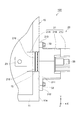
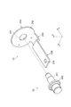
次に、端子台20の端子部材23及び接続部材25について図5及び図6を用いて説明する。図5は、端子部材23及び接続部材25の構成を説明する概略斜視図であり、図6は、端子部材23及び接続部材25を樹脂部21により固定した端子台20の断面図である。
Next, the
端子部材23は、図5に示すように、筺体10に対する端子台20の挿入方向であるX軸方向に沿って延び、一方の端部であって筺体10の外部に露出して外部機器からのケーブル等を介した外部端子が取り付けられる外端部23A(第1の端子)、外端部23Aとは逆側の端部であり筺体10の内部の部品とバスバー(導電部材)等を介して電気的に接続される内端部23B(第2の端子)、及び、外端部23Aと内端部23Bとを接続する折り曲げ部23Cを含んで構成される。外端部23Aは、内側に開口231を有し、YZ平面に沿って延びるドーナツ型の平板状の部材により形成される。また、内端部23Bは、内側にXY平面に沿って延びる平板状の部材により形成され、その端部には、内部の電子部品と接続するためのバスバー等を固定するための開口235が設けられている。この開口235は、内部の電子部品と接続できればよいことから、雄ねじや雌ねじ等でも代替可能である。
As shown in FIG. 5, the
端子部材23は、一枚の平板状の導電材料を切り出して加工することにより作成することができ、折り曲げ部23Cは、YZ平面に対して平行な外端部23Aと、XY平面に対して平行にX軸方向に沿って延びる内端部23Bとを接続するために折り曲げられた領域であり、XY平面に平行な内端部23Bから見て、略垂直方向に下方に折り曲げられた後に、再度略水平方向に折り曲げられ、さらに、略垂直方向に上方に折り曲げられて、YZ平面に平行な外端部23Aとなる。外端部23Aのうち、内端部23B側の面232は接続部材25と当接し、面232の裏側となる面233は、外部に露出し、外部の機器と電気的に接続される面となる。
The
接続部材25は、X軸方向に沿って延びる略円柱状の鉄系の部材からなる本体部251と、本体部251のX軸方向に沿った中ほどから外方へ一様に延びる略円形のフランジ252とを備える。接続部材25は、本体部251が、端子部材23の外端部23Aに設けられた開口231に対して、内端部23B側から挿通される。フランジ252が外端部23Aの面232と当接した状態で端子部材23と接続部材25とを保持し、樹脂部21によって覆い、この樹脂部21が硬化することで端子部材23と接続部材25とが固定される。なお、接続部材25の本体部251は、鉄系の部材からなる構成について説明したが、所望の機械的強度があればよく、例えば樹脂等の絶縁部材で構成しても構わない。
The connecting
図1に戻り、樹脂部21の接続壁部21Cは、端子部材23の外端部23Aの面233を露出した状態で、接続部材25の外端部23A側の端部を取り囲むように形成される。接続壁部21Cの形状は、外端部23Aと接続する外部機器のコネクタの形状等に応じて変更される。本実施形態に係る端子台20の場合、接続部材25と接続壁部21Cとの間に外部機器のコネクタが取り付けられ、コネクタに含まれる導電性の端子と、端子部材23の外端部23Aの面233とが当接することにより、外部機器との間で電気的な接続が行われる。
Returning to FIG. 1, the connecting
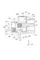
ここで、本実施形態に係る端子台20の技術的特徴の一つをなす部分である挿入部21A側の形状について、図4,図6,図7を主に用いて説明する。図7は、端子台20に係る挿入部21A側からの概略斜視図である。
Here, the shape of the
端子台20の樹脂部21のうち、挿入部21Aは、図6に示すように、挿入部21Aの外形を形成する略円筒状の周縁部271の内側において周縁部271とは離間した位置で端子部材23の内端部23Bが露出している。また、挿入部21Aの周縁部271の内側は、隔壁273が設けられる。これにより、挿入部21Aの内部は、隔壁273と周縁部271とによって囲まれると共に内側の底面A11から端子部材23の内端部23Bが露出した凹形状を有する第1の領域A1と、第1の領域A1とは異なり隔壁273と周縁部271とによって囲まれた凹形状を有する第2の領域A2とに区画される。第1の領域A1及び第2の領域A2の内端部23B側の端部は開放されて、接続壁部21C側の本体部21Bの端部が閉じた凹部形状をなしている。
Of the
第2の領域A2の底面A21には、接続部材25の挿入部21A側の端面253と連通する貫通孔A22が形成される。この貫通孔A22は、図6に示す端子部材23及び接続部材25の配置を保ったまま樹脂部21の樹脂を固化させるために、端子部材23の面232に対して接続部材25のフランジ252を当接させるために用いられる。すなわち、端子部材23及び接続部材25を図6に示す状態で固定するために、貫通孔A22が用いられる。
A through hole A22 communicating with the
上記の構成を有する端子台20においては、筺体10の外部(端子部材23の外端部23A側)に対する内部(端子部材の23の内端部23B側)の気密性を高めることが求められている。本実施形態に係る端子台20においては、外部からのリークが考えられるのは、端子部材23及び接続部材25と、樹脂部21との境界面である。具体的には、図6に示す接続部材25の周囲であって端子部材23の開口231から、接続部材25の貫通孔A22に至るルートと、端子部材23の開口231から端子部材23と樹脂部21の境界を伝って第1の領域A1に至るルートと、端子部材23の面233から端子部材23を伝って第1の領域A1に至るルートにおいてリークが発生する可能性が考えられる。
In the
そこで、周縁部271及び隔壁273によって囲まれた第1の領域A1及び第2の領域A2のそれぞれに対して、樹脂部21とは異なる充填樹脂29A,29Bによってそれぞれ充填されることでこれらの領域は個別に封止される。これにより、上述のリークが発生する可能性が考えられるルートに沿ってリークが発生したとしても充填樹脂29A,29Bにより封止がなされる。これにより、端子部材23及び接続部材25と、樹脂部21との境界面に沿って端子台20の外側と内側との間でリークが発生することを防止することができる。なお、充填樹脂としては、エポキシ系樹脂材が好適に用いられる。
Therefore, each of the first region A1 and the second region A2 surrounded by the
また、第1の領域A1の底面A11上で端子部材23が樹脂部21から露出する領域においては、樹脂部21と端子部材23との剥離を防止するために、傾斜が付けられて樹脂が盛られている肉盛り部275が形成されている。また、肉盛り部275のX軸方向に沿った底面A11からの高さは、周縁部271の底面A11からの高さよりも低い。これにより、第1の領域A1内を充填樹脂29Aによって満たした場合に、肉盛り部275が充填樹脂29Aの表面に露出することが防止される。
Further, in the region where the
本実施形態に係る電子機器100の端子台20では、第1の領域A1と第2の領域A2とが隔壁273によって区画されていることによって、第1の領域A1の底面A11と、第2の領域A2の底面A21の位置が、端子部材23の延在方向(X軸方向)に沿って互いに異なる構成とすることができる。これにより、第1の領域A1及び第2の領域A2における充填樹脂の充填量をそれぞれ好適に調整することができる。例えば、端子台20では、図6に示すように、端子部材23の外端部23A側に接続部材25が突出する構成となっているので、内端部23B側の接続部材25の端面253は、端子部材23の内端部23BとX軸方向における位置が大きく異なる。
In the
ここで、第1の領域A1と第2の領域A2とが隔壁273によって区画されておらず1つの凹型部として形成されている場合、充填樹脂によって、接続部材25の端面253と連通する貫通孔A22を塞ぎつつ且つ端子部材23と樹脂部21との境界部(肉盛り部275が形成されている部分)を塞ぐ必要があることから、充填樹脂を相当量準備する必要がある。気密性を高めるために用いられる充填樹脂は高価であり、使用量の増加は端子台製造のコストに直結する。
Here, when 1st area | region A1 and 2nd area | region A2 are not divided by the
これに対して、本実施形態に係る電子機器100の端子台20では、隔壁273によって第1の領域A1と第2の領域A2とを区切ることで、貫通孔A22を塞ぐために必要な充填樹脂29Aと、端子部材23と樹脂部21との境界部を塞ぐための充填樹脂29Bとを個別に充填することができる。したがって、充填樹脂29A,29Bの充填量をそれぞれ調整することができるため、気密性を高めるために必要な充填樹脂を適切に充填することができると共に、封止のための充填樹脂の使用量を低減することが可能となる。
On the other hand, in the
また、本実施形態に係る電子機器100の端子台20では、外端部23Aと内端部23Bとの間に折り曲げ部23が設けられていることにより、外端部23Aと内端部23Bとの間の端子部材23の形状が直線ではなく曲げられて形成されている。これにより、端子部材23と樹脂部21の境界面に沿ってリークが発生することを防止することができ、端子台20における気密性を高めることができる。
Further, in the
以上、本発明の実施形態について説明したが、本発明に係る電子機器100は種々の変更を行うことができる。例えば、上記実施形態では、端子部材23の外端部23Aが略垂直方向に延びる面に折り曲げられている場合について説明したが、外端部23Aの延びる方向は垂直方向でなくてもよい。同様に、端子部材23、接続部材25の形状は適宜変更することができる。例えば、端子部材23が折り曲げ部23Cを備える構成について説明したが、端子部材23が折り曲げ部23Cを備えない構成であってもよい。また、端子部材23が平板状の部材によって構成されていなくてもよい。また、端子部材23の折り曲げ部23Cは、斜め状に形成されていても良い。また、接続部材25は、雄ねじではなく雌ねじでも良い。
As mentioned above, although embodiment of this invention was described, the
また、上記実施形態では、端子台20の端子部材23は、筺体10内部を流れる電流を外部の他の装置・機器に対して出力する機能を有する場合について説明したが、外部からの電流を筺体10の内部の部品に対して入力する入力端子として機能する構成であってもよい。この場合であっても、外部に対する気密性の向上は要求されるので、上記実施形態で示した構造を有することにより、気密性の向上と封止のための樹脂の使用量の低減とを達成することができる。
Moreover, in the said embodiment, although the
また、上記実施形態では、電子機器100に含まれる筺体10等の構成については適宜変更することができる。また、筺体10には内部の電子部品等を冷却するための冷却手段を備えていてもよい。
Moreover, in the said embodiment, about the structure of the
また、電子機器100は、スイッチング電源装置に限定されない。すなわち、本実施形態に係る電子機器100は、その内部と外部の他の電子機器とが電気的に接続される端子台20が用いられる構成であれば特に限定されない。
Moreover, the
10…筺体、11…側壁、20…端子台、21…樹脂部、21A…挿入部、21B…本体部、21C…接続壁部、23…端子部材、25…接続部材、29A,29B…充填樹脂、32,33…ネジ、100…電子機器。
DESCRIPTION OF
ここで、前記樹脂部のうち、前記第1の領域の底面における前記端子部材との境界部には肉盛り部が設けられ、前記端子部材の延在方向に沿った前記肉盛り部の高さは、前記側壁の高さよりも低い態様とすることができる。
Here, in the resin portion, a build-up portion is provided at a boundary portion between the bottom surface of the first region and the terminal member, and the height of the build-up portion along the extending direction of the terminal member. May be lower than the height of the side wall.
Claims (6)
本体部の中ほどから外方に伸びるフランジを備え、前記端子部材における前記第1の端子の前記開口に対して前記第2の端子側から挿通されて、前記フランジが前記第1の端子に対して当接した状態で固定される接続部材と、
前記第1の端子側で前記第1の端子と前記接続部材の少なくとも一部とが露出し、前記第2の端子側で前記第2の端子が露出した状態で、前記端子部材及び前記接続部材の周囲を覆う樹脂部と、
を備え、
前記樹脂部は、前記第2の端子側の端部において前記端子部材の延在方向に沿って前記第2の端子側に延びて、前記端子部材を取り囲むように形成された筒状の側壁と、前記側壁に囲まれた領域を第1の領域と第2の領域とに区画する隔壁と、を有し、
前記第1の領域の底面から前記端子部材が突出すると共に、
前記第2の領域の底面には、前記接続部材の前記第2の端子側の端面と連通する貫通孔が設けられる
ことを特徴とする端子台。 A terminal member in which a first terminal having an opening on one end side is formed and a second terminal is formed on the other end side different from the one end side;
A flange extending outward from the middle of the main body, and inserted from the second terminal side with respect to the opening of the first terminal in the terminal member, and the flange with respect to the first terminal; And a connecting member fixed in a contact state,
The terminal member and the connection member in a state where the first terminal and at least a part of the connection member are exposed on the first terminal side and the second terminal is exposed on the second terminal side A resin part covering the periphery of
With
The resin portion extends to the second terminal side along the extending direction of the terminal member at the end portion on the second terminal side, and has a cylindrical side wall formed so as to surround the terminal member. A partition wall that partitions the region surrounded by the side wall into a first region and a second region,
The terminal member protrudes from the bottom surface of the first region,
A terminal block, wherein a through hole communicating with an end face of the connection member on the second terminal side is provided on a bottom surface of the second region.
前記端子部材の延在方向に沿った前記面取り加工部の高さは、前記側壁の高さよりも低いことを特徴とする請求項1記載の端子台。 Of the resin portion, a built-up portion is provided at a boundary portion with the terminal member at the bottom surface of the first region,
The terminal block according to claim 1, wherein a height of the chamfered portion along the extending direction of the terminal member is lower than a height of the side wall.
前記第1の端子と前記第2の端子との間は、折り曲げ部が形成されていることを特徴とする請求項1〜4のいずれか一項に記載の端子台。 The terminal member is
The terminal block according to claim 1, wherein a bent portion is formed between the first terminal and the second terminal.
前記端子台を取り付けるための取付け部を備え、前記端子台と電気的に接続された電子部品が内部に収容された筺体と、
前記取付け部において前記端子台と前記筺体との間隙を塞ぐシール材と、
を備える電子機器。
The terminal block according to any one of 1 to 5;
A housing that includes an attachment part for attaching the terminal block, and in which an electronic component electrically connected to the terminal block is housed,
A sealing material that closes a gap between the terminal block and the housing in the attachment portion;
Electronic equipment comprising.
Priority Applications (3)
| Application Number | Priority Date | Filing Date | Title |
|---|---|---|---|
| JP2013033418A JP5660148B2 (en) | 2013-02-22 | 2013-02-22 | Terminal block and electronic device including the same |
| US14/162,295 US9071005B2 (en) | 2013-02-22 | 2014-01-23 | Terminal block and electronic device comprising same |
| CN201410061686.5A CN104009323B (en) | 2013-02-22 | 2014-02-24 | Terminal board and comprise its electronic equipment |
Applications Claiming Priority (1)
| Application Number | Priority Date | Filing Date | Title |
|---|---|---|---|
| JP2013033418A JP5660148B2 (en) | 2013-02-22 | 2013-02-22 | Terminal block and electronic device including the same |
Publications (2)
| Publication Number | Publication Date |
|---|---|
| JP2014164875A true JP2014164875A (en) | 2014-09-08 |
| JP5660148B2 JP5660148B2 (en) | 2015-01-28 |
Family
ID=51369884
Family Applications (1)
| Application Number | Title | Priority Date | Filing Date |
|---|---|---|---|
| JP2013033418A Active JP5660148B2 (en) | 2013-02-22 | 2013-02-22 | Terminal block and electronic device including the same |
Country Status (3)
| Country | Link |
|---|---|
| US (1) | US9071005B2 (en) |
| JP (1) | JP5660148B2 (en) |
| CN (1) | CN104009323B (en) |
Cited By (2)
| Publication number | Priority date | Publication date | Assignee | Title |
|---|---|---|---|---|
| KR101851626B1 (en) * | 2016-10-26 | 2018-04-25 | 주식회사 현대포리텍 | terminal connector |
| US10952343B2 (en) | 2017-11-16 | 2021-03-16 | Tokai Kogyo Co., Ltd. | Assembled body |
Families Citing this family (7)
| Publication number | Priority date | Publication date | Assignee | Title |
|---|---|---|---|---|
| JP1524733S (en) * | 2014-12-12 | 2015-06-01 | ||
| DE102017207215A1 (en) * | 2017-04-28 | 2018-10-31 | Zf Friedrichshafen Ag | connecting device |
| CN107196159A (en) * | 2017-06-21 | 2017-09-22 | 赛尔富电子有限公司 | A kind of shelf electricity getting system |
| JP2019012590A (en) * | 2017-06-29 | 2019-01-24 | Tdk株式会社 | Terminal block and electronic device |
| CA3025157C (en) * | 2017-11-29 | 2024-04-02 | Submariner Electric Motor LLC | Terminal block and stud for transitionning an electrical connection between two distinct areas |
| JP7122674B2 (en) * | 2018-09-27 | 2022-08-22 | パナソニックIpマネジメント株式会社 | Electrical equipment and electromagnetic relays |
| US11888257B2 (en) * | 2021-05-13 | 2024-01-30 | Schaeffler Technologies AG & Co. KG | High voltage connection for busbar assembly |
Citations (5)
| Publication number | Priority date | Publication date | Assignee | Title |
|---|---|---|---|---|
| JPH023673U (en) * | 1988-06-21 | 1990-01-11 | ||
| JPH09147968A (en) * | 1995-11-21 | 1997-06-06 | Sumitomo Wiring Syst Ltd | Seal structure of terminal metal fitting |
| JPH10116646A (en) * | 1996-10-11 | 1998-05-06 | Sumitomo Wiring Syst Ltd | Connector |
| JP2002305065A (en) * | 2001-04-04 | 2002-10-18 | Nippon Mektron Ltd | Sealing method between connector terminal insertion opening and electric wire, and waterproofing connector |
| JP2012134130A (en) * | 2010-12-02 | 2012-07-12 | Jst Mfg Co Ltd | Waterproof connector, and method of manufacturing the same |
Family Cites Families (8)
| Publication number | Priority date | Publication date | Assignee | Title |
|---|---|---|---|---|
| JP3110494B2 (en) | 1991-06-14 | 2000-11-20 | バーグ・テクノロジー・インコーポレーテッド | connector |
| JPH0737049A (en) * | 1993-07-23 | 1995-02-07 | Toshiba Corp | External storage |
| US7300292B2 (en) * | 2001-07-13 | 2007-11-27 | Hosiden Corporation | Jack type connector with a shutter, and plug type connector |
| JP2007073449A (en) | 2005-09-09 | 2007-03-22 | Denso Corp | Connector case |
| JP5147206B2 (en) * | 2006-08-11 | 2013-02-20 | 三洋電機株式会社 | Nonaqueous electrolyte secondary battery |
| JP4797892B2 (en) * | 2006-09-07 | 2011-10-19 | 住友電装株式会社 | Shield connector |
| JP4680231B2 (en) * | 2007-04-18 | 2011-05-11 | トヨタ自動車株式会社 | connector |
| DE102010031771B4 (en) * | 2009-08-10 | 2014-07-03 | Sumitomo Wiring Systems, Ltd. | Connector manufacturing method, mold |
-
2013
- 2013-02-22 JP JP2013033418A patent/JP5660148B2/en active Active
-
2014
- 2014-01-23 US US14/162,295 patent/US9071005B2/en active Active
- 2014-02-24 CN CN201410061686.5A patent/CN104009323B/en active Active
Patent Citations (5)
| Publication number | Priority date | Publication date | Assignee | Title |
|---|---|---|---|---|
| JPH023673U (en) * | 1988-06-21 | 1990-01-11 | ||
| JPH09147968A (en) * | 1995-11-21 | 1997-06-06 | Sumitomo Wiring Syst Ltd | Seal structure of terminal metal fitting |
| JPH10116646A (en) * | 1996-10-11 | 1998-05-06 | Sumitomo Wiring Syst Ltd | Connector |
| JP2002305065A (en) * | 2001-04-04 | 2002-10-18 | Nippon Mektron Ltd | Sealing method between connector terminal insertion opening and electric wire, and waterproofing connector |
| JP2012134130A (en) * | 2010-12-02 | 2012-07-12 | Jst Mfg Co Ltd | Waterproof connector, and method of manufacturing the same |
Cited By (2)
| Publication number | Priority date | Publication date | Assignee | Title |
|---|---|---|---|---|
| KR101851626B1 (en) * | 2016-10-26 | 2018-04-25 | 주식회사 현대포리텍 | terminal connector |
| US10952343B2 (en) | 2017-11-16 | 2021-03-16 | Tokai Kogyo Co., Ltd. | Assembled body |
Also Published As
| Publication number | Publication date |
|---|---|
| US9071005B2 (en) | 2015-06-30 |
| CN104009323B (en) | 2016-05-04 |
| JP5660148B2 (en) | 2015-01-28 |
| CN104009323A (en) | 2014-08-27 |
| US20140242838A1 (en) | 2014-08-28 |
Similar Documents
| Publication | Publication Date | Title |
|---|---|---|
| JP5660148B2 (en) | Terminal block and electronic device including the same | |
| EP3246601B1 (en) | Electronic control device | |
| CN102544844A (en) | Partially encapsulated power-supply unit and method of producing the same | |
| CN102754533B (en) | For the device of shielding electronic module | |
| US10609831B2 (en) | Circuit unit, electrical junction box, and production method of circuit unit | |
| CN103178320A (en) | Feed through emc filter | |
| JP2019012590A (en) | Terminal block and electronic device | |
| KR101982542B1 (en) | Waterproof case, power supply, and assembly method | |
| CN102220963A (en) | Electronic control unit | |
| JP2018116896A (en) | connector | |
| US10931060B2 (en) | Connector with an annular shaped magnetic core and an insulating potting agent | |
| JP2017069317A (en) | Noise reduction device | |
| US20230163693A1 (en) | Power conversion device | |
| CN110324998A (en) | A kind of shell and electronic equipment | |
| KR20180118768A (en) | controller | |
| JP2017046396A (en) | Electric junction box | |
| US9397436B2 (en) | Electrical coupling device for a machine | |
| JP2016059242A (en) | Power conversion device | |
| JP7432617B2 (en) | Power converters and motors | |
| WO2019131005A1 (en) | Electrical circuit device | |
| JP2011133452A (en) | Instrument casing | |
| CN108886242B (en) | Electric connection structure | |
| JP2014010994A (en) | Connector forming method | |
| JP5384817B2 (en) | Electrical junction box | |
| JP2014010995A (en) | Connector forming method |
Legal Events
| Date | Code | Title | Description |
|---|---|---|---|
| A131 | Notification of reasons for refusal |
Free format text: JAPANESE INTERMEDIATE CODE: A131 Effective date: 20140819 |
|
| A521 | Written amendment |
Free format text: JAPANESE INTERMEDIATE CODE: A523 Effective date: 20141014 |
|
| TRDD | Decision of grant or rejection written | ||
| A01 | Written decision to grant a patent or to grant a registration (utility model) |
Free format text: JAPANESE INTERMEDIATE CODE: A01 Effective date: 20141104 |
|
| A61 | First payment of annual fees (during grant procedure) |
Free format text: JAPANESE INTERMEDIATE CODE: A61 Effective date: 20141117 |
|
| R150 | Certificate of patent or registration of utility model |
Ref document number: 5660148 Country of ref document: JP Free format text: JAPANESE INTERMEDIATE CODE: R150 |