JP2014163521A - Vaporizer - Google Patents
Vaporizer Download PDFInfo
- Publication number
- JP2014163521A JP2014163521A JP2013031693A JP2013031693A JP2014163521A JP 2014163521 A JP2014163521 A JP 2014163521A JP 2013031693 A JP2013031693 A JP 2013031693A JP 2013031693 A JP2013031693 A JP 2013031693A JP 2014163521 A JP2014163521 A JP 2014163521A
- Authority
- JP
- Japan
- Prior art keywords
- heater
- vaporization
- heat
- vaporizer
- unit
- Prior art date
- Legal status (The legal status is an assumption and is not a legal conclusion. Google has not performed a legal analysis and makes no representation as to the accuracy of the status listed.)
- Granted
Links
Images


Abstract
Description
本発明は、灯油等の液体燃料を加熱気化して気化ガスを生成する気化装置に関するものである。 The present invention relates to a vaporizer that heats and vaporizes liquid fuel such as kerosene to generate vaporized gas.
従来、この種の気化装置として特許文献1に示すようなものがある。特許文献1の気化装置は液体燃料を加熱気化する筒状の気化部と、この気化部と連通し交差配設され気化部で加熱気化された気化ガスを先端部の噴出口より噴出するノズル部とから構成されている。
Conventionally, there exists a thing as shown to patent
そして気化部は、筒状の発熱体の内側に基端部から前記液体燃料が供給される内管を設けてこれを前段気化室とし、この筒状の発熱体を収納管に収納し、この収納管の外側に気化ガス通路となる間隙を介して更に内管と先端部で連通する外管を設けてこの外管の内側即ちこの外管と収納管との間を前段気化室と折り返し連通する後段気化室とし、この後段気化室の下流側に前記ノズル部と連通する連通口を設けた構成としている。 The vaporizing section is provided with an inner tube to which the liquid fuel is supplied from the base end portion inside the cylindrical heating element, which is used as a pre-stage vaporizing chamber, and the cylindrical heating element is stored in the storage tube. An outer tube that communicates with the inner tube and the tip through a gap serving as a vaporized gas passage is provided outside the storage tube, and the inner stage of the outer tube, that is, between the outer tube and the storage tube, communicates with the previous vaporization chamber. The rear vaporization chamber is configured such that a communication port communicating with the nozzle portion is provided on the downstream side of the rear vaporization chamber.
このように、従来の気化装置は構造が複雑でかつ部品点数も多いため、溶接や組立の手間がかかるものであった。また、この種の気化装置は、搭載される燃焼装置の燃焼量に応じて気化能力の異なるタイプが必要とされるが、気化能力の異なる気化装置を製造するためには、それぞれのタイプごとに長さや大きさの異なる部品、またそれを成形するための金型が必要になってしまうため、製造コストを低減することが難しかった。 As described above, the conventional vaporizer has a complicated structure and a large number of parts, so that it takes time and effort for welding and assembly. In addition, this type of vaporizer requires different types of vaporization capability depending on the amount of combustion of the installed combustion device. In order to manufacture vaporizers with different vaporization capabilities, Since parts with different lengths and sizes and a mold for molding the parts are required, it is difficult to reduce the manufacturing cost.
本発明は、構造が簡単で溶接などの手間が少なく、さらに気化能力の異なるタイプも簡単に製造することのできる気化装置を提供することを目的とする。 An object of the present invention is to provide a vaporizer that has a simple structure, requires less labor such as welding, and can easily manufacture types having different vaporization capabilities.
本発明は、火炎から燃焼熱を回収する熱回収部と、ヒータが取り付けられてヒータからの熱を受けるヒータ受熱部と、液体燃料を気化して気化ガスとする気化容器とからなり、液体燃料を加熱して気化ガスとする気化部を備えた気化装置であって、前記熱回収部とヒータ受熱部とを押出加工により一体形成したことを特徴とする気化装置である。 The present invention includes a heat recovery unit that recovers combustion heat from a flame, a heater heat receiving unit to which a heater is attached and receives heat from the heater, and a vaporization container that vaporizes liquid fuel to form a vaporized gas. It is a vaporization apparatus provided with the vaporization part which heats and makes vaporized gas, Comprising: The said heat recovery part and the heater heat receiving part were integrally formed by the extrusion process.
また、前記熱回収部とヒータ受熱部の押出方向が気化部の幅方向であることを特徴とする請求項1記載の気化装置である。
2. The vaporizer according to
また、前記気化容器は上面が開口し、この開口端面と前記ヒータ受熱部とを接合して気化部が構成されることを特徴とする請求項2記載の気化装置である。
The vaporization apparatus according to
また、前記ヒータは平板状セラミックヒータであり、前記ヒータ受熱部には前記ヒータを設置する平面であるヒータ設置面が形成されていることを特徴とする請求項3記載の気化装置である。
4. The vaporizer according to
また、前記ヒータと前記ヒータ設置面との間に伝熱シートを介在させたことを特徴とする請求項4記載の気化装置である。
The vaporizer according to
また前記ヒータ設置面には、押出方向に沿って一対のヒータ係止部が突出形成され、このヒータ係止部の間に前記ヒータを配置するとともにヒータ押さえ金具を係止させて前記ヒータを固定することを特徴とする請求項4または5記載の気化装置である。
In addition, a pair of heater locking portions project from the heater installation surface along the extrusion direction, and the heater is fixed between the heater locking portions and the heater pressing metal fittings that are disposed between the heater locking portions. 6. The vaporizer according to
上述のように構成することにより、部品点数を削減して溶接などの手間を減らすことができるとともに、気化能力の異なる気化装置に対応する部品を押出長を変えるだけで簡単に製造することが可能となる。 By configuring as described above, it is possible to reduce the number of parts and reduce the labor of welding and the like, and it is possible to easily manufacture parts corresponding to vaporizers with different vaporization capabilities by simply changing the extrusion length. It becomes.
好適と考える本発明の実施形態を、本発明の作用効果を示して簡単に説明する。 Embodiments of the present invention that are considered to be suitable will be briefly described by showing the effects of the present invention.
本発明の気化装置は、熱回収部とヒータ受熱部を押出加工により一体成形することにより、部品点数を減らし溶接や組立の手間を削減することができる。さらに、成形には押出加工を用いたので、押出長を変えるだけで異なる気化能力の気化装置に対応する部品を製造することができるため、金型の共有による製造コストの低減を図ることができる。 The vaporization apparatus of the present invention can reduce the number of parts and labor of welding and assembly by integrally forming the heat recovery part and the heater heat receiving part by extrusion. Furthermore, since extrusion is used for molding, parts corresponding to vaporizers with different vaporization capacities can be manufactured simply by changing the extrusion length, so that the manufacturing cost can be reduced by sharing the mold. .
また、熱回収部とヒータ受熱部の幅方向を押出方向とすることで、押出長を変えることにより火炎からの熱回収量とヒータ受熱量を増減することができるため、気化能力の調整を容易に行うことができる。 Also, by adjusting the width of the heat recovery section and the heater heat receiving section to the extrusion direction, the amount of heat recovered from the flame and the amount of heat received by the heater can be increased or decreased by changing the extrusion length, making it easy to adjust the vaporization capacity Can be done.
また、気化容器はプレス加工による成形が可能な形状であり、この気化容器とヒータ受熱部とを接合することにより簡単に気化部を構成することができる。 The vaporization container has a shape that can be molded by press working, and the vaporization section can be easily configured by joining the vaporization container and the heater heat receiving section.
また、セラミックヒータはワット密度が高く熱容量が小さいため熱効率がよく、さらに平板状とすることでヒータ設置面との接触面積が増えるので、気化装置を素早く昇温させることができる。なお、ヒータ設置面が歪んでいたり細かい凹凸があったりすると、ヒータとの間に隙間ができて加熱効率が低下したり、取り付けの際にヒータが破損してしまうおそれがあるが、押出加工で成形された表面は非常に滑らかであるため、仕上げ加工を施さなくてもヒータとヒータ設置面とを密着させることができる。 In addition, since the ceramic heater has a high watt density and a small heat capacity, it has good thermal efficiency. Further, since the contact area with the heater installation surface is increased by using a flat plate shape, the vaporizer can be quickly heated. If the heater installation surface is distorted or has fine irregularities, a gap may be formed between the heater and heating efficiency may be reduced, or the heater may be damaged during installation. Since the molded surface is very smooth, the heater and the heater installation surface can be brought into close contact with each other without finishing.
また、気化装置の製造工程においてヒータ設置面に異物が付着してしまうと、ヒータ設置面が滑らかであってもヒータとヒータ設置面の間に隙間ができて加熱効率が低下してしまうが、伝熱シートを介在させることで隙間を防止することができる。 In addition, if foreign matter adheres to the heater installation surface in the manufacturing process of the vaporizer, even if the heater installation surface is smooth, there is a gap between the heater and the heater installation surface, which reduces the heating efficiency. A gap can be prevented by interposing a heat transfer sheet.
また、ヒータ設置面に形成した一対のヒータ係止部とヒータ押さえ金具によりヒータを固定するため、確実にヒータ設置面とヒータとを密着させることができる。さらに、このヒータ係止部は押出方向に沿って設けられているため、押出加工の際に形成することができ加工の手間もかからない。 In addition, since the heater is fixed by the pair of heater locking portions and the heater pressing metal formed on the heater installation surface, the heater installation surface and the heater can be securely adhered to each other. Furthermore, since this heater latching | locking part is provided along the extrusion direction, it can be formed in the case of an extrusion process, and does not require the effort of a process.
以下本発明の一実施例としての液体燃料燃焼装置を図面により説明する。 Hereinafter, a liquid fuel combustion apparatus as an embodiment of the present invention will be described with reference to the drawings.
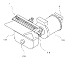
図1は気化装置の外観図、図2は気化装置の断面図である。気化装置1は、液体燃料を気化して気化ガスとする気化部10と、気化部10で生成された気化ガスを噴出するノズル部20と、ノズル部20を開閉させるプランジャー部30とから構成されている。
FIG. 1 is an external view of the vaporizer, and FIG. 2 is a cross-sectional view of the vaporizer. The
気化部10は、図示しないバーナで形成される火炎の燃焼熱を回収する熱回収部11と、通電することで発熱するヒータ12と、ヒータ12と密着するヒータ設置面131が形成されてヒータ12が発する熱を受けるヒータ受熱部13と、液体燃料が供給される気化容器14を備えている。そして、ヒータ12とヒータ設置面131の間には伝熱シート15が挟みこまれ、ヒータ押さえ金具121によりヒータ12がヒータ設置面131に密着固定されている。
The
このように気化装置1が熱回収部11を備えることにより、燃焼開始時にはヒータ12が発する熱により気化装置1を加熱し、燃焼が開始してバーナで火炎が形成された後は熱回収部11が回収した燃焼熱により気化装置1が加熱される。気化装置1が加熱されることで気化容器14が高温となり、気化容器14に供給された液体燃料は加熱されて気化し気化ガスとなる。
Since the
そして、熱回収部11と、ヒータ受熱部13は押出加工により一体に成形されて気化ヘッド16を構成している。図3は気化ヘッド16を示す図であって、以下の説明においては、気化ヘッド16の横幅を「幅方向X」、鉛直方向を「高さ方向Y」、ノズル部20が気化部10を貫通する方向を「奥行き方向Z」として説明を行う。
The
気化ヘッド16は、幅方向Xの断面(Y−Z断面)が全ての点において同一の形状をなしている。このような形状とすることで、気化ヘッド16の幅方向Xを押出方向として金型から押し出すことで気化ヘッド16が成形されるため、従来の構造と比べて溶接の手間を大幅に低減することができる。なお、本実施例においては、気化ヘッド16は全ての点におけるY−Z断面が同一形状であるが、押出加工後に抜き加工や曲げ加工を行うことにより断面形状が異なるようにしてもよい。また、押出加工後に寸法精度向上等のために、引抜加工を行うことも可能である。
The vaporizing
この種の気化装置1は、搭載される燃焼装置の燃焼量に応じて気化能力の異なるタイプが必要とされる。気化能力は気化容器14の容積、ヒータ12からの受熱量、熱回収量を調整することで変更されるため、従来は気化能力の異なる気化装置1を製造するためには長さや大きさの異なる部品、またそれを成形するための金型がタイプごとに必要になってしまっていた。ところが、本発明の気化装置1は、ヒータ12の受熱量および熱回収量に関しては、気化ヘッド16の幅方向Xの長さを変えることによって増減させて気化能力を変更することができ、さらにそれを押出加工の押出長により調整することができるため、1つの押出金型で気化能力の異なる気化装置1の気化ヘッド16を製造することができる。つまり、気化ヘッド16を押出加工で一体に成形することで、溶接工程の低減だけでなく、金型の共通化も可能となるため、従来と比べて大幅に気化装置の製造能力を向上させることができる。
This type of
また、気化容器14は上面が開口した略箱型形状の容器であり、この開口端面を気化ヘッド16のヒータ受熱部13の底部に接合して気化部10が構成される。その際、気化ヘッド16の底面に形成された張出部161が気化容器14に嵌合するため、位置ズレをおこすことがなく接合作業を容易に行うことができる。
Further, the
つまり、気化容器14もプレス加工により成形が可能であり溶接の手間はかからない。気化部10は気化ヘッド16と気化容器14を接合することにより構成されるため、従来に比べて少ない工程で製造することが可能となる。
That is, the
ヒータ12は、アルミナや窒化ケイ素などの材料からなる平板状のセラミックヒータを用いている。セラミックヒータは、ワット密度が高く熱容量が小さいため熱効率がよく、また形状を平板状とすることでヒータ設置面131との接触面積が増えるので、気化装置1を素早く昇温させることができる。
As the
ヒータ設置面131からは、気化ヘッド16の押出方向(幅方向X)に沿って一対のヒータ係止部132が突出形成されている。このヒータ係止部132は、ヒータ設置面131から立ち上がる突出部133と、突出部133の先端に設けられたフランジ部134からなり、気化ヘッド16の押出加工時に同時に形成されるものである。そして、突出部133の間にヒータ12を嵌め込むことでヒータ12が位置決めされて、さらにフランジ部134にヒータ押さえ金具121を引っ掛けて固定することで、ヒータ12がヒータ設置面131に押し付けられて固定される。
From the
ところで、ヒータ設置面131が歪んでいたり細かい凹凸があったりすると、ヒータ12とヒータ設置面131の間に隙間ができてしまい加熱効率が低下してしまう。特にセラミックヒータはそれ自身に柔軟性がないため、歪みや凹凸の程度によっては取り付けの際にヒータ12が破損してしまうおそれがあり、歪みや凹凸がある場合には仕上げ加工を行い表面を滑らかにしなくてはならない。しかし、押出加工で成形された表面は非常に滑らかであるため、ヒータ設置面131には仕上げ加工を施さなくてもヒータ12とヒータ設置面131とを密着させることができる。
By the way, if the
また、気化装置1の製造工程においてヒータ設置面131に異物が付着すると、ヒータ設置面131が滑らかであってもヒータ12とヒータ設置面131の間に隙間ができて加熱効率が低下してしまう。そこで、ヒータ12とヒータ設置面131との間に伝熱シート15を挟み込むことで、異物が付着した際の隙間を防止している。伝熱シート15の素材としては様々なものがあるが、熱伝導性が高く柔軟性のあるグラファイト系の伝熱シートが好ましい。
Further, if foreign matter adheres to the
気化容器14には送油パイプ4と接続された燃料吐出口18が取付けられていて、この送油パイプ4は電磁ポンプ3を介して油受皿2に繋がっており、電磁ポンプ3を駆動することで送油パイプ4を通して油受皿2に貯められた液体燃料が気化容器14に供給される。そして、気化容器14の前面と背面にはノズル部20が貫通する貫通孔143、144が形成されている。
A
ノズル部20は、気化容器14に設けられた貫通孔143、144を貫通し、後端がプランジャー部30に接続されている筒状のノズルパイプ21から構成されている。このノズルパイプ21の上部には気化容器14内に連通する連通口24が形成されるとともに、先端には噴出口22が設けられており、気化容器14で発生した気化ガスは、連通口24からノズルパイプ21内に流入し、噴出口22よりバーナに向けて噴出される。
The
プランジャー部30は、円筒部311と小径部312が深絞り加工により一体に形成された筒体31と、ソレノイドコイル32を備え、ソレノイドコイル32の内部に筒体31を貫通して構成される。また、この筒体31の円筒部311には、後端に固定された固定片34と、内部を摺動自在な可動片33と、固定片34と可動片33の間に介在するスプリング35が設けられている。ソレノイドコイル32は通電されることで磁気力を発生し、この磁気力により可動片33を吸引する。
The
固定片34には小空間であるニゲ部36が形成され、このニゲ部36を通じて気化容器14やノズルパイプ21内に残留した気化ガスを油受皿2に戻すためのニゲパイプ5が接続されている。
The fixed
可動片33は、内部に固定片34のニゲ部36を閉塞するプランジャー弁37が挿入固定されるとともに、ノズルパイプ21側に向けてバルブロッド38が取り付けられており、このバルブロッド38は先細り形状をなしていてその先端にはノズルパイプ21の噴出口22を開閉する弁針381が形成されている。また、可動片33はスプリング35の付勢力により常時ノズルパイプ21側に押圧されていて、これにより弁針381が噴出口22を閉塞した状態となっている。
In the movable piece 33, a
次に、上述の構成における気化装置の動作について説明する。 Next, the operation of the vaporizer in the above configuration will be described.
燃焼開始が指示されると、ヒータ12への通電が行われ、ヒータ12の発する熱はヒータ受熱部13を介して伝熱され、気化容器14の温度を上昇させる。気化容器14の温度はサーミスタ(図示せず)により検知されており、気化容器14が液体燃料を気化することのできる温度まで上昇すると電磁ポンプ3が始動して油受皿2内の液体燃料を汲み上げ、液体燃料は送油パイプ4を通過して燃料吐出口18から気化容器14内に供給される。気化容器14内に供給された液体燃料は加熱されて気化し、気化ガスとなる。
When the start of combustion is instructed, the
気化容器14で発生した気化ガスは気化容器14内に拡散し、連通口24からノズルパイプ21内に流入する。ノズルパイプ21は気化容器14の熱により高温に維持されるので、ノズルパイプ21に流入した気化ガスの温度を低下させないため、燃焼状態を良好に維持することができる。
The vaporized gas generated in the
そして、電磁ポンプ3の始動に相前後してソレノイドコイル32に通電が行われ、ソレノイドコイル32の磁気力により可動片33が吸引されて固定片34側に摺動する。可動片33が摺動することでバルブロッド38も固定片34側に移動するため、バルブロッド38の先端に設けられた弁針381が噴出口22から離脱し、さらにプランジャー弁37が固定片34のニゲ部36を閉塞するため、ノズルパイプ21内に流入した気化ガスは噴出口22よりバーナに向けて噴出される。
The
バーナで火炎が形成されると、熱回収部11は火炎に晒されて燃焼熱を回収するので、熱回収部11が火炎から回収した燃焼熱は、ヒータ受熱部13を介して気化容器14へ伝熱し、気化容器14を加熱するようになる。
When the flame is formed by the burner, the
気化容器14の温度は常時サーミスタにより検知されており、気化容器14の温度が液体燃料の気化に適した温度となるようヒータ12への通電が制御され、熱回収部11が回収した熱により気化容器14が十分に加熱される状態であれば、ヒータ12への通電を停止する。これにより、燃焼中の消費電力を低減させることができる。
The temperature of the
そして、燃焼停止の指示があると、ヒータ12及び電磁ポンプ3への通電を停止させると同時にソレノイドコイル32への通電を停止する。ソレノイドコイル32への通電が停止されると、可動片33はスプリング35の付勢力によってノズルパイプ21側に摺動して押圧されるので、バルブロッド38も噴出口22側へ移動して先端の弁針381が噴出口22を閉塞するため、気化容器14に残った気化ガスが噴出口22から漏れ出すことが防止される。また同時に、プランジャー弁37によって閉塞されていたニゲ部36が開放されるので、気化容器14やノズルパイプ21内に残留する気化ガスはニゲ部36からニゲパイプ5を通って油受皿2に戻される。
When there is an instruction to stop combustion, the energization to the
1 気化装置
10 気化部
11 熱回収部
12 ヒータ
121 ヒータ押さえ金具
13 ヒータ受熱部
131 ヒータ設置面
132 ヒータ係止部
14 気化容器
15 伝熱シート
DESCRIPTION OF
Claims (6)
Priority Applications (1)
| Application Number | Priority Date | Filing Date | Title |
|---|---|---|---|
| JP2013031693A JP5951521B2 (en) | 2013-02-21 | 2013-02-21 | Vaporizer |
Applications Claiming Priority (1)
| Application Number | Priority Date | Filing Date | Title |
|---|---|---|---|
| JP2013031693A JP5951521B2 (en) | 2013-02-21 | 2013-02-21 | Vaporizer |
Publications (2)
| Publication Number | Publication Date |
|---|---|
| JP2014163521A true JP2014163521A (en) | 2014-09-08 |
| JP5951521B2 JP5951521B2 (en) | 2016-07-13 |
Family
ID=51614304
Family Applications (1)
| Application Number | Title | Priority Date | Filing Date |
|---|---|---|---|
| JP2013031693A Active JP5951521B2 (en) | 2013-02-21 | 2013-02-21 | Vaporizer |
Country Status (1)
| Country | Link |
|---|---|
| JP (1) | JP5951521B2 (en) |
Citations (8)
| Publication number | Priority date | Publication date | Assignee | Title |
|---|---|---|---|---|
| JPS54161129A (en) * | 1978-06-09 | 1979-12-20 | Hitachi Ltd | Linear liquid fuel gasification type combustor |
| JPS5832215U (en) * | 1981-08-24 | 1983-03-02 | 株式会社日立製作所 | Kerosene vaporizing burner |
| JPS58185727U (en) * | 1982-06-04 | 1983-12-09 | シャープ株式会社 | Heater mounting device for liquid fuel vaporization type combustor |
| JPS6314187Y2 (en) * | 1982-05-10 | 1988-04-21 | ||
| JPH0324989Y2 (en) * | 1985-06-18 | 1991-05-30 | ||
| JPH04161707A (en) * | 1990-10-24 | 1992-06-05 | Noritz Corp | Kerosene vaporizer |
| JPH0552517U (en) * | 1991-12-12 | 1993-07-13 | 東芝ホームテクノ株式会社 | Vaporization device for vaporization combustion equipment |
| JP2010162734A (en) * | 2009-01-14 | 2010-07-29 | Sumitomo Heavy Ind Ltd | Sealing device and sealing method |
-
2013
- 2013-02-21 JP JP2013031693A patent/JP5951521B2/en active Active
Patent Citations (8)
| Publication number | Priority date | Publication date | Assignee | Title |
|---|---|---|---|---|
| JPS54161129A (en) * | 1978-06-09 | 1979-12-20 | Hitachi Ltd | Linear liquid fuel gasification type combustor |
| JPS5832215U (en) * | 1981-08-24 | 1983-03-02 | 株式会社日立製作所 | Kerosene vaporizing burner |
| JPS6314187Y2 (en) * | 1982-05-10 | 1988-04-21 | ||
| JPS58185727U (en) * | 1982-06-04 | 1983-12-09 | シャープ株式会社 | Heater mounting device for liquid fuel vaporization type combustor |
| JPH0324989Y2 (en) * | 1985-06-18 | 1991-05-30 | ||
| JPH04161707A (en) * | 1990-10-24 | 1992-06-05 | Noritz Corp | Kerosene vaporizer |
| JPH0552517U (en) * | 1991-12-12 | 1993-07-13 | 東芝ホームテクノ株式会社 | Vaporization device for vaporization combustion equipment |
| JP2010162734A (en) * | 2009-01-14 | 2010-07-29 | Sumitomo Heavy Ind Ltd | Sealing device and sealing method |
Also Published As
| Publication number | Publication date |
|---|---|
| JP5951521B2 (en) | 2016-07-13 |
Similar Documents
| Publication | Publication Date | Title |
|---|---|---|
| RU2015145374A (en) | ELECTRONIC SMOKING PRODUCT | |
| JP5265396B2 (en) | Fuel heating system | |
| KR20060046238A (en) | Thermal press molding machine | |
| JP5548288B2 (en) | Fuel heating system | |
| JP5951521B2 (en) | Vaporizer | |
| JP6038705B2 (en) | Vaporizer | |
| JP5701834B2 (en) | Vaporizer | |
| JP4382450B2 (en) | Hot press and hot press hot plate | |
| US6960746B2 (en) | Device for instantly pre-heating dies | |
| JP2003083194A (en) | In-tank-type electromagnetic fuel pump | |
| KR20110080986A (en) | Water supplement valve and water supplement connecting pipe and combination structure thereof | |
| JP6211504B2 (en) | Vaporizer | |
| KR101204460B1 (en) | Forming mold having porous member installed with electric heater, method for rapid heating/cooling of the forming mold, and apparatus for rapid heating/cooling of the forming mold | |
| JP2008151379A (en) | Steam heating device | |
| US9404459B2 (en) | Pressure compensated fuel injector with solenoid pumping | |
| KR100599384B1 (en) | Rapid heating and cooling apparatus for molding apparatus | |
| JP5613787B2 (en) | Fuel heating system | |
| CN201173673Y (en) | Automatic drier combustion furnace structure | |
| KR100484030B1 (en) | Vaporizer with integral diaphragm | |
| JP4882922B2 (en) | Diesel engine premixing device | |
| JPH0639218Y2 (en) | Liquid fuel combustion device | |
| KR100413795B1 (en) | Injector and vaporizer equipped with the same | |
| JP3878350B2 (en) | Forced combustor burner | |
| KR20180045138A (en) | Apparatus and method for manufacturing diaphragm | |
| JP2009241137A (en) | Molding die preheating device and molding die preheating method |
Legal Events
| Date | Code | Title | Description |
|---|---|---|---|
| A621 | Written request for application examination |
Free format text: JAPANESE INTERMEDIATE CODE: A621 Effective date: 20150520 |
|
| A131 | Notification of reasons for refusal |
Free format text: JAPANESE INTERMEDIATE CODE: A131 Effective date: 20160301 |
|
| A977 | Report on retrieval |
Free format text: JAPANESE INTERMEDIATE CODE: A971007 Effective date: 20160229 |
|
| A521 | Request for written amendment filed |
Free format text: JAPANESE INTERMEDIATE CODE: A523 Effective date: 20160426 |
|
| TRDD | Decision of grant or rejection written | ||
| A01 | Written decision to grant a patent or to grant a registration (utility model) |
Free format text: JAPANESE INTERMEDIATE CODE: A01 Effective date: 20160607 |
|
| A61 | First payment of annual fees (during grant procedure) |
Free format text: JAPANESE INTERMEDIATE CODE: A61 Effective date: 20160608 |
|
| R150 | Certificate of patent or registration of utility model |
Ref document number: 5951521 Country of ref document: JP Free format text: JAPANESE INTERMEDIATE CODE: R150 |
|
| R250 | Receipt of annual fees |
Free format text: JAPANESE INTERMEDIATE CODE: R250 |
|
| R250 | Receipt of annual fees |
Free format text: JAPANESE INTERMEDIATE CODE: R250 |
|
| R250 | Receipt of annual fees |
Free format text: JAPANESE INTERMEDIATE CODE: R250 |
|
| R250 | Receipt of annual fees |
Free format text: JAPANESE INTERMEDIATE CODE: R250 |