JP2014161970A - Bench cutter - Google Patents

Bench cutter Download PDF

Info

Publication number
JP2014161970A
JP2014161970A JP2013036134A JP2013036134A JP2014161970A JP 2014161970 A JP2014161970 A JP 2014161970A JP 2013036134 A JP2013036134 A JP 2013036134A JP 2013036134 A JP2013036134 A JP 2013036134A JP 2014161970 A JP2014161970 A JP 2014161970A
Authority
JP
Japan
Prior art keywords
slide
cutting machine
slide bar
arm
base
Prior art date
Legal status (The legal status is an assumption and is not a legal conclusion. Google has not performed a legal analysis and makes no representation as to the accuracy of the status listed.)
Pending
Application number
JP2013036134A
Other languages
Japanese (ja)
Inventor
Toshiyuki Kani
利之 可児
Shuji Aoyama
修司 青山
Yoshihiro Kimura
佳弘 木村
Current Assignee (The listed assignees may be inaccurate. Google has not performed a legal analysis and makes no representation or warranty as to the accuracy of the list.)
Makita Corp
Original Assignee
Makita Corp
Priority date (The priority date is an assumption and is not a legal conclusion. Google has not performed a legal analysis and makes no representation as to the accuracy of the date listed.)
Filing date
Publication date
Application filed by Makita Corp filed Critical Makita Corp
Priority to JP2013036134A priority Critical patent/JP2014161970A/en
Publication of JP2014161970A publication Critical patent/JP2014161970A/en
Pending legal-status Critical Current

Links

Images

Landscapes

  • Sawing (AREA)

Abstract

PROBLEM TO BE SOLVED: To provide a bench cutter which is difficult to become an obstacle for cutting while securing a sufficient slide amount, and also can be easily installed without decreasing a slide amount even when installed by a wall.SOLUTION: A bench cutter 1 comprises: a base 2 for mounting a workpiece thereon; a cutter body 6 provided with a cutting blade 4 for cutting the workpiece; and a multi-stage slide mechanism 8 interposed between the base 2 and the cutter body 6. The multi-stage slide mechanism 8 includes: first slide bars 60 and an arm 52 connected with the base 2 in a state unable to slide in a longitudinal direction; first slide supports 64 guided by the first slide bars 60, 60 in a state slidable in the longitudinal direction; second slide bars 70 supported by the first slide supports 64; and second slide supports 74 guided by the second slide bars 70, 70 in a state slidable in the longitudinal direction in the portion frontward of a rearmost part (first slide bar stoppers 62) of the bench cutter 1.

Description

本発明は、切断機本体をベースに対して前後にスライド可能とした卓上切断機に関する。   The present invention relates to a tabletop cutting machine in which a cutting machine body is slidable back and forth with respect to a base.

下記特許文献1,2に示されるように、大形の材の切断を可能とするため、切断刃を備えた切断機本体が、材を載せるベースに対して前後にスライドする卓上切断機が知られている。
特許文献1の卓上切断機では、ベース1中央のターンテーブル2後端から上方に突出したホルダ5の上側に、ガイドバー7が前後方向に延びる状態で固着されており、丸のこ部ホルダ8に開けられた貫通孔8aに、ガイドバー7が通されることで、丸のこ部ホルダ8がベース1に対して前後移動する。
特許文献2の卓上切断機では、ベース3に回転自在に支持されたテーブル2に、軸受け21を介してスライドバー22がスライド可能に取り付けられており、スライドバー22後端部には、傾動支持部30を介して、上方に延びる傾動アーム33が支持されている。又、傾動アーム33の上部に、前方に延びるスライドバー42が設けられており、スライドバー42には、軸受け41を有するスライダ44を介して切断機本体10が取り付けられている。この卓上切断機では、下のスライドバー22のターンテーブル2後端からの出没(下のスライド機構)と、上のスライドバー42におけるスライダ44の前後移動(上のスライド機構)により、切断機本体10が前後にスライドする。
As shown in Patent Documents 1 and 2 below, there is known a tabletop cutting machine in which a cutting machine body equipped with a cutting blade slides back and forth with respect to a base on which the material is placed in order to cut a large material. It has been.
In the tabletop cutting machine of Patent Document 1, a guide bar 7 is fixed in a state of extending in the front-rear direction on the upper side of the holder 5 protruding upward from the rear end of the turntable 2 at the center of the base 1. The circular saw part holder 8 moves back and forth with respect to the base 1 by passing the guide bar 7 through the through hole 8a opened in the base.
In the tabletop cutting machine of Patent Document 2, a slide bar 22 is slidably attached via a bearing 21 to a table 2 that is rotatably supported by a base 3, and a tilt support is provided at the rear end of the slide bar 22. A tilting arm 33 extending upward is supported via the portion 30. Further, a slide bar 42 extending forward is provided on the upper portion of the tilt arm 33, and the cutting machine main body 10 is attached to the slide bar 42 via a slider 44 having a bearing 41. In this tabletop cutting machine, the lower slide bar 22 protrudes and protrudes from the rear end of the turntable 2 (lower slide mechanism), and the slider 44 in the upper slide bar 42 moves back and forth (upper slide mechanism), thereby the main body of the cutting machine. 10 slides back and forth.

特開2012−157931号公報JP 2012-157931 A 特開2010−173029号公報JP 2010-173029 A

特許文献1の卓上切断機では、スライド量を充分に確保すると、ガイドバー7の前方突出量が大きくなり、切断時に邪魔になり易い。
特許文献2の卓上切断機では、スライド量を充分に確保しても、主に下のスライドバー22の長さの分だけ上のスライドバー42の長さを短くすることができ、上のスライドバー42は切断時に邪魔になり難い。しかし、下のスライドバー22が後方へ延びていくため、下のスライドバー22の全体をテーブル2に入れた状態で卓上切断機を壁際に置いた場合に、スライドバー22後端の傾動支持部30が壁に衝突してスライド量が一時的に減少してしまう事態を生じ得、よって、特許文献2の卓上切断機は、下のスライドバー22の後方突出量を見越して設置する必要がある。
そこで、本発明は、スライド量を充分に確保しても切断時に邪魔になり難く、且つ壁際に設置してもスライド量の減らない設置し易い卓上切断機を提供することを主な目的とするものである。
In the tabletop cutting machine of Patent Document 1, if a sufficient amount of sliding is ensured, the amount of forward protrusion of the guide bar 7 becomes large, which tends to be an obstacle during cutting.
In the tabletop cutting machine of Patent Document 2, the length of the upper slide bar 42 can be shortened mainly by the length of the lower slide bar 22 even if a sufficient amount of slide is secured, and the upper slide The bar 42 is less likely to get in the way when cut. However, since the lower slide bar 22 extends rearward, when the tabletop cutting machine is placed near the wall with the entire lower slide bar 22 placed in the table 2, the tilt support portion at the rear end of the slide bar 22 is placed. 30 may collide with the wall and the slide amount may temporarily decrease. Therefore, the tabletop cutting machine of Patent Document 2 needs to be installed in anticipation of the rearward protrusion amount of the lower slide bar 22. .
SUMMARY OF THE INVENTION Accordingly, it is a main object of the present invention to provide a tabletop cutting machine that is easy to install even if the slide amount is sufficiently secured and does not become an obstacle at the time of cutting and does not decrease even if it is installed near the wall. Is.

上記目的を達成するために、請求項1に記載の発明は、被加工材が載せられるベースと、前記被加工材を切断する切断刃が設けられた切断機本体と、前記ベースと前記切断機本体に介在する複数段スライド機構とを備えた卓上切断機であって、前記複数段スライド機構は、前後方向へのスライドが不能な状態で前記ベースに接続される第1のスライド案内部と、前後方向へのスライドが可能な状態で、前記第1のスライド案内部に案内される第1のスライド支持部と、前記第1のスライド支持部に支持される第2のスライド案内部と、前記卓上切断機の最後部より前方において前後方向へのスライドが可能な状態で、前記第2のスライド案内部に案内される第2のスライド支持部とを含むことを特徴とするものである。
請求項2に記載の発明は、上記発明において、前記第n−1のスライド支持部に支持される第nのスライド案内部(n={3}or{3,4}or{3,4,5}or・・)と、前記最後部より前方において前後方向へのスライドが可能な状態で、第nのスライド案内部に案内される第nのスライド支持部を含むことを特徴とするものである。
請求項3に記載の発明は、上記発明において、少なくとも2つの前記スライド案内部が、左右方向において互いにずれていることを特徴とするものである。
請求項4に記載の発明は、上記発明において、前記スライド案内部が、前後に長いスライドバーを含んでいることを特徴とするものである。
請求項5に記載の発明は、上記発明において、前記スライド案内部は、前記ベースの上方に配置されていることを特徴とするものである。
請求項6に記載の発明は、上記発明において、前記第1のスライド案内部は、前記第1のスライド支持部を案内する第1の案内部材、及び当該第1の案内部材とベースの間に介在するアームを含んでおり、前記アームは、アーム上部がアーム下部に対して前方に位置する形状となっており、前記第1の案内部材は、前記アーム上部の後部から後方へ突出する状態で、前記アームに固定されていることを特徴とするものである。
In order to achieve the above-mentioned object, the invention according to claim 1 includes a base on which a work material is placed, a cutting machine body provided with a cutting blade for cutting the work material, the base and the cutting machine. A multi-stage slide mechanism having a multi-stage slide mechanism interposed in a main body, wherein the multi-stage slide mechanism includes a first slide guide portion connected to the base in a state in which the slide in the front-rear direction is impossible; A first slide support portion guided by the first slide guide portion, a second slide guide portion supported by the first slide support portion, in a state where sliding in the front-rear direction is possible; And a second slide support portion guided by the second slide guide portion in a state in which the slide in the front-rear direction is possible in front of the last portion of the tabletop cutting machine.
According to a second aspect of the present invention, in the above invention, the nth slide guide portion (n = {3} or {3,4} or {3,4,4) supported by the n-1th slide support portion. 5} or ..) and an nth slide support portion guided by the nth slide guide portion in a state in which the slide in the front-rear direction is possible in front of the last portion. is there.
According to a third aspect of the present invention, in the above invention, at least two of the slide guide portions are shifted from each other in the left-right direction.
The invention according to claim 4 is characterized in that, in the above-mentioned invention, the slide guide part includes a long slide bar in the front-rear direction.
According to a fifth aspect of the present invention, in the above invention, the slide guide portion is arranged above the base.
According to a sixth aspect of the present invention, in the above invention, the first slide guide portion includes a first guide member that guides the first slide support portion, and a gap between the first guide member and the base. The arm includes an intervening arm, and the arm has a shape in which the upper part of the arm is positioned forward with respect to the lower part of the arm, and the first guide member protrudes rearward from the rear part of the upper part of the arm. The arm is fixed to the arm.

本発明の内、請求項1に記載の発明によれば、複数段スライド機構の第2のスライド支持部を、卓上切断機の最後部より常に前方に位置するようにしたので、スライド量を充分に確保しても切断時に邪魔になり難く、且つ壁際に設置してもスライド量の減らない設置し易い卓上切断機を提供することができる、という効果を奏する。
又、請求項2に記載の発明によれば、上記発明において、複数段スライド機構の第n(nは3又は3以上の複数の連番)のスライド支持部を、卓上切断機の最後部より常に前方に位置するようにしたので、スライド量を充分に確保しても切断時に更に邪魔になり難く、且つ壁際に設置してもスライド量の減らない設置し易い卓上切断機を提供することができる、という効果を奏する。
更に、請求項3に記載の発明によれば、上記発明において、スライド案内部を互いにずらしたので、上記効果に加えて、切断機本体の前後移動をより一層スムーズに行うことができる、という効果を奏する。
加えて、請求項4に記載の発明によれば、上記発明において、スライド案内部にスライドバーを含ませたので、上記効果に加えて、スライド案内部をシンプルに構成することができる、という効果を奏する。
又、請求項5に記載の発明によれば、上記発明において、スライド案内部(ないしスライド支持部)をベースの上方にオーバーラップさせたので、上記効果に加えて、卓上切断機をよりコンパクトにすることができる、という効果を奏する。
更に、請求項6に記載の発明によれば、上記発明において、上部が下部に対して前方に曲げられたアームの当該上部から後方に第1の案内部材を突出させたため、上記効果に加えて、より一層バランスの取れた複数段スライド機構として、シンプルな構成で安定したスライド動作を提供することができる、という効果を奏する。
According to the first aspect of the present invention, the second slide support portion of the multi-stage slide mechanism is always positioned in front of the rearmost portion of the tabletop cutting machine. Even if it is secured, it is possible to provide a tabletop cutting machine that is less likely to get in the way of cutting and that is easy to install even when installed on the wall and does not reduce the amount of sliding.
According to the invention described in claim 2, in the above invention, the n-th slide support portion (n is a plurality of serial numbers of 3 or 3) of the multi-stage slide mechanism is arranged from the rearmost portion of the tabletop cutting machine. Since it is always located in front, it is possible to provide a tabletop cutting machine that is less likely to become an obstacle during cutting even if a sufficient amount of slide is secured, and that is easy to install without reducing the amount of slide even when installed near the wall. There is an effect that it is possible.
Furthermore, according to the invention described in claim 3, in the above invention, since the slide guide portions are displaced from each other, in addition to the above effects, the effect that the cutting machine body can be moved back and forth more smoothly. Play.
In addition, according to the invention described in claim 4, in the above invention, since the slide guide portion includes the slide bar, in addition to the above effects, the slide guide portion can be configured simply. Play.
According to the invention described in claim 5, in the above invention, since the slide guide portion (or slide support portion) is overlapped above the base, in addition to the above effects, the tabletop cutting machine can be made more compact. There is an effect that can be done.
Furthermore, according to the invention described in claim 6, in the above invention, the first guide member is protruded rearward from the upper part of the arm whose upper part is bent forward with respect to the lower part. As a more balanced multi-stage slide mechanism, it is possible to provide a stable slide operation with a simple configuration.

本発明の第1形態に係る卓上切断機の右側面図である。It is a right view of the tabletop cutting machine concerning the 1st form of the present invention. 図1における上面図である。It is a top view in FIG. 図1における前面図である。It is a front view in FIG. 切断機本体を前方にスライドさせた図1相当図である。FIG. 2 is a view corresponding to FIG. 1 in which a cutting machine body is slid forward. 切断機本体を前方にスライドさせた図2相当図である。FIG. 3 is a view corresponding to FIG. 2 in which the cutting machine body is slid forward. 本発明の第2形態に係る卓上切断機の右側面図である。It is a right view of the tabletop cutting machine which concerns on the 2nd form of this invention. 図6における上面図である。It is a top view in FIG. 図6における前面図である。It is a front view in FIG. 切断機本体を前方にスライドさせた図6相当図である。FIG. 7 is a view corresponding to FIG. 6 in which the cutting machine body is slid forward. 切断機本体を前方にスライドさせた図7相当図である。FIG. 8 is a view corresponding to FIG. 7 in which the cutting machine body is slid forward.

以下、本発明の実施の形態やその変更例を、適宜図面に基づいて説明する。尚、本発明は、これらの形態や変更例に限定されない。   Hereinafter, embodiments of the present invention and modifications thereof will be described with reference to the drawings as appropriate. Note that the present invention is not limited to these forms and modifications.

[第1形態の構成等]
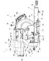
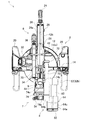
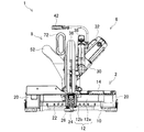
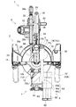
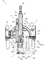
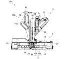
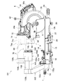
図1は第1形態に係る卓上切断機1の右側面図であり、図2は卓上切断機1の上面図であり、図3は卓上切断機1の前面図である。
卓上切断機1は、作業用机の天板上に据えるベース2と、切断刃4を有する切断機本体6と、ベース2と本体6の間に介装される傾動機構7、複数段スライド機構8及び揺動機構9を備えている。
[Configuration of First Form, etc.]
FIG. 1 is a right side view of the tabletop cutting machine 1 according to the first embodiment, FIG. 2 is a top view of the tabletop cutting machine 1, and FIG. 3 is a front view of the tabletop cutting machine 1.
The tabletop cutting machine 1 includes a base 2 placed on a top plate of a work desk, a cutting machine main body 6 having a cutting blade 4, a tilting mechanism 7 interposed between the base 2 and the main body 6, and a multi-stage slide mechanism. 8 and a swing mechanism 9 are provided.

ベース2は、ベース枠10と、ベース枠10の上側ないし前側においてベース枠10に対し左右に回転可能に設けられるテーブル12と、テーブル12の上側に配置されるフェンス14を備えている。尚、図1において右が前となり、図2において上が前となる。   The base 2 includes a base frame 10, a table 12 provided on the upper side or the front side of the base frame 10 so as to be rotatable to the left and right with respect to the base frame 10, and a fence 14 disposed on the upper side of the table 12. In FIG. 1, the right is the front, and the upper is the front in FIG.

ベース枠10は、左右に脚部20を有しており、前部に複数の切り欠きが円筒面上に並べられたノッチ部22を有している。
テーブル12は、円盤状部12aから前方に長尺直方体状の延長部12bが突出した形状となっており、円盤状部12aがベース枠10の上側に配置され、延長部12bがベース枠10の前側に配置される。円盤状部12aないし延長部12bの上面は水平であり、被加工材を載せることが可能である。テーブル12は、円盤状部12aの中心を通る鉛直軸を中心軸として、左右に回転可能である。
テーブル12は、延長部12bの前端部において、テーブル操作レバー24を有している。テーブル12は、ベース枠10におけるノッチ部22の何れかの切り欠きに対して係合する図示しない係合機構を有している。テーブル操作レバー24は、当該係合機構に対し、切り欠きに対する係合ないしその解除を操作可能な状態で連係しており、よって、テーブル12は、テーブル操作レバー24の操作により、ベース枠10に対し、ノッチ部22の切り欠きに対応した角度で任意に回転移動可能であり、又固定可能である。更に、テーブル12は、延長部12bの前下部において、延長部12bに対し上下移動可能な前脚部26を備えている。加えて、テーブル12の上面には、切断刃4の通るスリットである刃口28aを有する刃口板28が設置されている。
フェンス14は、左右に長い部材であり、各端部がベース枠10の脚部20の上側に配置されている。フェンス14は、前面の大部分が平面(位置決め面)とされており、当該位置決め面に被加工材を当てることが可能となっていて、被加工材の位置決めの用に供される。テーブル12の円盤状部12aの中心軸は、当該位置決め面(の延長面)に含まれる。
The base frame 10 has leg portions 20 on the left and right sides, and has a notch portion 22 in which a plurality of notches are arranged on a cylindrical surface at the front portion.
The table 12 has a shape in which an elongated rectangular parallelepiped extension portion 12 b projects forward from the disc-like portion 12 a, the disc-like portion 12 a is disposed on the upper side of the base frame 10, and the extension portion 12 b is the base frame 10. Arranged on the front side. The upper surface of the disk-shaped part 12a thru | or extension part 12b is horizontal, and it can mount a workpiece. The table 12 can be rotated left and right with a vertical axis passing through the center of the disk-shaped portion 12a as a central axis.
The table 12 has a table operation lever 24 at the front end of the extension 12b. The table 12 has an engagement mechanism (not shown) that engages with any notch of the notch portion 22 in the base frame 10. The table operation lever 24 is linked to the engagement mechanism in a state where it can be engaged with or released from the notch. Therefore, the table 12 is attached to the base frame 10 by the operation of the table operation lever 24. On the other hand, it can be arbitrarily rotated and fixed at an angle corresponding to the notch of the notch 22. Further, the table 12 includes a front leg portion 26 that can move up and down with respect to the extension portion 12b at the front lower portion of the extension portion 12b. In addition, a blade edge plate 28 having a blade edge 28 a that is a slit through which the cutting blade 4 passes is installed on the upper surface of the table 12.
The fence 14 is a member that is long to the left and right, and each end is disposed above the leg 20 of the base frame 10. Most of the front surface of the fence 14 is a flat surface (positioning surface), and a workpiece can be applied to the positioning surface, and is used for positioning the workpiece. The central axis of the disk-shaped part 12a of the table 12 is included in the positioning surface (the extended surface thereof).

切断機本体6は、図示しないギア機構を収容するギアハウジング30と、ギアハウジング30の左側に配置され、当該ギア機構を介して切断刃4を回転する図示しないモータを収容するモータハウジング32と、ギアハウジング30の右側に配置され、切断刃4を一部露出する状態で収容するブレードケース34と、切断刃4の周縁に沿って回転可能であるようにブレードケース34に設置された、切断刃4の外周部の一部を覆う保護カバー36を備えている。
又、切断機本体6は、ギアハウジング30やブレードケース34の上側に配置されるハンドル部38を備えている。ハンドル部38は、その前部において前ループ部38aを有し、その後部において後ループ部38bを有している。前ループ部38aの内周側には、トリガ形式のスイッチレバー40が設けられている。スイッチレバー40は、上記モータと電気的に接続されている。前ループ部38aは、主に切断操作時に用いられる。又、後ループ部38bは、主に持ち運び時に用いられる(キャリングハンドル)。
更に、切断機本体6は、ハンドル部38の上部において、小アーム部とその先端に配される照明部を含む照明具42を備えている。又、切断機本体6は、後ループ部38bの後部から外方へ延びる電源コード44を備えている。電源コード44は、上記モータ等に電気的に接続され、又図示しない電源と接続可能であり、卓上切断機1に対し電源からの電気を導入する。尚、図面において、電源コード44は大部分が省略されている。
The cutting machine body 6 includes a gear housing 30 that houses a gear mechanism (not shown), a motor housing 32 that is arranged on the left side of the gear housing 30 and houses a motor (not shown) that rotates the cutting blade 4 via the gear mechanism, A blade case 34 that is disposed on the right side of the gear housing 30 and accommodates the cutting blade 4 in a partially exposed state, and a cutting blade that is installed in the blade case 34 so as to be rotatable along the periphery of the cutting blade 4 4 is provided with a protective cover 36 that covers a part of the outer peripheral portion of 4.
In addition, the cutting machine body 6 includes a handle portion 38 disposed on the upper side of the gear housing 30 and the blade case 34. The handle portion 38 has a front loop portion 38a at a front portion thereof and a rear loop portion 38b at a rear portion thereof. A trigger type switch lever 40 is provided on the inner peripheral side of the front loop portion 38a. The switch lever 40 is electrically connected to the motor. The front loop portion 38a is mainly used during a cutting operation. The rear loop portion 38b is mainly used for carrying (carrying handle).
Further, the cutting machine main body 6 includes an illumination tool 42 including a small arm portion and an illumination portion arranged at the tip of the small arm portion at the upper portion of the handle portion 38. The cutting machine main body 6 includes a power cord 44 that extends outward from the rear portion of the rear loop portion 38b. The power cord 44 is electrically connected to the motor or the like and can be connected to a power source (not shown), and introduces electricity from the power source to the tabletop cutting machine 1. In the drawing, most of the power cord 44 is omitted.

傾動機構7は、テーブル12の上面に含まれ且つテーブル12の回転中心を通る前後方向の軸の周りで、切断機本体6と複数段スライド機構8を左に傾けて(あるいは傾けないで)固定する。傾動機構7により傾動可能である範囲は、切断機本体6が傾かない(切断刃4が鉛直である)状態から、左に45°程度傾いた状態までである。
傾動機構7は、ベース2(ベース枠10)後部と一体に設けられた保持部50と、保持部50に対し左右に傾動可能に設けられた後述のアーム52を締め付けにより固定し、開放により傾動を許容する傾動移動用レバー54を備えている。
尚、傾動機構7あるいは保持部50について、ベース2あるいは複数段スライド機構8の要素として扱うことが可能である。
The tilting mechanism 7 is fixed by tilting the cutting machine body 6 and the multi-stage slide mechanism 8 to the left (or without tilting) around the longitudinal axis included in the upper surface of the table 12 and passing through the rotation center of the table 12. To do. The range that can be tilted by the tilting mechanism 7 is from a state in which the cutting machine body 6 is not tilted (the cutting blade 4 is vertical) to a state tilted about 45 ° to the left.
The tilting mechanism 7 fixes a holding part 50 provided integrally with the rear part of the base 2 (base frame 10) and an arm 52 (described later) provided so as to be tiltable to the left and right with respect to the holding part 50 by fastening, and tilts by opening. A tilting movement lever 54 is provided.
The tilting mechanism 7 or the holding unit 50 can be handled as an element of the base 2 or the multistage slide mechanism 8.

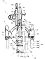
複数段スライド機構8は、切断機本体6を、前後方向に移動させる。複数段スライド機構8は、傾動機構7により切断機本体6を傾動させない場合には、図1〜3の状態から図4〜5に示す状態までにおいて、切断機本体6をスライド移動させる。尚、複数段スライド機構8は、傾動機構7により切断機本体6を傾動させた場合でも、傾動させない場合と同様に前後移動可能である。
複数段スライド機構8は、上述のアーム52と、アーム52の上部から後方へ突出するように設置された2本の第1スライドバー60,60と、各第1スライドバー60の後端部に共通に配置される第1スライドバー止め62と、各第1スライドバー60上を前後に移動可能であり各第1スライドバー60に案内される第1スライド支持部64を備えている。アーム52及び第1スライドバー60,60は、第1スライド案内部を構成し、各第1スライドバー60は、第1案内部材を構成する。
The multistage slide mechanism 8 moves the cutting machine body 6 in the front-rear direction. When the cutting mechanism body 6 is not tilted by the tilt mechanism 7, the multi-stage slide mechanism 8 slides the cutting machine body 6 from the state shown in FIGS. 1 to 3 to the state shown in FIGS. The multi-stage slide mechanism 8 can be moved back and forth even when the cutting machine body 6 is tilted by the tilting mechanism 7 in the same manner as when the tilting mechanism 7 is not tilted.
The multi-stage slide mechanism 8 includes the above-described arm 52, two first slide bars 60, 60 installed so as to protrude rearward from the upper part of the arm 52, and a rear end portion of each first slide bar 60. A first slide bar stop 62 arranged in common and a first slide support portion 64 that can be moved back and forth on each first slide bar 60 and guided to each first slide bar 60 are provided. The arm 52 and the first slide bars 60, 60 constitute a first slide guide portion, and each first slide bar 60 constitutes a first guide member.

アーム52は、上下方向に長い部材であり、アーム下部52aにおいて傾動移動用レバー54と連係されており、又保持部50に傾動可能に支持されている。アーム52は、傾動機構7により左右方向にスイングするものの、前後方向にスライド不能である。又、アーム52は、アーム上部52bがアーム下部52aに対して前方に出るよう、前方に向かい斜行するアーム中央部52cを有している。尚、アーム52について、複数段スライド機構8ではなく傾動機構7あるいはベース2の要素として扱うことが可能である。
第1スライドバー60,60は、前後方向に沿うバーであり、互いに平行である状態で上下に配置され、上の第1スライドバー60が下の第1スライドバー60より平面視で右側となるように配置されている。アーム上部52bと第1スライドバー止め62は、第1スライドバー60,60の配置に合わせ、上に行くほど右に寄るよう右に傾いている。
アーム上部52bは、第1スライドバー60,60の前端部を共に保持しており、当該前端部まで移動してきた第1スライド支持部64を止める。
第1スライドバー止め62は、第1スライドバー60,60の後端部を共に保持しており、当該後端部まで移動してきた第1スライド支持部64を止める。
第1スライド支持部64は、アーム上部52bや第1スライドバー止め62と同様に傾いている第1スライドバー受け部64aと、第1スライドバー受け部64aの前下部から上方へ突出するように設けられた第2スライドバー止め部64bを有する。第1スライドバー受け部64aと第2スライドバー止め部64bは、一体である。第1スライドバー受け部64aは、図示しない上下2個の前後方向の孔において第1スライドバー60,60を受け入れている。当該孔のうち上の孔には、円筒状のベアリング64cが1個配置されており、下の孔には、円筒状のベアリング64c,64cが、前後に2個配置されている。各ベアリング64cは、リニアボールベアリングであり、第1スライドバー60上を移動可能であるように、第1スライドバー60を受け入れている。各ベアリング64cは、第1スライド支持部64の構成要素として扱うことができる。
The arm 52 is a member that is long in the vertical direction, is linked to the tilt moving lever 54 in the arm lower portion 52a, and is supported by the holding portion 50 so as to be tiltable. The arm 52 swings in the left-right direction by the tilt mechanism 7, but cannot slide in the front-rear direction. Further, the arm 52 has an arm center portion 52c that is inclined forward so that the arm upper portion 52b protrudes forward with respect to the arm lower portion 52a. The arm 52 can be handled as an element of the tilting mechanism 7 or the base 2 instead of the multi-stage slide mechanism 8.
The first slide bars 60, 60 are bars that extend in the front-rear direction, and are arranged up and down in a state of being parallel to each other, and the upper first slide bar 60 is on the right side in plan view from the lower first slide bar 60. Are arranged as follows. The arm upper portion 52b and the first slide bar stopper 62 are inclined to the right so as to be closer to the right in accordance with the arrangement of the first slide bars 60, 60.
The arm upper portion 52b holds the front end portions of the first slide bars 60 and 60, and stops the first slide support portion 64 that has moved to the front end portion.
The first slide bar stopper 62 holds the rear end portions of the first slide bars 60 and 60 together, and stops the first slide support portion 64 that has moved to the rear end portion.
The first slide support portion 64 protrudes upward from the first slide bar receiving portion 64a that is inclined in the same manner as the arm upper portion 52b and the first slide bar stopper 62, and the front lower portion of the first slide bar receiving portion 64a. A second slide bar stopper 64b is provided. The first slide bar receiving portion 64a and the second slide bar stopper 64b are integrated. The first slide bar receiving portion 64a receives the first slide bars 60, 60 in two upper and lower front and rear holes (not shown). One cylindrical bearing 64c is arranged in the upper hole among the holes, and two cylindrical bearings 64c and 64c are arranged in the front and rear in the lower hole. Each bearing 64 c is a linear ball bearing, and receives the first slide bar 60 so as to be movable on the first slide bar 60. Each bearing 64 c can be handled as a component of the first slide support portion 64.

又、複数段スライド機構8は、第1スライド支持部64の第2スライドバー止め部64bから前方へ突出するように設置された第2スライドバー70,70と、各第2スライドバー70の前端部に共通に配置される第2スライドバー止め72と、第2スライドバー70,70上を前後に移動可能であり第2スライドバー70,70に案内される第2スライド支持部74を備えている。第2スライドバー70,70は、第2スライド案内部を構成し、各第2スライドバー70は、第2案内部材を構成する。
第2スライドバー70,70は、上下に配置されており、下のものの真上に上のものが配置される。下の第2スライドバー70は、下の第1スライドバー60の左上に位置する。
第2スライドバー止め72は、上下方向に沿うように配置される。
第1スライド支持部64の第2スライドバー止め部64bは、各第2スライドバー70の後端部を共に保持しており、当該後端部まで移動してきた第2スライド支持部74を止める。第2スライドバー止め72は、各第2スライドバー70の前端部を共に保持しており、当該前端部まで移動してきた第2スライド支持部74を止める。
第2スライド支持部74は、上下方向に沿う厚板状の部分である第2スライド支持部基部74aと、第2スライド支持部基部74aの右面下部から下方に突出する状態で第2スライド支持部基部74aに固定した連結板部74bを有している。第2スライド支持部基部74aに設けられた図示しない上下2個の前後方向の孔において第2スライドバー70をそれぞれ受け入れている。当該上下の孔には、何れか一方の第2スライドバー70を受け入れる円筒状のベアリング74c,74c・・が、ベアリング64c,64c・・と同様に設置されている。連結板部74bは、前後上下に広がっており、その右側に、ブレードケース34の左側後部が配置されている。
尚、第2スライド支持部74について、揺動機構9あるいは切断機本体6の要素として扱うことが可能である。
Further, the multi-stage slide mechanism 8 includes second slide bars 70 and 70 installed so as to protrude forward from the second slide bar stopper 64b of the first slide support 64, and the front ends of the second slide bars 70. A second slide bar stopper 72 disposed in common with the second slide bar, and a second slide support portion 74 that can move back and forth on the second slide bars 70 and 70 and is guided by the second slide bars 70 and 70. Yes. The second slide bars 70, 70 constitute a second slide guide part, and each second slide bar 70 constitutes a second guide member.
The second slide bars 70, 70 are arranged above and below, and the upper one is arranged directly above the lower one. The lower second slide bar 70 is located at the upper left of the lower first slide bar 60.
The second slide bar stopper 72 is disposed along the vertical direction.
The second slide bar stop portion 64b of the first slide support portion 64 holds the rear end portion of each second slide bar 70 together, and stops the second slide support portion 74 that has moved to the rear end portion. The second slide bar stopper 72 holds the front end portion of each second slide bar 70 together, and stops the second slide support portion 74 that has moved to the front end portion.
The second slide support portion 74 includes a second slide support portion base portion 74a that is a thick plate-like portion along the vertical direction, and a second slide support portion that protrudes downward from the lower right side of the second slide support portion base portion 74a. It has the connection board part 74b fixed to the base 74a. The second slide bar 70 is received in two front and rear holes (not shown) provided in the second slide support base 74a. Cylindrical bearings 74c, 74c,... For receiving either one of the second slide bars 70 are installed in the upper and lower holes in the same manner as the bearings 64c, 64c,. The connecting plate portion 74b extends from front to back and up and down, and the left rear portion of the blade case 34 is disposed on the right side thereof.
The second slide support 74 can be handled as an element of the swing mechanism 9 or the cutting machine body 6.

複数段スライド機構8は、第1スライド支持部64と第2スライド支持部74を有する、2段のスライド機構となっている。
第1スライド支持部64を案内する第1スライドバー60,60が、上の第1スライドバー60につき下の第1スライドバー60より平面視で右側に位置する状態で設置されている一方、第2スライド支持部74を案内する第2スライドバー70,70が、上の第2スライドバー70につき、各第1スライドバー60より左方にある下の第2スライドバー70の真上に配置した状態で設置されており、第1スライドバー60,60と第2スライドバー70,70は、左右方向において互いにずれている。
又、複数段スライド機構8における各第1スライドバー60後端の第1スライドバー止め62が、卓上切断機1における最後部となっている。
The multi-stage slide mechanism 8 is a two-stage slide mechanism having a first slide support part 64 and a second slide support part 74.
The first slide bars 60, 60 that guide the first slide support portion 64 are installed in a state of being located on the right side in plan view with respect to the upper first slide bar 60 from the lower first slide bar 60. The second slide bars 70 and 70 for guiding the two slide support portions 74 are arranged directly above the lower second slide bar 70 on the left side of each first slide bar 60 with respect to the upper second slide bar 70. The first slide bars 60, 60 and the second slide bars 70, 70 are displaced from each other in the left-right direction.
The first slide bar stopper 62 at the rear end of each first slide bar 60 in the multi-stage slide mechanism 8 is the last part in the tabletop cutting machine 1.

揺動機構9は、切断機本体6を、上下に揺動可能に支持するものである。当該揺動の範囲は、図示の状態(切断刃4の下縁部が刃口28aに入っている状態)から、50°程度上方に移動するまでである。
揺動機構9は、連結板部74bとブレードケース34後部を通される揺動用軸80を有する。
揺動機構9により切断機本体6を上方に移動した場合、その揺動に連動して、保護カバー36が回転し、切断刃4の上方ないし前方に位置していた状態(図示の状態)から、切断刃4の前方ないし下方に位置する状態となる。
尚、揺動機構9について、複数段スライド機構8あるいは切断機本体6の要素として扱うことが可能である。
The swing mechanism 9 supports the cutting machine body 6 so as to be swingable up and down. The range of the swing is from the state shown in the figure (the state in which the lower edge of the cutting blade 4 is in the blade opening 28a) until it moves upward by about 50 °.
The swing mechanism 9 has a swing shaft 80 through which the connecting plate portion 74b and the rear portion of the blade case 34 are passed.
When the cutting machine body 6 is moved upward by the swing mechanism 9, the protective cover 36 is rotated in conjunction with the swing, and is from the state (shown in the figure) located above or in front of the cutting blade 4. In this state, the cutting blade 4 is positioned in front of or below the cutting blade 4.
The swing mechanism 9 can be handled as an element of the multi-stage slide mechanism 8 or the cutting machine body 6.

[第1形態の動作等]
このような卓上切断機1の動作例を説明する。
作業者は、ベース2を作業机の天面等に設置し、適宜、切断機本体6を前方に位置させ、傾動機構7により切断機本体6の傾きを決定して、テーブル12の回転位置やフェンス14の位置を調節し、テーブル12に被加工材を置く。そして、ハンドル部38を把持し、切断機本体6を図示の状態に下げて、スイッチレバー40を引くと、電源コード44を介してモータへの給電がなされ、切断刃4が回転する。
[Operation of the first form, etc.]
An example of the operation of the tabletop cutting machine 1 will be described.
The operator installs the base 2 on the top surface of the work desk, appropriately positions the cutting machine body 6 forward, determines the inclination of the cutting machine body 6 by the tilt mechanism 7, and determines the rotational position of the table 12. The position of the fence 14 is adjusted, and the workpiece is placed on the table 12. And if the handle | steering-wheel part 38 is hold | gripped and the cutting machine main body 6 is lowered | hung to the state of illustration and the switch lever 40 is pulled, electric power will be supplied to a motor via the power cord 44, and the cutting blade 4 will rotate.

この状態で、作業者がハンドル部38を後方に押していくと、切断機本体6が複数段スライド機構8により後方に移動し、テーブル12上の被加工材に、回転する切断刃4が当たって、被加工材が切断されていく。
切断機本体6を最前方に位置させると(図4〜5)、第1スライド支持部64と第2スライド支持部74が双方とも最前方に位置し、切断刃4の下縁部が刃口28aの前端部に位置する。又、切断機本体6を最後方に位置させると(図1〜3)、第1スライド支持部64と第2スライド支持部74が双方とも最後方に位置し、切断刃4の下縁部が刃口28aの後端部に位置する。
切断機本体6のスライドによる前後移動において、第1スライド支持部64や第2スライド支持部74、各第2スライドバー70は移動するが、各第1スライドバー60やアーム52は移動しない。
In this state, when the operator pushes the handle portion 38 rearward, the cutting machine main body 6 is moved rearward by the multi-stage slide mechanism 8, and the rotating cutting blade 4 hits the workpiece on the table 12. The workpiece is cut.
When the cutting machine body 6 is positioned at the forefront (FIGS. 4 to 5), both the first slide support portion 64 and the second slide support portion 74 are positioned at the forefront, and the lower edge of the cutting blade 4 is the blade edge. It is located at the front end of 28a. When the cutting machine body 6 is positioned at the rearmost position (FIGS. 1 to 3), both the first slide support section 64 and the second slide support section 74 are positioned at the rearmost position, and the lower edge of the cutting blade 4 is It is located at the rear end of the blade opening 28a.
In the longitudinal movement by the slide of the cutting machine body 6, the first slide support part 64, the second slide support part 74, and the second slide bars 70 move, but the first slide bars 60 and the arms 52 do not move.

[第1形態の効果等]
以上の卓上切断機1は、被加工材が載せられるベース2と、当該被加工材を切断する切断刃4が設けられた切断機本体6と、ベース2と切断機本体6に介在する複数段スライド機構8とを備えており、複数段スライド機構8は、前後方向へのスライドが不能な状態でベース2に接続される各第1スライドバー60及びアーム52と、前後方向へのスライドが可能な状態で、第1スライドバー60,60に案内される第1スライド支持部64と、第1スライド支持部64に支持される各第2スライドバー70と、卓上切断機1の最後部(第1スライドバー止め62)より前方において前後方向へのスライドが可能な状態で、第2スライドバー70,70に案内される第2スライド支持部74とを含んでいる。
よって、第1スライド支持部64及び第2スライド支持部74に係る2段のスライドにより、スライド量を充分に確保することができ、更に、同等のスライド量となる1段のスライド機構と比べ、スライド支持部案内用のスライドバーに係る前後の大きさが切断機本体6の後方移動時に小さくなって、切断時に邪魔になり難い。又、第1スライド支持部64を案内する各第1スライドバー60及びアーム52がベース2に前後方向へのスライドが不能な状態で接続されると共に、第2スライド支持部74が第1スライド支持部64の前方において案内されることにより、切断機本体6の前後移動時に第1スライドバー止め62より後方に複数段スライド機構8が突出することがなく、卓上切断機1の後部を壁際に設置した際に複数段スライド機構8が壁に当たる事態を防止することができ、スライド量の減らない状態で壁際に設置可能な設置し易いものとすることができる。
[Effects of the first embodiment]
The tabletop cutting machine 1 includes a base 2 on which a workpiece is placed, a cutting machine body 6 provided with a cutting blade 4 for cutting the workpiece, and a plurality of stages interposed between the base 2 and the cutting machine body 6. The multi-stage slide mechanism 8 is capable of sliding in the front-rear direction and the first slide bar 60 and the arm 52 connected to the base 2 in a state in which the slide in the front-rear direction is impossible. In this state, the first slide support part 64 guided by the first slide bars 60, 60, the second slide bars 70 supported by the first slide support part 64, and the last part (first part of the tabletop cutting machine 1). The first slide bar stop 62) includes a second slide support portion 74 guided by the second slide bars 70 and 70 in a state in which the slide in the front-rear direction is possible.
Therefore, the two-stage slide related to the first slide support part 64 and the second slide support part 74 can sufficiently secure the slide amount, and moreover, compared to the one-stage slide mechanism having an equivalent slide amount, The front / rear size of the slide support portion guide slide bar is reduced when the cutting machine body 6 is moved rearward, and does not easily interfere with cutting. Each first slide bar 60 and arm 52 for guiding the first slide support portion 64 are connected to the base 2 in a state in which the slide in the front-rear direction is impossible, and the second slide support portion 74 is the first slide support. By being guided in front of the section 64, the multi-stage slide mechanism 8 does not protrude behind the first slide bar stopper 62 when the cutting machine body 6 moves back and forth, and the rear portion of the tabletop cutting machine 1 is installed near the wall. In this case, it is possible to prevent the multi-stage slide mechanism 8 from hitting the wall, and it is possible to easily install the multi-stage slide mechanism 8 that can be installed near the wall without reducing the slide amount.

又、第1スライド支持部64を案内する各第1スライドバー60と、第2スライド支持部74を案内する各第2スライドバー70が設けられており、各第1スライドバー60と各第2スライドバー70は、左右方向において互いにずれているので、第1スライド支持部64と第2スライド支持部74が互いに引っ掛かる事態を防止することができ、切断機本体6の前後移動時の操作性が良好であり且つ設置し易い卓上切断機1における、切断機本体6の前後移動に係る動作を更に円滑なものとすることができる。
更に、第1スライド支持部64や第2スライド支持部74を案内するものは、第1スライドバー60や第2スライドバー70であるため、第1スライド支持部64や第2スライド支持部74を案内する機構をシンプルに構成することができる。
又更に、各第1スライドバー60及びアーム52や、各第2スライドバー70は、ベース2の上方に配置されているため、各第1スライドバー60や各第2スライドバー70とベース2を上下にオーバーラップさせることができ、前後方向あるいは左右方向においてコンパクト化を図ることができる。
加えて、各第1スライドバー60及びアーム52は、第1スライド支持部64を案内する各第1スライドバー60、及び各第1スライドバー60とベース2の間に介在するアーム52を含んでおり、アーム52は、アーム上部52bがアーム下部52aに対して前方に位置する形状となっており、各第1スライドバー60は、アーム上部52bの後部から後方へ突出する状態で、アーム52に固定されているので、第1スライド支持部64の前方でスライドする第2スライド支持部74や、これを案内する各第2スライドバー70との前後方向のバランスを確保することができ、動作を円滑なものとすることができるし、各第1スライドバー60の後端(第1スライドバー止め62)をより前方に配置して、前後方向にコンパクトにすることができる。
Each first slide bar 60 for guiding the first slide support portion 64 and each second slide bar 70 for guiding the second slide support portion 74 are provided, and each first slide bar 60 and each second slide bar 70 are provided. Since the slide bar 70 is displaced from each other in the left-right direction, it is possible to prevent the first slide support portion 64 and the second slide support portion 74 from being caught with each other, and the operability when the cutting machine body 6 moves back and forth is improved. In the tabletop cutting machine 1 that is good and easy to install, the operation related to the back and forth movement of the cutting machine body 6 can be made smoother.
Furthermore, since the first slide bar 60 and the second slide bar 70 guide the first slide support part 64 and the second slide support part 74, the first slide support part 64 and the second slide support part 74 are connected to each other. The guiding mechanism can be configured simply.
Furthermore, since each first slide bar 60 and arm 52 and each second slide bar 70 are arranged above the base 2, each first slide bar 60, each second slide bar 70 and the base 2 are connected. It can be made to overlap up and down, and compactness can be achieved in the front-rear direction or the left-right direction.
In addition, each first slide bar 60 and each arm 52 include each first slide bar 60 that guides the first slide support portion 64 and each arm 52 that is interposed between each first slide bar 60 and the base 2. The arm 52 has a shape in which the arm upper part 52b is positioned forward with respect to the arm lower part 52a, and each first slide bar 60 projects from the rear part of the arm upper part 52b rearward. Since it is fixed, it is possible to secure a balance in the front-rear direction with the second slide support part 74 that slides in front of the first slide support part 64 and each second slide bar 70 that guides the second slide support part 74, and the operation. It can be made smooth, and the rear end (first slide bar stopper 62) of each first slide bar 60 is arranged more forward so as to be compact in the front-rear direction. It can be.

[第2形態の構成等]
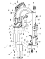
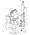
図6は第2形態に係る卓上切断機101の図1相当図であり、図7は第2形態の図2相当図であり、図8は第2形態の図3相当図であり、図9は第2形態の図4相当図であり、図10は第2形態の図5相当図である。
第2形態の卓上切断機101は、複数段スライド機構を除き、第1形態と同様に構成される。以下、第1形態と同様の部材には同じ符号を付し、適宜説明を省略する。
[Configuration of second form, etc.]
6 is a view corresponding to FIG. 1 of the tabletop cutting machine 101 according to the second embodiment, FIG. 7 is a view corresponding to FIG. 2 of the second embodiment, and FIG. 8 is a view corresponding to FIG. FIG. 10 is a diagram corresponding to FIG. 4 of the second embodiment, and FIG. 10 is a diagram corresponding to FIG. 5 of the second embodiment.
The desktop cutter 101 of the second form is configured in the same manner as the first form except for the multi-stage slide mechanism. Hereinafter, members similar to those in the first embodiment are denoted by the same reference numerals, and description thereof will be omitted as appropriate.

第2形態の複数段スライド機構108は、アーム152と、アーム152の上部から前方へ突出するように設置された各第1スライドバー160と、各第1スライドバー160の前端部に共通に配置される第1スライドバー止め162と、第1スライドバー160,160上を前後に移動可能であり第1スライドバー160,160に案内される第1スライド支持部164を備えている。各第1スライドバー160及びアーム152は、第1スライド案内部を構成し、各第1スライドバー160は、第1案内部材を構成する。   The multi-stage slide mechanism 108 of the second form is arranged in common at the arm 152, each first slide bar 160 installed so as to protrude forward from the upper part of the arm 152, and the front end portion of each first slide bar 160. The first slide bar stop 162 and the first slide support portion 164 that can move back and forth on the first slide bars 160 and 160 and are guided by the first slide bars 160 and 160 are provided. Each first slide bar 160 and arm 152 constitute a first slide guide part, and each first slide bar 160 constitutes a first guide member.

アーム152は、上下方向に長い部材であり、アーム下部152aにおいて傾動移動用レバー54と連係されており、又保持部50に傾動可能に支持されている。アーム152は、傾動機構7により左右方向にスイングするものの、前後方向にスライド不能である。又、アーム152は、アーム上部152bがアーム下部152aに対して後方に出るよう、後方に向かい斜行するアーム中央部152cを有している。
第1スライドバー160,160は、前後方向に沿っており互いに平行である状態で上下に配置され、上の第1スライドバー160が下の第1スライドバー160より平面視で右側となるように配置されている。アーム上部152bと第1スライドバー止め162は、第1スライドバー160,160の配置に合わせ、上に行くほど右に寄るよう右に傾いている。
アーム上部152bは、第1スライドバー160,160の後端部を共に保持しており、当該後端部まで移動してきた第1スライド支持部164を止める。
第1スライドバー止め162は、第1スライドバー160,160の前端部を共に保持しており、当該前端部まで移動してきた第1スライド支持部64を止める。
第1スライド支持部164は、アーム上部152bや第1スライドバー止め162と同様に傾いている第1スライドバー受け部164aと、第1スライドバー受け部64aの後下部から上方へ突出するように設けられた第2スライドバー止め部164bと、これらを繋ぐ連結部164cを有する。第1スライドバー受け部164a、第2スライドバー止め部164b、及び連結部164cは、一体である。第1スライドバー受け部164aは、図示しない上下2個の前後方向の孔において第1スライドバー160,160を受け入れている。当該上下の孔には、何れか一方の第1スライドバー160を受け入れる円筒状のベアリング164d,164d・・が、ベアリング74c,74c・・と同様に設置されている。
The arm 152 is a member that is long in the vertical direction, is linked to the tilt movement lever 54 in the arm lower portion 152a, and is supported by the holding portion 50 so as to be tiltable. The arm 152 swings in the left-right direction by the tilt mechanism 7 but cannot slide in the front-rear direction. Further, the arm 152 has an arm center portion 152c that is inclined rearward so that the arm upper portion 152b protrudes rearward with respect to the arm lower portion 152a.
The first slide bars 160 and 160 are arranged vertically along the front-rear direction and parallel to each other so that the upper first slide bar 160 is on the right side of the lower first slide bar 160 in plan view. Has been placed. The arm upper portion 152b and the first slide bar stopper 162 are inclined to the right so as to be closer to the right in accordance with the arrangement of the first slide bars 160 and 160.
The arm upper portion 152b holds the rear end portions of the first slide bars 160 and 160, and stops the first slide support portion 164 that has moved to the rear end portion.
The first slide bar stop 162 holds both the front end portions of the first slide bars 160 and 160 and stops the first slide support portion 64 that has moved to the front end portion.
The first slide support portion 164 protrudes upward from the first slide bar receiving portion 164a which is inclined in the same manner as the arm upper portion 152b and the first slide bar stopper 162 and the rear lower portion of the first slide bar receiving portion 64a. It has the 2nd slide bar stop part 164b provided, and the connection part 164c which connects these. The first slide bar receiving portion 164a, the second slide bar stopper 164b, and the connecting portion 164c are integrated. The first slide bar receiving portion 164a receives the first slide bars 160, 160 in two upper and lower front and rear holes (not shown). Cylindrical bearings 164d, 164d,... For receiving one of the first slide bars 160 are installed in the upper and lower holes in the same manner as the bearings 74c, 74c,.

又、複数段スライド機構108は、第1スライド支持部164の第2スライドバー止め部164bから前方へ突出するように設置された第2スライドバー70,70と、各第2スライドバー70の前端部に共通に配置される第2スライドバー止め72と、第2スライドバー70,70上を前後に移動可能であり第2スライドバー70,70に案内される第2スライド支持部74を備えている。第2スライドバー70,70は、第2スライド案内部を構成し、各第2スライドバー70は、第2案内部材を構成する。
第1スライド支持部164の第2スライドバー止め部164bは、第2スライドバー70,70の後端部を共に保持しており、当該後端部まで移動してきた第2スライド支持部74を止める。第2スライドバー止め72は、第2スライドバー70,70の前端部を共に保持しており、当該前端部まで移動してきた第2スライド支持部74を止める。
In addition, the multi-stage slide mechanism 108 includes second slide bars 70, 70 installed so as to protrude forward from the second slide bar stopper 164 b of the first slide support 164, and the front end of each second slide bar 70. A second slide bar stopper 72 disposed in common with the second slide bar, and a second slide support portion 74 that can move back and forth on the second slide bars 70 and 70 and is guided by the second slide bars 70 and 70. Yes. The second slide bars 70, 70 constitute a second slide guide part, and each second slide bar 70 constitutes a second guide member.
The second slide bar stopper 164b of the first slide support 164 holds the rear end portions of the second slide bars 70, 70 together, and stops the second slide support portion 74 that has moved to the rear end portion. . The second slide bar stopper 72 holds both the front end portions of the second slide bars 70 and 70 and stops the second slide support portion 74 that has moved to the front end portion.

複数段スライド機構108は、第1スライド支持部164と第2スライド支持部74を有する、2段のスライド機構となっている。
第1スライド支持部164を案内する第1スライドバー160,160が、上の第1スライドバー160につき下の第1スライドバー160より平面視で右側に位置する状態で設置されている一方、第2スライド支持部74を案内する第2スライドバー70,70が、上の第2スライドバー70につき、各第1スライドバー160より左方にある下の第2スライドバー70の真上に配置した状態で設置されており、第1スライドバー160,160と第2スライドバー70,70は、左右方向において互いにオフセットしている。
又、複数段スライド機構108におけるアーム上部152bが、卓上切断機101における最後部となっている。
The multi-stage slide mechanism 108 is a two-stage slide mechanism having a first slide support part 164 and a second slide support part 74.
The first slide bars 160, 160 that guide the first slide support part 164 are installed on the upper first slide bar 160 in a state of being positioned on the right side in plan view with respect to the lower first slide bar 160, The second slide bars 70, 70 for guiding the two slide support portions 74 are arranged directly above the lower second slide bar 70 on the left side of each first slide bar 160 with respect to the upper second slide bar 70. The first slide bar 160, 160 and the second slide bar 70, 70 are offset from each other in the left-right direction.
Further, the upper arm portion 152 b in the multi-stage slide mechanism 108 is the last part in the tabletop cutting machine 101.

[第2形態の動作等]
卓上切断機101の動作例を説明する。
作業者がハンドル部38を後方に押していくと、切断機本体6が複数段スライド機構108により後方に移動し、テーブル12上の被加工材に、回転する切断刃4が当たって、被加工材が切断されていく。
切断機本体6を最前方に位置させると(図9〜10)、第1スライド支持部164と第2スライド支持部74が双方とも最前方に位置し、切断刃4の下縁部が刃口28aの前端部に位置する。又、切断機本体6を最後方に位置させると(図6〜8)、第1スライド支持部164と第2スライド支持部74が双方とも最後方に位置し、切断刃4の下縁部が刃口28aの後端部に位置する。
切断機本体6のスライドによる前後移動において、第1スライド支持部164や第2スライド支持部74、第2スライドバー70,70は移動するが、第1スライドバー160,160やアーム152は移動しない。
[Operation of the second form, etc.]
An operation example of the tabletop cutting machine 101 will be described.
When the operator pushes the handle portion 38 rearward, the cutting machine main body 6 is moved rearward by the multi-stage slide mechanism 108, and the rotating cutting blade 4 hits the workpiece on the table 12, so that the workpiece is processed. Will be cut off.
When the cutting machine body 6 is positioned at the forefront (FIGS. 9 to 10), both the first slide support portion 164 and the second slide support portion 74 are positioned at the forefront, and the lower edge of the cutting blade 4 is the blade edge. It is located at the front end of 28a. When the cutting machine body 6 is positioned at the rearmost position (FIGS. 6 to 8), both the first slide support section 164 and the second slide support section 74 are positioned at the rearmost position, and the lower edge of the cutting blade 4 is It is located at the rear end of the blade opening 28a.
In the longitudinal movement by the slide of the cutting machine body 6, the first slide support part 164, the second slide support part 74, and the second slide bars 70, 70 move, but the first slide bars 160, 160 and the arm 152 do not move. .

[第2形態の効果等]
以上の卓上切断機101は、被加工材が載せられるベース2と、当該被加工材を切断する切断刃4が設けられた切断機本体6と、ベース2と切断機本体6に介在する複数段スライド機構108とを備えており、複数段スライド機構108は、前後方向へのスライドが不能な状態でベース2に接続される各第1スライドバー160及びアーム152と、前後方向へのスライドが可能な状態で、第1スライドバー160,160に案内される第1スライド支持部164と、第1スライド支持部164に支持される各第2スライドバー70と、卓上切断機1の最後部(第1スライドバー160後端のアーム上部152a)より前方において前後方向へのスライドが可能な状態で、第2スライドバー70,70に案内される第2スライド支持部74とを含んでいる。
よって、第1スライド支持部164及び第2スライド支持部74に係る2段のスライドにより、スライド量を充分に確保することができ、更に、同等のスライド量となる1段のスライド機構と比べ、スライド支持部案内用のスライドバーに係る前後の大きさが切断機本体6の後方移動時に小さくなって、切断時に邪魔になり難い。又、第1スライド支持部164を案内する各第1スライドバー160及びアーム152がベース2に前後方向へのスライドが不能な状態で接続されると共に、第2スライド支持部74が第1スライド支持部164の前方に支持されることにより、切断機本体6の前後移動時にアーム152より後方に複数段スライド機構108が突出することがなく、卓上切断機101の後部を壁際に設置した際に複数段スライド機構108が壁に当たる事態を防止することができ、スライド量の減らない状態で壁際に設置可能な設置し易いものとすることができる。
[Effects of the second embodiment, etc.]
The tabletop cutting machine 101 described above includes a base 2 on which a workpiece is placed, a cutting machine body 6 provided with a cutting blade 4 for cutting the workpiece, and a plurality of stages interposed between the base 2 and the cutting machine body 6. The multi-stage slide mechanism 108 is capable of sliding in the front-rear direction and the first slide bar 160 and the arm 152 connected to the base 2 in a state in which the slide in the front-rear direction is impossible. In this state, the first slide support portions 164 guided by the first slide bars 160, 160, the second slide bars 70 supported by the first slide support portions 164, and the last portion of the tabletop cutting machine 1 (first A second slide support portion 74 guided by the second slide bars 70, 70 in a state in which the slide in the front-rear direction is possible in front of the arm upper portion 152a) at the rear end of the first slide bar 160; Which comprise.
Therefore, the slide amount of the two stages related to the first slide support part 164 and the second slide support part 74 can sufficiently secure the slide amount, and moreover, compared to the one-stage slide mechanism having an equivalent slide amount, The front / rear size of the slide support portion guide slide bar is reduced when the cutting machine body 6 is moved rearward, and does not easily interfere with cutting. Each first slide bar 160 and arm 152 for guiding the first slide support portion 164 are connected to the base 2 in a state in which the slide in the front-rear direction is impossible, and the second slide support portion 74 is the first slide support. By being supported in front of the part 164, the multi-stage slide mechanism 108 does not protrude rearward from the arm 152 when the cutting machine body 6 moves back and forth, and a plurality of parts when the rear part of the tabletop cutting machine 101 is installed near the wall. It is possible to prevent the step slide mechanism 108 from hitting the wall, and it is possible to easily install it so that it can be installed near the wall without reducing the sliding amount.

又、第1スライド支持部164を案内する各第1スライドバー160と、第2スライド支持部74を案内する各第2スライドバー70が設けられており、各第1スライドバー160と各第2スライドバー70は、左右方向において互いにずれているので、第1スライド支持部164と第2スライド支持部74が互いに引っ掛かる事態を防止することができ、切断機本体6の前後移動時の操作性が良好であり且つ設置し易い卓上切断機101における、切断機本体6の前後移動に係る動作を更に円滑なものとすることができる。
更に、第1スライド支持部164や第2スライド支持部74を案内するものは、各第1スライドバー160や各第2スライドバー70であるため、第1スライド支持部64や第2スライド支持部74を案内する機構をシンプルに構成することができる。
又更に、各第1スライドバー160及びアーム52や、各第2スライドバー70は、ベース2の上方に配置されているため、第1スライドバー160や第2スライドバー70とベース2を上下にオーバーラップさせることができ、前後方向あるいは左右方向においてコンパクト化を図ることができる。
Each first slide bar 160 for guiding the first slide support portion 164 and each second slide bar 70 for guiding the second slide support portion 74 are provided, and each first slide bar 160 and each second slide bar 70 are provided. Since the slide bar 70 is displaced from each other in the left-right direction, it is possible to prevent the first slide support part 164 and the second slide support part 74 from being caught with each other, and the operability when the cutting machine body 6 moves back and forth is improved. The operation related to the back and forth movement of the cutting machine body 6 in the tabletop cutting machine 101 that is good and easy to install can be made smoother.
Further, since the first slide support section 164 and the second slide support section 74 are guided by the first slide bar 160 and the second slide bar 70, the first slide support section 64 and the second slide support section are provided. The mechanism for guiding 74 can be configured simply.
Furthermore, since each first slide bar 160 and arm 52 and each second slide bar 70 are disposed above the base 2, the first slide bar 160, the second slide bar 70 and the base 2 are moved up and down. It can be made to overlap and can be made compact in the front-back direction or the left-right direction.

[上記形態の変更例等]
尚、本発明は上記形態に限定されず、例えば次のような変更を適宜施すことができる。
複数段スライド機構8,108を、3段のスライド機構とする。
より詳しくは、第2スライド支持部74を、第1スライド支持部64,164と同様に形成し、第3スライドバーを有するものとする。第3スライドバーは、第2スライド支持部74の前方に突出させても良いし、第1スライドバー60,160の後端より常に前方にある状態であれば、第2スライド支持部74の後方に突出させても良い。
又、第3スライドバーには、第3スライド支持部をスライド可能に配置し、その第3スライド支持部に、揺動機構9を介して切断機本体6を取り付ける。更に、第3スライドバーに、第3スライドバー止めを配することができる。尚、第3スライドバーが第1スライドバー60,160の後端より常に前方にある状態について換言すると、第1スライド支持部ないし第3スライド支持部が何れも最後方に位置した場合に、第3スライド支持部が第1スライドバー60,160の後端より前方にある、ということになる。又、第3スライドバーや第3スライド支持部につき、第1スライドバー60,160の後端より後方に突出する別部材を有する、上記形態とは別形状の卓上切断機において、その卓上切断機の最後部より前に配置することができる。更に、このような卓上切断機において、第2スライドバーを第1スライド支持部の後部から後方に突出させる(ただし卓上切断機の最後部より常に前になるようにする)ことができる。
同様に、複数段スライド機構8,108を、4段以上のスライド機構とすることも可能である。
[Examples of changes to the above form]
In addition, this invention is not limited to the said form, For example, the following changes can be given suitably.
The multi-stage slide mechanisms 8 and 108 are three-stage slide mechanisms.
More specifically, the second slide support portion 74 is formed in the same manner as the first slide support portions 64 and 164 and has a third slide bar. The third slide bar may be protruded forward of the second slide support part 74, and if it is always in front of the rear ends of the first slide bars 60, 160, the rear of the second slide support part 74. You may make it project.
A third slide support portion is slidably disposed on the third slide bar, and the cutting machine main body 6 is attached to the third slide support portion via a swing mechanism 9. Furthermore, a third slide bar stop can be arranged on the third slide bar. In other words, when the third slide bar is always in front of the rear ends of the first slide bars 60 and 160, the first slide support portion to the third slide support portion are all located at the rearmost position. That is, the three slide support portions are in front of the rear ends of the first slide bars 60 and 160. Further, in the table cutting machine having a different shape from the above-described form, the table cutting machine has another member protruding rearward from the rear ends of the first slide bars 60 and 160 for the third slide bar and the third slide support portion. It can be placed before the last part. Further, in such a tabletop cutting machine, the second slide bar can be protruded rearward from the rear portion of the first slide support portion (however, always in front of the rearmost portion of the tabletop cutting machine).
Similarly, the multi-stage slide mechanisms 8 and 108 can be four-stage or more slide mechanisms.

3段以上のスライド機構について、次のように述べることができる。
即ち、第n−1のスライド支持部に支持される第nのスライド案内部と、卓上切断機の最後部(第1スライドバーの後端又は当該後端に取り付けられる部材等)より前方において前後方向へのスライドが可能な状態で、第nのスライド案内部に案内される第nのスライド支持部が更に設けられる。
ここで、nは、3段の場合は3であり、4段の場合は3と4であり、5段の場合は、3と4と5であり、以下同様である。これを式で表すと、n={3}or{3,4}or{3,4,5}or・・となる。
尚、このような3段以上のスライド機構であっても、第1スライド支持部と、卓上切断機の最後部より前方でスライドする第2スライド支持部を含んでいることに変わりはない。
The slide mechanism having three or more stages can be described as follows.
That is, the nth slide guide part supported by the n-1th slide support part and the front and rear in front of the last part of the tabletop cutting machine (the rear end of the first slide bar or a member attached to the rear end). An n-th slide support portion that is guided by the n-th slide guide portion in a state in which the slide in the direction is possible is further provided.
Here, n is 3 for 3 stages, 3 and 4 for 4 stages, 3, 4 and 5 for 5 stages, and so on. This can be expressed by an equation: n = {3} or {3,4} or {3,4,5} or.
In addition, even if it is such a slide mechanism of 3 steps | paragraphs or more, it does not change that it includes the 1st slide support part and the 2nd slide support part which slides ahead from the last part of a tabletop cutting machine.

ベース2においてテーブル12を省略したり、傾動機構7を省略したり、切断機本体6のハンドル部38のループ数を1又は3以上としたり、スイッチレバー40をプッシュスイッチとしたり、照明具42を省略したりする等、適宜部材や機構を省略し、変更しあるいは追加する。
ギアハウジング30とモータハウジング32を統合し、あるいはギアハウジング30を分割する等、各種ハウジングやケースの分け方を変える。
各スライド支持部の案内を、1本又は3本以上のスライドバーによるものとしたり、ボールネジによるものとしたり、ベルトやチェーンによるものとしたり、これらの組合せとしたりする。
電源コード44による給電に変えて、バッテリによる給電とする。そのバッテリを、ベース2や切断機本体6等に装着可能にする。
In the base 2, the table 12 is omitted, the tilting mechanism 7 is omitted, the number of loops of the handle portion 38 of the cutting machine body 6 is 1 or 3 or more, the switch lever 40 is a push switch, The members and mechanisms are appropriately omitted, changed, or added.
The way of dividing various housings and cases is changed, for example, the gear housing 30 and the motor housing 32 are integrated or the gear housing 30 is divided.
The guide of each slide support part is made by one or more slide bars, a ball screw, a belt or a chain, or a combination thereof.
Instead of power supply by the power cord 44, power supply by a battery is used. The battery can be attached to the base 2, the cutting machine body 6 or the like.

1,101・・卓上切断機、2・・ベース、4・・切断刃、6・・切断機本体、8,108・・複数段スライド機構、52,152・・アーム(第1のスライド案内部の一部)、52a,152a・・アーム下部、52b・・アーム上部、60,160・・第1スライドバー(第1のスライド案内部の一部,第1の案内部材)、62・・第1スライドバー止め(各第1スライドバー60の後端、卓上切断機1の最後部)、64,164・・第1スライド支持部、70・・第2スライドバー(第2のスライド案内部)、74・・第2スライド支持部、152b・・アーム上部(各第1スライドバー160の後端、卓上切断機101の最後部)。   1,101..Desktop cutting machine, 2 .... Base, 4 .... Cutting blade, 6 .... Cutting machine body, 8,108..Multi-stage slide mechanism, 52,152..Arm (first slide guide section) ), 52a, 152a, lower arm, 52b, upper arm, 60, 160, first slide bar (first slide guide, first guide member), 62, second. 1 slide bar stop (the rear end of each first slide bar 60, the last part of the tabletop cutting machine 1), 64, 164... First slide support part, 70 .. second slide bar (second slide guide part) 74... Second slide support section, 152 b.

Claims (6)

被加工材が載せられるベースと、
前記被加工材を切断する切断刃が設けられた切断機本体と、
前記ベースと前記切断機本体に介在する複数段スライド機構と
を備えた卓上切断機であって、
前記複数段スライド機構は、
前後方向へのスライドが不能な状態で前記ベースに接続される第1のスライド案内部と、
前後方向へのスライドが可能な状態で、前記第1のスライド案内部に案内される第1のスライド支持部と、
前記第1のスライド支持部に支持される第2のスライド案内部と、
前記卓上切断機の最後部より前方において前後方向へのスライドが可能な状態で、前記第2のスライド案内部に案内される第2のスライド支持部と
を含むことを特徴とする卓上切断機。
A base on which a workpiece is placed;
A cutting machine body provided with a cutting blade for cutting the workpiece;
A tabletop cutting machine comprising the base and a multi-stage slide mechanism interposed in the cutting machine body,
The multi-stage slide mechanism is
A first slide guide portion connected to the base in a state where sliding in the front-rear direction is impossible;
A first slide support portion guided by the first slide guide portion in a state where sliding in the front-rear direction is possible;
A second slide guide supported by the first slide support;
A tabletop cutting machine comprising: a second slide support portion guided by the second slide guide portion in a state in which sliding in the front-rear direction is possible in front of the rearmost portion of the tabletop cutting machine.
前記第n−1のスライド支持部に支持される第nのスライド案内部(n={3}or{3,4}or{3,4,5}or・・)と、
前記最後部より前方において前後方向へのスライドが可能な状態で、第nのスライド案内部に案内される第nのスライド支持部を含む
ことを特徴とする請求項1に記載の卓上切断機。
An nth slide guide portion (n = {3} or {3,4} or {3,4,5} or...) Supported by the (n-1) th slide support portion;
2. The tabletop cutting machine according to claim 1, further comprising an n-th slide support portion guided by the n-th slide guide portion in a state in which the slide in the front-rear direction is possible in front of the rearmost portion.
少なくとも2つの前記スライド案内部が、左右方向において互いにずれている
ことを特徴とする請求項1又は請求項2に記載の卓上切断機。
The tabletop cutting machine according to claim 1 or 2, wherein at least two of the slide guide portions are displaced from each other in the left-right direction.
前記スライド案内部が、前後に長いスライドバーを含んでいる
ことを特徴とする請求項1ないし請求項3の何れかに記載の卓上切断機。
The tabletop cutting machine according to any one of claims 1 to 3, wherein the slide guide part includes a long slide bar in the front-rear direction.
前記スライド案内部は、前記ベースの上方に配置されている
ことを特徴とする請求項1ないし請求項4の何れかに記載の卓上切断機。
The tabletop cutting machine according to any one of claims 1 to 4, wherein the slide guide portion is disposed above the base.
前記第1のスライド案内部は、前記第1のスライド支持部を案内する第1の案内部材、及び当該第1の案内部材とベースの間に介在するアームを含んでおり、
前記アームは、アーム上部がアーム下部に対して前方に位置する形状となっており、
前記第1の案内部材は、前記アーム上部の後部から後方へ突出する状態で、前記アームに固定されている
ことを特徴とする請求項1ないし請求項5の何れかに記載の卓上切断機。
The first slide guide part includes a first guide member for guiding the first slide support part, and an arm interposed between the first guide member and the base,
The arm has a shape in which the upper part of the arm is located in front of the lower part of the arm,
The tabletop cutting machine according to any one of claims 1 to 5, wherein the first guide member is fixed to the arm so as to protrude rearward from a rear portion of the upper portion of the arm.
JP2013036134A 2013-02-26 2013-02-26 Bench cutter Pending JP2014161970A (en)

Priority Applications (1)

Application Number Priority Date Filing Date Title
JP2013036134A JP2014161970A (en) 2013-02-26 2013-02-26 Bench cutter

Applications Claiming Priority (1)

Application Number Priority Date Filing Date Title
JP2013036134A JP2014161970A (en) 2013-02-26 2013-02-26 Bench cutter

Publications (1)

Publication Number Publication Date
JP2014161970A true JP2014161970A (en) 2014-09-08

Family

ID=51613091

Family Applications (1)

Application Number Title Priority Date Filing Date
JP2013036134A Pending JP2014161970A (en) 2013-02-26 2013-02-26 Bench cutter

Country Status (1)

Country Link
JP (1) JP2014161970A (en)

Cited By (3)

* Cited by examiner, † Cited by third party
Publication number Priority date Publication date Assignee Title
US20180029146A1 (en) * 2016-07-27 2018-02-01 Tti (Macao Commercial Offshore) Limited Miter saw
US11027344B2 (en) 2016-12-05 2021-06-08 Makita Corporation Cutting device
US11179787B2 (en) 2018-10-30 2021-11-23 Makita Corporation Battery adapter for a cutting power tool

Cited By (5)

* Cited by examiner, † Cited by third party
Publication number Priority date Publication date Assignee Title
US20180029146A1 (en) * 2016-07-27 2018-02-01 Tti (Macao Commercial Offshore) Limited Miter saw
CN107662023A (en) * 2016-07-27 2018-02-06 创科(澳门离岸商业服务)有限公司 Miter saw
US10543542B2 (en) * 2016-07-27 2020-01-28 Tti (Macao Commercial Offshore) Limited Miter saw
US11027344B2 (en) 2016-12-05 2021-06-08 Makita Corporation Cutting device
US11179787B2 (en) 2018-10-30 2021-11-23 Makita Corporation Battery adapter for a cutting power tool

Similar Documents

Publication Publication Date Title
JP6284071B2 (en) Cutting machine
US8375836B2 (en) Cutting devices
JP5666094B2 (en) Tabletop cutting machine
US8025001B2 (en) Miter saw with support devices
JP2005279934A5 (en)
US20150059548A1 (en) Cutting devices
JP2014161970A (en) Bench cutter
JP4552873B2 (en) Tabletop cutting machine
EP2436494B1 (en) Cutting machine with a safety cover
US9533361B2 (en) Cutting machines
JP5290040B2 (en) Cutting machine
CN201808103U (en) Clamp for desk-type circular disc saw and desk-type circular disc saw
JP2010005750A (en) Desktop cutter
JP5391840B2 (en) Tabletop cutting machine
JP5814137B2 (en) Cutting machine
JP2020185735A (en) Cutting machine
JP6215047B2 (en) Tabletop cutting tool
JP2015221540A (en) Cutting machine
JP2019136220A (en) Hair clipper blade
JP6410091B2 (en) Tabletop cutting machine
JP2013078864A (en) Portable cutting machine
JP2010046774A (en) Bench circular saw machine
JP2004330618A (en) Desk circular saw
JP2024158145A (en) Portable cut-off stand and stationary cut-off machine
JP2025114875A (en) Portable Band Saw