JP2014157209A - Imaging optical system - Google Patents
Imaging optical system Download PDFInfo
- Publication number
- JP2014157209A JP2014157209A JP2013027423A JP2013027423A JP2014157209A JP 2014157209 A JP2014157209 A JP 2014157209A JP 2013027423 A JP2013027423 A JP 2013027423A JP 2013027423 A JP2013027423 A JP 2013027423A JP 2014157209 A JP2014157209 A JP 2014157209A
- Authority
- JP
- Japan
- Prior art keywords
- group
- optical system
- imaging optical
- lens
- prism
- Prior art date
- Legal status (The legal status is an assumption and is not a legal conclusion. Google has not performed a legal analysis and makes no representation as to the accuracy of the status listed.)
- Granted
Links
Images


Classifications
-
- G—PHYSICS
- G02—OPTICS
- G02B—OPTICAL ELEMENTS, SYSTEMS OR APPARATUS
- G02B15/00—Optical objectives with means for varying the magnification
- G02B15/14—Optical objectives with means for varying the magnification by axial movement of one or more lenses or groups of lenses relative to the image plane for continuously varying the equivalent focal length of the objective
- G02B15/143—Optical objectives with means for varying the magnification by axial movement of one or more lenses or groups of lenses relative to the image plane for continuously varying the equivalent focal length of the objective having three groups only
- G02B15/1431—Optical objectives with means for varying the magnification by axial movement of one or more lenses or groups of lenses relative to the image plane for continuously varying the equivalent focal length of the objective having three groups only the first group being positive
- G02B15/143107—Optical objectives with means for varying the magnification by axial movement of one or more lenses or groups of lenses relative to the image plane for continuously varying the equivalent focal length of the objective having three groups only the first group being positive arranged +++
-
- G—PHYSICS
- G02—OPTICS
- G02B—OPTICAL ELEMENTS, SYSTEMS OR APPARATUS
- G02B13/00—Optical objectives specially designed for the purposes specified below
- G02B13/001—Miniaturised objectives for electronic devices, e.g. portable telephones, webcams, PDAs, small digital cameras
- G02B13/009—Miniaturised objectives for electronic devices, e.g. portable telephones, webcams, PDAs, small digital cameras having zoom function
-
- G—PHYSICS
- G02—OPTICS
- G02B—OPTICAL ELEMENTS, SYSTEMS OR APPARATUS
- G02B13/00—Optical objectives specially designed for the purposes specified below
- G02B13/001—Miniaturised objectives for electronic devices, e.g. portable telephones, webcams, PDAs, small digital cameras
- G02B13/0015—Miniaturised objectives for electronic devices, e.g. portable telephones, webcams, PDAs, small digital cameras characterised by the lens design
- G02B13/002—Miniaturised objectives for electronic devices, e.g. portable telephones, webcams, PDAs, small digital cameras characterised by the lens design having at least one aspherical surface
-
- H—ELECTRICITY
- H04—ELECTRIC COMMUNICATION TECHNIQUE
- H04N—PICTORIAL COMMUNICATION, e.g. TELEVISION
- H04N23/00—Cameras or camera modules comprising electronic image sensors; Control thereof
- H04N23/60—Control of cameras or camera modules
- H04N23/67—Focus control based on electronic image sensor signals
- H04N23/675—Focus control based on electronic image sensor signals comprising setting of focusing regions
-
- G—PHYSICS
- G02—OPTICS
- G02B—OPTICAL ELEMENTS, SYSTEMS OR APPARATUS
- G02B15/00—Optical objectives with means for varying the magnification
- G02B15/14—Optical objectives with means for varying the magnification by axial movement of one or more lenses or groups of lenses relative to the image plane for continuously varying the equivalent focal length of the objective
- G02B15/16—Optical objectives with means for varying the magnification by axial movement of one or more lenses or groups of lenses relative to the image plane for continuously varying the equivalent focal length of the objective with interdependent non-linearly related movements between one lens or lens group, and another lens or lens group
- G02B15/20—Optical objectives with means for varying the magnification by axial movement of one or more lenses or groups of lenses relative to the image plane for continuously varying the equivalent focal length of the objective with interdependent non-linearly related movements between one lens or lens group, and another lens or lens group having an additional movable lens or lens group for varying the objective focal length
Abstract
Description
本発明は、小型且つ薄型の電子機器に内蔵される撮像光学系に関する。 The present invention relates to an imaging optical system built in a small and thin electronic device.
近年、携帯電話機やデジタルスチルカメラなど、小型の撮像光学系が内蔵された小型且つ薄型の電子機器(以下、小型電子機器と称す。)が増えている。小型電子機器では、レンズを配置するためのスペースや奥行きに制限があるため、固定焦点レンズを用いているものが多い。固定焦点レンズは、レンズ全長を5mm程度に抑えることができるため、小型電子機器に容易に内蔵させることができるからである。一方、ズームレンズは、ズーム倍率が3倍程度の場合にレンズ全長が20mm程度となる。よって、ズームレンズを含む撮像光学系をそのまま小型電子機器に内蔵するのは困難な場合がある。そこで、ズームレンズを含む撮像光学系を奥行きやスペースが限られた小型の電子機器に内蔵するため、プリズムやミラーによって光路を90度折曲げることがある。 In recent years, there has been an increase in small and thin electronic devices (hereinafter referred to as small electronic devices) incorporating a small imaging optical system, such as mobile phones and digital still cameras. Many small electronic devices use a fixed focus lens because there are limitations on the space and depth for arranging the lens. This is because the fixed focal length lens can suppress the total length of the lens to about 5 mm and can be easily incorporated in a small electronic device. On the other hand, the total length of the zoom lens is about 20 mm when the zoom magnification is about 3 times. Therefore, it may be difficult to incorporate an imaging optical system including a zoom lens as it is in a small electronic device. Therefore, in order to incorporate an imaging optical system including a zoom lens in a small electronic device with limited depth and space, the optical path may be bent 90 degrees by a prism or a mirror.
例えば、特許文献1では、奥行きを小さくするためにプリズムで光路を90度折曲げた撮像光学系の提案がなされている。この特許文献1の提案では、両端面を凹面としたプリズムを用いている。このようにプリズムの前面を凹面とすることにより、プリズムの前面に入射する光の光線高さを抑えることができ、プリズムの奥行きを小さくすることができる。
For example,
特許文献2では、プリズムの前方に凹レンズを配置した撮像光学系の提案がなされている。この提案でも特許文献1と同様に、プリズムの前方に凹レンズを配置することでプリズムの前面に入射する光の光線高さを抑えることができ、プリズムの奥行きを小さくすることができる。
特許文献3では、収納時にプリズムを45度回転させ収納時の奥行きを減らす提案がなされている。また、特許文献4では、プリズムの前面や前方に凹面又は凹レンズを設けていない撮像光学系の提案がなされている。
In
上述したように、小型電子機器に内蔵される撮像光学系は、収納スペースや奥行きに制限があるためにプリズムやミラーを用いて光路を90度折曲げることが多々ある。また、小型電子機器は薄型であるため、中心軸に対する光線高さを低く抑える必要がある。 As described above, since an imaging optical system built in a small electronic device has a limited storage space and depth, the optical path is often bent 90 degrees using a prism or a mirror. In addition, since the small electronic device is thin, it is necessary to keep the height of the light beam with respect to the central axis low.
これらの課題を解決するため、上記特許文献1や特許文献2のように、プリズムの入射面及び又は射出面を凹レンズとして形成したり、プリズムの前方に凹レンズを配置したりすることがある。しかしながら、特許文献1や特許文献2の発明では、前面を凹面としたプリズムや、プリズムの前方に配置した凹レンズの厚みのため、撮像光学系の中心軸に対する光線高さを縮小したとしても小型の電子機器におけるレンズの収納スペースに撮像光学系を収納することが困難であると言う問題点がある。例えば、特許文献2のように、プリズムの前方に凹レンズを配置した場合、出願人の調査によれば、対角寸法5.69mmの撮像素子に対して凹レンズの厚みが1.2mm、プリズムの厚みが4.0mmであり、合わせて5.2mmの厚みになってしまう。このような光学系の外側にはレンズ枠なとの機械部品がさらに必要なため、これらの機械部品を含めた撮像光学系を小型電子機器における収納スペースに収納することが困難である。
In order to solve these problems, as in
この問題点を解決するため、上記特許文献3では、収納時にプリズムを45度回転させ、収納時の奥行きを減らす提案がなされている。しかしながら、特許文献3の発明では、撮影のためにプリズムを回転させたときの位置決めに高い精度が要求されるという問題点がある。
In order to solve this problem,
上記特許文献4では、プリズムの前面や前方に凹面又は凹レンズを設けていない撮像光学系の提案がなされている。しかしながら、この撮像光学系は、ワイドでの画角が狭いという問題点があり、現在の市場の要求を満たすことはできない。
In
プリズムにパワーを設けず、或いは、プリズムの前方に凹レンズを設けることなく、プリズムの大きさを抑える方法としては、プリズムの近傍に絞りを設けることが考えられる。しかしながら、プリズムの近傍に絞りを配置すると、後群のレンズ径が大きくなるという問題点が新たに生じてしまう。 As a method of suppressing the size of the prism without providing power to the prism or without providing a concave lens in front of the prism, it is conceivable to provide a stop in the vicinity of the prism. However, if a stop is disposed in the vicinity of the prism, a new problem arises that the lens diameter of the rear group increases.
本発明は、V端(撮像素子の短方向の端点)での光線束の光線高さを光学系全体で小さく抑えることで被写体方向の厚みを薄くした撮像光学系であって、倍率調整機能を備えた撮像光学系を提供することを目的としている。 The present invention is an imaging optical system in which the thickness in the subject direction is reduced by suppressing the height of the light beam at the V end (end point in the short direction of the imaging device) to be small in the entire optical system, and has a magnification adjustment function. An object of the present invention is to provide an imaging optical system provided.
本発明の撮像光学系は、倍率調整を可能とする倍率調整機能を備えた撮像光学系である。この撮像光学系は、被写体側に光軸を折曲げる機能を有した光軸折曲手段を備えている。また、撮像光学系は、光軸折曲手段の後方に順に、実像である中間像を生成する正のパワーを有した第1群と、軸外光束の方向を中心軸側に屈折させる正のパワーを有した第2群と、中間像を撮像素子に結像させる正のパワーを有した第3群と、を少なくとも備えたことを特徴とする。 The imaging optical system of the present invention is an imaging optical system having a magnification adjustment function that enables magnification adjustment. This imaging optical system includes optical axis bending means having a function of bending the optical axis on the subject side. In addition, the imaging optical system includes, in order behind the optical axis bending means, a first group having a positive power for generating an intermediate image that is a real image, and a positive that refracts the direction of the off-axis light beam toward the central axis. It has at least a second group having power and a third group having positive power for forming an intermediate image on the image sensor.
本発明によれば、V端での光線束の光線高さを光学系全体で小さく抑えることで被写体方向の厚みを薄くした撮像光学系であって、倍率調整機能を備えた撮像光学系を提供することができる。 According to the present invention, there is provided an imaging optical system in which the thickness in the subject direction is reduced by suppressing the height of the light bundle at the V end to be small in the entire optical system, and the imaging optical system having a magnification adjustment function is provided. can do.
以下、本発明の実施形態を図に基づいて詳細に述べる。
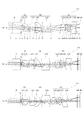
撮像素子50は、図1(a)に示すように、縦方向V(短方向)と横方向H(長方向)の長さの比が3:4の形状であり、V方向の端をV端と呼ぶ。V端という言葉は、V方向の端辺の全体を示す場合と、V方向の端辺の中点を示す場合があるが、以後の記述においては、後者の意味に用いる。図1(b)では、画面の4隅と上下V端の光線束を示している。このように、光学面の有効範囲は軸対称ではない。レンズは、軸対称に成型せずに、撮像素子50のV方向に相当する方向の上下をカットすることによって、上下方向の寸法を小さく抑えることができる。図1(b)に示すように、光線束の上下方向の限界は、画面の4隅と上下のV端で、ほとんど変わらないという性質があるので、レンズの上下方向の寸法は、V端の光線束の上下方向の光線高さで決まると考えて差し支えない。なお、撮像素子50のV方向とH方向の長さの比は、ハイディフィニション(High Definition)の場合9:16となる。すなわち、V:Hが3:4という比や9:16という比に限定されるものではない。
Hereinafter, embodiments of the present invention will be described in detail with reference to the drawings.
As shown in FIG. 1A, the
小型電子機器に内蔵する撮像光学系では、光学系の被写体方向の奥行きを小さくするため、被写体方向と撮像素子50のV方向を一致させる、すなわち、プリズムやミラーで光線束を90度折曲げることがある。被写体方向と撮像素子50のV方向を一致させた場合、光学系の被写体方向の奥行きを決めるのはV端に対応する光線束の中心軸に対する光線高さである。そこで、本発明は、V端の光線束の中心軸に対する光線高さを低く抑えることにより、撮像光学系の被写体方向の厚みを薄くすることを特徴とする。以下、この撮像光学系についてさらに詳しく述べる。
In an imaging optical system built in a small electronic device, in order to reduce the depth of the optical system in the subject direction, the subject direction and the V direction of the
本実施形態に係る撮像光学系は、倍率調整機能(ズーミング機能)を備えた光学系である。この撮像光学系は、被写体側の端部(前方)にプリズムやミラーなどの光軸折曲手段を備える。そして、撮像光学系は、光軸折曲手段の後方に、実像である中間像を生成する機能を有する正のパワーを有したレンズ群と、軸外光束を中心軸側(中心軸方向)に屈折させる機能を有する正のパワーを有したレンズ群と、中間像を撮像素子に結像させる機能を有する正のパワーを有したレンズ群と、を少なくとも備える。 The imaging optical system according to the present embodiment is an optical system having a magnification adjustment function (zooming function). This imaging optical system includes optical axis bending means such as a prism and a mirror at the end (front) on the subject side. Then, the imaging optical system has a positive power lens group having a function of generating a real intermediate image behind the optical axis bending means, and an off-axis light beam on the central axis side (central axial direction). A lens group having a positive power having a function of refracting, and a lens group having a positive power having a function of forming an intermediate image on the imaging element.
軸外光束を中心軸方向に屈折させる機能を有する正のパワーを有したレンズ群は、中間像が形成される位置の近傍に配置されている。すなわち、本実施形態に係る撮像光学系では、プリズムやミラーから射出された光線束の光線高さが高くなる前に中間像を形成し、さらに、この中間像が形成される位置の近傍で軸外光束を中心軸方向に屈折させることで、光学系全体での光線高さを低く抑えている。 A lens group having a positive power having a function of refracting the off-axis light beam in the central axis direction is disposed in the vicinity of the position where the intermediate image is formed. That is, in the imaging optical system according to the present embodiment, an intermediate image is formed before the light beam height of the light flux emitted from the prism or mirror increases, and an axis is formed near the position where the intermediate image is formed. By refracting the outer luminous flux in the central axis direction, the height of the light beam in the entire optical system is kept low.
また、本実施形態の撮像光学系は、中間像が生成されるため、絞りの中心を通る光線である主光線と中心軸(光軸)が中間像の前後の2箇所で交差する。よって、絞りは、前記中間像の前後の2箇所のいずれかの位置に配置されることとなる。 In the imaging optical system of the present embodiment, since an intermediate image is generated, the principal ray that is a light ray passing through the center of the stop and the central axis (optical axis) intersect at two places before and after the intermediate image. Therefore, the stop is arranged at one of two positions before and after the intermediate image.
このような構成の本実施形態における撮像光学系によれば、V端の光線高さを低く抑えることができる。一般に、すべての面における光線高さがV方向の画面サイズより等しいか小さければ、それ以上光学系を薄く(被写体方向の厚みを薄く)することができない。言い換えれば、その場合にはV方向の画面サイズで光学系の厚さが決まるため、光学系中でのV端の光線高さをそれ以上低くする必要はない。すなわち、V端の光線高さを低く抑えることができれば、V端の光線束を切らないようにレンズを切断することもでき、光学系全体を薄くすることが可能である。 According to the imaging optical system of the present embodiment having such a configuration, the height of the light beam at the V end can be kept low. In general, if the light beam height on all surfaces is equal to or smaller than the screen size in the V direction, the optical system cannot be further thinned (thickness in the subject direction). In other words, in this case, since the thickness of the optical system is determined by the screen size in the V direction, it is not necessary to further reduce the height of the light beam at the V end in the optical system. That is, if the height of the light beam at the V end can be kept low, the lens can be cut without cutting the light beam at the V end, and the entire optical system can be made thin.
このように、本実施形態における撮像光学系によれば、光軸折曲手段の前方に厚みのある凹レンズを配置したり、光軸折曲手段であるプリズムの前面に負のパワーを持たせたりすることなく、撮像光学系の薄型化を実現できる。すなわち、本実施形態によれば、厚みのある凹レンズや厚みの増した光軸折曲手段(プリズム)を用いることなく撮像光学系の薄型化や小型化を実現できるため、スペースに限りのある小型電子機器に容易に内蔵可能な撮像光学系を提供できることとなる。 Thus, according to the imaging optical system of the present embodiment, a thick concave lens is disposed in front of the optical axis bending means, or negative power is given to the front surface of the prism that is the optical axis bending means. Therefore, the imaging optical system can be made thinner. That is, according to the present embodiment, the imaging optical system can be thinned and miniaturized without using a thick concave lens or an optical axis bending means (prism) with an increased thickness. An imaging optical system that can be easily built in an electronic device can be provided.
また、本実施形態における撮像光学系は、上述したように、光線高さが高くなる前に中間像を形成し、且つ、軸外光束を中心軸方向に屈折させるため、V端の光線高さを低く抑えることができる。そして、V端の光線高さを低く抑えることにより、撮像光学系の薄型化を実現できる。 In addition, as described above, the imaging optical system according to the present embodiment forms an intermediate image before the light beam height increases and refracts the off-axis light beam in the central axis direction. Can be kept low. The imaging optical system can be thinned by suppressing the height of the light beam at the V end.
なお、レンズ群としているが、必ずしも複数のレンズで構成する必要はなく、上記各機能を実現できるのであれば各群を一枚のレンズで構成してもよい。また、上記3つの機能を実現する各レンズ群が倍率調整(ズーミング)用移動群として必ずしも独立したレンズ群である必要はなく、中間像を生成する機能と軸外の光線束を軸方向に屈折させる機能とを有した移動群など、一つのレンズ群に複数の機能を持たせてもよい。また、上記レンズ群の前方(被写体側)や後方(撮像素子側)に固定したレンズ群を配置してもよい。さらに、光軸折曲手段の前方に、フィルタや防護ガラスなど、厚みのわずかな光学部品を配置してもよい。なお、以下の説明では、被写体側を前方、撮像素子側を後方として述べる。 The lens group is not necessarily composed of a plurality of lenses, and each group may be composed of a single lens as long as the above functions can be realized. In addition, each lens group that realizes the above three functions does not necessarily need to be an independent lens group as a zooming movement group, and the function of generating an intermediate image and the off-axis light bundle are refracted in the axial direction. A plurality of functions may be given to one lens group, such as a moving group having a function of making it move. In addition, a lens group fixed in front of the lens group (subject side) or behind (imaging element side) may be disposed. Furthermore, an optical component having a small thickness such as a filter or a protective glass may be disposed in front of the optical axis bending means. In the following description, the subject side is referred to as the front and the image sensor side is referred to as the rear.
(第1の実施の形態)
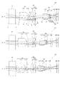
図2は、本発明の第1の実施の形態に係る撮像光学系1の近軸関係を示す図である。図2(a)は広角端(ワイド端)、(b)は中間倍率、(c)は望遠端(テレ端)を表している。なお、以下の図においては、近軸光線として、撮像素子50の中心(画面の中心)に投影される光線束と、一つのV端の光線束と、を表示している。
(First embodiment)
FIG. 2 is a diagram showing a paraxial relationship of the imaging
図2に示すように、第1の実施の形態に係る撮像光学系1は、前端に光軸折曲手段としてのプリズムPを備え、プリズムPの後方に絞りSと正のパワーを有した可動レンズ群とからなる第1群G1を備える。また、撮像光学系1は、第1群G1の後方に、正のパワーを有した可動レンズ群である第2群G2を備え、第2群G2の後方には正のパワーを有した可動レンズ群である第3群G3を備える。さらに撮像光学系1は、第3群G3の後方に赤外線フィルタIRFを備え、赤外線フィルタIRFの後方にCCDやCMOSなどの撮像素子50を備える。なお、図2においては、各群G1、G2、G3のレンズ群を一枚の薄肉レンズで模式して示しており、他の実施形態における図3〜図6に関しても同様である。これらの模式図は各群のパワーが正であること、中間像のおおまかな位置、各群が可動が固定か、および、各群の連動関係を示すためのものであり、各群のパワーの値や各群の位置に限定されるものではない。
As shown in FIG. 2, the imaging
プリズムPは、入射面から入射した光線束を90度折曲げて射出面から射出する光軸折曲手段である。図においては、光線束の進行状況を分かりやすくするためプリズムPは平面レンズとして記載しているが、実際は光線束を折曲げることが可能なプリズムである。なお、光軸折曲手段はプリズムに限定されずミラーなどを用いてもよい。光軸折曲手段がプリズムに限定されずミラーなどを用いてもよいことは、以下で記述する、第2から第5までの実施の形態においても同様である。 The prism P is an optical axis bending means that bends the light beam incident from the incident surface by 90 degrees and emits it from the exit surface. In the drawing, the prism P is described as a planar lens for easy understanding of the progress of the light beam, but in reality it is a prism that can bend the light beam. The optical axis bending means is not limited to a prism, and a mirror or the like may be used. The optical axis bending means is not limited to the prism, and a mirror or the like may be used in the second to fifth embodiments described below.
第1群G1は、プリズムPに近い側に絞りSが配置され、絞りSと正のパワーを有した可動レンズ群との間の距離は一定とされている。この第1群G1は、中間像IIを生成する機能を有しており、第1群G1の後方で中間像IIが生成される。 In the first group G1, the stop S is disposed on the side close to the prism P, and the distance between the stop S and the movable lens group having positive power is constant. The first group G1 has a function of generating the intermediate image II, and the intermediate image II is generated behind the first group G1.
第2群G2は、第1群G1で生成される中間像IIの近傍に配置されており、軸外光束を内側(中心軸O方向)に屈折させる機能を有している。また、第2群G2は、第1群G1で生成される中間像IIをリレーする機能を備えている。言い換えれば、第2群G2は、中間像IIをリレーする機能の一部を受け持っている。 The second group G2 is disposed in the vicinity of the intermediate image II generated in the first group G1, and has a function of refracting the off-axis light beam inward (in the direction of the central axis O). The second group G2 has a function of relaying the intermediate image II generated by the first group G1. In other words, the second group G2 is responsible for part of the function of relaying the intermediate image II.
第3群G3は、(第1群G1、第2群G2、第3群G3の中で)最も撮像素子50側に配置されており、第2群G2で屈折した光線束を撮像素子50に結像させる機能を有する。
The third group G3 is disposed closest to the image sensor 50 (among the first group G1, the second group G2, and the third group G3), and the light beam refracted by the second group G2 is applied to the
そして、本実施形態の撮像光学系1では、第1群G1、第2群G2、第3群G3の3つのレンズ群を軸に沿って動かしてズーミングを行い、第1群G1を軸に沿って動かしてフォーカシング(焦点調整)を行う。すなわち、本実施形態の撮像光学系1は、倍率調整機能と焦点調整機能を備えている。
In the imaging
次に、撮像光学系1における各群のパワー配分について述べる。撮像光学系1において全体の焦点距離は、中間像IIが一つあるため負になる。第2群G2は中間像付近に置かれるため、第2群G2による結像倍率は1程度になる。中間像IIと最終結像の大きさの比はワイド端で−1程度のため、第3群G3による結像倍率はワイド端で−1程度となる。全体の焦点距離は第1群G1の焦点距離と第2群G2による結像倍率と第3群G3による結像倍率の積のため、第1群G1の焦点距離はワイド端での全体の焦点距離と同程度の大きさとなる(逆符号)。
Next, power distribution of each group in the imaging
第2群G2の焦点距離は、第3群G3に対する入射瞳位置を決める働きを持ち、第3群G3に対する入射瞳位置から光学系全体の射出瞳位置が決まる。光学系全体の射出瞳位置は、撮像素子50への主光線の入射方向を左右する。そして、撮像素子50への主光線の入射方向には撮像素子50ごとに条件がある。その意味で第2群G2の焦点距離の範囲には広い可能性がある。また、非球面を多用する光学系では、画面周辺部での撮像素子50への主光線の入射方向が近軸射出瞳位置だけから一義的に決まるものではない。この面からも、第2群G2の焦点距離の範囲は広い可能性がある。
The focal length of the second group G2 serves to determine the entrance pupil position for the third group G3, and the exit pupil position of the entire optical system is determined from the entrance pupil position for the third group G3. The exit pupil position of the entire optical system determines the incident direction of the principal ray on the
第3群G3の焦点距離は、中間像IIから最終結像までの距離を決める機能を持つ。すなわち、第3群G3の焦点距離が長くなれば光学系全体の全長が長くなり、第3群G3の焦点距離が短くなれば光学系全体の全長が短くなる。光学系全体の全長は短い方が良いが、第3群G3の焦点距離が小さくなれば発生する収差量が増えるため、第3群G3の適当な焦点距離は、光学系の大きさと性能への要求のバランスから決まる。さらに第2群G2が中間像IIをリレーする機能の一部を受け持っているため、第3群G3の焦点距離には第2群G2の働きによる影響が生じる。 The focal length of the third group G3 has a function of determining the distance from the intermediate image II to the final image. That is, if the focal length of the third group G3 is increased, the entire length of the entire optical system is increased, and if the focal length of the third group G3 is decreased, the entire length of the entire optical system is decreased. Although the total length of the entire optical system is preferably short, the amount of aberration that occurs increases as the focal length of the third lens group G3 decreases. Therefore, the appropriate focal length of the third lens group G3 depends on the size and performance of the optical system. Determined from the balance of requirements. Furthermore, since the second group G2 is responsible for part of the function of relaying the intermediate image II, the focal length of the third group G3 is affected by the action of the second group G2.
以上の諸要素から各群のパワー配置は以下のように条件付けられる。表1の数値は、各群の焦点距離(FGi)/|ワイド端での全体の焦点距離(F)|で算出した数値である。ここで記号|は絶対値を意味する。 From the above factors, the power distribution of each group is conditioned as follows. The numerical values in Table 1 are the numerical values calculated by the focal length (FGi) / | total focal length (F) | at the wide end of each group. Here, the symbol | means an absolute value.
表1に示すように、第1群G1は、最小で0.5、最大で3.0とするのが好適である。第2群G2は、最小で0.5、最大ではINFINITY(無限)、すなわち、0.5以上とするのが好適である。第3群G3は、最小で0.5、最大で1.5とするのが好適である。なお、この表1の数値に限定されるわけではない。 As shown in Table 1, it is preferable that the first group G1 has a minimum value of 0.5 and a maximum value of 3.0. It is preferable that the second group G2 has a minimum value of 0.5 and a maximum value of INFINITY (infinite), that is, 0.5 or more. It is preferable that the third group G3 has a minimum value of 0.5 and a maximum value of 1.5. In addition, it is not necessarily limited to the numerical value of this Table 1.
(表1)
最小値 最大値
第1群G1 0.5 3.0
第2群G2 0.5 INFINITY
第3群G3 0.5 1.5
(Table 1)
Minimum value Maximum value 1st group G1 0.5 3.0
Second group G2 0.5 INFINITY
3rd group G3 0.5 1.5
本実施形態における撮像光学系1では、第1群G1で中間像を生成し、第2群G2で軸外光束を内側に屈折させるため、V端における光線高さを低く抑えることができる。すなわち、本実施形態によれば、V端における光線高さを低く抑えることができるため、被写体方向の厚みが薄い、薄型の撮像光学系1を提供できることとなる。
In the imaging
また、本実施形態における撮像光学系1では、3つのレンズ群をズーミングのために独立に動かす構成であるため、設計に対する自由度が高いという効果がある。
In addition, since the imaging
なお、本実施形態では、絞りSを第1群G1に配置しているが、この位置に限定されるものではない。上述したように、本発明では中間像IIを生成するため、絞りSを配置可能な場所は2箇所存在することとなる。よって、絞りSは、中間像IIの前方である第1群G1又はプリズムPの後面、或いは、中間像IIの後方である第3群G3に配置することができる。 In the present embodiment, the diaphragm S is arranged in the first group G1, but the position is not limited to this position. As described above, in the present invention, since the intermediate image II is generated, there are two places where the diaphragm S can be arranged. Therefore, the stop S can be disposed on the rear surface of the first group G1 or the prism P that is in front of the intermediate image II, or on the third group G3 that is behind the intermediate image II.
中間像IIの前方に絞りを配置する場合と、中間像IIの後方に絞りを配置する場合の、光学系にとっての主要な効果の違いは、絞り径を固定してズーミングを行なった場合のFNO(光学系の明るさ)の変動量の違いである。絞り径を固定してズーミングを行なった場合、ワイド端からテレ端に向けてFNOは徐々に大きく(つまり、光学系は暗く)なっていく。そして、中間像IIの後方に絞りを配置する場合の方が、中間像IIの前方に絞りを配置する場合よりも、一般的にFNOの変動量が小さい。どの程度のFNOの変動量が好ましいかは、それぞれの光学系の目的および用途に応じて決まる問題であり、それに従って、どの場所に絞りを配置するかが選ばれることになる。 The difference in the main effect for the optical system between the case where the stop is arranged in front of the intermediate image II and the case where the stop is arranged behind the intermediate image II is that the FNO when zooming is performed with the stop diameter fixed. This is a difference in fluctuation amount of (brightness of the optical system). When zooming is performed with the aperture diameter fixed, FNO gradually increases from the wide end to the tele end (that is, the optical system becomes darker). In general, the amount of variation in FNO is smaller when the stop is disposed behind the intermediate image II than when the stop is disposed in front of the intermediate image II. How much FNO variation is preferable is a problem that depends on the purpose and application of each optical system, and in accordance with this, the position at which the aperture is arranged is selected.
(第2の実施の形態)
図3は、本発明の第2の実施の形態における撮像光学系11の近軸関係を示す。図3(a)は広角端(ワイド端)、(b)は中間倍率、(c)は望遠端(テレ端)を表している。なお、上記第1の実施の形態と共通するものには同一の符号を付し、重複する説明は省略する。
(Second Embodiment)
FIG. 3 shows a paraxial relationship of the imaging
上記第1の実施の形態では、3つのレンズ群をズーミングのために独立に動かす構成としていたが、本実施形態では、3つのレンズ群のうちの1つのレンズ群をズーミングに使わずに固定することで変倍機構を簡素化したことを特徴としている。すなわち、本実施形態の撮像光学系11では、第1群G1をズーミングに使わずに、フォーカシングのためだけに移動させることを特徴としている。以下、本実施形態の撮像光学系11に関して詳しく述べる。
In the first embodiment, the three lens groups are independently moved for zooming. However, in this embodiment, one of the three lens groups is fixed without being used for zooming. It is characterized by simplifying the zoom mechanism. That is, the imaging
図3に示すように、本実施の形態における撮像光学系11は、前端に光軸折曲手段としてのプリズムPを備え、このプリズムPの後面に絞りSが形成されている。また、撮像光学系11は、プリズムPの後方に、正のパワーを有した可動レンズ群である第1群G1を備え、第1群G1の後方に、正のパワーを有した可動レンズ群である第2群G2、正のパワーを有した可動レンズ群である第3群G3を順に備える。さらに撮像光学系11は、第3群G3の後方に赤外線フィルタIRF及び撮像素子50を備える。
As shown in FIG. 3, the imaging
第1群G1は、第1の実施の形態と同様に中間像IIを生成する機能を有しており、第1群G1の後方で中間像IIが生成される。 The first group G1 has a function of generating the intermediate image II as in the first embodiment, and the intermediate image II is generated behind the first group G1.
第2群G2も第1の実施の形態と同様に、第1群G1で生成される中間像IIの近傍に配置されており、軸外光束を内側(軸方向)に屈折させる機能を有している。また、第2群G2は、第1群G1で生成される中間像IIをリレーする機能を備えている。言い換えれば、第2群G2は、中間像IIをリレーする機能の一部を受け持っている。 Similarly to the first embodiment, the second group G2 is also disposed in the vicinity of the intermediate image II generated by the first group G1, and has a function of refracting the off-axis light beam inward (in the axial direction). ing. The second group G2 has a function of relaying the intermediate image II generated by the first group G1. In other words, the second group G2 is responsible for part of the function of relaying the intermediate image II.
第3群G3も第1の実施の形態と同様に(第1群G1、第2群G2、第3群G3の中で)最も撮像素子50側に配置されており、第2群G2で屈折した光線束を撮像素子50に結像させる機能を有する。
The third group G3 is also arranged closest to the image sensor 50 (among the first group G1, the second group G2, and the third group G3) as in the first embodiment, and is refracted by the second group G2. The light beam bundle has a function of forming an image on the
そして、本実施形態の撮像光学系11では、第2群G2、第3群G3の2つのレンズ群を軸に沿って動かしてズーミングを行い、第1群G1を軸に沿って動かすことでフォーカシングを行う。すなわち、本実施形態の撮像光学系11は、倍率調整機能と焦点調整機能を備えており、第1群G1は、フォーカシング時のみ軸に沿って移動する。
In the imaging
次に、撮像光学系11における各群のパワー配分(各群の焦点距離(FGi)/|ワイド端での全体の焦点距離(F)|)について述べる。表2に示すように第1群G1は、最小で0.5、最大で3.0とするのが好適である。第2群G2は、最小で0.5、最大ではINFINITYとするのが好適である。第3群G3は、最小で0.5、最大で1.5とするのが好適である。なお、この表2の数値に限定されるわけではない。 Next, power distribution of each group in the imaging optical system 11 (focal length (FGi) of each group / | total focal length (F) | at the wide end) will be described. As shown in Table 2, it is preferable that the first group G1 has a minimum value of 0.5 and a maximum value of 3.0. The second group G2 is preferably 0.5 at the minimum and INFINITY at the maximum. It is preferable that the third group G3 has a minimum value of 0.5 and a maximum value of 1.5. The numerical values in Table 2 are not limited.
(表2)
最小値 最大値
第1群G1 0.5 3.0
第2群G2 0.5 INFINITY
第3群G3 0.5 1.5
(Table 2)
Minimum value Maximum value 1st group G1 0.5 3.0
Second group G2 0.5 INFINITY
3rd group G3 0.5 1.5
本実施形態における撮像光学系11では、第1群G1で中間像を生成し、第2群G2で軸外光束を内側に屈折させるため、V端の光線束の光線高さを低く抑えることができ、被写体方向の厚みが薄い、薄型の撮像光学系11を提供できることとなる。また、本実施形態の撮像光学系11は、フォーカシングがズーミングから分離されているのでフォーカシングの制御が単純化できるという利点がある。
In the imaging
なお、本実施形態では、絞りSをプリズムPの後面に配置しているが、この位置に限定されるものではない。上述したように、本発明では中間像IIを生成するため、絞りSを配置可能な場所は2箇所存在することとなる。よって、絞りSは、中間像IIの前方である第1群G1又はプリズムPの後面、或いは、中間像IIの後方である第3群G3に配置することができる。 In the present embodiment, the stop S is disposed on the rear surface of the prism P, but is not limited to this position. As described above, in the present invention, since the intermediate image II is generated, there are two places where the diaphragm S can be arranged. Therefore, the stop S can be disposed on the rear surface of the first group G1 or the prism P that is in front of the intermediate image II, or on the third group G3 that is behind the intermediate image II.
(第3の実施の形態)
図4は、本発明の第3の実施の形態における撮像光学系21の近軸関係を示す図である。図4(a)は広角端(ワイド端)、(b)は中間倍率、(c)は望遠端(テレ端)を表している。なお、上記他の実施の形態と共通するものには同一の符号を付し、重複する説明は省略する。本実施形態における撮像光学系21は、3つのレンズ群のうちの2つのレンズ群を連結して、一体として移動させることを特徴とする。すなわち、本実施形態では、第1群G1と第2群G2を連結していることを特徴とする。以下、本実施形態の撮像光学系21について詳しく述べる。
(Third embodiment)
FIG. 4 is a diagram showing a paraxial relationship of the imaging
図4に示すように、本実施の形態における撮像光学系21は、前端に光軸折曲手段としてのプリズムPを備える。また、撮像光学系21は、プリズムPの後方に、正のパワーを有した可動レンズ群である第1群G1及び第2群G2を備え、第2群G2の後方に正のパワーを有した可動レンズ群である第3群G3を備える。第1群G1と第2群G2は、間隔が固定されて前群GFを構成し、第3群G3は後群GRを構成している。さらに撮像光学系21は、第3群G3(後群GR)の後方に赤外線フィルタIRF及び撮像素子50を備える。
As shown in FIG. 4, the imaging
第1群G1は、上記第1及び第2の実施の形態と同様に中間像IIを生成する機能を有しており、第1群G1の後方で中間像IIが生成される。第2群G2も上記第1及び第2の実施の形態と同様に、第1群G1で生成される中間像IIの近傍に配置されており、軸外光束を内側(軸方向)に屈折させる機能を有している。第2群G2も上記他の実施形態と同様に、第1群で生成される中間像IIをリレーする機能を備えている。言い換えれば、第2群G2は、中間像IIをリレーする機能の一部を受け持っている。 The first group G1 has a function of generating the intermediate image II as in the first and second embodiments, and the intermediate image II is generated behind the first group G1. Similarly to the first and second embodiments, the second group G2 is also arranged in the vicinity of the intermediate image II generated by the first group G1, and refracts the off-axis light beam inward (in the axial direction). It has a function. Similarly to the other embodiments, the second group G2 also has a function of relaying the intermediate image II generated in the first group. In other words, the second group G2 is responsible for part of the function of relaying the intermediate image II.
第3群G3(後群GR)も上記他の実施の形態と同様に(第1群G1、第2群G2、第3群G3の中で)最も撮像素子50側に配置されており、第2群G2で屈折した光線束を撮像素子50に結像させる機能を有する。また、本実施形態では、第3群G3に絞りSが配置されている。
The third group G3 (rear group GR) is also arranged closest to the image sensor 50 (among the first group G1, the second group G2, and the third group G3) as in the other embodiments described above. The
すなわち、本実施の形態における撮像光学系21は、第1群G1と第2群G2により構成される前群GFと、第3群G3により構成される後群GRと、からなる。そして、前群GFが中間像を形成する機能、軸外光束を内側に屈折させる機能、および中間像IIをリレーする機能の一部を備えている。なお、前群GFを第1群G1と第2群G2とからなるとして説明したが、実際の光学系においては必ずしも第1群G1と第2群G2とをはっきりと区分けする必要はない。すなわち、中間像IIを生成する機能、及び、軸外光束を内側に屈折させる機能を有した前群GFと、中間像IIを撮像素子50に結像させる後群GRと、を備えていればよい。
That is, the imaging
そして、本実施形態の撮像光学系21では、第1群G1と第2群G2により構成される前群GFと、第3群G3である後群GRとを軸に沿って動かしてズーミングを行い、前群GFの全体を軸に沿って動かしてフォーカシングを行う。すなわち、本実施形態の撮像光学系21は、倍率調整機能と焦点調整機能を備えている。
In the imaging
次に、撮像光学系21における各群のパワー配分(各群の焦点距離(FGi)/|ワイド端での全体の焦点距離(F)|)について述べる。表3に示すように前群GFは、最小で0.5、最大で3.0とするのが好適である。後群GRは、最小で0.5、最大で1.5とするのが好適である。なお、この表3の数値に限定されるわけではない。 Next, power distribution of each group in the imaging optical system 21 (focal length (FGi) of each group / | total focal length (F) | at the wide end) will be described. As shown in Table 3, the front group GF is preferably set to 0.5 at the minimum and 3.0 at the maximum. The rear group GR is preferably set to a minimum of 0.5 and a maximum of 1.5. The numerical values in Table 3 are not limited.
(表3)
最小値 最大値
前群GF 0.5 3.0
後群GR 0.5 1.5
(Table 3)
Minimum value Maximum value Front group GF 0.5 3.0
Rear group GR 0.5 1.5
本実施形態における撮像光学系21では、前群GFで中間像を生成し、且つ、軸外光束を内側に屈折させるため、V端の光線束の光線高さを低く抑えることができ、被写体方向の厚みが薄い、薄型の撮像光学系21を提供できることとなる。また、この本実施形態の撮像光学系21は、前群GFと後群GRとにより構成されるため、移動群が2つなので機構が単純化できるという利点がある。
In the imaging
なお、本実施形態では、絞りSを第3群G3に配置しているが、この位置に限定されるものではない。上述したように、本発明では中間像IIを生成するため、絞りSを配置可能な場所は2箇所存在することとなる。よって、絞りSは、中間像IIの前方である第1群G1又はプリズムPの後面、或いは、中間像IIの後方である第3群G3に配置することができる。 In the present embodiment, the diaphragm S is disposed in the third group G3, but is not limited to this position. As described above, in the present invention, since the intermediate image II is generated, there are two places where the diaphragm S can be arranged. Therefore, the stop S can be disposed on the rear surface of the first group G1 or the prism P that is in front of the intermediate image II, or on the third group G3 that is behind the intermediate image II.
(第4の実施の形態)
図5は、本発明の第4の実施の形態における撮像光学系31の近軸関係を示す図である。図5(a)は広角端(ワイド端)、(b)は中間倍率、(c)は望遠端(テレ端)を表している。なお、上記他の実施の形態と共通するものには同一の符号を付し、重複する説明は省略する。本実施形態では第2群G2を固定してズーミングを行うことにより変倍機構を簡素化することを特徴とする。以下、本実施形態の撮像光学系31について詳しく述べる。
(Fourth embodiment)
FIG. 5 is a diagram showing a paraxial relationship of the imaging
図5に示すように、本実施の形態における撮像光学系31は、前端に光軸折曲手段としてのプリズムPを備える。また、撮像光学系31は、プリズムPの後方に、正のパワーを有した可動レンズ群である第1群G1を備え、第1群G1の後方に正のパワーを有した固定レンズ群である第2群G2を備え、第2群G2の後方に正のパワーを有した可動レンズ群である第3群G3を備える。さらに撮像光学系31は、第3群G3の後方に赤外線フィルタIRF及び撮像素子50を備える。
As shown in FIG. 5, the imaging
第1群G1は、上記他の実施の形態と同様に中間像IIを生成する機能を有しており、第1群G1の後方で中間像IIが生成される。 The first group G1 has a function of generating the intermediate image II as in the other embodiments described above, and the intermediate image II is generated behind the first group G1.
本実施形態における第2群G2は、固定されている。また、第2群G2は、上記他の実施の形態と同様に第1群G1で生成される中間像IIの近傍に配置されており、軸外光束を内側(軸方向)に屈折させる機能を有している。また、第2群G2は、第1群G1で生成される中間像IIをリレーする機能を備えている。言い換えれば、第2群G2は、中間像IIをリレーする機能の一部を受け持っている。 The second group G2 in the present embodiment is fixed. The second group G2 is arranged in the vicinity of the intermediate image II generated by the first group G1 as in the other embodiments, and has a function of refracting the off-axis light beam inward (in the axial direction). Have. The second group G2 has a function of relaying the intermediate image II generated by the first group G1. In other words, the second group G2 is responsible for part of the function of relaying the intermediate image II.
第3群G3も上記他の実施の形態と同様に(第1群G1、第2群G2、第3群G3の中で)最も撮像素子50側に配置されており、第2群G2で屈折した光線束を撮像素子50に結像させる機能を有する。また、本実施形態では、第3群G3に絞りSが配置されている。
The third group G3 is also arranged closest to the image sensor 50 (among the first group G1, the second group G2, and the third group G3), and is refracted by the second group G2, as in the other embodiments. The light beam bundle has a function of forming an image on the
そして、本実施形態の撮像光学系31では、第1群G1と第3群G3を軸に沿って動かしてズーミングを行い、第1群G1を軸に沿って動かしてフォーカシングを行う。すなわち、本実施形態の撮像光学系31は、倍率調整機能と焦点調整機能を備えている。
In the imaging
次に、撮像光学系31における各群のパワー配分(各群の焦点距離(FGi)/|ワイド端での全体の焦点距離(F)|)について述べる。表4に示すように第1群G1は、最小で0.5、最大で3.0とするのが好適である。第2群G2は、最小で0.5、最大ではINFINITYとするのが好適である。第3群G3は、最小で0.5、最大で1.5とするのが好適である。なお、この表4の数値に限定されるわけではない。 Next, power distribution of each group in the imaging optical system 31 (focal length (FGi) of each group / | total focal length (F) | at the wide end) will be described. As shown in Table 4, it is preferable that the first group G1 has a minimum value of 0.5 and a maximum value of 3.0. The second group G2 is preferably 0.5 at the minimum and INFINITY at the maximum. It is preferable that the third group G3 has a minimum value of 0.5 and a maximum value of 1.5. The numerical values in Table 4 are not limited.
(表4)
最小値 最大値
第1群G1 0.5 3.0
第2群G2 0.5 INFINITY
第3群G3 0.5 1.5
(Table 4)
Minimum value Maximum value 1st group G1 0.5 3.0
Second group G2 0.5 INFINITY
3rd group G3 0.5 1.5
本実施形態における撮像光学系31では、第1群G1で中間像IIを生成し、第2群G2で軸外光束を内側に屈折させるため、V端の光線束の光線高さを低く抑えることができ、被写体方向の厚みが薄い、薄型の撮像光学系31を提供できることとなる。また、この本実施形態の撮像光学系31は、移動群が2つなので機構を単純化できるという利点があり、また第2群G2が固定なので移動群の重量が少ないという利点がある。
In the imaging
なお、本実施形態では、絞りSを第3群G3に配置しているが、この位置に限定されるものではない。上述したように、本発明では中間像IIを生成するため、絞りSを配置可能な場所は2箇所存在することとなる。よって、絞りSは、中間像IIの前方である第1群G1又はプリズムPの後面、或いは、中間像IIの後方である第3群G3に配置することができる。 In the present embodiment, the diaphragm S is disposed in the third group G3, but is not limited to this position. As described above, in the present invention, since the intermediate image II is generated, there are two places where the diaphragm S can be arranged. Therefore, the stop S can be disposed on the rear surface of the first group G1 or the prism P that is in front of the intermediate image II, or on the third group G3 that is behind the intermediate image II.
(第5の実施の形態)
図6は、本発明の第5の実施の形態における撮像光学系41の近軸関係を示す図である。図6(a)は広角端(ワイド端)、(b)は中間倍率、(c)は望遠端(テレ端)を表している。なお、上記他の実施の形態と共通するものには同一の符号を付し、重複する説明は省略する。本実施形態における撮像光学系41は、第1群G1と第3群G3を連結してズーミングを行うことにより変倍機構を簡素化することを特徴とする。さらに、本実施形態の撮像光学系41では第2群G2を固定としていることも特徴とする。
(Fifth embodiment)
FIG. 6 is a diagram showing a paraxial relationship of the imaging
図6に示すように、本実施の形態における撮像光学系41は、前端に光軸折曲手段としてのプリズムPを備える。また、撮像光学系41は、プリズムPの後方に、正のパワーを有した可動レンズ群である第1群G1を備え、第1群G1の後方に正のパワーを有した固定レンズ群である第2群G2を備え、第2群G2の後方に正のパワーを有した可動レンズ群である第3群G3を備える。さらに撮像光学系41は、第3群G3の後方に赤外線フィルタIRF及び撮像素子50を備える。プリズムPの後面には、絞りSが配置されている。
As shown in FIG. 6, the imaging
第1群G1は、上記他の実施の形態と同様に中間像IIを生成する機能を有しており、第1群G1の後方で中間像IIが生成される。 The first group G1 has a function of generating the intermediate image II as in the other embodiments described above, and the intermediate image II is generated behind the first group G1.
本実施形態における第2群G2は固定されている。また、第2群G2は、上記他の実施の形態と同様に第1群G1で生成される中間像IIの近傍に配置されており、軸外光束を内側(軸方向)に屈折させる機能を有している。また、第2群G2は、第1群で生成される中間像IIをリレーする機能を備えている。言い換えれば、第2群G2は、中間像IIをリレーする機能の一部を受け持っている。 The second group G2 in this embodiment is fixed. The second group G2 is arranged in the vicinity of the intermediate image II generated by the first group G1 as in the other embodiments, and has a function of refracting the off-axis light beam inward (in the axial direction). Have. The second group G2 has a function of relaying the intermediate image II generated in the first group. In other words, the second group G2 is responsible for part of the function of relaying the intermediate image II.
第3群G3も上記各実施の形態と同様に(第1群G1、第2群G2、第3群G3の中で)最も撮像素子50側に配置されており、第2群G2で屈折した光線束を撮像素子50に結像させる機能を有する。
The third group G3 is also disposed closest to the image sensor 50 (among the first group G1, the second group G2, and the third group G3) and is refracted by the second group G2 as in the above embodiments. It has a function of forming an image of the light beam on the
そして、本実施形態の撮像光学系41では、第2群G2を固定し、第1群G1と第3群G3を連結してズーミングを行う。この場合は、最良像位置がズーミングに際してわずかに変動することになるが、EDoF(Extended Depth of Field)機能を用いることで鮮明な画像を得ることができる。EDoFは、被写界深度を広くする画像処理技術である。またEDoF機能を用いるのでフォーカシングのための移動群は必要ない。
In the imaging
次に、撮像光学系41における各群のパワー配分(各群の焦点距離(FGi)/|ワイド端での全体の焦点距離(F)|)について述べる。表5に示すように第1群G1は、最小で0.5、最大で3.0とするのが好適である。第2群G2は、最小で0.5、最大ではINFINITYとするのが好適である。第3群G3は、最小で0.5、最大で1.5とするのが好適である。なお、この表5の数値に限定されるわけではない。 Next, power distribution of each group in the imaging optical system 41 (focal length (FGi) / | total focal length (F) | at the wide end) of each group will be described. As shown in Table 5, it is preferable that the first group G1 has a minimum value of 0.5 and a maximum value of 3.0. The second group G2 is preferably 0.5 at the minimum and INFINITY at the maximum. It is preferable that the third group G3 has a minimum value of 0.5 and a maximum value of 1.5. Note that the values are not limited to those in Table 5.
(表5)
最小値 最大値
第1群G1 0.5 3.0
第2群G2 0.5 INFINITY
第3群G3 0.5 1.5
(Table 5)
Minimum value Maximum value 1st group G1 0.5 3.0
Second group G2 0.5 INFINITY
3rd group G3 0.5 1.5
本実施形態における撮像光学系41では、第1群G1で中間像IIを生成し、第2群G2で軸外光束を内側に屈折させるため、被写体方向の厚みが薄い、薄型の撮像光学系41を提供できることとなる。また、この本実施形態の撮像光学系41は、第2群G2を固定にし、第1群G1と第3群G3を連結して動かすため可動部の制御が容易となる。
In the imaging
なお、本実施形態では、絞りSをプリズムPの後面に配置しているが、この位置に限定されるものではない。上述したように、本発明では中間像IIを生成するため、絞りSを配置可能な場所は2箇所存在することとなる。よって、絞りSは、中間像IIの前方である第1群G1又はプリズムPの後面、或いは、中間像IIの後方である第3群G3に配置することができる。 In the present embodiment, the stop S is disposed on the rear surface of the prism P, but is not limited to this position. As described above, in the present invention, since the intermediate image II is generated, there are two places where the diaphragm S can be arranged. Therefore, the stop S can be disposed on the rear surface of the first group G1 or the prism P that is in front of the intermediate image II, or on the third group G3 that is behind the intermediate image II.
(全実施の形態に共通)
以上、5つの実施の形態を記述した。変倍機構の簡素化の一つの方法は、1つの群を固定することであり、第2の実施の形態では第1群G1を固定し、第4の実施の形態では第2群G2を固定している。変倍機構の簡素化のもう一つの方法は、2つの群を連結することであり、第3の実施の形態では第1群G1と第2群G2を連結し、第5の実施の形態では第1群G1と第3群G3を連結している。
(Common to all embodiments)
In the above, five embodiments have been described. One method of simplifying the zooming mechanism is to fix one group. In the second embodiment, the first group G1 is fixed, and in the fourth embodiment, the second group G2 is fixed. doing. Another method of simplifying the zooming mechanism is to connect two groups. In the third embodiment, the first group G1 and the second group G2 are connected, and in the fifth embodiment, The first group G1 and the third group G3 are connected.
変倍機構の簡素化の残る可能性として、第3群G3を固定する場合と、第2群G2と第3群G3を連結する場合が考えられる。しかし、第3群G3を固定することは、第3群G3がバリエータとして機能していることから不適当であり、また第2群G2と第3群G3を連結することは、V端の光線束の光線高さを低く抑えることを難しくするため不適当である。さらに、第5の実施の形態に関連して、第2群G2をズーミングのために動かし、EDoF機能を用いない実施の形態があり得るが、そのような実施の形態が成立することは、第5の実施の形態より明らかである。 As the possibility of the simplification of the zooming mechanism remaining, there are a case where the third group G3 is fixed and a case where the second group G2 and the third group G3 are connected. However, fixing the third group G3 is inappropriate because the third group G3 functions as a variator, and connecting the second group G2 and the third group G3 is not possible with the V-end beam. This is inappropriate because it makes it difficult to keep the beam height of the bundle low. Further, in relation to the fifth embodiment, there may be an embodiment in which the second group G2 is moved for zooming and the EDoF function is not used. This is clear from the fifth embodiment.
一方、変倍機構の簡素化とは逆に、以上で記述した5つの実施の形態におけるレンズ群の一部または全部を、さらに複数のレンズ群に分割して、変倍機構として独立に移動させることが考えられる。これによって、コストや重量の上昇などと引き換えに、結像性能を向上させることが可能である。しかし、レンズ群の分割により派生する、そのような複雑化した変倍機構は、以上で記述した5つの実施の形態の範囲に含まれるものである。 On the other hand, contrary to simplification of the zooming mechanism, part or all of the lens groups in the five embodiments described above are further divided into a plurality of lens groups and moved independently as a zooming mechanism. It is possible. As a result, it is possible to improve imaging performance in exchange for an increase in cost and weight. However, such a complicated zooming mechanism derived from the division of the lens group is included in the scope of the five embodiments described above.
以下、上記第1〜第5の実施の形態で述べた撮像光学系1、11、21、31、41の具体的なレンズ構成について述べる。以下の実施例におけるレンズ構成は、被写体方向の厚みが薄い、薄型の撮像光学系を実現するために、上記第1から第5までの実施の形態が有効であることを示す実例であるが、実施例以外にも多くのレンズ構成があり得るため、以下の実施例に限定されるものではない。
Hereinafter, specific lens configurations of the imaging
(実施例1)
図7は、撮像光学系101の断面図である。この断面図における各レンズの有効径は、最大像高の光束に対応するものである。また、撮像素子50の中心(画面の中心)に投影される光線束と、一つのV端の光線束と、を表示している。撮像光学系101は、上記第1の実施の形態で述べた撮像光学系1の実施例である。
Example 1
FIG. 7 is a cross-sectional view of the imaging
図7に示すように本実施例の撮像光学系101は、プリズムPの後方に順に正のパワーを有する可動レンズ群である第1群G1、第2群G2、第3群G3を備える。また、第3群G3の後面には、固定レンズL41が配置され、固定レンズL41の後面に赤外線フィルタIRF、撮像素子50が順に配置されている。プリズムPの後面には絞りSが形成されている。
As shown in FIG. 7, the imaging
第1群G1は、両凸レンズである第1レンズL11と、前面を凹、後面を凸としたメニスカスレンズである第2レンズL12と、の貼り合わせレンズで構成される。 The first group G1 includes a cemented lens of a first lens L11 that is a biconvex lens and a second lens L12 that is a meniscus lens having a concave front surface and a convex rear surface.
第2群G2は、前面が凹、後面が凸のメニスカスレンズである第3レンズL21と、前面が凸、後面が凹のメニスカスレンズである第4レンズL22と、両凸レンズである第5レンズL23と、から構成される。 The second group G2 includes a third lens L21 that is a meniscus lens having a concave front surface and a convex rear surface, a fourth lens L22 that is a meniscus lens having a convex front surface and a concave rear surface, and a fifth lens L23 that is a biconvex lens. And.
第3群G3は、前面が凹、後面が凸のメニスカスレンズである第6レンズL31と、前面が凸、後面が凹のメニスカスレンズである第7レンズL32と、前面が凸、後面が凹のメニスカスレンズである第8レンズL33と、から構成される。 The third group G3 includes a sixth lens L31 that is a meniscus lens having a concave front surface and a convex rear surface, a seventh lens L32 that is a meniscus lens having a convex front surface and a concave rear surface, and a convex front surface and a concave rear surface. And an eighth lens L33 which is a meniscus lens.
固定レンズL41は、前面が凸、後方が凹のメニスカスレンズである。なお、第1群G1〜第3群G3、及び、固定レンズL41における全てのレンズは接合面4を除いて非球面レンズである。
The fixed lens L41 is a meniscus lens having a convex front surface and a concave rear surface. All lenses in the first group G1 to the third group G3 and the fixed lens L41 are aspherical lenses except for the cemented
本実施例の撮像光学系101は、第1群G1、第2群G2、第3群G3を夫々移動させてズーミングを行い、第1群G1を動かしてフォーカシングを行う。
The imaging
以下の表6に図7に示した撮像光学系101の諸元を示す。この表6において、全体諸元に示すωはワイド端における半画角を示し、FNOは焦点距離を入射瞳径で割った(焦点距離/入射瞳径)数値であり光学系の明るさを表す。実施例の光学系では、絞り径はズーミングに際して固定であり、そのため、FNOはズーミングとともに変動する。表におけるFNOはワイド端における値である。Fは、レンズ全体のワイド端での焦点距離を表し、Yは、最大像高を表す。なお、ワイド端での全体の焦点距離Fは、本発明では中間像を形成するため符号は−(負)となる。Lは、撮像光学系101の全長(プリズムPを反射面で展開した状態でプリズム前面から像面までの距離)を表わす。また、レンズデータにおけるmは、被写体側(前端)からの各光学面の番号(面番号)を示し(図7(a)の数字に対応)、rは各光学面の曲率半径を示し、dは各光学面から次の光学面までの光軸上の距離(面間隔)を示す。さらに、ndはd線(λ=587.6nm)に対する屈折率を示し、νdはd線に対するアッベ数を示している。また、FGi/|F|は、各群の焦点距離(FGi)/|ワイド端での全体の焦点距離(F)|を示す。さらに、非球面係数の定義は(1)式で表される。
Table 6 below shows specifications of the imaging

ただし、z:高さhの位置でのz軸方向の変位量(面頂点基準)
h:z軸に対して垂直な方向の高さ(h2=x2+y2)
c:近軸曲率(=1/曲率半径)
A、B、C、D、E、F:
それぞれ4、6、8、10、12、14次の非球面係数
K: 円錐係数
である。また、群間隔におけるWはワイド端、Mは中間倍率、Tはテレ端を表す。
Where z is the amount of displacement in the z-axis direction at the height h (based on the surface vertex)
h: Height in the direction perpendicular to the z-axis (h 2 = x 2 + y 2 )
c: Paraxial curvature (= 1 / radius of curvature)
A, B, C, D, E, F:
4th, 6th, 8th, 10th, 12th and 14th order aspheric coefficients
K: Conic coefficient. In the group interval, W represents the wide end, M represents the intermediate magnification, and T represents the tele end.
(表6)
全体諸元
2ω=70°
画面サイズ=4.552mm×3.414mm (Y=2.845mm)
FNO=2.4
ズーム比=2.8倍
F=−4.063mm
L=26.92mm
V端光束の最大光束幅=3.4mm
レンズデータ
m r d nd νd
1 INFINITY 3.4000000 1.51680 64.20
2 INFINITY 0.6017373
3 3.3566724 1.4381623 1.49700 81.61
4 -4.0098956 2.6325521 1.64769 33.84
5 -7.4836021 0.2125802
6 -6.0333656 1.3220721 1.59201 67.02
7 -1.6671657 0.1374810
8 3.2767314 1.4596985 1.84666 23.78
9 0.8197137 0.5179634
10 1.6177176 2.2719648 1.63854 55.45
11 -4.8328802 5.1742651
12 -18.0491558 1.1384586 1.49700 81.61
13 -1.7777505 0.0999860
14 1.4688631 0.8122264 1.56907 71.30
15 1.8766719 0.1363150
16 4.9994891 0.4999910 1.84666 23.78
17 1.6428635 1.6954327
18 3.7928310 1.8395681 1.72916 54.67
19 3.3606612 0.3270049
20 INFINITY 0.3000000 1.51680 64.20
21 INFINITY 0.8998775
非球面係数
m K A B C D E F
3 -8.02E+00 2.77E-02 -1.15E-02 6.62E-03 -2.61E-03 5.66E-04 -5.17E-05
5 -1.80E+01 -9.66E-04 3.89E-04 4.52E-04 -1.37E-04 1.81E-05 -7.92E-07
6 5.21E-01 5.71E-02 -7.87E-03 2.44E-04 4.42E-05 -3.31E-06 -4.02E-08
7 -3.40E+00 6.48E-02 -6.52E-03 -2.66E-03 7.10E-04 -6.39E-05 1.97E-06
8 -4.73E-01 -1.11E-02 5.10E-03 -4.50E-03 1.04E-03 -1.01E-04 3.68E-06
9 -3.85E+00 2.42E-03 -1.08E-02 2.89E-03 -3.56E-04 2.25E-05 -5.78E-07
10 -6.48E+00 8.83E-03 -5.50E-03 9.69E-04 -8.63E-05 4.09E-06 -8.78E-08
11 -9.32E-01 1.45E-03 2.38E-04 -1.35E-04 1.36E-05 -7.88E-07 1.23E-08
12 -6.98E-01 2.81E-02 -1.63E-02 7.35E-03 -1.84E-03 2.28E-04 -1.31E-05
13 -3.38E+00 -3.64E-03 3.21E-03 -6.07E-04 1.13E-05 -1.73E-06 -7.39E-07
14 -2.95E-01 -3.62E-02 -3.80E-02 3.64E-02 -2.33E-02 6.23E-03 -7.34E-04
15 6.49E-01 -2.21E-01 3.41E-02 1.39E-02 -1.74E-02 5.63E-03 -1.28E-03
16 9.05E+00 2.01E-01 -2.14E-01 1.65E-01 -8.65E-02 2.67E-02 -3.70E-03
17 1.17E+00 2.93E-01 -1.63E-01 -4.55E-02 4.94E-01 -8.43E-01 3.77E-01
18 -1.24E+00 -2.22E-02 -2.67E-03 3.45E-03 -8.64E-04 8.84E-05 -3.23E-06
19 -3.83E+00 -2.05E-02 -2.06E-03 1.67E-03 -3.03E-04 2.20E-05 -5.57E-07
群間隔
m W M T
2 0.6017373 0.5707610 1.6660788
5 0.2125802 2.7359933 3.5105097
11 5.1742651 2.2874673 0.2068006
17 1.6954327 2.0895333 2.3004180
FGi/|F|
i=1(第1群) i=2(第2群) i=3(第3群)
1.3975 1.0297 0.8025
(Table 6)
Overall specifications 2ω = 70 °
Screen size = 4.552 mm × 3.414 mm (Y = 2.845 mm)
FNO = 2.4
Zoom ratio = 2.8x F = -4.063mm
L = 26.92mm
Maximum beam width of V-end beam = 3.4mm
Lens data
mrd nd νd
1 INFINITY 3.4000000 1.51680 64.20
2 INFINITY 0.6017373
3 3.3566724 1.4381623 1.49700 81.61
4 -4.0098956 2.6325521 1.64769 33.84
5 -7.4836021 0.2125802
6 -6.0333656 1.3220721 1.59201 67.02
7 -1.6671657 0.1374810
8 3.2767314 1.4596985 1.84666 23.78
9 0.8197137 0.5179634
10 1.6177176 2.2719648 1.63854 55.45
11 -4.8328802 5.1742651
12 -18.0491558 1.1384586 1.49700 81.61
13 -1.7777505 0.0999860
14 1.4688631 0.8122264 1.56907 71.30
15 1.8766719 0.1363150
16 4.9994891 0.4999910 1.84666 23.78
17 1.6428635 1.6954327
18 3.7928310 1.8395681 1.72916 54.67
19 3.3606612 0.3270049
20 INFINITY 0.3000000 1.51680 64.20
21 INFINITY 0.8998775
Aspheric coefficient
m KABCDEF
3 -8.02E + 00 2.77E-02 -1.15E-02 6.62E-03 -2.61E-03 5.66E-04 -5.17E-05
5 -1.80E + 01 -9.66E-04 3.89E-04 4.52E-04 -1.37E-04 1.81E-05 -7.92E-07
6 5.21E-01 5.71E-02 -7.87E-03 2.44E-04 4.42E-05 -3.31E-06 -4.02E-08
7 -3.40E + 00 6.48E-02 -6.52E-03 -2.66E-03 7.10E-04 -6.39E-05 1.97E-06
8 -4.73E-01 -1.11E-02 5.10E-03 -4.50E-03 1.04E-03 -1.01E-04 3.68E-06
9 -3.85E + 00 2.42E-03 -1.08E-02 2.89E-03 -3.56E-04 2.25E-05 -5.78E-07
10 -6.48E + 00 8.83E-03 -5.50E-03 9.69E-04 -8.63E-05 4.09E-06 -8.78E-08
11 -9.32E-01 1.45E-03 2.38E-04 -1.35E-04 1.36E-05 -7.88E-07 1.23E-08
12 -6.98E-01 2.81E-02 -1.63E-02 7.35E-03 -1.84E-03 2.28E-04 -1.31E-05
13 -3.38E + 00 -3.64E-03 3.21E-03 -6.07E-04 1.13E-05 -1.73E-06 -7.39E-07
14 -2.95E-01 -3.62E-02 -3.80E-02 3.64E-02 -2.33E-02 6.23E-03 -7.34E-04
15 6.49E-01 -2.21E-01 3.41E-02 1.39E-02 -1.74E-02 5.63E-03 -1.28E-03
16 9.05E + 00 2.01E-01 -2.14E-01 1.65E-01 -8.65E-02 2.67E-02 -3.70E-03
17 1.17E + 00 2.93E-01 -1.63E-01 -4.55E-02 4.94E-01 -8.43E-01 3.77E-01
18 -1.24E + 00 -2.22E-02 -2.67E-03 3.45E-03 -8.64E-04 8.84E-05 -3.23E-06
19 -3.83E + 00 -2.05E-02 -2.06E-03 1.67E-03 -3.03E-04 2.20E-05 -5.57E-07
Group spacing
m WMT
2 0.6017373 0.5707610 1.6660788
5 0.2125802 2.7359933 3.5105097
11 5.1742651 2.2874673 0.2068006
17 1.6954327 2.0895333 2.3004180
FGi / | F |
i = 1 (first group) i = 2 (second group) i = 3 (third group)
1.3975 1.0297 0.8025
本実施例における、各群の焦点距離(FGi)/|ワイド端での全体の焦点距離(F)|の数値は、表1に示した条件を満たしていることが分かる。また、V端光束の最大光束幅が3.4mmであるため、画面サイズのV方向の数値である3.414mmと略同一の数値を実現している。よって、被写体方向の厚みが薄い、薄型の撮像光学系を実現できている。さらに、レンズ全長Lが、26.92mmと短いため、撮像光学系の配置スペースに限りのある小型電子機器に容易に内蔵可能な小型の撮像光学系を提供できる。 It can be seen that the numerical values of the focal length (FGi) / | total focal length (F) | at the wide end in the present example satisfy the conditions shown in Table 1. Further, since the maximum luminous flux width of the V-end luminous flux is 3.4 mm, a numerical value substantially the same as 3.414 mm which is a numerical value in the V direction of the screen size is realized. Therefore, a thin imaging optical system having a small thickness in the subject direction can be realized. Furthermore, since the total lens length L is as short as 26.92 mm, it is possible to provide a small imaging optical system that can be easily incorporated in a small electronic device having a limited space for the imaging optical system.
(実施例2)
図8は、本実施例の撮像光学系111の断面図である。撮像光学系111は、上記第2の実施の形態で述べた撮像光学系11の実施例である。図8に示すように本実施例の撮像光学系111は、プリズムPの後方に正のパワーを有するレンズ群である第1群G1を備え、第1群G1の後方に正のパワーを有する可動レンズ群である第2群G2、第3群G3を備える。また、第3群G3の後方には、赤外線フィルタIRF、撮像素子50が順に配置されている。絞りSは、プリズムPの後方であって第1群G1の前端(被写体側)に配置されている。
(Example 2)
FIG. 8 is a cross-sectional view of the imaging
第1群G1は、両凸レンズである第1レンズL11と、前面を凹、後面を凸としたメニスカスレンズである第2レンズL12と、の貼り合わせレンズで構成される。 The first group G1 includes a cemented lens of a first lens L11 that is a biconvex lens and a second lens L12 that is a meniscus lens having a concave front surface and a convex rear surface.
第2群G2は、両凸レンズである第3レンズL21と、前面が凹、後面が凸のメニスカスレンズである第4レンズL22と、前面が凹、後面が凸のメニスカスレンズである第5レンズL23と、から構成される。 The second group G2 includes a third lens L21 which is a biconvex lens, a fourth lens L22 which is a meniscus lens having a concave front surface and a convex rear surface, and a fifth lens L23 which is a meniscus lens having a concave front surface and a convex rear surface. And.
第3群G3は、両凸レンズである第6レンズL31と、前面が凸、後面が凹のメニスカスレンズである第7レンズL32と、を備える。さらに、第3群G3は、第7レンズL32の後方に、前面が凹、後面が凸のメニスカスレンズである第8レンズL33と、前面が凸、後面が凹のメニスカスレンズである第9レンズL34と、を備える。なお、第1群G1〜第3群G3における全てのレンズは接合面5を除いて非球面レンズである。
The third group G3 includes a sixth lens L31 that is a biconvex lens and a seventh lens L32 that is a meniscus lens having a convex front surface and a concave rear surface. Further, the third group G3 includes an eighth lens L33, which is a meniscus lens having a concave front surface and a convex rear surface, and a ninth lens L34 which is a meniscus lens having a convex front surface and a concave rear surface, behind the seventh lens L32. And comprising. All the lenses in the first group G1 to the third group G3 are aspherical lenses except for the cemented
本実施例の撮像光学系111は、第2群G2と第3群G3でズーミングを行い、第1群G1でフォーカシングを行う。
The imaging
以下の表7に図8に示した撮像光学系111の諸元を示す。
Table 7 below shows the specifications of the imaging
(表7)
全体諸元
2ω=70°
画面サイズ=4.552mm×3.414mm (Y=2.845mm)
FNO=2.8
ズーム比=2.8倍
F=−4.063mm
L=29.51mm
V端光束の最大光束幅=3.6mm
レンズデータ
m r d nd νd
1 INFINITY 3.6000000 1.51680 64.20
2 INFINITY 0.3305860
3 INFINITY 0.0999981
4 4.7924242 1.1967433 1.49700 81.61
5 -1.0139650 1.7822256 1.56883 56.04
6 -2.0859000 0.6455099
7 22.0437595 2.3410094 1.84666 23.78
8 -8.9968220 1.0534341
9 -0.9485915 1.5898679 1.69680 55.46
10 -1.3216959 0.3701573
11 -5.5587778 3.7374191 1.71300 53.94
12 -8.3626145 4.2411460
13 2.7923560 2.1533553 1.49700 81.61
14 -2.0953558 0.1026413
15 3.5431426 0.5000100 1.70154 41.15
16 1.7026495 0.9547510
17 -0.8004187 0.5014478 1.84666 23.78
18 -1.6741317 0.1064285
19 1.3261020 2.1648015 1.71300 53.94
20 1.8840294 0.8440608
21 INFINITY 0.3000000 1.51680 64.20
22 INFINITY 0.8992454
非球面係数
m K A B C D E F
4 5.86E+00 -1.59E-02 2.33E-02 -4.54E-02 3.87E-02 4.66E-03 -5.08E-03
6 -4.37E+00 -5.46E-02 2.46E-02 -1.17E-02 3.39E-03 -5.29E-04 3.46E-05
7 2.33E+00 -2.75E-03 6.95E-03 -3.62E-03 1.16E-03 -1.87E-04 1.11E-05
8 4.92E+00 -1.13E-02 -3.32E-03 1.47E-03 1.55E-04 2.68E-05 9.25E-07
9 -6.25E+00 -1.60E-01 3.50E-02 6.39E-03 -3.40E-03 4.85E-04 -2.49E-05
10 -7.42E-01 4.56E-02 -1.43E-02 4.75E-03 -5.13E-04 1.99E-05 -6.77E-07
11 -4.96E+00 5.29E-02 -9.21E-03 5.97E-04 4.20E-05 -7.27E-06 2.25E-07
12 3.22E-01 -2.41E-03 1.38E-03 -3.86E-04 5.96E-05 -4.22E-06 1.48E-07
13 7.71E-01 -9.56E-03 -3.66E-03 -4.60E-04 -1.74E-04 -3.24E-05 -1.32E-06
14 -5.61E+00 -2.38E-02 2.09E-03 9.00E-06 -5.99E-04 1.92E-04 -1.78E-05
15 3.23E+00 -1.02E-01 -1.47E-03 -3.23E-03 6.35E-03 -2.22E-03 2.09E-04
16 -3.21E-01 -1.74E-01 2.72E-02 -2.11E-02 1.21E-02 -3.18E-03 3.19E-04
17 -4.03E+00 -2.20E-02 8.19E-02 -8.15E-02 3.86E-02 -9.28E-03 8.87E-04
18 -5.26E+00 -2.75E-02 4.79E-02 -1.96E-02 7.19E-03 -1.60E-03 1.16E-04
19 -5.80E+00 2.64E-05 -2.21E-03 -7.48E-04 5.03E-04 -8.98E-05 4.32E-06
20 -4.56E+00 1.08E-03 -1.99E-03 2.98E-04 -4.02E-05 1.87E-06 -1.25E-08
群間隔
m W M T
6 0.6455099 0.2657847 0.5489867
12 4.2411460 2.1822547 0.5402629
20 0.8440608 3.2828722 4.6416292
FGi/|F|
i=1 i=2 i=3
0.8871 1.8302 0.8760
(Table 7)
Overall specifications 2ω = 70 °
Screen size = 4.552 mm × 3.414 mm (Y = 2.845 mm)
FNO = 2.8
Zoom ratio = 2.8 times F = −4.063 mm
L = 29.51mm
Maximum beam width of V-end beam = 3.6 mm
Lens data
mrd nd νd
1 INFINITY 3.6000000 1.51680 64.20
2 INFINITY 0.3305860
3 INFINITY 0.0999981
4 4.7924242 1.1967433 1.49700 81.61
5 -1.0139650 1.7822256 1.56883 56.04
6 -2.0859000 0.6455099
7 22.0437595 2.3410094 1.84666 23.78
8 -8.9968220 1.0534341
9 -0.9485915 1.5898679 1.69680 55.46
10 -1.3216959 0.3701573
11 -5.5587778 3.7374191 1.71300 53.94
12 -8.3626145 4.2411460
13 2.7923560 2.1533553 1.49700 81.61
14 -2.0953558 0.1026413
15 3.5431426 0.5000100 1.70154 41.15
16 1.7026495 0.9547510
17 -0.8004187 0.5014478 1.84666 23.78
18 -1.6741317 0.1064285
19 1.3261020 2.1648015 1.71300 53.94
20 1.8840294 0.8440608
21 INFINITY 0.3000000 1.51680 64.20
22 INFINITY 0.8992454
Aspheric coefficient
m KABCDEF
4 5.86E + 00 -1.59E-02 2.33E-02 -4.54E-02 3.87E-02 4.66E-03 -5.08E-03
6 -4.37E + 00 -5.46E-02 2.46E-02 -1.17E-02 3.39E-03 -5.29E-04 3.46E-05
7 2.33E + 00 -2.75E-03 6.95E-03 -3.62E-03 1.16E-03 -1.87E-04 1.11E-05
8 4.92E + 00 -1.13E-02 -3.32E-03 1.47E-03 1.55E-04 2.68E-05 9.25E-07
9 -6.25E + 00 -1.60E-01 3.50E-02 6.39E-03 -3.40E-03 4.85E-04 -2.49E-05
10 -7.42E-01 4.56E-02 -1.43E-02 4.75E-03 -5.13E-04 1.99E-05 -6.77E-07
11 -4.96E + 00 5.29E-02 -9.21E-03 5.97E-04 4.20E-05 -7.27E-06 2.25E-07
12 3.22E-01 -2.41E-03 1.38E-03 -3.86E-04 5.96E-05 -4.22E-06 1.48E-07
13 7.71E-01 -9.56E-03 -3.66E-03 -4.60E-04 -1.74E-04 -3.24E-05 -1.32E-06
14 -5.61E + 00 -2.38E-02 2.09E-03 9.00E-06 -5.99E-04 1.92E-04 -1.78E-05
15 3.23E + 00 -1.02E-01 -1.47E-03 -3.23E-03 6.35E-03 -2.22E-03 2.09E-04
16 -3.21E-01 -1.74E-01 2.72E-02 -2.11E-02 1.21E-02 -3.18E-03 3.19E-04
17 -4.03E + 00 -2.20E-02 8.19E-02 -8.15E-02 3.86E-02 -9.28E-03 8.87E-04
18 -5.26E + 00 -2.75E-02 4.79E-02 -1.96E-02 7.19E-03 -1.60E-03 1.16E-04
19 -5.80E + 00 2.64E-05 -2.21E-03 -7.48E-04 5.03E-04 -8.98E-05 4.32E-06
20 -4.56E + 00 1.08E-03 -1.99E-03 2.98E-04 -4.02E-05 1.87E-06 -1.25E-08
Group spacing
m WMT
6 0.6455099 0.2657847 0.5489867
12 4.2411460 2.1822547 0.5402629
20 0.8440608 3.2828722 4.6416292
FGi / | F |
i = 1 i = 2 i = 3
0.8871 1.8302 0.8760
本実施例における、各群の焦点距離(FGi)/|ワイド端での全体の焦点距離(F)|の数値は、表2に示した条件を満たしていることが分かる。また、V端光束の最大光束幅が3.6mmであり、画面サイズのV方向の数値である3.414mmに近い数値であるため、被写体方向の厚みが薄い、薄型の撮像光学系が実現している。さらに、レンズ全長Lが、29.51mmと短いため、撮像光学系の配置スペースに限りのある小型電子機器に容易に内蔵可能な小型の撮像光学系を提供できることが分かる。 It can be seen that the numerical values of the focal length (FGi) / | total focal length (F) | at the wide end in the present example satisfy the conditions shown in Table 2. In addition, since the maximum beam width of the V-end beam is 3.6 mm, which is close to the value of 3.414 mm in the V direction of the screen size, a thin imaging optical system with a thin thickness in the subject direction is realized. ing. Furthermore, since the total lens length L is as short as 29.51 mm, it can be seen that it is possible to provide a small imaging optical system that can be easily incorporated in a small electronic device having a limited space for the imaging optical system.
(実施例3)
図9は、本実施例の撮像光学系121の断面図である。撮像光学系121は、上記第3の実施の形態で述べた撮像光学系21の実施例である。図9に示すように本実施例の撮像光学系121は、プリズムPの後方に正のパワーを有する可動レンズ群である前群GF(第1群G1及び第2群G2)を備え、前群GFの後方に正のパワーを有する可動レンズ群である後群GR(第3群G3)を備える。また、後群GRの後方には、赤外線フィルタIRF、撮像素子50が順に配置されている。絞りSは、後述する後群GRの第8レンズL32と第9レンズL33の間に配置されている。
(Example 3)
FIG. 9 is a cross-sectional view of the imaging
前群GF(第1群G1と第2群G2)は、両凸レンズである第1レンズL11と、両凸レンズである第2レンズL12と、前面が凹、後面が凸のメニスカスレンズである第3レンズL21と、を第1群G1として備える。また、前群GFは、前面が凹、後面が凸のメニスカスレンズである第4レンズL22と、前面が凸、後面が凹のメニスカスレンズである第5レンズL23と、両凸レンズである第6レンズL24と、を第2群G2として備える。なお、第1群G1と第2群G2としているが、第1群G1と第2群G2が必ずしもこのような区分とする必要はなく、前群GF全体で中間像生成、軸外光束を軸方向に屈折させる、という機能を有していればよい。 The front group GF (first group G1 and second group G2) is a first lens L11 that is a biconvex lens, a second lens L12 that is a biconvex lens, and a third meniscus lens having a concave front surface and a convex rear surface. A lens L21 is provided as the first group G1. The front group GF includes a fourth lens L22 that is a meniscus lens having a concave front surface and a convex rear surface, a fifth lens L23 that is a meniscus lens having a convex front surface and a concave rear surface, and a sixth lens that is a biconvex lens. L24 is provided as the second group G2. Although the first group G1 and the second group G2 are used, the first group G1 and the second group G2 do not necessarily have such a division. It only needs to have a function of refracting in the direction.
後群GRは、前面が凹、後面が凸のメニスカスレンズである第7レンズL31と、両凸レンズである第8レンズL32と、絞りSを介して第8レンズL32の後方に配置される、両凹のレンズである第9レンズL33と、両凸レンズである第10レンズL34と、から構成される。なお、前群GF及び後群GR(第1群G1〜第3群G3)における全てのレンズは非球面レンズである。 The rear group GR is disposed behind the eighth lens L32 via a diaphragm S, a seventh lens L31 that is a meniscus lens having a concave front surface and a convex rear surface, an eighth lens L32 that is a biconvex lens, The lens includes a ninth lens L33 that is a concave lens and a tenth lens L34 that is a biconvex lens. All the lenses in the front group GF and the rear group GR (first group G1 to third group G3) are aspherical lenses.
本実施例の撮像光学系121は、前群GFと後群GRでズーミングを行い、前群GRでフォーカシングを行う。
The imaging
以下の表8に図9に示した撮像光学系121の諸元を示す。
Table 8 below shows specifications of the imaging
(表8)
全体諸元
2ω=70°
画面サイズ=4.552mm×3.414mm (Y=2.845mm)
FNO=2.8
ズーム比=3.5倍
F=−4.063mm
L=30.00mm
V端光束の最大光束幅=4.0mm
レンズデータ
m r d nd νd
1 INFINITY 4.0000000 1.51680 64.20
2 INFINITY 2.0673045
3 9.9477904 0.9212518 1.49700 81.61
4 -36.1123533 0.1000025
5 6.3334788 1.3906934 1.49700 81.61
6 -2.4044545 0.3334809
7 -1.1217234 0.5008360 1.72342 37.99
8 -2.1548331 0.2165537
9 -2.5629226 1.1731649 1.49700 81.61
10 -1.6527482 0.1045501
11 6.8469867 1.4355780 1.84666 23.78
12 4.0597291 1.9011653
13 18.7278772 4.0768226 1.53996 59.71
14 -5.5495381 4.1993310
15 -1.4154655 0.6505659 1.59201 67.02
16 -2.1666633 0.1052542
17 1.0036680 0.9831631 1.49700 81.61
18 -7.4708328 0.1000043
19 INFINITY 0.1365020
20 -3.3754276 0.6039223 1.72047 34.72
21 3.5940007 0.7270050
22 6.8135537 0.0799373 1.50137 56.41
23 -2.1974635 0.2257846
24 INFINITY 0.3000000 1.51680 64.20
25 INFINITY 0.6671757
非球面係数
m K A B C D E F
3 2.88E+00 -3.73E-03 3.58E-03 -2.02E-03 5.03E-04 -5.61E-05 2.18E-06
4 -2.94E+00 -4.46E-02 2.20E-02 -7.29E-03 1.41E-03 -1.33E-04 4.72E-06
5 -4.16E+00 -2.14E-02 8.58E-03 -3.11E-03 5.92E-04 -4.89E-05 1.44E-06
6 -7.33E-01 4.06E-02 -7.89E-03 6.99E-04 -2.42E-06 -2.47E-06 5.44E-08
7 -9.74E-01 1.33E-01 -2.66E-02 3.31E-03 -2.20E-04 3.53E-06 4.22E-08
8 -2.02E+00 1.30E-02 1.56E-02 -4.70E-03 6.18E-04 -4.35E-05 1.32E-06
9 -9.25E+00 -4.18E-02 2.85E-02 -6.27E-03 7.39E-04 -4.79E-05 1.29E-06
10 -1.17E+00 6.22E-02 -1.26E-02 1.43E-03 -9.28E-05 3.98E-06 -1.48E-07
11 -8.54E+00 5.17E-03 7.39E-04 -1.68E-04 -1.35E-05 1.90E-06 -7.83E-08
12 -5.66E+00 -2.04E-02 7.28E-03 -1.31E-03 1.13E-04 -5.02E-06 1.06E-07
13 2.61E+01 1.87E-02 -1.81E-03 5.52E-05 3.14E-06 -2.74E-07 3.89E-09
14 1.37E+00 1.63E-03 1.91E-04 4.43E-05 -8.15E-06 6.27E-07 -1.30E-08
15 -7.11E+00 6.91E-03 -2.27E-02 1.42E-02 -8.10E-03 2.13E-03 -1.96E-04
16 3.71E-01 3.52E-02 -7.12E-03 4.70E-04 -3.17E-04 3.29E-04 -3.14E-05
17 -4.39E-01 -1.94E-01 1.08E-01 -1.33E-01 7.51E-02 -3.19E-02 5.14E-03
18 1.14E+00 -4.34E-02 8.27E-02 -7.08E-02 4.05E-02 -1.32E-02 3.59E-03
20 -6.13E-01 1.59E-01 -2.11E-02 -3.58E-03 -1.18E-02 6.10E-02 -3.04E-02
21 -8.20E+00 1.99E-01 1.01E-01 -3.48E-01 5.66E-01 -3.64E-01 1.06E-01
22 1.57E+00 -3.54E-02 -2.31E-02 3.26E-02 -2.89E-02 9.94E-03 -1.25E-03
23 -2.51E+01 4.13E-02 -2.63E-02 5.87E-03 -8.81E-04 6.04E-05 -2.53E-06
群間隔
m W M T
2 2.0673045 2.1761626 0.6046647
14 4.1993310 1.0074333 0.3470603
23 0.2257846 3.3088577 5.5410009
FGi/|F|
i=F i=R
1.5924 0.8334
(Table 8)
Overall specifications 2ω = 70 °
Screen size = 4.552 mm × 3.414 mm (Y = 2.845 mm)
FNO = 2.8
Zoom ratio = 3.5 times F = −4.063 mm
L = 30.00mm
Maximum beam width of V-end beam = 4.0mm
Lens data
mrd nd νd
1 INFINITY 4.0000000 1.51680 64.20
2 INFINITY 2.0673045
3 9.9477904 0.9212518 1.49700 81.61
4 -36.1123533 0.1000025
5 6.3334788 1.3906934 1.49700 81.61
6 -2.4044545 0.3334809
7 -1.1217234 0.5008360 1.72342 37.99
8 -2.1548331 0.2165537
9 -2.5629226 1.1731649 1.49700 81.61
10 -1.6527482 0.1045501
11 6.8469867 1.4355780 1.84666 23.78
12 4.0597291 1.9011653
13 18.7278772 4.0768226 1.53996 59.71
14 -5.5495381 4.1993310
15 -1.4154655 0.6505659 1.59201 67.02
16 -2.1666633 0.1052542
17 1.0036680 0.9831631 1.49700 81.61
18 -7.4708328 0.1000043
19 INFINITY 0.1365020
20 -3.3754276 0.6039223 1.72047 34.72
21 3.5940007 0.7270050
22 6.8135537 0.0799373 1.50137 56.41
23 -2.1974635 0.2257846
24 INFINITY 0.3000000 1.51680 64.20
25 INFINITY 0.6671757
Aspheric coefficient
m KABCDEF
3 2.88E + 00 -3.73E-03 3.58E-03 -2.02E-03 5.03E-04 -5.61E-05 2.18E-06
4 -2.94E + 00 -4.46E-02 2.20E-02 -7.29E-03 1.41E-03 -1.33E-04 4.72E-06
5 -4.16E + 00 -2.14E-02 8.58E-03 -3.11E-03 5.92E-04 -4.89E-05 1.44E-06
6 -7.33E-01 4.06E-02 -7.89E-03 6.99E-04 -2.42E-06 -2.47E-06 5.44E-08
7 -9.74E-01 1.33E-01 -2.66E-02 3.31E-03 -2.20E-04 3.53E-06 4.22E-08
8 -2.02E + 00 1.30E-02 1.56E-02 -4.70E-03 6.18E-04 -4.35E-05 1.32E-06
9 -9.25E + 00 -4.18E-02 2.85E-02 -6.27E-03 7.39E-04 -4.79E-05 1.29E-06
10 -1.17E + 00 6.22E-02 -1.26E-02 1.43E-03 -9.28E-05 3.98E-06 -1.48E-07
11 -8.54E + 00 5.17E-03 7.39E-04 -1.68E-04 -1.35E-05 1.90E-06 -7.83E-08
12 -5.66E + 00 -2.04E-02 7.28E-03 -1.31E-03 1.13E-04 -5.02E-06 1.06E-07
13 2.61E + 01 1.87E-02 -1.81E-03 5.52E-05 3.14E-06 -2.74E-07 3.89E-09
14 1.37E + 00 1.63E-03 1.91E-04 4.43E-05 -8.15E-06 6.27E-07 -1.30E-08
15 -7.11E + 00 6.91E-03 -2.27E-02 1.42E-02 -8.10E-03 2.13E-03 -1.96E-04
16 3.71E-01 3.52E-02 -7.12E-03 4.70E-04 -3.17E-04 3.29E-04 -3.14E-05
17 -4.39E-01 -1.94E-01 1.08E-01 -1.33E-01 7.51E-02 -3.19E-02 5.14E-03
18 1.14E + 00 -4.34E-02 8.27E-02 -7.08E-02 4.05E-02 -1.32E-02 3.59E-03
20 -6.13E-01 1.59E-01 -2.11E-02 -3.58E-03 -1.18E-02 6.10E-02 -3.04E-02
21 -8.20E + 00 1.99E-01 1.01E-01 -3.48E-01 5.66E-01 -3.64E-01 1.06E-01
22 1.57E + 00 -3.54E-02 -2.31E-02 3.26E-02 -2.89E-02 9.94E-03 -1.25E-03
23 -2.51E + 01 4.13E-02 -2.63E-02 5.87E-03 -8.81E-04 6.04E-05 -2.53E-06
Group spacing
m WMT
2 2.0673045 2.1761626 0.6046647
14 4.1993310 1.0074333 0.3470603
23 0.2257846 3.3088577 5.5410009
FGi / | F |
i = F i = R
1.5924 0.8334
本実施例における、各群の焦点距離(FGi)/|ワイド端での全体の焦点距離(F)|の数値は、表3に示した条件を満たしていることが分かる。また、V端光束の最大光束幅が4.0mmであり、画面サイズのV方向の数値である3.414mmに近い数値であるため、被写体方向の厚みが薄い、薄型の撮像光学系が実現している。さらに、レンズ全長Lが、30.00mmと短いため、撮像光学系の配置スペースに限りのある小型電子機器に容易に内蔵可能な小型の撮像光学系を提供できる。 It can be seen that the numerical values of the focal length (FGi) / | total focal length (F) | at the wide end in the present example satisfy the conditions shown in Table 3. Further, the maximum beam width of the V-end beam is 4.0 mm, which is close to the value of 3.414 mm which is the value in the V direction of the screen size, so that a thin imaging optical system with a thin thickness in the subject direction is realized. ing. Furthermore, since the total lens length L is as short as 30.00 mm, it is possible to provide a small imaging optical system that can be easily incorporated in a small electronic device having a limited space for the imaging optical system.
(実施例4)
図10は、本実施例の撮像光学系131の断面図である。撮像光学系131は、上記第2の実施の形態で述べた撮像光学系11の実施例である。図10に示すように本実施例の撮像光学系131は、プリズムPの後方に正のパワーを有する可動レンズである第1レンズL11(第1群G1)を備え、第1レンズL11の後方に正のパワーを有する可動レンズ群である第2群G2及び第3群G3を備える。また、第3群G3の後方には、固定レンズL41が配置され、固定レンズL41の後方に赤外線フィルタIRF、撮像素子50が順に配置されている。絞りSは、プリズムPの後面に形成されている。
Example 4
FIG. 10 is a cross-sectional view of the imaging
第1レンズL11(第1群G1)は、両凸レンズである。 The first lens L11 (first group G1) is a biconvex lens.
第2群G2は、前面が凹、後面が凸のメニスカスレンズである第2レンズL21と、前面が凸、後面が凹のメニスカスレンズである第3レンズL22と、両凸レンズである第4レンズL23と、から構成される。 The second group G2 includes a second lens L21 that is a meniscus lens having a concave front surface and a convex rear surface, a third lens L22 that is a meniscus lens having a convex front surface and a concave rear surface, and a fourth lens L23 that is a biconvex lens. And.
第3群G3は、両凸レンズである第5レンズL31と、前面が凸、後面が凹のメニスカスレンズである第6レンズL32と、両凹のレンズである第7レンズL33と、から構成される。 The third group G3 includes a fifth lens L31 that is a biconvex lens, a sixth lens L32 that is a meniscus lens having a convex front surface and a concave rear surface, and a seventh lens L33 that is a biconcave lens. .
固定レンズL41は、前面が凸、後面が凹のメニスカスレンズである。なお、第1群G1〜第3群G3、及び、固定レンズL41における全てのレンズは非球面レンズである。 The fixed lens L41 is a meniscus lens having a convex front surface and a concave rear surface. Note that all the lenses in the first group G1 to the third group G3 and the fixed lens L41 are aspherical lenses.
本実施例の撮像光学系131は、第2群G2と第3群G3でズーミングを行い、第1群G1でフォーカシングを行う。
The imaging
以下の表9に図10に示した撮像光学系131の諸元を示す。
Table 9 below shows specifications of the imaging
(表9)
全体諸元
2ω=70°
画面サイズ=4.552mm×3.414mm (Y=2.845mm)
FNO=2.8
ズーム比=2.8倍
F=−4.063mm
L=30.00mm
V端光束の最大光束幅=3.4mm
レンズデータ
m r d nd νd
1 INFINITY 3.4000000 1.51680 64.20
2 INFINITY 0.4858325
3 3.8517890 4.2194283 1.49700 81.61
4 -5.3748003 0.3396133
5 -1.7752715 1.0300928 1.53116 56.15
6 -1.2735683 0.1000007
7 3.0621640 2.1620967 1.82114 24.06
8 0.7764885 0.3208142
9 1.2536618 2.7237377 1.53116 56.15
10 -3.5719440 6.1767027
11 2.6291686 2.7485971 1.49700 81.61
12 -2.2742430 0.1032998
13 5.4230279 0.5686936 1.53116 56.15
14 11.4652752 0.1363856
15 -4.9123687 0.6824105 1.82114 24.06
16 7.3044061 1.2233549
17 5.2564762 1.8371709 1.53116 56.15
18 2.0971204 0.5402834
19 INFINITY 0.3000000 1.51680 64.20
20 INFINITY 0.8989604
非球面係数
m K A B C D E F
3 -1.26E+01 2.63E-02 -8.65E-03 1.86E-03 7.74E-05 1.69E-04 -9.91E-05
4 -2.29E+01 -1.33E-02 5.81E-03 -1.15E-03 1.08E-04 -6.02E-07 -1.36E-07
5 -2.30E+00 6.81E-02 -9.85E-03 -1.92E-04 3.40E-04 -4.32E-05 1.45E-06
6 -1.79E+00 3.93E-02 2.29E-03 -3.85E-03 9.13E-04 -8.65E-05 2.84E-06
7 -6.55E+00 1.82E-02 -5.91E-03 4.38E-04 2.42E-05 -4.58E-06 -4.55E-09
8 -3.42E+00 -1.42E-02 7.06E-04 3.72E-04 -6.95E-05 4.34E-06 -1.09E-07
9 -6.09E+00 -1.36E-02 4.59E-03 -6.04E-04 4.14E-05 -1.56E-06 2.81E-08
10 -5.94E+00 -1.47E-02 1.98E-03 -2.40E-04 1.38E-05 8.40E-09 -2.41E-09
11 8.98E-01 -1.33E-02 -7.87E-03 4.25E-03 -2.74E-03 5.85E-04 -4.94E-05
12 -5.66E+00 -1.81E-02 -1.75E-02 1.87E-02 -9.28E-03 2.28E-03 -2.01E-04
13 3.75E+00 -4.30E-02 -6.91E-02 6.02E-02 -2.42E-02 5.81E-03 -5.29E-04
14 4.72E+01 -8.82E-02 7.33E-03 -2.39E-02 1.92E-02 -5.41E-03 5.78E-04
15 1.11E+01 1.21E-01 -3.25E-02 -2.89E-02 1.91E-02 -4.07E-03 1.37E-04
16 -6.57E+00 1.18E-01 2.52E-03 -4.81E-02 2.27E-02 -5.16E-03 5.26E-04
17 -5.85E+00 -2.00E-02 -1.94E-03 1.51E-03 -1.35E-04 -7.00E-05 4.41E-06
18 -3.44E+00 -2.15E-02 1.59E-03 2.79E-04 -9.96E-05 7.62E-06 -2.15E-07
群間隔
m W M T
4 0.3396133 1.8739271 2.4574254
10 6.1767027 3.2529403 1.7912946
16 1.2233549 2.6129363 3.4912232
FGi/|F|
i=1 i=2 i=3
1.3067 1.1499 0.9284
(Table 9)
Overall specifications 2ω = 70 °
Screen size = 4.552 mm × 3.414 mm (Y = 2.845 mm)
FNO = 2.8
Zoom ratio = 2.8x F = -4.063mm
L = 30.00mm
Maximum beam width of V-end beam = 3.4 mm
Lens data
mrd nd νd
1 INFINITY 3.4000000 1.51680 64.20
2 INFINITY 0.4858325
3 3.8517890 4.2194283 1.49700 81.61
4 -5.3748003 0.3396133
5 -1.7752715 1.0300928 1.53116 56.15
6 -1.2735683 0.1000007
7 3.0621640 2.1620967 1.82114 24.06
8 0.7764885 0.3208142
9 1.2536618 2.7237377 1.53116 56.15
10 -3.5719440 6.1767027
11 2.6291686 2.7485971 1.49700 81.61
12 -2.2742430 0.1032998
13 5.4230279 0.5686936 1.53116 56.15
14 11.4652752 0.1363856
15 -4.9123687 0.6824105 1.82114 24.06
16 7.3044061 1.2233549
17 5.2564762 1.8371709 1.53116 56.15
18 2.0971204 0.5402834
19 INFINITY 0.3000000 1.51680 64.20
20 INFINITY 0.8989604
Aspheric coefficient
m KABCDEF
3 -1.26E + 01 2.63E-02 -8.65E-03 1.86E-03 7.74E-05 1.69E-04 -9.91E-05
4 -2.29E + 01 -1.33E-02 5.81E-03 -1.15E-03 1.08E-04 -6.02E-07 -1.36E-07
5 -2.30E + 00 6.81E-02 -9.85E-03 -1.92E-04 3.40E-04 -4.32E-05 1.45E-06
6 -1.79E + 00 3.93E-02 2.29E-03 -3.85E-03 9.13E-04 -8.65E-05 2.84E-06
7 -6.55E + 00 1.82E-02 -5.91E-03 4.38E-04 2.42E-05 -4.58E-06 -4.55E-09
8 -3.42E + 00 -1.42E-02 7.06E-04 3.72E-04 -6.95E-05 4.34E-06 -1.09E-07
9 -6.09E + 00 -1.36E-02 4.59E-03 -6.04E-04 4.14E-05 -1.56E-06 2.81E-08
10 -5.94E + 00 -1.47E-02 1.98E-03 -2.40E-04 1.38E-05 8.40E-09 -2.41E-09
11 8.98E-01 -1.33E-02 -7.87E-03 4.25E-03 -2.74E-03 5.85E-04 -4.94E-05
12 -5.66E + 00 -1.81E-02 -1.75E-02 1.87E-02 -9.28E-03 2.28E-03 -2.01E-04
13 3.75E + 00 -4.30E-02 -6.91E-02 6.02E-02 -2.42E-02 5.81E-03 -5.29E-04
14 4.72E + 01 -8.82E-02 7.33E-03 -2.39E-02 1.92E-02 -5.41E-03 5.78E-04
15 1.11E + 01 1.21E-01 -3.25E-02 -2.89E-02 1.91E-02 -4.07E-03 1.37E-04
16 -6.57E + 00 1.18E-01 2.52E-03 -4.81E-02 2.27E-02 -5.16E-03 5.26E-04
17 -5.85E + 00 -2.00E-02 -1.94E-03 1.51E-03 -1.35E-04 -7.00E-05 4.41E-06
18 -3.44E + 00 -2.15E-02 1.59E-03 2.79E-04 -9.96E-05 7.62E-06 -2.15E-07
Group spacing
m WMT
4 0.3396133 1.8739271 2.4574254
10 6.1767027 3.2529403 1.7912946
16 1.2233549 2.6129363 3.4912232
FGi / | F |
i = 1 i = 2 i = 3
1.3067 1.1499 0.9284
本実施例における、各群の焦点距離(FGi)/|ワイド端での全体の焦点距離(F)|の数値は、表2に示した条件を満たしていることが分かる。また、V端光束の最大光束幅が3.4mmであるため、画面サイズのV方向の数値である3.414mmと略同一の数値を実現している。よって、被写体方向の厚みが薄い、薄型の撮像光学系が実現している。さらに、レンズ全長Lが、30.00mmと短いため、撮像光学系の配置スペースに限りのある小型電子機器に容易に内蔵可能な小型の撮像光学系を提供できる。また本実施例では、L22、L31、L33、およびL41の媒質はプラスチックであり、ガラスモールドレンズに比較して、コストの低減が図れる。 It can be seen that the numerical values of the focal length (FGi) / | total focal length (F) | at the wide end in the present example satisfy the conditions shown in Table 2. Further, since the maximum luminous flux width of the V-end luminous flux is 3.4 mm, a numerical value substantially the same as 3.414 mm which is a numerical value in the V direction of the screen size is realized. Therefore, a thin imaging optical system having a small thickness in the subject direction is realized. Furthermore, since the total lens length L is as short as 30.00 mm, it is possible to provide a small imaging optical system that can be easily incorporated in a small electronic device having a limited space for the imaging optical system. In this embodiment, the medium of L22, L31, L33, and L41 is plastic, and the cost can be reduced as compared with the glass mold lens.
(実施例5)
図11は、本実施例の撮像光学系141の断面図である。撮像光学系141は、上記第1の実施の形態で述べた撮像光学系1の実施例である。図11に示すように本実施例の撮像光学系141は、プリズムPの後方に順に正のパワーを有する可動レンズ群である第1群G1、第2群G2、第3群G3を備える。また、第3群G3の後方には、赤外線フィルタIRF、撮像素子50が順に配置されている。絞りSは、第1群G1の前端(被写体側)に配置されている。
(Example 5)
FIG. 11 is a cross-sectional view of the imaging
第1群G1は、絞りSと、絞りSの後方に位置する前面が凸、後面が凹のメニスカスレンズである第1レンズL11と、両凸レンズである第2レンズL12と、前面が凹、後面が凸のメニスカスレンズである第3レンズL13と、から構成される。 The first group G1 includes a diaphragm S, a first lens L11 that is a meniscus lens having a convex front surface and a concave rear surface, and a second lens L12 that is a biconvex lens. And a third lens L13 which is a convex meniscus lens.
第2群G2は、前面が凹、後面が凸のメニスカスレンズである第4レンズL21と、前面が凹、後面が凸のメニスカスレンズである第5レンズL22と、前面が凹、後面が凸のメニスカスレンズである第6レンズL23と、から構成される。 The second group G2 includes a fourth lens L21 that is a meniscus lens having a concave front surface and a convex rear surface, a fifth lens L22 that is a meniscus lens having a concave front surface and a convex rear surface, and a concave front surface and a convex rear surface. And a sixth lens L23 that is a meniscus lens.
第3群G3は、両凸レンズである第7レンズL31と、前面が凸、後面が凹のメニスカスレンズである第8レンズL32と、両凹のレンズである第9レンズL33と、前面が凸、後面が凹のメニスカスレンズである第10レンズL34と、から構成される。なお、第1群G1〜第3群G3における全てのレンズは非球面レンズである。 The third group G3 includes a seventh lens L31 which is a biconvex lens, an eighth lens L32 which is a meniscus lens having a convex front surface and a concave rear surface, a ninth lens L33 which is a biconcave lens, and a front surface convex. And a tenth lens L34 that is a concave meniscus lens. All the lenses in the first group G1 to the third group G3 are aspheric lenses.
そして、本実施例の撮像光学系141は、第1群G1、第2群G2、第3群G3を夫々移動させてズーミングを行い、第1群G1を動かしてフォーカシングを行う。
The imaging
以下の表10に図11に示した撮像光学系141の諸元を示す。
Table 10 below shows specifications of the imaging
(表10)
全体諸元
2ω=70°
画面サイズ=4.552mm×3.414mm (Y=2.845mm)
FNO=2.8
ズーム比=2.8倍
F=−4.063mm
L=29.83mm
V端光束の最大光束幅=3.6mm
レンズデータ
m r d nd νd
1 INFINITY 3.6000000 1.51680 64.20
2 INFINITY 0.3798570
3 INFINITY 0.0999985
4 4.8388758 0.5000007 1.82080 42.71
5 2.6646485 0.1362892
6 5.4646156 1.3860729 1.49700 81.61
7 -1.5641059 0.1017730
8 -2.7956111 1.1889590 1.63219 23.42
9 -3.4182768 0.4375511
10 -123.2294313 3.3035354 1.85135 40.10
11 -4.3611938 1.2930171
12 -0.6692682 2.4326163 1.53116 56.15
13 -1.3616053 0.1498654
14 -4.4292473 2.9041824 1.58547 29.90
15 -10.7439359 3.7525477
16 3.9147966 0.9428957 1.49700 81.61
17 -4.2056110 0.1016232
18 4.6754001 0.9514837 1.49700 81.61
19 56.7714551 0.1284992
20 -10.1867797 0.9198267 1.80610 33.27
21 4.1504703 0.7086235
22 2.1446065 2.4254184 1.53116 56.15
23 10.1449975 0.4012059
24 INFINITY 0.3000000 1.51680 64.20
25 INFINITY 1.2822941
非球面係数
m K A B C D E F
4 -4.57E+00 -6.62E-02 -1.06E-01 4.19E-01 -8.37E-01 8.01E-01 -2.81E-01
5 8.15E-01 -1.19E-01 6.30E-02 -1.22E-01 1.83E-01 -1.11E-01 2.11E-02
6 1.37E+00 -3.88E-02 2.03E-02 -4.38E-02 8.10E-02 -4.68E-02 7.51E-03
7 -3.11E-01 -3.09E-03 1.37E-02 -2.40E-02 1.44E-02 -3.93E-03 3.36E-04
8 -2.02E+00 -3.02E-02 5.97E-03 -2.21E-02 1.23E-02 -3.00E-03 2.26E-04
9 -2.99E-01 -8.48E-03 2.65E-03 -3.65E-03 1.30E-03 -1.90E-04 1.06E-05
10 -2.41E-01 2.63E-03 9.87E-05 -1.12E-04 8.78E-06 1.99E-06 -8.08E-08
11 6.23E-02 1.23E-02 -9.43E-03 2.73E-03 -4.10E-04 3.84E-05 -1.64E-06
12 -3.21E+00 1.01E-02 -1.28E-02 6.24E-03 -2.07E-03 3.20E-04 -1.44E-05
13 -1.22E+00 3.61E-02 -9.56E-03 1.39E-03 -9.22E-05 2.15E-06 -4.19E-08
14 1.98E+00 4.38E-02 -3.83E-03 5.66E-05 1.05E-04 -1.57E-05 5.39E-07
15 2.31E+00 -1.03E-02 3.28E-03 -9.31E-04 1.39E-04 -1.21E-05 4.68E-07
16 -2.43E+00 -2.88E-03 -1.68E-03 7.24E-04 -9.04E-04 2.31E-04 -1.79E-05
17 -1.26E+01 -4.37E-03 5.44E-05 -1.38E-03 4.36E-04 -5.82E-05 3.08E-06
18 -1.92E+00 9.39E-03 -4.53E-03 7.01E-04 4.18E-04 -9.42E-05 5.62E-06
19 2.43E-01 -3.32E-02 5.30E-03 2.29E-04 -7.78E-04 2.54E-04 -1.14E-05
20 1.07E+01 8.61E-03 3.06E-03 -1.32E-03 -5.07E-04 2.80E-04 -1.77E-05
21 5.17E+00 -1.75E-02 1.64E-02 -7.22E-03 1.75E-04 2.99E-04 -2.86E-05
22 -2.14E+00 -1.95E-02 5.32E-03 -1.79E-03 2.32E-04 -6.22E-05 4.50E-06
23 3.57E+00 3.05E-02 -6.30E-03 5.81E-04 -1.09E-04 1.04E-05 -2.94E-07
群間隔
m W M T
2 0.3798570 1.3377592 0.3810934
9 0.4375511 0.3095757 0.2003101
15 3.7525477 0.8314666 0.1997644
23 0.4012059 2.4921402 4.1903461
FGi/|F|
i=1 i=2 i=3
1.0480 6.8326 0.9020
(Table 10)
Overall specifications 2ω = 70 °
Screen size = 4.552 mm × 3.414 mm (Y = 2.845 mm)
FNO = 2.8
Zoom ratio = 2.8x F = -4.063mm
L = 29.83mm
Maximum beam width of V-end beam = 3.6mm
Lens data
mrd nd νd
1 INFINITY 3.6000000 1.51680 64.20
2 INFINITY 0.3798570
3 INFINITY 0.0999985
4 4.8388758 0.5000007 1.82080 42.71
5 2.6646485 0.1362892
6 5.4646156 1.3860729 1.49700 81.61
7 -1.5641059 0.1017730
8 -2.7956111 1.1889590 1.63219 23.42
9 -3.4182768 0.4375511
10 -123.2294313 3.3035354 1.85135 40.10
11 -4.3611938 1.2930171
12 -0.6692682 2.4326163 1.53116 56.15
13 -1.3616053 0.1498654
14 -4.4292473 2.9041824 1.58547 29.90
15 -10.7439359 3.7525477
16 3.9147966 0.9428957 1.49700 81.61
17 -4.2056110 0.1016232
18 4.6754001 0.9514837 1.49700 81.61
19 56.7714551 0.1284992
20 -10.1867797 0.9198267 1.80610 33.27
21 4.1504703 0.7086235
22 2.1446065 2.4254184 1.53116 56.15
23 10.1449975 0.4012059
24 INFINITY 0.3000000 1.51680 64.20
25 INFINITY 1.2822941
Aspheric coefficient
m KABCDEF
4 -4.57E + 00 -6.62E-02 -1.06E-01 4.19E-01 -8.37E-01 8.01E-01 -2.81E-01
5 8.15E-01 -1.19E-01 6.30E-02 -1.22E-01 1.83E-01 -1.11E-01 2.11E-02
6 1.37E + 00 -3.88E-02 2.03E-02 -4.38E-02 8.10E-02 -4.68E-02 7.51E-03
7 -3.11E-01 -3.09E-03 1.37E-02 -2.40E-02 1.44E-02 -3.93E-03 3.36E-04
8 -2.02E + 00 -3.02E-02 5.97E-03 -2.21E-02 1.23E-02 -3.00E-03 2.26E-04
9 -2.99E-01 -8.48E-03 2.65E-03 -3.65E-03 1.30E-03 -1.90E-04 1.06E-05
10 -2.41E-01 2.63E-03 9.87E-05 -1.12E-04 8.78E-06 1.99E-06 -8.08E-08
11 6.23E-02 1.23E-02 -9.43E-03 2.73E-03 -4.10E-04 3.84E-05 -1.64E-06
12 -3.21E + 00 1.01E-02 -1.28E-02 6.24E-03 -2.07E-03 3.20E-04 -1.44E-05
13 -1.22E + 00 3.61E-02 -9.56E-03 1.39E-03 -9.22E-05 2.15E-06 -4.19E-08
14 1.98E + 00 4.38E-02 -3.83E-03 5.66E-05 1.05E-04 -1.57E-05 5.39E-07
15 2.31E + 00 -1.03E-02 3.28E-03 -9.31E-04 1.39E-04 -1.21E-05 4.68E-07
16 -2.43E + 00 -2.88E-03 -1.68E-03 7.24E-04 -9.04E-04 2.31E-04 -1.79E-05
17 -1.26E + 01 -4.37E-03 5.44E-05 -1.38E-03 4.36E-04 -5.82E-05 3.08E-06
18 -1.92E + 00 9.39E-03 -4.53E-03 7.01E-04 4.18E-04 -9.42E-05 5.62E-06
19 2.43E-01 -3.32E-02 5.30E-03 2.29E-04 -7.78E-04 2.54E-04 -1.14E-05
20 1.07E + 01 8.61E-03 3.06E-03 -1.32E-03 -5.07E-04 2.80E-04 -1.77E-05
21 5.17E + 00 -1.75E-02 1.64E-02 -7.22E-03 1.75E-04 2.99E-04 -2.86E-05
22 -2.14E + 00 -1.95E-02 5.32E-03 -1.79E-03 2.32E-04 -6.22E-05 4.50E-06
23 3.57E + 00 3.05E-02 -6.30E-03 5.81E-04 -1.09E-04 1.04E-05 -2.94E-07
Group spacing
m WMT
2 0.3798570 1.3377592 0.3810934
9 0.4375511 0.3095757 0.2003101
15 3.7525477 0.8314666 0.1997644
23 0.4012059 2.4921402 4.1903461
FGi / | F |
i = 1 i = 2 i = 3
1.0480 6.8326 0.9020
本実施例における、各群の焦点距離(FGi)/|ワイド端での全体の焦点距離(F)|の数値は、表1に示した条件を満たしていることが分かる。また、V端光束の最大光束幅が3.6mmであるため、画面サイズのV方向の数値である3.414mmと略同一の数値を実現している。よって、被写体方向の厚みが薄い、薄型の撮像光学系が実現している。さらに、レンズ全長Lが、29.83mmと短いため、撮像光学系の配置スペースに限りのある小型電子機器に容易に内蔵可能な小型の撮像光学系を提供できる。また本実施例では、L13、L22、L23、およびL34の媒質はプラスチックであり、ガラスモールドレンズに比較して、コストの低減が図れる。 It can be seen that the numerical values of the focal length (FGi) / | total focal length (F) | at the wide end in the present example satisfy the conditions shown in Table 1. Further, since the maximum luminous flux width of the V-end luminous flux is 3.6 mm, a numerical value substantially the same as 3.414 mm which is a numerical value in the V direction of the screen size is realized. Therefore, a thin imaging optical system having a small thickness in the subject direction is realized. Furthermore, since the total lens length L is as short as 29.83 mm, it is possible to provide a small imaging optical system that can be easily built in a small electronic device having a limited space for the imaging optical system. In this embodiment, the medium of L13, L22, L23, and L34 is plastic, and the cost can be reduced compared to the glass mold lens.
(実施例6)
図12は、本実施例の撮像光学系151の断面図である。撮像光学系151は、上記第4の実施の形態で述べた撮像光学系31の実施例である。図12に示すように本実施例の撮像光学系151は、プリズムPの後方に正のパワーを有する可動レンズ群である第1群G1を備え、第1群G1の後方に正のパワーを有した固定レンズ群である第2群G2を備え、第2群G2の後方に正のパワーを有した可動レンズ群である第3群G3を備える。また、第3群G3の後方には、赤外線フィルタIRF、撮像素子50が順に配置されている。絞りSは、後述する第3群G3の第7レンズL32と第8レンズL33の間に配置されている。
(Example 6)
FIG. 12 is a cross-sectional view of the imaging
第1群G1は、両凸レンズである第1レンズL11と、前面が凸、後面が凹のメニスカスレンズである第2レンズL12と、から構成される。 The first group G1 includes a first lens L11 that is a biconvex lens and a second lens L12 that is a meniscus lens having a convex front surface and a concave rear surface.
第2群G2は、両凸レンズである第3レンズL21と、両凹のレンズである第4レンズL22と、両凸のレンズである第5レンズL23と、から構成される。 The second group G2 includes a third lens L21 that is a biconvex lens, a fourth lens L22 that is a biconcave lens, and a fifth lens L23 that is a biconvex lens.
第3群G3は、両凸レンズである第6レンズL31と、前面が凸、後面が凹のメニスカスレンズである第7レンズL32と、を備える。さらに、第3群G3は、第7レンズL32の後方に絞りSを介して配置される、前面が凸、後面が凹のメニスカスレンズである第8レンズL33と、前面が凸、後面が凹のメニスカスレンズである第9レンズL34と、を備える。なお、第1群G1〜第3群G3における全てのレンズは非球面レンズである。 The third group G3 includes a sixth lens L31 that is a biconvex lens and a seventh lens L32 that is a meniscus lens having a convex front surface and a concave rear surface. Further, the third group G3 includes an eighth lens L33, which is a meniscus lens having a convex front surface and a concave rear surface, and a convex front surface and a concave rear surface. And a ninth lens L34 that is a meniscus lens. All the lenses in the first group G1 to the third group G3 are aspheric lenses.
そして、本実施例の撮像光学系151は、第2群G2を固定とし、第1群G1と第3群G3を夫々移動させてズーミングを行い、第1群G1を動かしてフォーカシングを行う。
In the imaging
以下の表11に図12に示した撮像光学系151の諸元を示す。
Table 11 below shows specifications of the imaging
(表11)
全体諸元
2ω=70°
画面サイズ=4.552mm×3.414mm (Y=2.845mm)
FNO=2.8
ズーム比=2.8倍
F=−4.063mm
L=30.00mm
V端光束の最大光束幅=4.0mm
レンズデータ
m r d nd νd
1 INFINITY 4.0000000 1.51680 64.20
2 INFINITY 2.2079141
3 4.5739477 5.4175497 1.49700 81.61
4 -2.2511763 0.1727827
5 2.0253995 0.6387439 1.84666 23.78
6 1.2694701 0.7177441
7 6.8499487 1.6255997 1.77250 49.62
8 -1.3308872 0.1137200
9 -1.6696705 0.5000027 1.60342 38.01
10 1.0810322 0.4868751
11 3.8286203 0.5000024 1.78590 43.93
12 -15.7065932 4.2702072
13 5.2991206 3.4398664 1.49700 81.61
14 -2.4270075 0.1000662
15 2.0194998 0.6982299 1.49700 81.61
16 12.7949216 0.1061898
17 INFINITY 0.0999981
18 6.0595334 0.4999981 1.76182 26.61
19 1.4481098 1.4629164
20 1.7256007 0.9734905 1.61881 63.85
21 1.4800396 0.7678123
22 INFINITY 0.3000000 1.51680 64.20
23 INFINITY 0.9000385
非球面係数
m K A B C D E F
3 1.11E+00 -2.55E-03 -1.77E-04 -4.26E-06 -3.23E-06 3.81E-07 -3.25E-08
4 -4.81E+00 -4.61E-03 -7.13E-04 4.61E-04 -8.23E-05 6.44E-06 -1.85E-07
5 -5.52E-01 -2.55E-02 -5.41E-03 1.15E-03 -6.53E-05 -2.53E-06 1.21E-07
6 -1.48E+00 -4.68E-02 2.72E-03 7.71E-04 -1.60E-04 1.13E-05 -2.92E-07
7 -3.91E+00 -9.28E-03 6.02E-03 -7.51E-04 1.38E-05 1.07E-06 -2.23E-08
8 -7.84E+00 2.04E-02 5.45E-04 -8.04E-05 -3.14E-05 2.48E-06 -5.62E-08
9 -1.68E+01 1.71E-02 -2.75E-03 5.57E-04 3.86E-06 -4.87E-06 1.14E-07
10 -3.67E+00 -1.11E-02 -3.27E-03 1.67E-04 -1.33E-05 6.32E-06 -1.75E-07
11 -7.45E+00 1.87E-02 -1.57E-02 2.18E-03 -1.08E-04 4.68E-06 -1.08E-07
12 -5.41E+00 2.15E-02 -1.26E-02 2.44E-03 -1.30E-04 -1.52E-06 5.60E-08
13 5.07E+00 -1.19E-02 -3.51E-03 1.09E-03 -3.97E-04 9.00E-05 -7.23E-06
14 -7.19E+00 -6.15E-02 2.48E-02 -5.97E-03 6.83E-04 -3.23E-06 1.95E-06
15 7.77E-01 -2.48E-02 -5.56E-02 6.95E-02 -7.44E-02 3.43E-02 -6.31E-03
16 3.79E+00 -1.05E-01 2.06E-01 -3.07E-01 2.26E-01 -8.64E-02 1.34E-02
18 6.98E+00 -1.99E-01 4.26E-01 -4.80E-01 2.98E-01 -9.00E-02 9.59E-03
19 6.53E-01 -2.95E-01 5.13E-01 -7.46E-01 6.39E-01 -3.05E-01 4.15E-02
20 -1.29E+00 -6.30E-02 4.84E-03 2.18E-03 -1.07E-03 1.65E-04 -9.77E-06
21 -1.04E+00 -8.39E-02 1.48E-02 -1.21E-03 -1.14E-04 1.76E-05 -5.16E-07
群間隔
m W M T
2 2.2079141 1.2393953 0.4227260
6 0.7177441 1.6862628 2.5029321
12 4.2702072 2.2317523 1.0310578
21 0.7678123 2.8062671 4.0069616
FGi/|F|
i=1 i=2 i=3
1.1555 1.9806 0.6513
(Table 11)
Overall specifications 2ω = 70 °
Screen size = 4.552 mm × 3.414 mm (Y = 2.845 mm)
FNO = 2.8
Zoom ratio = 2.8x F = -4.063mm
L = 30.00mm
Maximum beam width of V-end beam = 4.0mm
Lens data
mrd nd νd
1 INFINITY 4.0000000 1.51680 64.20
2 INFINITY 2.2079141
3 4.5739477 5.4175497 1.49700 81.61
4 -2.2511763 0.1727827
5 2.0253995 0.6387439 1.84666 23.78
6 1.2694701 0.7177441
7 6.8499487 1.6255997 1.77250 49.62
8 -1.3308872 0.1137200
9 -1.6696705 0.5000027 1.60342 38.01
10 1.0810322 0.4868751
11 3.8286203 0.5000024 1.78590 43.93
12 -15.7065932 4.2702072
13 5.2991206 3.4398664 1.49700 81.61
14 -2.4270075 0.1000662
15 2.0194998 0.6982299 1.49700 81.61
16 12.7949216 0.1061898
17 INFINITY 0.0999981
18 6.0595334 0.4999981 1.76182 26.61
19 1.4481098 1.4629164
20 1.7256007 0.9734905 1.61881 63.85
21 1.4800396 0.7678123
22 INFINITY 0.3000000 1.51680 64.20
23 INFINITY 0.9000385
Aspheric coefficient
m KABCDEF
3 1.11E + 00 -2.55E-03 -1.77E-04 -4.26E-06 -3.23E-06 3.81E-07 -3.25E-08
4 -4.81E + 00 -4.61E-03 -7.13E-04 4.61E-04 -8.23E-05 6.44E-06 -1.85E-07
5 -5.52E-01 -2.55E-02 -5.41E-03 1.15E-03 -6.53E-05 -2.53E-06 1.21E-07
6 -1.48E + 00 -4.68E-02 2.72E-03 7.71E-04 -1.60E-04 1.13E-05 -2.92E-07
7 -3.91E + 00 -9.28E-03 6.02E-03 -7.51E-04 1.38E-05 1.07E-06 -2.23E-08
8 -7.84E + 00 2.04E-02 5.45E-04 -8.04E-05 -3.14E-05 2.48E-06 -5.62E-08
9 -1.68E + 01 1.71E-02 -2.75E-03 5.57E-04 3.86E-06 -4.87E-06 1.14E-07
10 -3.67E + 00 -1.11E-02 -3.27E-03 1.67E-04 -1.33E-05 6.32E-06 -1.75E-07
11 -7.45E + 00 1.87E-02 -1.57E-02 2.18E-03 -1.08E-04 4.68E-06 -1.08E-07
12 -5.41E + 00 2.15E-02 -1.26E-02 2.44E-03 -1.30E-04 -1.52E-06 5.60E-08
13 5.07E + 00 -1.19E-02 -3.51E-03 1.09E-03 -3.97E-04 9.00E-05 -7.23E-06
14 -7.19E + 00 -6.15E-02 2.48E-02 -5.97E-03 6.83E-04 -3.23E-06 1.95E-06
15 7.77E-01 -2.48E-02 -5.56E-02 6.95E-02 -7.44E-02 3.43E-02 -6.31E-03
16 3.79E + 00 -1.05E-01 2.06E-01 -3.07E-01 2.26E-01 -8.64E-02 1.34E-02
18 6.98E + 00 -1.99E-01 4.26E-01 -4.80E-01 2.98E-01 -9.00E-02 9.59E-03
19 6.53E-01 -2.95E-01 5.13E-01 -7.46E-01 6.39E-01 -3.05E-01 4.15E-02
20 -1.29E + 00 -6.30E-02 4.84E-03 2.18E-03 -1.07E-03 1.65E-04 -9.77E-06
21 -1.04E + 00 -8.39E-02 1.48E-02 -1.21E-03 -1.14E-04 1.76E-05 -5.16E-07
Group spacing
m WMT
2 2.2079141 1.2393953 0.4227260
6 0.7177441 1.6862628 2.5029321
12 4.2702072 2.2317523 1.0310578
21 0.7678123 2.8062671 4.0069616
FGi / | F |
i = 1 i = 2 i = 3
1.1555 1.9806 0.6513
本実施例における、各群の焦点距離(FGi)/|ワイド端での全体の焦点距離(F)|の数値は、表4に示した条件を満たしていることが分かる。また、V端光束の最大光束幅が4.0mmであるため、画面サイズのV方向の数値である3.414mmに近い数値を実現している。よって、被写体方向の厚みが薄い、薄型の撮像光学系が実現している。さらに、レンズ全長Lが、30.00mmと短いため、撮像光学系の配置スペースに限りのある小型電子機器に容易に内蔵可能な小型の撮像光学系を提供できる。
(実施例7)
図13は、本実施例の撮像光学系161の断面図である。撮像光学系161は、上記第5の実施の形態で述べた撮像光学系41の実施例である。図13に示すように本実施例の撮像光学系161は、プリズムPの後方に正のパワーを有する可動レンズ群である第1群G1を備え、第1群G1の後方に正のパワーを有した固定レンズ群である第2群G2を備え、第2群G2の後方に正のパワーを有した可動レンズ群である第3群G3を備える。また、第3群G3の後方には、赤外線フィルタIRF、撮像素子50が順に配置されている。絞りSは、プリズムPの後面に配置されている。
It can be seen that the numerical values of the focal length (FGi) / | the overall focal length (F) | at the wide end in the present example satisfy the conditions shown in Table 4. Further, since the maximum luminous flux width of the V-end luminous flux is 4.0 mm, a numerical value close to 3.414 mm which is a numerical value in the V direction of the screen size is realized. Therefore, a thin imaging optical system having a small thickness in the subject direction is realized. Furthermore, since the total lens length L is as short as 30.00 mm, it is possible to provide a small imaging optical system that can be easily incorporated in a small electronic device having a limited space for the imaging optical system.
(Example 7)
FIG. 13 is a cross-sectional view of the imaging
第1群G1は、両凸レンズである第1レンズL11と、前面が凸、後面が凹のメニスカスレンズである第2レンズL12と、前面が凸、後面が凹のメニスカスレンズである第3レンズL13とから構成される。 The first group G1 includes a first lens L11 that is a biconvex lens, a second lens L12 that is a meniscus lens having a convex front surface and a concave rear surface, and a third lens L13 that is a meniscus lens having a convex front surface and a concave rear surface. It consists of.
第2群G2は、両凸レンズである第4レンズL21と、前面が凸、後面が凹のメニスカスレンズである第5レンズL22と、両凸レンズである第6レンズL23と、から構成される。 The second group G2 includes a fourth lens L21 that is a biconvex lens, a fifth lens L22 that is a meniscus lens having a convex front surface and a concave rear surface, and a sixth lens L23 that is a biconvex lens.
第3群G3は、両凹のレンズである第7レンズL31と、両凸レンズである第8レンズL32と、両凸レンズである第9レンズL33と、から構成される。なお、第1群G1〜第3群G3における全てのレンズは非球面レンズである。 The third group G3 includes a seventh lens L31 that is a biconcave lens, an eighth lens L32 that is a biconvex lens, and a ninth lens L33 that is a biconvex lens. All the lenses in the first group G1 to the third group G3 are aspheric lenses.
そして、本実施例の撮像光学系161は、第2群G2を固定とし、第1群G1と第3群G3を連結して連動させて移動させることでズーミングを行う。フォーカシングは、機械的には行わず、EDoF機能で行う。
The imaging
以下の表12に図13に示した撮像光学系161の諸元を示す。
Table 12 below shows specifications of the imaging
(表12)
全体諸元
2ω=70°
画面サイズ=4.552mm×3.414mm (Y=2.845mm)
FNO=2.8
ズーム比=2.8倍
F=−4.063mm
L=30.00mm
V端光束の最大光束幅=4.0mm
レンズデータ
m r d nd νd
1 INFINITY 4.0000000 1.51680 64.20
2 INFINITY 2.1462235
3 12.6001285 1.8618164 1.49700 81.61
4 -2.4284901 0.1000558
5 5.1981612 0.8151989 1.72916 54.67
6 4.0406229 0.1317719
7 6.1672123 0.5000621 1.84666 23.78
8 2.5408776 0.6178767
9 7.0903482 2.0309815 1.72916 54.67
10 -1.0205849 0.0999677
11 2.0981862 0.5002233 1.84666 23.78
12 0.6066385 0.6924815
13 1.8469872 1.5414085 1.83400 37.34
14 -4.7293457 2.7002593
15 -1.2056392 0.5003516 1.69895 30.05
16 5.2124305 0.1017965
17 5.6816834 1.1506070 1.72916 54.67
18 -2.6666111 0.0999953
19 1.8941035 5.6019242 1.49700 81.61
20 -10.9930092 3.3309219
21 INFINITY 0.3000000 1.51680 64.20
22 INFINITY 1.1735813
非球面係数
m K A B C D E F
3 5.98E+00 -4.41E-03 -7.71E-03 1.97E-03 -1.37E-04 -6.81E-06 5.21E-07
4 -1.16E-01 -5.61E-04 -1.53E-03 -1.87E-04 1.72E-04 -1.75E-05 5.97E-07
5 1.57E+00 -3.55E-02 2.75E-03 -1.57E-04 3.38E-05 -2.42E-06 3.76E-08
6 1.06E+00 -7.31E-02 1.31E-02 -2.48E-03 3.04E-04 -1.91E-05 5.35E-07
7 3.32E+00 -4.80E-02 6.06E-03 -1.04E-03 1.41E-04 -9.36E-06 3.08E-07
8 -8.13E-01 -2.88E-02 3.10E-03 -2.43E-04 -4.12E-06 2.00E-06 -4.74E-08
9 3.03E+00 -2.37E-03 -4.86E-03 1.04E-03 -9.09E-05 4.25E-06 -8.59E-08
10 -4.63E+00 -4.81E-03 -1.96E-03 4.36E-04 -2.27E-05 4.54E-07 2.84E-09
11 -1.16E+01 -5.12E-02 1.81E-02 -2.13E-03 1.08E-04 -2.70E-06 5.38E-08
12 -2.40E+00 -5.94E-02 2.02E-02 -1.93E-03 -8.55E-05 1.99E-05 -6.24E-07
13 -1.98E+01 4.41E-02 -1.34E-02 1.89E-03 -9.73E-05 1.37E-06 -2.88E-08
14 -6.18E+00 5.78E-03 2.74E-03 -1.30E-03 2.79E-04 -2.63E-05 9.19E-07
15 -8.56E-01 7.68E-02 -5.10E-02 4.08E-02 -1.72E-02 3.54E-03 -2.93E-04
16 -1.75E+01 -4.66E-02 -1.47E-03 1.33E-02 -5.40E-03 8.69E-04 -5.00E-05
17 -1.95E-01 -4.35E-02 5.03E-03 4.24E-03 -2.03E-03 3.50E-04 -2.08E-05
18 -1.60E+00 -2.80E-04 9.32E-04 -2.10E-05 -3.07E-04 8.12E-05 -5.27E-06
19 -9.59E-01 -8.20E-03 1.63E-03 -2.44E-04 -6.22E-05 3.61E-05 -4.59E-06
20 4.92E+00 1.37E-03 2.10E-02 -1.82E-02 1.01E-02 -2.50E-03 2.43E-04
群間隔
m W M T
2 2.1462235 0.7959062 0.1997339
8 0.6178767 1.9681939 2.5643663
14 2.7002593 1.3499421 0.7537697
20 3.3309219 4.6812391 5.2774115
FGi/|F|
i=1 i=2 i=3
2.1442 0.5529 0.7597
(Table 12)
Overall specifications 2ω = 70 °
Screen size = 4.552 mm × 3.414 mm (Y = 2.845 mm)
FNO = 2.8
Zoom ratio = 2.8x F = -4.063mm
L = 30.00mm
Maximum beam width of V-end beam = 4.0mm
Lens data
mrd nd νd
1 INFINITY 4.0000000 1.51680 64.20
2 INFINITY 2.1462235
3 12.6001285 1.8618164 1.49700 81.61
4 -2.4284901 0.1000558
5 5.1981612 0.8151989 1.72916 54.67
6 4.0406229 0.1317719
7 6.1672123 0.5000621 1.84666 23.78
8 2.5408776 0.6178767
9 7.0903482 2.0309815 1.72916 54.67
10 -1.0205849 0.0999677
11 2.0981862 0.5002233 1.84666 23.78
12 0.6066385 0.6924815
13 1.8469872 1.5414085 1.83400 37.34
14 -4.7293457 2.7002593
15 -1.2056392 0.5003516 1.69895 30.05
16 5.2124305 0.1017965
17 5.6816834 1.1506070 1.72916 54.67
18 -2.6666111 0.0999953
19 1.8941035 5.6019242 1.49700 81.61
20 -10.9930092 3.3309219
21 INFINITY 0.3000000 1.51680 64.20
22 INFINITY 1.1735813
Aspheric coefficient
m KABCDEF
3 5.98E + 00 -4.41E-03 -7.71E-03 1.97E-03 -1.37E-04 -6.81E-06 5.21E-07
4 -1.16E-01 -5.61E-04 -1.53E-03 -1.87E-04 1.72E-04 -1.75E-05 5.97E-07
5 1.57E + 00 -3.55E-02 2.75E-03 -1.57E-04 3.38E-05 -2.42E-06 3.76E-08
6 1.06E + 00 -7.31E-02 1.31E-02 -2.48E-03 3.04E-04 -1.91E-05 5.35E-07
7 3.32E + 00 -4.80E-02 6.06E-03 -1.04E-03 1.41E-04 -9.36E-06 3.08E-07
8 -8.13E-01 -2.88E-02 3.10E-03 -2.43E-04 -4.12E-06 2.00E-06 -4.74E-08
9 3.03E + 00 -2.37E-03 -4.86E-03 1.04E-03 -9.09E-05 4.25E-06 -8.59E-08
10 -4.63E + 00 -4.81E-03 -1.96E-03 4.36E-04 -2.27E-05 4.54E-07 2.84E-09
11 -1.16E + 01 -5.12E-02 1.81E-02 -2.13E-03 1.08E-04 -2.70E-06 5.38E-08
12 -2.40E + 00 -5.94E-02 2.02E-02 -1.93E-03 -8.55E-05 1.99E-05 -6.24E-07
13 -1.98E + 01 4.41E-02 -1.34E-02 1.89E-03 -9.73E-05 1.37E-06 -2.88E-08
14 -6.18E + 00 5.78E-03 2.74E-03 -1.30E-03 2.79E-04 -2.63E-05 9.19E-07
15 -8.56E-01 7.68E-02 -5.10E-02 4.08E-02 -1.72E-02 3.54E-03 -2.93E-04
16 -1.75E + 01 -4.66E-02 -1.47E-03 1.33E-02 -5.40E-03 8.69E-04 -5.00E-05
17 -1.95E-01 -4.35E-02 5.03E-03 4.24E-03 -2.03E-03 3.50E-04 -2.08E-05
18 -1.60E + 00 -2.80E-04 9.32E-04 -2.10E-05 -3.07E-04 8.12E-05 -5.27E-06
19 -9.59E-01 -8.20E-03 1.63E-03 -2.44E-04 -6.22E-05 3.61E-05 -4.59E-06
20 4.92E + 00 1.37E-03 2.10E-02 -1.82E-02 1.01E-02 -2.50E-03 2.43E-04
Group spacing
m WMT
2 2.1462235 0.7959062 0.1997339
8 0.6178767 1.9681939 2.5643663
14 2.7002593 1.3499421 0.7537697
20 3.3309219 4.6812391 5.2774115
FGi / | F |
i = 1 i = 2 i = 3
2.1442 0.5529 0.7597
本実施例における、各群の焦点距離(FGi)/|ワイド端での全体の焦点距離(F)|の数値は、表5に示した条件を満たしていることが分かる。また、V端光束の最大光束幅が4.0mmであるため、画面サイズのV方向の数値である3.414mmに近い数値を実現している。よって、被写体方向の厚みが薄い、薄型の撮像光学系が実現している。さらに、レンズ全長Lが、30.00mmと短いため、撮像光学系の配置スペースに限りのある小型電子機器に容易に内蔵可能な小型の撮像光学系を提供できる。 It can be seen that the numerical values of the focal length (FGi) / | total focal length (F) | at the wide end in the present example satisfy the conditions shown in Table 5. Further, since the maximum luminous flux width of the V-end luminous flux is 4.0 mm, a numerical value close to 3.414 mm which is a numerical value in the V direction of the screen size is realized. Therefore, a thin imaging optical system having a small thickness in the subject direction is realized. Furthermore, since the total lens length L is as short as 30.00 mm, it is possible to provide a small imaging optical system that can be easily incorporated in a small electronic device having a limited space for the imaging optical system.
(実施例8)
図14は、本実施例の撮像光学系171の断面図である。この断面図における各レンズの有効径は、V端の光束に対応するものである。また、撮像素子50の中心(画面の中心)に投影される光線束と、上下のV端の光線束と、を表示している。撮像光学系171は、上記第1の実施の形態で述べた撮像光学系1の実施例である。
(Example 8)
FIG. 14 is a cross-sectional view of the imaging
図14に示すように本実施例の撮像光学系171は、光軸折曲手段としてミラーREFを備える。そして、ミラーREFの直前に防護ガラスPLを備え、ミラーREFの後方に順に正のパワーを有する可動レンズ群である第1群G1、第2群G2、第3群G3を備える。また、第3群G3の後方には、赤外線フィルタIRF、撮像素子50が順に配置されている。絞りSは、第1群G1の前端(被写体側)に配置されている。
As shown in FIG. 14, the imaging
第1群G1は、両凸レンズである第1レンズL11と、第2レンズL12及び第3レンズL13の貼り合わせレンズと、から構成される。第2レンズL12は、前面が凹、後面が凸のメニスカスレンズであり、第3レンズL13は、前面が凹、後面が凸のメニスカスレンズである。 The first group G1 includes a first lens L11 that is a biconvex lens, and a cemented lens of the second lens L12 and the third lens L13. The second lens L12 is a meniscus lens having a concave front surface and a convex rear surface, and the third lens L13 is a meniscus lens having a concave front surface and a convex rear surface.
第2群G2は、両凸レンズである第4レンズL21と、前面が凸、後面が凹のメニスカスレンズである第5レンズL22と、前面が凹、後面が凸のメニスカスレンズである第6レンズL23と、から構成される。 The second group G2 includes a fourth lens L21 which is a biconvex lens, a fifth lens L22 which is a meniscus lens having a convex front surface and a concave rear surface, and a sixth lens L23 which is a meniscus lens having a concave front surface and a convex rear surface. And.
第3群G3は、両凸レンズである第7レンズL31と、両凸レンズである第8レンズL32と、絞りSを介して第8レンズL32の後方に配置される、両凹のレンズである第9レンズL33と、前面が凸、後面が凹のメニスカスレンズである第10レンズL34と、から構成される。 The third group G3 is a seventh lens L31 that is a biconvex lens, an eighth lens L32 that is a biconvex lens, and a biconcave lens that is disposed behind the eighth lens L32 via the stop S. The lens L33 is configured by a tenth lens L34 that is a meniscus lens having a convex front surface and a concave rear surface.
そして、本実施例の撮像光学系171は、第1群G1、第2群G2、第3群G3を動かしてズーミングを行い、第1群G1を動かしてフォーカシングを行う。
Then, the imaging
以下の表13に図14に示した撮像光学系171の諸元を示す。
Table 13 below shows specifications of the imaging
(表13)
全体諸元
2ω=70°
画面サイズ=4.950mm×2.788mm (Y=2.845mm)
FNO=2.8
ズーム比=2.8倍
F=−4.063mm
L=28.67mm
V端光束の最大光束幅=3.2mm
レンズデータ
m r d nd νd
1 INFINITY 0.3000000 1.51680 64.20
2 INFINITY 1.6000000
3 INFINITY 2.9730580
4 4.9818867 1.1575082 1.49700 81.61
5 -3.0561432 0.1000132
6 -6.2134953 2.8223455 1.52855 76.98
7 -0.6917349 1.0495017 1.51742 52.15
8 -8.6915278 0.4337890
9 -32.7117591 1.4047689 1.84666 23.78
10 -4.2995937 0.1004266
11 1.1376078 0.5858766 1.85135 40.10
12 0.6341717 1.4652108
13 28.0080988 3.0664414 1.56907 71.30
14 -4.2278748 2.9871782
15 13.1884841 1.8791152 1.49700 81.61
16 -8.2315354 0.1001129
17 1.6754824 0.8633798 1.49700 81.61
18 -11.7006078 0.1028934
19 INFINITY 0.1652987
20 -7.5423713 1.1681193 1.85026 32.27
21 3.2224631 1.1030914
22 1.6331296 1.2526082 1.59240 68.30
23 1.6905282 0.7882906
24 INFINITY 0.3000000 1.51680 64.20
25 INFINITY 0.9000528
非球面係数
m K A B C D E F
4 5.56E-01 -2.51E-04 -2.95E-03 4.78E-04 4.09E-05 -1.62E-05 9.63E-07
5 -1.29E+00 2.07E-02 -6.09E-03 1.30E-03 5.83E-05 -4.21E-05 2.94E-06
6 -4.26E-01 2.18E-02 -6.13E-03 2.67E-03 -5.17E-04 4.50E-05 -1.46E-06
7 -1.68E+00 1.19E-02 -1.25E-02 5.61E-04 4.54E-04 -6.71E-05 2.72E-06
8 -1.34E+00 9.33E-04 7.11E-04 -1.83E-04 6.18E-05 -6.22E-06 1.95E-07
9 2.22E+00 2.76E-02 -2.58E-03 -1.38E-04 7.25E-05 -7.49E-06 1.81E-07
10 -2.74E+00 4.54E-02 -5.73E-03 -4.08E-04 1.42E-04 -1.11E-05 2.65E-07
11 -9.34E-01 -8.02E-02 2.72E-02 -7.25E-03 6.92E-04 -1.42E-05 4.28E-07
12 -2.01E+00 -9.21E-03 6.75E-03 -2.46E-03 -2.64E-04 1.20E-04 -4.64E-06
13 -5.01E+00 3.13E-03 -3.06E-03 4.92E-04 -1.94E-04 4.06E-05 -1.48E-06
14 6.43E-01 2.18E-03 -4.16E-04 1.83E-05 2.00E-05 -2.92E-06 9.43E-08
15 1.97E+00 8.05E-03 -8.22E-03 3.80E-03 -1.60E-03 3.96E-04 -3.52E-05
16 -8.62E+00 -4.50E-02 2.16E-02 -1.93E-02 1.03E-02 -2.52E-03 2.25E-04
17 4.47E-01 -6.80E-02 -3.61E-02 4.94E-02 -7.41E-02 3.27E-02 -6.08E-03
18 -2.39E+00 -6.38E-02 8.68E-02 -1.02E-01 3.71E-02 -9.34E-04 -1.18E-03
20 -1.04E+01 -5.19E-02 1.41E-01 -1.23E-01 5.85E-02 -1.21E-02 1.25E-03
21 4.14E+00 -6.21E-02 1.27E-01 -7.35E-02 2.74E-03 2.50E-02 -8.70E-03
22 -3.83E+00 -4.35E-04 -1.43E-02 4.90E-03 -5.70E-04 1.62E-05 -4.14E-07
23 -7.71E-01 -5.80E-02 2.26E-03 6.82E-04 -1.39E-04 6.86E-06 -1.72E-07
群間隔
m W M T
3 2.9730580 3.1311670 2.0274400
8 0.4337890 0.2141259 0.1669172
14 2.9871782 0.8205715 0.2005387
23 0.7882906 3.0169956 4.7882534
FGi/|F|
i=1 i=2 i=3
1.1743 2.6418 0.7947
(Table 13)
Overall specifications 2ω = 70 °
Screen size = 4.950 mm x 2.788 mm (Y = 2.845 mm)
FNO = 2.8
Zoom ratio = 2.8x F = -4.063mm
L = 28.67mm
Maximum beam width of V-end beam = 3.2 mm
Lens data
mrd nd νd
1 INFINITY 0.3000000 1.51680 64.20
2 INFINITY 1.6000000
3 INFINITY 2.9730580
4 4.9818867 1.1575082 1.49700 81.61
5 -3.0561432 0.1000132
6 -6.2134953 2.8223455 1.52855 76.98
7 -0.6917349 1.0495017 1.51742 52.15
8 -8.6915278 0.4337890
9 -32.7117591 1.4047689 1.84666 23.78
10 -4.2995937 0.1004266
11 1.1376078 0.5858766 1.85135 40.10
12 0.6341717 1.4652108
13 28.0080988 3.0664414 1.56907 71.30
14 -4.2278748 2.9871782
15 13.1884841 1.8791152 1.49700 81.61
16 -8.2315354 0.1001129
17 1.6754824 0.8633798 1.49700 81.61
18 -11.7006078 0.1028934
19 INFINITY 0.1652987
20 -7.5423713 1.1681193 1.85026 32.27
21 3.2224631 1.1030914
22 1.6331296 1.2526082 1.59240 68.30
23 1.6905282 0.7882906
24 INFINITY 0.3000000 1.51680 64.20
25 INFINITY 0.9000528
Aspheric coefficient
m KABCDEF
4 5.56E-01 -2.51E-04 -2.95E-03 4.78E-04 4.09E-05 -1.62E-05 9.63E-07
5 -1.29E + 00 2.07E-02 -6.09E-03 1.30E-03 5.83E-05 -4.21E-05 2.94E-06
6 -4.26E-01 2.18E-02 -6.13E-03 2.67E-03 -5.17E-04 4.50E-05 -1.46E-06
7 -1.68E + 00 1.19E-02 -1.25E-02 5.61E-04 4.54E-04 -6.71E-05 2.72E-06
8 -1.34E + 00 9.33E-04 7.11E-04 -1.83E-04 6.18E-05 -6.22E-06 1.95E-07
9 2.22E + 00 2.76E-02 -2.58E-03 -1.38E-04 7.25E-05 -7.49E-06 1.81E-07
10 -2.74E + 00 4.54E-02 -5.73E-03 -4.08E-04 1.42E-04 -1.11E-05 2.65E-07
11 -9.34E-01 -8.02E-02 2.72E-02 -7.25E-03 6.92E-04 -1.42E-05 4.28E-07
12 -2.01E + 00 -9.21E-03 6.75E-03 -2.46E-03 -2.64E-04 1.20E-04 -4.64E-06
13 -5.01E + 00 3.13E-03 -3.06E-03 4.92E-04 -1.94E-04 4.06E-05 -1.48E-06
14 6.43E-01 2.18E-03 -4.16E-04 1.83E-05 2.00E-05 -2.92E-06 9.43E-08
15 1.97E + 00 8.05E-03 -8.22E-03 3.80E-03 -1.60E-03 3.96E-04 -3.52E-05
16 -8.62E + 00 -4.50E-02 2.16E-02 -1.93E-02 1.03E-02 -2.52E-03 2.25E-04
17 4.47E-01 -6.80E-02 -3.61E-02 4.94E-02 -7.41E-02 3.27E-02 -6.08E-03
18 -2.39E + 00 -6.38E-02 8.68E-02 -1.02E-01 3.71E-02 -9.34E-04 -1.18E-03
20 -1.04E + 01 -5.19E-02 1.41E-01 -1.23E-01 5.85E-02 -1.21E-02 1.25E-03
21 4.14E + 00 -6.21E-02 1.27E-01 -7.35E-02 2.74E-03 2.50E-02 -8.70E-03
22 -3.83E + 00 -4.35E-04 -1.43E-02 4.90E-03 -5.70E-04 1.62E-05 -4.14E-07
23 -7.71E-01 -5.80E-02 2.26E-03 6.82E-04 -1.39E-04 6.86E-06 -1.72E-07
Group spacing
m WMT
3 2.9730580 3.1311670 2.0274400
8 0.4337890 0.2141259 0.1669172
14 2.9871782 0.8205715 0.2005387
23 0.7882906 3.0169956 4.7882534
FGi / | F |
i = 1 i = 2 i = 3
1.1743 2.6418 0.7947
本実施例における、各群の焦点距離(FGi)/|ワイド端での全体の焦点距離(F)|の数値は、表1に示した条件を満たしていることが分かる。また、V端光束の最大光束幅が3.2mmであるため、画面サイズのV方向の数値である2.788mmに近い数値を実現している。よって、被写体方向の厚みが薄い、薄型の撮像光学系が実現している。さらに、レンズ全長Lが、28.67mmと短いため、撮像光学系の配置スペースに限りのある小型電子機器に容易に内蔵可能な小型の撮像光学系を提供できる。 It can be seen that the numerical values of the focal length (FGi) / | total focal length (F) | at the wide end in the present example satisfy the conditions shown in Table 1. Further, since the maximum luminous flux width of the V-end luminous flux is 3.2 mm, a numerical value close to 2.788 mm which is a numerical value in the V direction of the screen size is realized. Therefore, a thin imaging optical system having a small thickness in the subject direction is realized. Furthermore, since the total lens length L is as short as 28.67 mm, it is possible to provide a small imaging optical system that can be easily built in a small electronic device having a limited space for the imaging optical system.
(実施例全体)
以上の実施例をまとめると、第1の実施の形態で述べた撮像光学系1の実施例は、実施例1、実施例5、及び実施例8である。また、第2の実施の形態で述べた撮像光学系11の実施例は、実施例2と実施例4である。さらに、第3の実施の形態で述べた撮像光学系21の実施例は、実施例3、第4の実施の形態で述べた撮像光学系31の実施例は、実施例6、第5の実施の形態で述べた撮像光学系41の実施例は、実施例7である。
(Example overall)
To summarize the above examples, the examples of the imaging
また、絞りSがプリズムPの後面に配置されているのは、実施例1、実施例4、および実施例7であり、第1群に配置されているのは、実施例2と実施例5であり、第3群に配置されているのは、実施例3、実施例6、および実施例8である。さらに実施例1から実施例7は光軸折曲手段としてプリズムPを備え、実施例8は光軸折曲手段としてミラーREFを備える。実施例1と実施例4では、第3群G3の後に固定群が配置されている。また実施例4と実施例5では、プラスチックの多用によりコストの低減が図れることが示されている。 The diaphragm S is disposed on the rear surface of the prism P in the first, fourth, and seventh embodiments, and the first group is disposed in the second and fifth embodiments. In Example 3, Example 6, Example 8, and Example 8 are arranged in the third group. Further, the first to seventh embodiments include a prism P as optical axis bending means, and the eighth embodiment includes a mirror REF as optical axis bending means. In Example 1 and Example 4, the fixed group is arranged after the third group G3. Moreover, in Example 4 and Example 5, it is shown that cost reduction can be aimed at by extensive use of plastic.
全体諸元に関しては、すべての実施例で、画角70°が実現している。画面サイズは、実施例8で4.950mm×2.788mm、その他の実施例で4.552mm×3.414mmが設定されている。ワイド端でのFNOは、実施例1で2.4、その他の実施例で2.8が設定されている。ズーム比は、実施例3で3.5倍、その他の実施例で2.8倍が設定されている。撮像光学系の全長は、すべての実施例で30.00mm以下とされており、実施例1、実施例2、実施例5、および実施例8では、設計結果として30.00mmを下回る値となっている。よって、撮像光学系全体の小型化が実現されている。V端光束の最大光束幅は、実施例8で3.2mm、実施例1と実施例4で3.4mm、実施例2と実施例5で3.6mm、実施例3、実施例6、および実施例7で4.0mmとされいる。 With respect to the overall specifications, an angle of view of 70 ° is realized in all the examples. The screen size is set to 4.950 mm × 2.788 mm in Example 8, and 4.552 mm × 3.414 mm in the other examples. The FNO at the wide end is set to 2.4 in the first embodiment and 2.8 in the other embodiments. The zoom ratio is set to 3.5 times in the third embodiment and 2.8 times in the other embodiments. The total length of the imaging optical system is 30.00 mm or less in all the examples. In Example 1, Example 2, Example 5, and Example 8, the design result is less than 30.00 mm. ing. Therefore, downsizing of the entire imaging optical system is realized. The maximum beam width of the V-end beam is 3.2 mm in Example 8, 3.4 mm in Examples 1 and 4, 3.6 mm in Examples 2 and 5, Example 3, Example 6, and In Example 7, it is 4.0 mm.
以上のような全体諸元は、それぞれの実施の形態や絞り面の配置などの違いによる、光学系の収差補正能力の違いを示すものではなく、個々の製品における全体諸元の限界とバランスは、性能、コスト、サイズなどの諸要求に基づいて個々に検討されるべきものである。 The overall specifications as described above do not indicate the difference in aberration correction ability of the optical system due to the difference in each embodiment or the arrangement of the diaphragm surface. The limits and balance of the overall specifications for each product are , Performance, cost, size and other requirements should be considered individually.
各群の焦点距離(FGi)/|ワイド端での全体の焦点距離(F)|の数値に関してであるが、表14に示すように、実施例1、2、4〜8を集計して、第1群G1は、最小が0.8871、最大が2.1442であった。また、第2群G2は、最小が0.5529、最大が6.8326、第3群G3は、最小が0.6513、最大が0.9284であった。よって、各群G1、G2、G3の各群の焦点距離(FGi)/|ワイド端での全体の焦点距離(F)|に関して、実施の形態で述べた範囲が妥当であることがわかる。 Regarding the numerical value of the focal length (FGi) / | the total focal length (F) | at the wide end, as shown in Table 14, Examples 1, 2, and 4 to 8 are tabulated. The first group G1 had a minimum of 0.8871 and a maximum of 2.1442. The second group G2 had a minimum of 0.5529 and a maximum of 6.8326, and the third group G3 had a minimum of 0.6513 and a maximum of 0.9284. Therefore, it can be seen that the range described in the embodiment is appropriate for the focal length (FGi) / | the overall focal length (F) | at the wide end of each group G1, G2, and G3.
(表14)
最小値 最大値
第1群G1 0.8871 2.1442
第2群G2 0.5529 6.8326
第3群G3 0.6513 0.9284
(Table 14)
Minimum value Maximum value 1st group G1 0.8871 2.1442
Second group G2 0.5529 6.8326
3rd group G3 0.6513 0.9284
本発明の撮像光学系は、携帯電話機や小型のデジタルスチルカメラなど、光学系の配置スペースに限りのある小型電子機器においての利用は当然であるが、小型電子機器以外のレンズを内蔵した機器、又は、一般のカメラの光学系としても利用できる可能性がある。 The imaging optical system of the present invention is naturally used in a small electronic device having a limited arrangement space for an optical system such as a mobile phone or a small digital still camera, but a device incorporating a lens other than a small electronic device, Alternatively, it may be used as a general camera optical system.
1、11、21、31、41、101、111、121、131、141、151、161、171 撮像光学系
50 撮像素子
G1 第1群
G2 第2群
G3 第3群
GF 前群
GR 後群
PL 防護ガラス
IRF 赤外線フィルタ
P プリズム
REF ミラー
S 絞り
II 中間像
O 中心軸
1, 11, 21, 31, 41, 101, 111, 121, 131, 141, 151, 161, 171 Imaging
Claims (17)
被写体側に、光軸を折曲げる機能を有した光軸折曲手段が配置され、
前記光軸折曲手段の後方に順に、実像である中間像を生成する正のパワーを有した第1群と、
軸外光束の方向を中心軸側に屈折させる正のパワーを有した第2群と、
前記中間像を撮像素子に結像させる正のパワーを有した第3群と、
を少なくとも備えたことを特徴とする撮像光学系。 An imaging optical system having a magnification adjustment function that enables magnification adjustment,
An optical axis bending means having a function of bending the optical axis is disposed on the subject side,
A first group having a positive power for generating an intermediate image that is a real image in order behind the optical axis bending means;
A second group having a positive power for refracting the direction of the off-axis light beam toward the central axis;
A third group having positive power for forming the intermediate image on an image sensor;
An imaging optical system comprising at least
前記第1群が、最小で0.5、最大で3.0、
前記第2群が、0.5以上、
前記第3群が、最小で0.5、最大で1.5
の範囲内にあることを特徴とする請求項1乃至請求項11のいずれか1項に記載の撮像光学系。 The value obtained by dividing the focal length of each group by the absolute value of the overall focal length at the wide end is
The first group has a minimum of 0.5, a maximum of 3.0,
The second group is 0.5 or more,
The third group has a minimum of 0.5 and a maximum of 1.5.
The imaging optical system according to any one of claims 1 to 11, wherein the imaging optical system is in a range of.
前記前群が、最小で0.5、最大で3.0、
前記後群が、最小で0.5、最大で1.5
の範囲内にあることを特徴とする請求項13又は請求項14に記載の撮像光学系。 The value obtained by dividing the focal length of each group by the absolute value of the focal length at the wide end is
The front group has a minimum of 0.5, a maximum of 3.0,
The rear group has a minimum of 0.5 and a maximum of 1.5.
The imaging optical system according to claim 13 or 14, wherein the imaging optical system falls within the range.
The imaging optical system according to any one of claims 1 to 16, wherein an optical component is disposed in front of the optical axis bending means.
Priority Applications (7)
| Application Number | Priority Date | Filing Date | Title |
|---|---|---|---|
| JP2013027423A JP5924542B2 (en) | 2013-02-15 | 2013-02-15 | Imaging optical system |
| CN201380071198.6A CN104937471B (en) | 2013-02-15 | 2013-11-15 | Imaging optics |
| EP13875153.2A EP2933672B1 (en) | 2013-02-15 | 2013-11-15 | Imaging optics |
| US14/762,865 US9488812B2 (en) | 2013-02-15 | 2013-11-15 | Imaging optics |
| KR1020157021154A KR101707874B1 (en) | 2013-02-15 | 2013-11-15 | Imaging optics |
| PCT/JP2013/006714 WO2014125533A1 (en) | 2013-02-15 | 2013-11-15 | Imaging optics |
| TW103101857A TW201502571A (en) | 2013-02-15 | 2014-01-17 | Imaging optical system |
Applications Claiming Priority (1)
| Application Number | Priority Date | Filing Date | Title |
|---|---|---|---|
| JP2013027423A JP5924542B2 (en) | 2013-02-15 | 2013-02-15 | Imaging optical system |
Publications (3)
| Publication Number | Publication Date |
|---|---|
| JP2014157209A true JP2014157209A (en) | 2014-08-28 |
| JP2014157209A5 JP2014157209A5 (en) | 2016-03-24 |
| JP5924542B2 JP5924542B2 (en) | 2016-05-25 |
Family
ID=51353573
Family Applications (1)
| Application Number | Title | Priority Date | Filing Date |
|---|---|---|---|
| JP2013027423A Active JP5924542B2 (en) | 2013-02-15 | 2013-02-15 | Imaging optical system |
Country Status (7)
| Country | Link |
|---|---|
| US (1) | US9488812B2 (en) |
| EP (1) | EP2933672B1 (en) |
| JP (1) | JP5924542B2 (en) |
| KR (1) | KR101707874B1 (en) |
| CN (1) | CN104937471B (en) |
| TW (1) | TW201502571A (en) |
| WO (1) | WO2014125533A1 (en) |
Cited By (4)
| Publication number | Priority date | Publication date | Assignee | Title |
|---|---|---|---|---|
| WO2015170745A1 (en) * | 2014-05-09 | 2015-11-12 | 株式会社ニコン | Erecting unit magnification relay lens and camera system |
| JP6029159B1 (en) * | 2016-05-13 | 2016-11-24 | 株式会社タムロン | Observation optical system, observation imaging apparatus, observation imaging system, imaging lens system, and adjustment method of observation optical system |
| CN113552696A (en) * | 2021-07-15 | 2021-10-26 | 江西晶超光学有限公司 | Optical system, image capturing module and electronic equipment |
| WO2023243154A1 (en) * | 2022-06-16 | 2023-12-21 | パナソニックIpマネジメント株式会社 | Optical system, image projection device, and imaging device |
Families Citing this family (2)
| Publication number | Priority date | Publication date | Assignee | Title |
|---|---|---|---|---|
| TWI676835B (en) * | 2018-09-26 | 2019-11-11 | 大陸商信泰光學(深圳)有限公司 | Wide-angle lens assembly |
| CN111123490B (en) * | 2019-12-30 | 2022-08-16 | Oppo广东移动通信有限公司 | Zoom lens, imaging module and electronic equipment |
Citations (10)
| Publication number | Priority date | Publication date | Assignee | Title |
|---|---|---|---|---|
| JP2008511020A (en) * | 2004-08-20 | 2008-04-10 | パナビジョン・インターナショナル・リミテッド・パートナーシップ | Wide-range, wide-angle rotatable compound zoom |
| US20080198451A1 (en) * | 2007-02-21 | 2008-08-21 | Theia Technologies, Llc | Whole system zoom and varifocal lens with intermediate image |
| JP2008536175A (en) * | 2005-04-08 | 2008-09-04 | パナビジョン・インターナショナル・リミテッド・パートナーシップ | Wide range and wide angle compound zoom with simplified zoom structure |
| JP2009192785A (en) * | 2008-02-14 | 2009-08-27 | Fujifilm Corp | Zoom lens |
| JP2010134286A (en) * | 2008-12-05 | 2010-06-17 | Sharp Corp | Combined lens, imaging apparatus, and electronic equipment |
| JP2011007824A (en) * | 2009-06-23 | 2011-01-13 | Canon Inc | Optical device |
| JP2011130014A (en) * | 2009-12-15 | 2011-06-30 | Canon Inc | Image pickup device |
| JP2013033283A (en) * | 2011-07-05 | 2013-02-14 | Nitto Kogaku Kk | Projection optical system and projector device |
| WO2013129274A1 (en) * | 2012-03-02 | 2013-09-06 | コニカミノルタ株式会社 | Converter lens and imaging optical system |
| JP2014029392A (en) * | 2012-07-31 | 2014-02-13 | Canon Inc | Imaging optical system, projection image display device, and image capturing device |
Family Cites Families (15)
| Publication number | Priority date | Publication date | Assignee | Title |
|---|---|---|---|---|
| JP3395801B2 (en) * | 1994-04-28 | 2003-04-14 | 株式会社ニコン | Catadioptric projection optical system, scanning projection exposure apparatus, and scanning projection exposure method |
| JPH11119119A (en) * | 1997-10-08 | 1999-04-30 | Asahi Optical Co Ltd | Relay type real image finder optical system |
| US7436599B2 (en) * | 2001-05-14 | 2008-10-14 | Olympus Corporation | Electronic image pickup system |
| JP2003043354A (en) | 2001-05-14 | 2003-02-13 | Olympus Optical Co Ltd | Electronic imaging device |
| JP4103475B2 (en) | 2002-07-05 | 2008-06-18 | コニカミノルタオプト株式会社 | Imaging lens device |
| JP2006078702A (en) * | 2004-09-08 | 2006-03-23 | Canon Inc | Zoom optical system |
| JP2007086141A (en) | 2005-09-20 | 2007-04-05 | Konica Minolta Photo Imaging Inc | Imaging optical unit and imaging apparatus |
| JP4974103B2 (en) | 2005-12-02 | 2012-07-11 | 治平 中川 | Zoom lens |
| JP2009251203A (en) * | 2008-04-04 | 2009-10-29 | Olympus Corp | Imaging device |
| JP5536394B2 (en) | 2008-08-29 | 2014-07-02 | 株式会社日本触媒 | Phthalocyanine compounds |
| TWI406005B (en) * | 2009-02-24 | 2013-08-21 | Asia Optical Co Inc | Small-sized zoom lens and image pickup device with the same |
| CN102043229B (en) * | 2009-10-15 | 2012-05-23 | 扬明光学股份有限公司 | Prime lens |
| TWI420138B (en) * | 2010-07-29 | 2013-12-21 | Young Optics Inc | Zoom lens |
| TW201209471A (en) * | 2010-08-30 | 2012-03-01 | Young Optics Inc | Lens module |
| TWI460466B (en) * | 2010-11-09 | 2014-11-11 | Asia Optical Co Inc | Zoomable short focus projection lens |
-
2013
- 2013-02-15 JP JP2013027423A patent/JP5924542B2/en active Active
- 2013-11-15 WO PCT/JP2013/006714 patent/WO2014125533A1/en active Application Filing
- 2013-11-15 KR KR1020157021154A patent/KR101707874B1/en active IP Right Grant
- 2013-11-15 US US14/762,865 patent/US9488812B2/en active Active
- 2013-11-15 CN CN201380071198.6A patent/CN104937471B/en active Active
- 2013-11-15 EP EP13875153.2A patent/EP2933672B1/en not_active Not-in-force
-
2014
- 2014-01-17 TW TW103101857A patent/TW201502571A/en unknown
Patent Citations (10)
| Publication number | Priority date | Publication date | Assignee | Title |
|---|---|---|---|---|
| JP2008511020A (en) * | 2004-08-20 | 2008-04-10 | パナビジョン・インターナショナル・リミテッド・パートナーシップ | Wide-range, wide-angle rotatable compound zoom |
| JP2008536175A (en) * | 2005-04-08 | 2008-09-04 | パナビジョン・インターナショナル・リミテッド・パートナーシップ | Wide range and wide angle compound zoom with simplified zoom structure |
| US20080198451A1 (en) * | 2007-02-21 | 2008-08-21 | Theia Technologies, Llc | Whole system zoom and varifocal lens with intermediate image |
| JP2009192785A (en) * | 2008-02-14 | 2009-08-27 | Fujifilm Corp | Zoom lens |
| JP2010134286A (en) * | 2008-12-05 | 2010-06-17 | Sharp Corp | Combined lens, imaging apparatus, and electronic equipment |
| JP2011007824A (en) * | 2009-06-23 | 2011-01-13 | Canon Inc | Optical device |
| JP2011130014A (en) * | 2009-12-15 | 2011-06-30 | Canon Inc | Image pickup device |
| JP2013033283A (en) * | 2011-07-05 | 2013-02-14 | Nitto Kogaku Kk | Projection optical system and projector device |
| WO2013129274A1 (en) * | 2012-03-02 | 2013-09-06 | コニカミノルタ株式会社 | Converter lens and imaging optical system |
| JP2014029392A (en) * | 2012-07-31 | 2014-02-13 | Canon Inc | Imaging optical system, projection image display device, and image capturing device |
Cited By (10)
| Publication number | Priority date | Publication date | Assignee | Title |
|---|---|---|---|---|
| WO2015170745A1 (en) * | 2014-05-09 | 2015-11-12 | 株式会社ニコン | Erecting unit magnification relay lens and camera system |
| JPWO2015170745A1 (en) * | 2014-05-09 | 2017-04-20 | 株式会社ニコン | Inverted 1x relay lens, camera system, adapter and optical equipment |
| US10281693B2 (en) | 2014-05-09 | 2019-05-07 | Nikon Corporation | Inverted equal-magnification relay lens and camera system |
| JP6029159B1 (en) * | 2016-05-13 | 2016-11-24 | 株式会社タムロン | Observation optical system, observation imaging apparatus, observation imaging system, imaging lens system, and adjustment method of observation optical system |
| WO2017195387A1 (en) * | 2016-05-13 | 2017-11-16 | 株式会社タムロン | Observation optical system, observation imaging device, observation imaging system, image forming lens system, and method for adjusting observation optical system |
| JP2017203935A (en) * | 2016-05-13 | 2017-11-16 | 株式会社タムロン | Observation optical system, observation imaging apparatus, observation imaging system, image-formation lens system and adjustment method of observation optical system |
| US10921571B2 (en) | 2016-05-13 | 2021-02-16 | Tamron Co., Ltd. | Observation optical system, observation imaging device, observation imaging system, image forming lens system, and method of adjusting observation optical system |
| CN113552696A (en) * | 2021-07-15 | 2021-10-26 | 江西晶超光学有限公司 | Optical system, image capturing module and electronic equipment |
| CN113552696B (en) * | 2021-07-15 | 2023-11-07 | 江西晶超光学有限公司 | Optical system, image capturing module and electronic equipment |
| WO2023243154A1 (en) * | 2022-06-16 | 2023-12-21 | パナソニックIpマネジメント株式会社 | Optical system, image projection device, and imaging device |
Also Published As
| Publication number | Publication date |
|---|---|
| KR101707874B1 (en) | 2017-02-17 |
| EP2933672B1 (en) | 2018-10-24 |
| KR20150117656A (en) | 2015-10-20 |
| EP2933672A4 (en) | 2016-12-14 |
| CN104937471A (en) | 2015-09-23 |
| CN104937471B (en) | 2017-05-24 |
| EP2933672A1 (en) | 2015-10-21 |
| JP5924542B2 (en) | 2016-05-25 |
| TW201502571A (en) | 2015-01-16 |
| WO2014125533A1 (en) | 2014-08-21 |
| US20150362712A1 (en) | 2015-12-17 |
| US9488812B2 (en) | 2016-11-08 |
| TWI567422B (en) | 2017-01-21 |
Similar Documents
| Publication | Publication Date | Title |
|---|---|---|
| JP6427241B2 (en) | Zoom lens system and imaging device | |
| US7193786B2 (en) | Zoom optical system and image pickup apparatus | |
| JP5317669B2 (en) | Zoom lens and imaging apparatus having the same | |
| JP5924542B2 (en) | Imaging optical system | |
| JP2006323212A (en) | Lens unit and imaging apparatus having the same | |
| JP5727513B2 (en) | Zoom lens and imaging device | |
| JP2018059969A (en) | Imaging optical system | |
| JP2006323219A (en) | Lens unit and imaging apparatus having the same | |
| JP2007072263A (en) | Variable power optical system | |
| JP5698869B2 (en) | Zoom lens and imaging device | |
| JP4845458B2 (en) | Zoom lens and imaging apparatus having the same | |
| JP5601405B2 (en) | Zoom lens and imaging device | |
| JP2008257022A (en) | Zoom lens | |
| CN111610620A (en) | Camera lens module | |
| US7248418B2 (en) | Zoom lens system and image pickup apparatus including the same | |
| JP2006350050A (en) | Variable power optical system and imaging apparatus equipped therewith | |
| JP2011232516A (en) | Zoom lens, optical apparatus, and method for manufacturing zoom lens | |
| JP2006350049A (en) | Lens unit and imaging apparatus equipped therewith | |
| JP2013217952A (en) | Optical system, optical device, method for manufacturing optical system | |
| JP5954577B2 (en) | Imaging lens, lens unit, imaging device | |
| JP2005084151A (en) | Zoom lens device | |
| JP6226702B2 (en) | Zoom lens | |
| JP2006064839A (en) | Zoom lens and imaging apparatus | |
| JP5414771B2 (en) | Zoom lens and imaging apparatus having the same | |
| JP6559104B2 (en) | Imaging lens and imaging apparatus |
Legal Events
| Date | Code | Title | Description |
|---|---|---|---|
| RD04 | Notification of resignation of power of attorney |
Free format text: JAPANESE INTERMEDIATE CODE: A7424 Effective date: 20150622 |
|
| RD02 | Notification of acceptance of power of attorney |
Free format text: JAPANESE INTERMEDIATE CODE: A7422 Effective date: 20150619 |
|
| A521 | Request for written amendment filed |
Free format text: JAPANESE INTERMEDIATE CODE: A523 Effective date: 20150810 |
|
| A521 | Request for written amendment filed |
Free format text: JAPANESE INTERMEDIATE CODE: A523 Effective date: 20160203 |
|
| A621 | Written request for application examination |
Free format text: JAPANESE INTERMEDIATE CODE: A621 Effective date: 20160203 |
|
| A871 | Explanation of circumstances concerning accelerated examination |
Free format text: JAPANESE INTERMEDIATE CODE: A871 Effective date: 20160203 |
|
| TRDD | Decision of grant or rejection written | ||
| A975 | Report on accelerated examination |
Free format text: JAPANESE INTERMEDIATE CODE: A971005 Effective date: 20160314 |
|
| A01 | Written decision to grant a patent or to grant a registration (utility model) |
Free format text: JAPANESE INTERMEDIATE CODE: A01 Effective date: 20160318 |
|
| A61 | First payment of annual fees (during grant procedure) |
Free format text: JAPANESE INTERMEDIATE CODE: A61 Effective date: 20160406 |
|
| R150 | Certificate of patent or registration of utility model |
Ref document number: 5924542 Country of ref document: JP Free format text: JAPANESE INTERMEDIATE CODE: R150 |
|
| R250 | Receipt of annual fees |
Free format text: JAPANESE INTERMEDIATE CODE: R250 |