JP2014148820A - Installation device of solar battery array - Google Patents

Installation device of solar battery array Download PDF

Info

Publication number
JP2014148820A
JP2014148820A JP2013017529A JP2013017529A JP2014148820A JP 2014148820 A JP2014148820 A JP 2014148820A JP 2013017529 A JP2013017529 A JP 2013017529A JP 2013017529 A JP2013017529 A JP 2013017529A JP 2014148820 A JP2014148820 A JP 2014148820A
Authority
JP
Japan
Prior art keywords
vertical
frame
solar cell
cell array
brace
Prior art date
Legal status (The legal status is an assumption and is not a legal conclusion. Google has not performed a legal analysis and makes no representation as to the accuracy of the status listed.)
Pending
Application number
JP2013017529A
Other languages
Japanese (ja)
Inventor
Yoshio Hirose
宣雄 広瀬
Fumio Kato
文雄 加藤
Current Assignee (The listed assignees may be inaccurate. Google has not performed a legal analysis and makes no representation or warranty as to the accuracy of the list.)
Sunrail Co Ltd
Original Assignee
Sunrail Co Ltd
Priority date (The priority date is an assumption and is not a legal conclusion. Google has not performed a legal analysis and makes no representation as to the accuracy of the date listed.)
Filing date
Publication date
Application filed by Sunrail Co Ltd filed Critical Sunrail Co Ltd
Priority to JP2013017529A priority Critical patent/JP2014148820A/en
Publication of JP2014148820A publication Critical patent/JP2014148820A/en
Pending legal-status Critical Current

Links

Images

Classifications

    • YGENERAL TAGGING OF NEW TECHNOLOGICAL DEVELOPMENTS; GENERAL TAGGING OF CROSS-SECTIONAL TECHNOLOGIES SPANNING OVER SEVERAL SECTIONS OF THE IPC; TECHNICAL SUBJECTS COVERED BY FORMER USPC CROSS-REFERENCE ART COLLECTIONS [XRACs] AND DIGESTS
    • Y02TECHNOLOGIES OR APPLICATIONS FOR MITIGATION OR ADAPTATION AGAINST CLIMATE CHANGE
    • Y02BCLIMATE CHANGE MITIGATION TECHNOLOGIES RELATED TO BUILDINGS, e.g. HOUSING, HOUSE APPLIANCES OR RELATED END-USER APPLICATIONS
    • Y02B10/00Integration of renewable energy sources in buildings
    • Y02B10/10Photovoltaic [PV]
    • YGENERAL TAGGING OF NEW TECHNOLOGICAL DEVELOPMENTS; GENERAL TAGGING OF CROSS-SECTIONAL TECHNOLOGIES SPANNING OVER SEVERAL SECTIONS OF THE IPC; TECHNICAL SUBJECTS COVERED BY FORMER USPC CROSS-REFERENCE ART COLLECTIONS [XRACs] AND DIGESTS
    • Y02TECHNOLOGIES OR APPLICATIONS FOR MITIGATION OR ADAPTATION AGAINST CLIMATE CHANGE
    • Y02EREDUCTION OF GREENHOUSE GAS [GHG] EMISSIONS, RELATED TO ENERGY GENERATION, TRANSMISSION OR DISTRIBUTION
    • Y02E10/00Energy generation through renewable energy sources
    • Y02E10/50Photovoltaic [PV] energy

Landscapes

  • Photovoltaic Devices (AREA)

Abstract

PROBLEM TO BE SOLVED: To provide an installation device of a solar battery array, light in whole weight, having high intensity as a trestle body structure even if using a light and thin one as a support, capable of securing sufficient support strength and wind pressure resisting strength even in a place which is apt to be exposed to strong wind and coping with difference in overall size of the solar battery array by using a common material, and easy in construction.SOLUTION: An installation device of a solar battery array comprises: a trestle frame 1 made by connecting muntins 11 and cross bars 12 in a lattice-like form; a solar battery array 10 supported on the trestle frame 1; vertical supports 2 supporting the trestle frame 1 at least on both front and rear sides and both left and right sides; braces 3 configuring a truss between the trestle frame 1 and the vertical supports 2; and brace mounting crosspieces 13 assembled to the trestle frame 1. The muntins 11 and the cross bars 12 of the trestle frame 1, the vertical supports 2, the braces 3, and the brace mounting crosspieces 13 are made of square cylindrical hollow aluminum materials, and each of the braces 3 is fixedly attaching its upper end to the brace mounting crosspiece 13 via a fitting fitted on and fixed to the outside of the brace mounting crosspiece 13.

Description

本発明は、特にメガソーラー等の大規模太陽光発電施設として、平地及び傾斜地を含む地上ならびにビル屋上の如き陸屋根に設置する太陽電池アレイの据付装置に関する。   The present invention relates to a solar cell array installation apparatus that is installed on a flat roof, such as a flat roof and an inclined land, and a flat roof such as a building roof, particularly as a large-scale photovoltaic power generation facility such as a mega solar.

近年、環境保護、省資源、CO2 削減等の観点から、平地及び傾斜地を含む地上やビル屋上の如き陸屋根に、多数基の太陽電池アレイを並設したメガソーラー等の大規模太陽光発電施設が普及しつつある。しかるに、一般的に太陽電池アレイは、複数枚の太陽電池モジュールを平面的に並べた短辺数m、長辺数m〜数十mといった大型のパネル形態で重い上、受光効率面より所定の傾斜角度で配置することで風圧を受け易いため、その据付け部には大きな支持強度及び耐風圧強度が必要であり、また全体としての軽量化、据付施工の容易化、コスト削減等も要求される。 In recent years, from the viewpoints of environmental protection, resource saving, CO 2 reduction, etc., large-scale photovoltaic power generation facilities such as mega-solar power generation systems, where a large number of solar cell arrays are arranged side by side on a flat roof such as the ground or a building roof, including flat and sloping land Is spreading. However, in general, the solar cell array is heavy in the form of a large panel having a short side number of m and a long side number of m to several tens of meters, in which a plurality of solar cell modules are arranged in a plane, and more predetermined than the light receiving efficiency surface Because it is easy to receive wind pressure by placing it at an inclination angle, the installation part needs to have a large support strength and wind pressure strength, and it is also required to reduce the overall weight, facilitate installation work, reduce costs, etc. .

従来、このような太陽電池アレイを地上や陸屋根に据付けする手段として、コンクリート製の杭や土台をベースとして型鋼材等による架台を構築し、この架台上に太陽電池アレイを設置する方式が多用されている。そして、該架台としては、複数の支柱を太陽電池アレイの長手方向(左右方向)に沿って間隔をあけて突設し、各支柱の上端部を太陽電池アレイを支承する架台フレームの短辺方向(前後傾斜方向)に沿う縦桟の中間位置に接続すると共に、各支柱の胴部と各縦桟の前部側又は前後両側部との間に傾斜アームを連結した構造(特許文献1)や、太陽電池アレイの架台フレームを前後及び左右に配列した支柱で支承すると共に、前後及び左右に隣接する支柱間に斜めや水平の補強桟を連結した構造(特許文献2)が代表的である。   Conventionally, as a means for installing such a solar cell array on the ground or on a flat roof, a method of constructing a frame made of a steel plate or the like based on a concrete pile or base and installing the solar cell array on the frame is often used. ing. As the gantry, a plurality of support columns are projected along the longitudinal direction (left-right direction) of the solar cell array at intervals, and the upper end portion of each support column is in the short side direction of the gantry frame that supports the solar cell array. A structure (Patent Document 1) in which an inclined arm is connected between the middle portion of each column and the front side of each vertical beam or both front and rear sides thereof, while being connected to an intermediate position of the vertical beam along the (front-rear inclination direction) A structure in which the frame of the solar cell array is supported by pillars arranged in the front-rear and left-right directions, and diagonal and horizontal reinforcing bars are connected between the pillars adjacent in the front-rear and left-right directions (Patent Document 2) is representative.

特開2011−220096号公報(図1,図42,図43)Japanese Patent Laying-Open No. 2011-220096 (FIGS. 1, 42, and 43) 実用新案登録第3171824号公報(図1)Utility Model Registration No. 3171824 (FIG. 1)

上記前者のように各支柱の上端部を架台フレームの縦桟の中間位置に接続する構造では、太陽電池アレイの短辺方向について一本の支柱で支える形になるため、耐荷重面より支柱を非常に太くする必要がある上、地形等から強風に晒され易い場所では風圧に対して充分な支持強度及び耐風圧強度を確保することが困難であり、据付場所の制約が大きいという難点があった。また、上記後者の架台フレームを前後及び左右に配列した支柱で支承する構造では、太陽電池アレイの矩形単位の重量負荷が前後左右の四本の支柱に分散されると共に、支柱間が補強桟で繋がれることで架台構体としての強度も大きくなるが、全体重量を軽減する目的で架台フレームを含めた構造材に中空アルミ材を用いた場合、型鋼材に比較して強度的に劣ることから、特に支柱として剛性を確保するために太いものを必要とし、それだけ材料コストが嵩むと共に、四本の支柱で支承する太陽電池アレイの矩形単位のサイズが大きくなると、該矩形単位の中央側で架台フレームが撓み変形し易く、太陽光発電パネルの損傷や発電効率低下に繋がる懸念があった。   In the structure where the upper end of each column is connected to the middle position of the vertical frame of the mount frame as in the former case, the column is supported by a single column in the short side direction of the solar cell array. In addition to being very thick, it is difficult to ensure sufficient support strength and wind pressure resistance against wind pressure in locations that are easily exposed to strong winds from topography, etc. It was. Further, in the structure in which the latter frame is supported by the columns arranged in the front and rear and left and right, the weight load of the rectangular unit of the solar cell array is distributed to the four columns of the front and rear and the left and right, and the reinforcing bars are provided between the columns. By connecting, the strength as a gantry structure also increases, but when using a hollow aluminum material for the structural material including the gantry frame for the purpose of reducing the overall weight, it is inferior in strength compared to the type steel material, In particular, a thick column is required to secure rigidity as the column, and the material cost increases accordingly. When the size of the rectangular unit of the solar cell array supported by the four columns is increased, the frame on the center side of the rectangular unit However, there is a concern that the solar power generation panel is damaged and power generation efficiency is reduced.

本発明は、上述の事情に鑑みて、太陽電池アレイの据付装置として、架台フレームを含めた構造材に中空アルミ材を用いて全体重量を軽減した構成において、支柱として軽く細いものを使用しても架台構体として高強度であり、強風に晒され易い場所でも充分な支持強度及び耐風圧強度を確保できる上、太陽電池アレイの矩形単位のサイズが大きくなっても中央側での架台フレームの撓み変形を防止でき、また太陽電池アレイの全体サイズの違いにも共通部材を用いて対応できると共に、施工容易なものを提供することを目的としている。   In view of the above-mentioned circumstances, the present invention uses a light and thin column as a mounting device for a solar cell array in a configuration in which the overall weight is reduced by using a hollow aluminum material for a structural material including a gantry frame. In addition, it has high strength as a gantry structure, and it can secure sufficient support strength and wind pressure strength even in a place where it is easily exposed to strong winds, and even if the size of the rectangular unit of the solar cell array becomes large, the gantry frame bends at the center side. An object of the present invention is to provide a device that can prevent deformation, can cope with a difference in the overall size of the solar cell array by using a common member, and is easy to construct.

上記目的を達成するための手段を図面の参照符号を付して示せば、請求項1の発明に係る太陽電池アレイの据付装置は、複数本の縦桟11及び横桟12が格子状に連結されなる架台フレーム1と、該架台フレーム1に支承される太陽電池アレイ10と、該架台フレーム1を少なくとも前後両側及び左右両側で支持する複数本の垂直支柱2と、該架台フレーム1及び垂直支柱2との間でトラスを構成する複数本のブレース3と、該架台フレーム1に組み付けられたブレース取付桟13とを備え、架台フレーム1の縦桟11及び横桟12、垂直支柱2、ブレース3、ブレース取付桟13が中空アルミ材からなると共に、該ブレース取付桟13が円筒状をなし、各ブレース3が、ブレース取付桟13に外嵌して固定される止着金具4を介して、該ブレース取付桟13に上端側を止着してなる構成としている。   If the means for achieving the above object is shown with reference numerals in the drawings, the solar cell array installation apparatus according to the invention of claim 1 is such that a plurality of vertical beams 11 and horizontal beams 12 are connected in a grid pattern. The gantry frame 1, the solar cell array 10 supported by the gantry frame 1, a plurality of vertical columns 2 that support the gantry frame 1 at least on both the front and rear sides and the left and right sides, the gantry frame 1 and the vertical columns 2, a plurality of braces 3 constituting a truss between the frame 2 and a brace mounting bar 13 assembled to the frame 1, the vertical beam 11 and the horizontal beam 12, the vertical column 2, and the brace 3 of the frame 1. The brace mounting bar 13 is made of a hollow aluminum material, the brace mounting bar 13 has a cylindrical shape, and each brace 3 is fixed to the brace mounting bar 13 via a fastening metal fitting 4 that is fixed by being externally fitted. The It is set to be formed by constituting secured the upper end side over the scan mounting crosspieces 13.

請求項2の発明は、上記請求項1の太陽電池アレイの据付装置において、止着金具4はブレース取付桟13を挿嵌させる円環部4aから一対のブレース取付片4b,4bが外側へ平行に延出しており、両ブレース取付片4b,4b間にブレース3の上端側が挟まれた状態で枢着されてなる構成としている。   The invention according to claim 2 is the solar cell array installation apparatus according to claim 1, wherein the fastening metal fitting 4 has a pair of brace attachment pieces 4 b and 4 b parallel to the outside from an annular portion 4 a into which the brace attachment bar 13 is inserted. The brace 3 is pivotally attached in a state where the upper end side of the brace 3 is sandwiched between the brace mounting pieces 4b and 4b.

請求項3の発明は、上記請求項2の太陽電池アレイの据付装置において、ブレース取付桟13と平行方向に隣接する垂直支柱2,2の根元部間に、中空アルミ材からなる円筒状の胴桟14が架設され、この胴桟14に各ブレース3の下端側が上端側と同様の止着金具4を介して枢着されてなる構成としている。   According to a third aspect of the present invention, in the solar cell array installation apparatus according to the second aspect, a cylindrical body made of a hollow aluminum material is provided between the base portions of the vertical columns 2 and 2 adjacent to the brace mounting bar 13 in the parallel direction. A crosspiece 14 is constructed, and the lower end side of each brace 3 is pivotally attached to the trunk crosspiece 14 via a fastening member 4 similar to the upper end side.

請求項4の発明は、上記請求項1〜3のいずれかの太陽電池アレイの据付装置において、各ブレース3は、前後及び左右に隣接した4本の垂直支柱2位置を頂点とする矩形内の中央寄り位置でブレース取付桟13に上端側を止着すると共に、下端側を垂直支柱2の根元近傍に止着することにより、前後及び左右の両方向に対して傾斜してなる構成としている。   The invention of claim 4 is the solar cell array installation apparatus according to any one of claims 1 to 3, wherein each brace 3 is in a rectangle whose apex is the position of four vertical struts 2 adjacent to each other in the front-rear and left-right directions. The upper end side is fixed to the brace mounting bar 13 at a position near the center, and the lower end side is fixed to the vicinity of the base of the vertical column 2 so as to be inclined with respect to both the front and rear directions and the left and right directions.

請求項5の発明は、上記請求項1〜3のいずれかの太陽電池アレイの据付装置において、ブレース取付桟13が架台フレーム1の隣接する縦材11,11間又は横材12,12間にブラケット5Aを介して架設され、このブラケット5Aがブレース取付桟13を挿嵌させる円環部51aと架台フレーム1の縦材11又は横材12に取り付ける取付基部(桟抱持金具52)とを備えてなる構成としている。   The invention of claim 5 is the solar cell array installation apparatus according to any one of claims 1 to 3, wherein the brace mounting bar 13 is between the adjacent vertical members 11, 11 or the horizontal members 12, 12 of the gantry frame 1. The bracket 5A includes an annular portion 51a into which the brace mounting bar 13 is inserted, and a mounting base (bar holding bracket 52) to be attached to the vertical member 11 or the horizontal member 12 of the gantry frame 1. The structure is

請求項6の発明は、上記請求項1〜5のいずれかの太陽電池アレイ据付装置において、架台フレーム1の縦桟11と横桟12とが結合金具6(6A,6B)を介して結合され、その縦桟11又は横桟12に対して各垂直支柱2が上端部で連結金具7を介して連結固定されてなる構成としている。   According to a sixth aspect of the present invention, in the solar cell array installation apparatus according to any one of the first to fifth aspects, the vertical beam 11 and the horizontal beam 12 of the gantry frame 1 are coupled to each other via the coupling fitting 6 (6A, 6B). Each vertical column 2 is connected and fixed to the vertical beam 11 or the horizontal beam 12 via a connection fitting 7 at the upper end.

請求項7の発明は、上記請求項6の太陽電池アレイ据付装置において、架台フレーム1の縦桟11又は横桟12における垂直支柱2の固定位置に補強パイプ15が挿嵌され、その縦桟11又は横桟12と該補強パイプ15及び連結金具7を貫通するボルトBにナットNを螺合緊締することにより、縦桟11又は横桟12に該連結金具7が連結されてなる構成としている。   According to a seventh aspect of the present invention, in the solar cell array mounting apparatus according to the sixth aspect, a reinforcing pipe 15 is inserted into a fixed position of the vertical column 2 in the vertical beam 11 or the horizontal beam 12 of the gantry frame 1. Alternatively, the connecting bracket 7 is connected to the vertical rail 11 or the horizontal rail 12 by screwing and tightening a nut N to the bolt B passing through the horizontal rail 12 and the reinforcing pipe 15 and the connecting bracket 7.

請求項8の発明は、上記請求項6又は7の太陽電池アレイ据付装置において、架台フレーム1の縦桟11及び横桟12が角筒状であり、結合金具6が該縦桟11及び横桟12を各々抱持する抱持枠部6a,6bを備えると共に、連結金具7も該縦桟11又は横桟12を抱持する抱持枠部7aを備え、結合金具6の各抱持枠部6a,6bによる縦桟11及び横桟12の抱持位置、ならびに連結金具7の抱持枠部7aによる縦桟11又は横桟12の抱持位置において、側方から貫通させたボルトBにナットNが螺合緊締されてなる構成としている。   According to an eighth aspect of the present invention, in the solar cell array installation apparatus according to the sixth or seventh aspect, the vertical beam 11 and the horizontal beam 12 of the gantry frame 1 are in the form of a rectangular tube, and the coupling fitting 6 is the vertical beam 11 and the horizontal beam. 12 is provided with holding frame portions 6a and 6b for holding the frame 12, and the connecting fitting 7 is also provided with a holding frame portion 7a for holding the vertical beam 11 or the horizontal beam 12, and each holding frame portion of the coupling metal 6 is provided. Nuts are attached to the bolts B penetrated from the side at the holding positions of the vertical beam 11 and the horizontal beam 12 by 6a, 6b and the holding position of the vertical beam 11 or the horizontal beam 12 by the holding frame portion 7a of the connecting bracket 7. N is configured to be screwed and tightened.

請求項9の発明は、上記請求項8の太陽電池アレイ据付装置において、架台フレーム1の角筒状の縦桟11及び横桟12は両側面中央の凹陥部11b,12bによって上下部が幅広の角枠部11a,12aを形成しており、結合金具6及び連結金具7の各抱持枠部6a,6b,7aが該角枠部11a,12aを上下方向離脱不能で且つ長手方向摺動可能に抱持する形状を備えてなる構成としている。   The invention of claim 9 is the solar cell array installation apparatus according to claim 8, wherein the vertical tube 11 and the horizontal beam 12 of the gantry frame 1 are wide at the upper and lower portions by the recessed portions 11b and 12b at the center of both side surfaces. Square frame portions 11a and 12a are formed, and the holding frame portions 6a, 6b, and 7a of the coupling metal 6 and the coupling metal 7 cannot vertically separate the longitudinal frame portions 11a and 12a and can slide in the longitudinal direction. It is set as the structure provided with the shape to hold.

請求項10の発明は、上記請求項8又は9の太陽電池アレイの据付装置において、結合金具6及び連結金具7における各抱持枠部6a,6b,7aの対向する内面側に一対の凸条部63,63、68,68、71,71が形成され、ボルトBが両凸条部63,63、68,68、71,71間の溝部64、69,72に貫通し、ナットNの螺合緊締によって両凸条部63,63、68,68、71,71が架台フレーム1の角筒状の縦桟11及び横桟12の外側面(凹陥部11b,12b)に押接するように構成されてなる。   A tenth aspect of the present invention is the solar cell array installation apparatus according to the eighth or ninth aspect, wherein a pair of ridges are formed on the inner surface of each of the holding frame portions 6a, 6b, 7a of the coupling fitting 6 and the coupling fitting 7 facing each other. Parts 63, 63, 68, 68, 71, 71 are formed, and the bolt B penetrates into the groove parts 64, 69, 72 between the two ridges 63, 63, 68, 68, 71, 71, and screws the nut N The two ridges 63, 63, 68, 68, 71, 71 are configured to be pressed against the outer side surfaces (concave portions 11 b, 12 b) of the rectangular tubular vertical beam 11 and the horizontal beam 12 of the gantry frame 1 by tightening and tightening. Being done.

次に、本発明の効果について図面の参照符号を付して説明する。まず、請求項1の発明に係る太陽電池アレイの据付装置では、複数本の縦桟11及び横桟12が格子状に連結された架台フレーム1は、これに支承される太陽電池アレイ10の矩形単位U毎に前後左右の四本の垂直支柱2で支持されるが、該架台フレーム1及び垂直支柱2と複数本のブレース3との間で構成するトラス構造により、架台構体として非常に高強度になる。従って、強風に晒され易い場所でも大きな支持強度及び耐風圧強度を確保でき、据付け場所の制約が少ない上、太陽電池アレイ10の矩形単位Uのサイズが大きくなっても、ブレース3による支持位置を該矩形単位Uの中央側に設定することで、該中央側での架台フレーム1の撓み変形を防止できる。また、架台フレーム1の縦桟11及び横桟12、垂直支柱2、ブレース3、該ブレース3を架台フレーム1に取り付けるブレース取付桟13がいずれも軽量な中空アルミ材であるため、据付装置全体としての重量が軽減すると共に、その据付け施工時の作業性も向上する。加えて、上記のように架台構体として高強度であるため、垂直支柱2に軽く細い中空アルミ材を用いることで材料コストも低減される。そして、架台フレーム1に組み付けられるブレース取付桟13が円筒状をなし、このブレース取付桟13に外嵌して固定される止着金具4を介して、ブレース3の上端側を該ブレース取付桟13に止着する構造であり、該ブレース3の傾斜角度及び傾斜方向が種々異なっていても、同じ止着金具4を用いてブレース取付桟13に対する嵌合位置と回転姿勢を調整することで対応できるから、太陽電池アレイの全体サイズの違いにも共通部材を使用することが可能となり、それだけ材料コストを低減できると共に、同じ操作手順で該ブレース3を止着できるので施工作業も容易になる。   Next, effects of the present invention will be described with reference numerals in the drawings. First, in the solar cell array installation apparatus according to the first aspect of the present invention, the gantry frame 1 in which a plurality of vertical bars 11 and horizontal bars 12 are connected in a grid pattern is a rectangular shape of the solar cell array 10 supported by the frame. Each unit U is supported by four vertical struts 2 on the front, rear, left and right sides. The truss structure formed between the frame 1 and the vertical struts 2 and a plurality of braces 3 makes the frame structure very strong. become. Therefore, a large support strength and wind pressure strength can be ensured even in a place that is easily exposed to strong winds, and there are few restrictions on the installation location, and even if the size of the rectangular unit U of the solar cell array 10 increases, the support position by the brace 3 By setting to the center side of the rectangular unit U, it is possible to prevent bending deformation of the gantry frame 1 on the center side. Further, since the vertical beam 11 and the horizontal beam 12, the vertical column 2, the brace 3, and the brace mounting frame 13 for attaching the brace 3 to the frame 1 are all made of a lightweight hollow aluminum material, The weight of the machine is reduced, and the workability during installation is improved. In addition, since the frame structure has high strength as described above, the material cost can be reduced by using a light and thin hollow aluminum material for the vertical support 2. The brace mounting bar 13 to be assembled to the gantry frame 1 has a cylindrical shape, and the brace mounting bar 13 is connected to the upper end side of the brace 3 via a fastening metal fitting 4 that is externally fitted and fixed to the brace mounting bar 13. Even if the inclination angle and the inclination direction of the brace 3 are variously different, it can be dealt with by adjusting the fitting position and the rotation posture with respect to the brace mounting bar 13 by using the same fixing bracket 4. Therefore, it is possible to use a common member for the difference in the overall size of the solar cell array, so that the material cost can be reduced accordingly, and the bracing 3 can be fastened by the same operation procedure, so that the construction work is facilitated.

請求項2の発明によれば、止着金具4は、ブレース取付桟13を挿嵌させる円環部4aから一対のブレース取付片4b,4bが外側へ延出し、両ブレース取付片4b,4b間にブレース3の上端側を挟んで枢着するものであるから、据付け施工に際して予めブレース取付桟13に嵌装しておいて、ブレース3の先端側の向きと位置に応じて、ブレース取付桟13に対する嵌合位置と回転姿勢を調整することにより、該ブレース3の止着操作が極めて容易になる。   According to the invention of claim 2, the fastening bracket 4 has a pair of brace mounting pieces 4b, 4b extending outward from an annular portion 4a into which the brace mounting bar 13 is inserted, and between the brace mounting pieces 4b, 4b. Since the upper end side of the brace 3 is sandwiched between the brace 3 and the brace mounting bar 13, the brace mounting bar 13 is fitted in advance to the brace mounting bar 13 during installation. By adjusting the fitting position and the rotation posture with respect to the brace 3, the fastening operation of the brace 3 becomes extremely easy.

請求項3の発明によれば、ブレース取付桟13と平行方向に隣接する垂直支柱2,2の根元部間に、中空アルミ材からなる円筒状の胴桟14が架設され、この胴桟14に各ブレース3の下端側を上端側と同様の止着金具4を介して枢着する構成であるから、該ブレース3に加わる荷重の負荷が垂直支柱2の根元側で受け止められ、該負荷が垂直支柱2に対する曲げ力として作用しにくいため、該垂直支柱2が細い中空アルミ材であっても充分な耐久性が得られると共に、ブレース3の下端側についても上端側と同様に傾斜角度及び傾斜方向の違いに関わらず同じ止着金具4を利用して容易に止着作業を行える。   According to the third aspect of the present invention, the cylindrical trunk bar 14 made of a hollow aluminum material is installed between the base portions of the vertical columns 2 and 2 adjacent in parallel to the brace mounting bar 13. Since the lower end side of each brace 3 is pivotally attached via a fastening member 4 similar to the upper end side, the load of the load applied to the brace 3 is received at the base side of the vertical support column 2, and the load is vertical. Since it is difficult to act as a bending force on the support 2, sufficient durability can be obtained even if the vertical support 2 is a thin hollow aluminum material, and the lower end side of the brace 3 is inclined and in the same direction as the upper end. Regardless of the difference, it is possible to easily perform the fastening operation using the same fastening bracket 4.

請求項4の発明によれば、各ブレース3は、前後及び左右に隣接した4本の垂直支柱2位置を頂点とする矩形内の中央寄り位置でブレース取付桟13に上端側を止着すると共に、下端側を垂直支柱2の根元近傍に止着することにより、前後及び左右の両方向に対して傾斜しているから、上記矩形単位のサイズが大きくなっても、その中央側での架台フレーム1の撓み変形を防止できる上、架台構体が左右及び前後の両方向でトラス構造を構成する形で極めて高強度になる。   According to the invention of claim 4, each brace 3 is fastened to the brace mounting bar 13 at the position near the center in the rectangle with the four vertical struts 2 adjacent to the front and rear and the left and right as vertices. Since the lower end side is fixed to the vicinity of the base of the vertical column 2, the frame is inclined with respect to both the front and rear and left and right directions. In addition to preventing the bending deformation of the frame structure, the gantry structure is extremely high in strength by forming a truss structure in both the left and right and front and rear directions.

請求項5の発明によれば、ブレース取付桟13が架台フレーム1の隣接する縦材11,11間又は横材12,12間にブラケット5Aを介して架設され、このブラケット5Aがブレース取付桟13を挿嵌させる円環部51aと架台フレーム1の縦材11又は横材12に取り付ける取付基部(桟抱持金具52)とを備えるから、架台フレーム1に対して該ブレース取付桟13を容易に且つ確実に強固に取り付けることができる。   According to the invention of claim 5, the brace mounting bar 13 is installed between the adjacent vertical members 11, 11 or the horizontal members 12, 12 of the gantry frame 1 via the bracket 5 </ b> A. The brace mounting bar 13 can be easily attached to the gantry frame 1 since the ring part 51a into which the frame is inserted and the mounting base (the beam holding bracket 52) that is attached to the vertical member 11 or the horizontal member 12 of the gantry frame 1 are provided. And it can attach firmly firmly.

請求項6の発明によれば、架台フレーム1の縦桟11と横桟12とが結合金具6を介して結合され、その縦桟11又は横桟12に対して各垂直支柱2が上端部で連結金具7を介して連結固定される構成であるから、一般的に傾斜配置される架台フレーム1を各垂直支柱2に対して容易に且つ確実に強固に取り付けることができる。   According to the invention of claim 6, the vertical beam 11 and the horizontal beam 12 of the gantry frame 1 are coupled via the coupling bracket 6, and each vertical column 2 is connected to the vertical beam 11 or the horizontal beam 12 at the upper end. Since the structure is connected and fixed via the connection fitting 7, the gantry frame 1 that is generally inclined can be easily and securely attached to each vertical support 2.

請求項7の発明によれば、架台フレーム1の縦桟11又は横桟12における垂直支柱2の固定位置に補強パイプ15が挿嵌され、その挿嵌部分を貫通するボルトBにナットNを螺合緊締することから、架台フレーム1に対する該垂直支柱2の固定部分が極めて高強度となり、それだけ架台構体としての強度も向上する。   According to the seventh aspect of the present invention, the reinforcing pipe 15 is inserted into the fixing position of the vertical column 2 in the vertical beam 11 or the horizontal beam 12 of the gantry frame 1, and the nut N is screwed into the bolt B that penetrates the insertion portion. Since the tightening and tightening is performed, the fixing portion of the vertical column 2 with respect to the gantry frame 1 has extremely high strength, and the strength of the gantry structure is improved accordingly.

請求項8の発明によれば、結合金具6及び連結金具7が抱持枠部6a,6b,7aで架台フレーム1の角筒状をなす縦桟11及び/又は横桟12を抱持し、その抱持位置において側方から貫通させたボルトBにナットNを螺合緊締する構成であるから、両金具6,7の該縦桟11及び/又は横桟12に対する取付け部分が高強度になると共に、その取付け作業を容易に且つ確実に行える。   According to invention of Claim 8, the coupling metal fitting 6 and the connection metal fitting 7 hold the vertical beam 11 and / or the horizontal beam 12 which form the rectangular tube shape of the mount frame 1 at the holding frame portions 6a, 6b, 7a, Since the nut N is screwed and tightened to the bolt B penetrated from the side at the holding position, the attachment portion of the metal fittings 6 and 7 to the vertical beam 11 and / or the horizontal beam 12 has high strength. At the same time, the mounting operation can be performed easily and reliably.

請求項9の発明によれば、架台フレーム1の角筒状の縦桟11及び横桟12の上下部が幅広の角枠部11a,12aを形成し、結合金具6及び連結金具7の各抱持枠部6a,6b,7aが該角枠部11a,12aを上下方向離脱不能で且つ長手方向摺動可能に抱持する形状を備えるから、据付け施工に際し、架台フレーム1の縦桟11及び横桟12に対して予め両金具6,7を嵌装しておき、組み付け時に必要位置まで移動させることで、その作業操作を容易に行える。   According to the invention of claim 9, the upper and lower portions of the rectangular cylindrical vertical beam 11 and the horizontal beam 12 of the gantry frame 1 form the wide rectangular frame portions 11 a and 12 a, and each of the coupling metal 6 and the coupling metal 7 is held. Since the holding frame portions 6a, 6b, and 7a have shapes that hold the square frame portions 11a and 12a so that they cannot be detached in the vertical direction and are slidable in the longitudinal direction, the vertical frame 11 and the horizontal frame of the gantry frame 1 are installed in the installation work. By fitting both the metal fittings 6 and 7 to the crosspiece 12 in advance and moving them to the required position during assembly, the operation can be easily performed.

請求項10の発明によれば、架台フレーム1の角筒状の縦桟11及び横桟12に対し、結合金具6及び連結金具7をボルトBとナットNを用いて取り付ける際、そのナットNの螺合緊締により、両金具6,7の各抱持枠部6a,6b,7aの対向する内面側に設けた一対の凸条部63,63、68,68、71,71が縦桟11及び横桟12の外側面(凹陥部11b,12b)に押接するように構成されているから、該ナットNによる締付力による縦桟11及び横桟12の歪み変形を生じにくく、それだけ締付力を大きくして強固な結合状態にすることができる。   According to the tenth aspect of the present invention, when attaching the connecting bracket 6 and the connecting bracket 7 to the rectangular tubular vertical beam 11 and the horizontal beam 12 of the gantry frame 1 using the bolt B and the nut N, the nut N A pair of convex strips 63, 63, 68, 68, 71, 71 provided on the inner surfaces of the holding frame portions 6a, 6b, 7a of the metal fittings 6, 7 are connected to the vertical beam 11 by screw tightening. Since it is configured to press against the outer surface (concave portion 11b, 12b) of the horizontal beam 12, the vertical beam 11 and the horizontal beam 12 are not easily deformed by the tightening force of the nut N, and the tightening force is accordingly increased. Can be increased to form a strong bonded state.

本発明の一実施形態に係る太陽電池アレイの据付装置の側面図である。It is a side view of the installation apparatus of the solar cell array which concerns on one Embodiment of this invention. 同据付装置の背面図である。It is a rear view of the installation apparatus. 同据付装置の要部の拡大背面図である。It is an expanded rear view of the principal part of the installation apparatus. 同据付装置における架台フレームの縦桟と横桟との結合部を示し、(a)は縦断背面図、(b)は(a)の仮想線円A内の拡大図である。The joint part of the vertical frame of a mount frame in the installation apparatus and a horizontal beam is shown, (a) is a vertical rear view, (b) is an enlarged view in the phantom line circle A of (a). 同据付装置の架台フレームの後部側における縦桟と横桟の結合部、ならびに該横桟と垂直支柱の結合部を示し、(a)は縦断側面図、(b)は(a)の仮想線円B内の拡大図である。The vertical beam and horizontal beam connecting portion on the rear side of the mounting frame of the installation apparatus, and the horizontal beam and vertical column connecting portion are shown, (a) is a vertical side view, and (b) is an imaginary line in (a). FIG. 同据付装置の架台フレームにおけるブレースの上端側とブレース取付桟との結合部を示す縦断側面図である。It is a vertical side view which shows the coupling | bond part of the upper end side of a brace and the brace attachment bar in the mount frame of the installation apparatus. 同据付装置の架台フレームにおける縦桟とブレース取付桟との結合部を示す縦断側面図である。It is a vertical side view which shows the coupling | bond part of the vertical beam and brace mounting frame in the mount frame of the installation apparatus. 同据付装置におけるブレースの下端側と垂直支柱の根元側との結合部を示す縦断側面図である。It is a vertical side view which shows the coupling | bond part of the lower end side of the brace and the base side of a vertical support | pillar in the installation apparatus. 同据付装置におけるブレースの上端側とブレース取付桟との結合構造を示す展開斜視図である。It is an expansion | deployment perspective view which shows the coupling | bonding structure of the upper end side of a brace and the brace attachment bar in the installation apparatus. 本発明に係る傾斜方向幅が小さい太陽電池アレイの据付装置における架台構体の構成例を示し、(a)は太陽電池アレイが高位にある場合の模式側面図、(b)太陽電池アレイが低位にある場合の模式側面図である。The structural example of the frame structure in the installation apparatus of the solar cell array with a small inclination direction width | variety which concerns on this invention is shown, (a) is a schematic side view in case a solar cell array is high, (b) The solar cell array is low It is a model side view in a case. 本発明に係る中間的な傾斜方向幅を有する太陽電池アレイの据付装置における架台構体の構成例を示し、(a)は太陽電池アレイが高位にある場合の模式側面図、(b)太陽電池アレイが低位にある場合の模式側面図である。The structural example of the frame structure in the installation apparatus of the solar cell array which has the intermediate | middle inclination direction width | variety which concerns on this invention is shown, (a) is a model side view in case a solar cell array is high, (b) Solar cell array It is a model side view in case a is in low level. 本発明に係る傾斜方向幅が大きい太陽電池アレイの据付装置における架台構体の構成例を示す模式側面図である。It is a model side view which shows the structural example of the mount frame body in the installation apparatus of the solar cell array with a large inclination direction width | variety which concerns on this invention. 本発明に係る太陽電池アレイの据付装置のトラス構造が異なる架台構体の構成例を示す模式側面図である。It is a schematic side view which shows the structural example of the frame structure from which the truss structure of the installation apparatus of the solar cell array which concerns on this invention differs.

以下に、本発明に係る太陽電池アレイの据付装置の実施形態について、図面を参照して具体的に説明する。   Hereinafter, embodiments of a solar cell array installation apparatus according to the present invention will be specifically described with reference to the drawings.

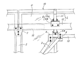
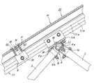
図1及び図2に示す太陽電池アレイの据付装置は、左右方向に長い太陽光発電パネルPが前後の傾斜方向に沿って4枚ずつ平面的に配列した太陽電池アレイ10を据付け対象としており、その傾斜方向における前後及び中間位置で且つ左右方向に所定間隔置きに地盤Gにスクリュー杭8が打ち込まれ、各スクリュー杭8上に角筒状の中空アルミ型材からなる垂直支柱2が立設され、これら垂直支柱2によって太陽電池アレイ10を支承する架台フレーム1が支持されている。なお、垂直支柱2とスクリュー杭8とは、前者の下端フランジ部2aと後者の上端フランジ部8aとの接合部をボルト止めして連結されている。また、垂直支柱2の高さは、太陽電池アレイ10の傾斜配置に対応して、前位置のものが低く、後位置のものが高く、中間位置のものが中間高さになっている。   The solar cell array installation apparatus shown in FIG. 1 and FIG. 2 has a solar cell array 10 in which four photovoltaic power generation panels P that are long in the left-right direction are arranged in a plane along the front-rear inclination direction as installation targets. Screw piles 8 are driven into the ground G at predetermined intervals in the front-rear and middle positions in the inclined direction and in the left-right direction, and vertical pillars 2 made of a rectangular hollow aluminum mold material are erected on each screw pile 8. The vertical frame 2 supports the gantry frame 1 that supports the solar cell array 10. In addition, the vertical support | pillar 2 and the screw pile 8 are connected by bolting the junction part of the former lower end flange part 2a and the latter upper end flange part 8a. Moreover, the height of the vertical support | pillar 2 respond | corresponds to the inclination arrangement | positioning of the solar cell array 10, the thing of a front position is low, the thing of a back position is high, and the thing of an intermediate position is intermediate height.

架台フレーム1は、太陽電池アレイ10の直下に配置した前後方向に沿う複数の縦桟11と、これら縦桟11を受ける形で下側に配置した左右方向に沿う複数の横桟12とが、相互の交叉位置で結合金具6を介して格子状に結合されてなる。そして、垂直支柱2は、太陽電池アレイ10において前後2枚の太陽光発電パネルPからなる矩形単位U毎に、前後左右の4本で支承する配置構成として、各々の上端部が架台フレーム1の横桟12に対して連結金具7を介して連結固定されている。また、太陽電池アレイ10は、前後の端縁部と前後方向における太陽光発電パネルP,P同士の隣接位置において、取付金具9を介して架台フレーム1の縦桟11に取り付けられている。なお、架台フレーム1の縦桟11及び横桟12は角筒状の中空アルミ型材からなり、その縦桟11は前記矩形単位Uで左右2本が平行配置し、横桟12は太陽電池アレイ10の前後部と中間部の3本が平行配置している。   The gantry frame 1 includes a plurality of vertical bars 11 arranged in the front-rear direction arranged directly below the solar cell array 10 and a plurality of horizontal bars 12 arranged in the left-right direction so as to receive the vertical bars 11. They are coupled in a lattice shape via coupling fittings 6 at the crossing positions. And as for the vertical support | pillar 2, as for the arrangement structure supported by 4 units | sets of front and back, right and left for every rectangular unit U which consists of two photovoltaic power generation panels P in the solar cell array 10, each upper end part of the frame 1 It is fixedly connected to the horizontal rail 12 via a connecting bracket 7. Further, the solar cell array 10 is attached to the vertical beam 11 of the gantry frame 1 via the mounting bracket 9 at the adjacent positions of the photovoltaic power generation panels P, P in the front and rear end portions and the front and rear direction. Note that the vertical beam 11 and the horizontal beam 12 of the gantry frame 1 are made of a rectangular tubular hollow aluminum material, and the vertical beam 11 is arranged in parallel in the rectangular unit U, and the horizontal beam 12 is a solar cell array 10. The front and rear parts and the middle part are arranged in parallel.

また、太陽電池アレイ10の前記矩形単位U毎に、該矩形単位の中央部分において架台フレーム1の左右の縦桟11,11間に円筒状の中空アルミ型材からなるブレース取付桟13がブラケット5A,5Aを介して架設されると共に、前側及び後側における左右の垂直支柱2,2間にも円筒状の中空アルミ型材からなる胴桟14がブラケット5B,5Bを介して架設されている。そして、ブレース取付桟13の左右の各端部と、前後の胴桟14,14における各垂直支柱2の根元近傍との間に、角筒状の中空アルミ型材からなる2本のブレース3,3が各々上下端部で止着金具4を介して止着して側面視逆V字形に配置している。更に、前後の垂直支柱2,2の根元部間には、偏平な角筒状の中空アルミ型材からなる補強桟16が架設されている。   In addition, for each rectangular unit U of the solar cell array 10, a brace mounting bar 13 made of a cylindrical hollow aluminum mold is provided between the left and right vertical bars 11 and 11 of the gantry frame 1 at the central portion of the rectangular unit. A trunk frame 14 made of a cylindrical hollow aluminum mold is also installed between brackets 5B and 5B between the left and right vertical columns 2 and 2 on the front side and the rear side. Between the left and right end portions of the brace mounting bar 13 and the vicinity of the base of each vertical column 2 in the front and rear trunk bars 14, 14, two braces 3, 3 made of a rectangular hollow aluminum mold material are used. Are fixed at the upper and lower end portions via the fixing metal fittings 4 and arranged in an inverted V shape in side view. Further, between the base portions of the front and rear vertical columns 2 and 2, a reinforcing bar 16 made of a flat rectangular tube-shaped hollow aluminum mold is installed.

しかして、ブレース取付桟13の左右端部は左右の垂直支柱2,2に対して左右方向中央寄りに位置するため、該ブレース取付桟13に上端部を止着した左右各対のブレース3,3は、図2に示すように前後方向から見てハの字形に配置している。従って、架台フレーム1と、前記矩形単位U毎に各4本の垂直支柱2及びブレース5と、補強桟16とからなる架台構体は、左右及び前後の両方向でトラス構造を構成している。なお、図3に示すように、ブレース取付桟13の左右の各端部では、前後2本のブレース3,3に対応する一対の止着金具4,4が上側ブラケット5Aの両側に隣接して当該ブレース取付桟13に嵌装固定されている。   Since the left and right end portions of the brace mounting bar 13 are located closer to the center in the left and right direction with respect to the left and right vertical columns 2 and 2, each pair of left and right braces 3, whose upper ends are fixed to the brace mounting bar 13. As shown in FIG. 2, 3 is arranged in a square shape when viewed from the front-rear direction. Therefore, the gantry structure including the gantry frame 1, the four vertical columns 2 and braces 5, and the reinforcing bars 16 for each rectangular unit U constitutes a truss structure in both the left and right and front and rear directions. As shown in FIG. 3, at the left and right ends of the brace mounting bar 13, a pair of fastening brackets 4, 4 corresponding to the two front and rear braces 3, 3 are adjacent to both sides of the upper bracket 5A. The brace mounting bar 13 is fitted and fixed.

図3〜図5で示すように、架台フレーム1の縦桟11と横桟12とを結合する結合金具6は、角筒状の横桟12が両側面を垂直にする配設姿勢であって前後方向に傾斜した角筒状の縦桟11に対して面接触しないため、縦桟11側の上部材6Aと横桟12側の下部材6Bとの2部材にて構成されている。その上部材6Aは、平板部61の上面側に一対の挟持片62,62が平行突設されて上向きコ字状の抱持枠部6aを形成しており、該抱持枠部6a内に縦桟11を抱持した状態で、その抱持位置に側方から貫通させたボルトBにナットNを螺合緊締することにより、該縦桟11に固定されている。また、下部材6Bは、傾斜上板部65の下面側に一対の挟持片66,67が垂設されて下向きコ字状の抱持枠部6bを形成しており、該抱持枠部6内に横桟12を抱持した状態で、その抱持位置に側方から貫通させたボルトBにナットNを螺合緊締することにより、該縦桟12に固定されている。そして、上部材6Aと下部材6Bとは、前者の平板部61に後者の傾斜上板部65を接合した状態で、その接合部をボルトBとナットNにて連結している。なお、下部材6Bの後部側の挟持片67は、縦桟11の傾斜に対応してくの字状に曲折している。   As shown in FIG. 3 to FIG. 5, the connecting bracket 6 that connects the vertical beam 11 and the horizontal beam 12 of the gantry frame 1 has an arrangement posture in which the rectangular tube-shaped horizontal beam 12 has both side surfaces vertical. Since it does not come into surface contact with the rectangular columnar vertical beam 11 inclined in the front-rear direction, it is composed of two members, an upper member 6A on the vertical beam 11 side and a lower member 6B on the horizontal beam 12 side. The upper member 6A has a pair of sandwiching pieces 62, 62 projecting in parallel on the upper surface side of the flat plate portion 61 to form an upward U-shaped holding frame portion 6a, and in the holding frame portion 6a. In a state where the vertical beam 11 is held, the nut N is screwed and tightened to the bolt B penetrating from the side to the holding position, thereby being fixed to the vertical beam 11. Further, the lower member 6B has a pair of holding pieces 66, 67 suspended from the lower surface side of the inclined upper plate portion 65 to form a downward U-shaped holding frame portion 6b. In a state where the horizontal beam 12 is held inside, the nut N is screwed and fastened to the bolt B penetrating from the side to the holding position, thereby being fixed to the vertical beam 12. The upper member 6 </ b> A and the lower member 6 </ b> B are connected by bolts B and nuts N in a state where the latter inclined upper plate portion 65 is joined to the former flat plate portion 61. The holding piece 67 on the rear side of the lower member 6 </ b> B is bent in a U-shape corresponding to the inclination of the vertical beam 11.

図4(a)及び図5(a)に示すように、架台フレーム1の角筒状の縦桟11及び横桟12は、上下部が幅広の角枠部11a,12aとなり、これによって両側面の中央部に凹陥部11b,12bを有している。一方、結合金具6の上下部材6A,6Bの抱持枠部6a,6bは、図4(b)及び図5(b)で詳細に示すように、各々対向する内面側に一対の凸条部63,63、68,68が設けてあり、両凸条部63,63、68,68を縦桟11及び横桟12の凹陥部11b,12bに嵌入することにより、角枠部11a,12aを上下方向離脱不能で且つ長手方向摺動可能に抱持している。しかして、上下部材6A,6Bを縦桟11及び横桟12に固定するボルトBは、両凸条部63,63間、68,68間の溝部64、69で側方から貫通しており、ナットNの螺合緊締によって両凸条部63,63、68,68が縦桟11及び横桟12の凹陥部11b,12bに押接する。   As shown in FIGS. 4 (a) and 5 (a), the rectangular tube-like vertical beam 11 and the horizontal beam 12 of the gantry frame 1 become wide rectangular frame portions 11a, 12a on both sides. In the central part of this, recesses 11b and 12b are provided. On the other hand, the holding frame portions 6a and 6b of the upper and lower members 6A and 6B of the coupling fitting 6 have a pair of ridges on the inner surfaces facing each other, as shown in detail in FIGS. 4 (b) and 5 (b). 63, 63, 68, 68 are provided, and both the ridges 63, 63, 68, 68 are fitted into the recessed portions 11b, 12b of the vertical beam 11 and the horizontal beam 12, so that the rectangular frame portions 11a, 12a are formed. It is held so that it cannot be detached in the vertical direction and can slide in the longitudinal direction. Thus, the bolt B for fixing the upper and lower members 6A, 6B to the vertical beam 11 and the horizontal beam 12 penetrates from the side by the groove portions 64, 69 between both the convex strip portions 63, 63, 68, 68, The two protruding strips 63, 63, 68, 68 are pressed against the recessed portions 11 b, 12 b of the vertical beam 11 and the horizontal beam 12 by screwing and tightening the nut N.

架台フレーム1の横桟12と垂直支柱2との連結部に介在する連結金具7は、図4(a)に示すように、上向き開放コ字形で幅狭の上向き抱持枠部7aと、下向き開放コ字形で幅広の下向き抱持枠部7bとが一体化した形状を有しており、下向き抱持枠部7bで垂直支柱2の上端部を抱持すると共に、上向き抱持枠部7aで横桟12を抱持した状態で、これら抱持位置に側方から貫通させたボルトBにナットNを螺合緊締することにより、該横桟12と垂直支柱2とを連結固定されている。しかして、上向き抱持枠部7aによる横桟12との連結部では、該横桟12の内部に角形の鋼製又はアルミ製の補強パイプ15が挿嵌されており、ボルトBが該補強パイプ15を貫通するように設定されている。   As shown in FIG. 4 (a), the connecting bracket 7 interposed in the connecting portion between the horizontal beam 12 and the vertical column 2 of the gantry frame 1 has an upwardly open U-shaped narrow holding portion 7a and a downwardly holding frame portion 7a. An open U-shaped and wide downward holding frame portion 7b has an integrated shape. The downward holding frame portion 7b holds the upper end of the vertical column 2 and the upward holding frame portion 7a. In a state where the horizontal beam 12 is held, the horizontal beam 12 and the vertical column 2 are connected and fixed by screwing and tightening a nut N to the bolt B penetrating from the side to the holding position. Thus, at the connecting portion with the horizontal rail 12 by the upward holding frame portion 7a, a square steel or aluminum reinforcing pipe 15 is inserted into the horizontal rail 12, and the bolt B is connected to the reinforcing pipe. 15 is set to penetrate.

また、図4(b)で詳細に示すように、連結金具7の上向き抱持枠部7aには、結合金具6の上下部材6A,6Bの抱持枠部6a,6bと同様に、各々対向する内面側に一対の凸条部71,71が設けてあり、両凸条部71,71を横桟12の凹陥部12bに嵌入することにより、角枠部12aを上下方向離脱不能で且つ長手方向摺動可能に抱持するように構成されている。そして、前記ボルトBは両凸条部71,71間の溝部72を貫通しており、ナットNの螺合緊締によって両凸条部71,71が横桟12の凹陥部12bに押接すると共に、横桟12の両側の凹陥部12b,12bの各々内面側にも長手方向に沿う一対の凸条12c,12cが形成されているため、該ナットNの螺合緊締による締付力が凸条12c,12cを介して補強パイプ15に加わるようになっている。   Further, as shown in detail in FIG. 4B, the upward holding frame portion 7a of the coupling metal 7 is respectively opposed to the holding frame portions 6a and 6b of the upper and lower members 6A and 6B of the coupling metal 6. A pair of ridges 71, 71 are provided on the inner surface side, and by inserting both ridges 71, 71 into the recesses 12 b of the horizontal rail 12, the square frame 12 a cannot be detached in the vertical direction and is long. It is configured to be slidable in the direction. And the said volt | bolt B has penetrated the groove part 72 between both the protruding item | line parts 71 and 71, and both the protruding item | line parts 71 and 71 are press-contacted to the recessed part 12b of the horizontal rail 12 by the screwing tightening of the nut N, Since a pair of ridges 12c, 12c along the longitudinal direction are also formed on the inner surfaces of the recessed portions 12b, 12b on both sides of the horizontal rail 12, the tightening force due to the threaded tightening of the nut N is applied to the ridge 12c. , 12c is added to the reinforcing pipe 15.

ブレース3の上下端部をブレース取付桟13及び胴桟14に止着する止着金具4は、図6,図8,図9に示すように、円環部4aから一対のブレース取付片4b,4bが外側へ延出した形状であり、円環部4aにブレース取付桟13又は胴桟14を挿嵌させ、その挿嵌位置で貫通させたボルトBにナットNを螺合緊締することにより、ブレース取付桟13又は胴桟14に枢着すると共に、両ブレース取付片4b,4b間にブレース3の上端側又は下端側を挟み、その挟み込み位置で貫通させたボルトBにナットNを螺合緊締することにより、ブレース3の上下端部を枢着している。なお、図9において、Hはボルト挿通孔、Wはワッシャーを示す。   As shown in FIGS. 6, 8, and 9, the fastening metal fitting 4 that fastens the upper and lower ends of the brace 3 to the brace attachment frame 13 and the trunk frame 14 includes a pair of brace attachment pieces 4 b, 4b is a shape extending outward, and the brace mounting bar 13 or the trunk bar 14 is inserted into the annular part 4a, and the nut N is screwed and tightened to the bolt B penetrated at the insertion position, It is pivotally attached to the brace mounting bar 13 or the body bar 14, and the upper end side or the lower end side of the brace 3 is sandwiched between the brace mounting pieces 4b and 4b, and the nut N is screwed and tightened to the bolt B that is penetrated at the sandwiched position. By doing so, the upper and lower ends of the brace 3 are pivotally attached. In FIG. 9, H indicates a bolt insertion hole, and W indicates a washer.

架台フレーム1の縦桟11にブレース取付桟13を架設するブラケット5Aは、図7に示すように、ブレース取付桟13を挿嵌させる円環部51aを有するブラケット本体51と、縦桟11に固定する縦桟抱持金具52とで構成されている。その縦桟抱持金具52は、結合金具6の上部材6Aと同様の縦断面形状を有し、上向きコ字状の抱持枠部52aで縦桟11を抱持した状態で、その抱持位置に貫通させたボルトBにナットNを螺合緊締することにより、該縦桟11に固定されている。そして、ブラケット本体51と縦桟抱持金具52とは、両者の接合した平板部51b,52bをボルト止めして一体化している。また、垂直支柱2の根元部に胴桟14を架設するブラケット5Bは、図9に示すように、ブラケット5Aのブラケット本体51と同様の形態であり、円環部51aに胴桟14を挿嵌した状態で、その挿嵌位置で該円環部51a及び垂直支柱2に貫通させたボルトBにナットNを螺合緊締して胴桟14を固定すると共に、垂直支柱2の側面に当接した平板部51bで貫通させたボルトBにナットNを螺合緊締して当該垂直支柱2に固着されている。   As shown in FIG. 7, the bracket 5 </ b> A for installing the brace mounting bar 13 on the vertical bar 11 of the gantry frame 1 is fixed to the vertical bar 11 and the bracket body 51 having an annular portion 51 a into which the brace mounting bar 13 is inserted. It is comprised with the vertical beam holding | maintenance metal fitting 52 to do. The vertical beam holding bracket 52 has a vertical cross-sectional shape similar to that of the upper member 6A of the coupling metal 6, and holds the vertical beam 11 in a state where the vertical beam 11 is held by an upward U-shaped holding frame portion 52a. The nut N is screwed and fastened to the bolt B penetrated to the position, thereby being fixed to the vertical beam 11. And the bracket main body 51 and the vertical beam holding | maintenance metal fitting 52 are bolted and integrated with the flat plate part 51b and 52b which both joined. Further, as shown in FIG. 9, the bracket 5B for erection of the trunk frame 14 at the base portion of the vertical column 2 has the same form as the bracket body 51 of the bracket 5A, and the trunk frame 14 is inserted into the annular portion 51a. In this state, the nut N is screwed and tightened to the bolt B passed through the annular portion 51a and the vertical column 2 at the insertion position, thereby fixing the body frame 14 and contacting the side surface of the vertical column 2 A nut N is screwed and tightened to a bolt B penetrated by the flat plate portion 51b and is fixed to the vertical column 2.

太陽電池アレイ10を架台フレーム1の縦桟11に取り付ける取付金具9は、図5及び図6に示すように、結合金具6の上部材6Aと同様の縦断面形状を有する抱持枠部91と、この抱持枠部91上に配置したスペーサー92と、U字形係止片93とで構成されている。そして、この取付金具9では、抱持枠部91で架台フレーム1の縦桟11を上方から抱持してボルト止めすると共に、スペーサー92を前後方向で隣接する太陽光発電パネルP,Pの周枠F,F間、太陽電池アレイ10の前後端縁では該周枠と外側の当板94との間に配置させ、U字形係止片93の張出した両端部を周枠F,Fの上面又は該周枠と当板の上面に係止し、抱持枠部91及び縦桟11と該U字形係止片93を下方から貫通するボルトBにナットNを螺合緊締することにより、縦桟11に各太陽光発電パネルPを固定している。   As shown in FIGS. 5 and 6, the mounting bracket 9 for attaching the solar cell array 10 to the vertical rail 11 of the gantry frame 1 includes a holding frame portion 91 having the same vertical cross-sectional shape as the upper member 6 </ b> A of the coupling bracket 6. The spacer 92 is disposed on the holding frame portion 91 and a U-shaped locking piece 93. In this mounting bracket 9, the vertical frame 11 of the gantry frame 1 is held from above by the holding frame portion 91 and bolted, and the spacer 92 is surrounded by the solar power generation panels P, P adjacent in the front-rear direction. Between the frames F and F, the front and rear edges of the solar cell array 10 are arranged between the peripheral frame and the outer abutment plate 94, and the protruding ends of the U-shaped locking piece 93 are the upper surfaces of the peripheral frames F and F. Alternatively, the nut N is screwed and fastened to the bolt B passing through the holding frame portion 91 and the vertical rail 11 and the U-shaped locking piece 93 from below by locking the peripheral frame and the upper surface of the plate. Each photovoltaic power generation panel P is fixed to the crosspiece 11.

なお、止着金具4、ブラケット5Aのブラケット本体51及び縦桟抱持金具52、ブラケット5B、結合金具6の上下部材6A,6B、連結金具7、上向き抱持枠部7a、取付金具9の抱持枠部91は、いずれもアルミ型材の切断短材からなる。そして、これらアルミ型材ならびに既述の中空アルミ型材は、アルミニウム及びアルミニウム合金からなるものを包含する。   It should be noted that the fastening bracket 4, the bracket body 51 of the bracket 5 </ b> A and the vertical beam holding bracket 52, the bracket 5 </ b> B, the upper and lower members 6 </ b> A and 6 </ b> B of the coupling bracket 6, the connecting bracket 7, the upward holding frame portion 7 a, and the mounting bracket 9. Each of the holding frame portions 91 is made of a short cut material of an aluminum mold material. The aluminum mold material and the hollow aluminum mold material described above include those made of aluminum and aluminum alloys.

上記構成の太陽電池アレイの据付装置では、太陽電池アレイ10を支承する架台フレーム1は該太陽電池アレイ10の矩形単位U毎に前後左右の四本の垂直支柱2で支持されるが、該矩形単位U毎に4本のブレース3が前後方向及び左右方向に傾斜して配置していることにより、架台フレーム1、垂直支柱2、ブレース3、胴桟14、補強桟16よりなる架台構体がトラス構造を形成して非常に高強度になり、強風に晒され易い場所でも大きな支持強度及び耐風圧強度を確保でき、据付け場所の制約が少なくなる。また、架台フレーム1の縦桟11及び横桟12、垂直支柱2、ブレース3、ブレース取付桟13、胴桟14、補強桟16がいずれも軽量な中空アルミ材であるため、据付装置全体としての重量が軽減すると共に、その据付け施工時の作業性も向上する。加えて、上記のように架台構体として高強度であるため、垂直支柱2に軽く細い中空アルミ材を用いることで材料コストも低減される。   In the solar cell array installation apparatus having the above-described configuration, the gantry frame 1 that supports the solar cell array 10 is supported by four vertical columns 2 on the front, rear, left, and right for each rectangular unit U of the solar cell array 10. Since four braces 3 are inclined in the front-rear direction and the left-right direction for each unit U, the frame structure including the frame 1, the vertical column 2, the brace 3, the body frame 14, and the reinforcement frame 16 is trussed. A structure is formed so that the strength becomes very high, and a large support strength and wind pressure strength can be secured even in a place that is easily exposed to strong winds, and there are less restrictions on the installation location. In addition, since the vertical beam 11 and the horizontal beam 12, the vertical column 2, the brace 3, the brace mounting frame 13, the body frame 14, and the reinforcing frame 16 of the gantry frame 1 are all lightweight hollow aluminum materials, The weight is reduced, and the workability during installation is improved. In addition, since the frame structure has high strength as described above, the material cost can be reduced by using a light and thin hollow aluminum material for the vertical support 2.

加えて上記実施形態では、各ブレース3による支持位置が前記矩形単位Uにおける前後左右の4本の垂直支柱2の位置を頂点とする矩形内の中央側にあるから、該矩形単位Uのサイズが大きくなっても、該中央側での架台フレーム1の撓み変形を防止でき、その撓み変形に伴う太陽光発電パネルPの損傷や発電効率低下を回避できると共に、各ブレース3に加わる荷重の負荷が垂直支柱2の根元側で受け止められ、該負荷が垂直支柱2に対する曲げ力として作用しにくいため、該垂直支柱2が細い中空アルミ材であっても充分な耐久性が得られる。   In addition, in the above-described embodiment, the support position by each brace 3 is on the center side in the rectangle with the positions of the four vertical struts 2 on the front, rear, left and right in the rectangular unit U as the apexes. Even if it becomes larger, it is possible to prevent the deformation of the gantry frame 1 at the center side, to avoid damage to the photovoltaic power generation panel P and a decrease in power generation efficiency due to the bending deformation, and to apply a load applied to each brace 3. Since it is received on the base side of the vertical support 2 and the load is less likely to act as a bending force on the vertical support 2, sufficient durability can be obtained even if the vertical support 2 is a thin hollow aluminum material.

そして、架台フレーム1に組み付けられるブレース取付桟13と、垂直支柱2の下端部間に架設される胴桟14とが円筒状をなし、これらブレース取付桟13及び胴桟14に外嵌して固定される止着金具4を介して、各ブレース3の上下端部をブレース取付桟13及び胴桟14に止着する構造であるため、各ブレース3の傾斜角度及び傾斜方向が異なるにも関わらず、同じ止着金具4を用いてブレース取付桟13及び胴桟13に対する嵌合位置と回転姿勢を調整することで対応でき、太陽電池アレイ10の全体サイズの違いにも共通部材を使用することが可能となり、それだけ材料コストを低減できると共に、各ブレース3を同じ操作手順で止着できるので施工作業も容易になる。   The brace mounting bar 13 assembled to the gantry frame 1 and the body frame 14 installed between the lower end portions of the vertical column 2 form a cylindrical shape, and are fitted and fixed to the brace mounting frame 13 and the body frame 14. Since the upper and lower end portions of each brace 3 are fixed to the brace mounting bar 13 and the trunk bar 14 via the fixing metal fitting 4 that is made, the inclination angle and the inclination direction of each brace 3 are different. It is possible to cope with the problem by adjusting the fitting position and the rotation posture with respect to the brace mounting bar 13 and the body bar 13 using the same fastening metal fitting 4, and a common member can be used for the difference in the overall size of the solar cell array 10. Thus, the material cost can be reduced accordingly, and each brace 3 can be fixed by the same operation procedure, so that the construction work is facilitated.

特に、上記実施形態における止着金具4では、ブレース取付桟13又は胴桟14を挿嵌させる円環部4aから一対のブレース取付片4b,4bが外側へ延出し、両ブレース取付片4b,4b間にブレース3の上下端部を挟んで枢着するから、据付け施工に際して予めブレース取付桟13及び胴桟14に嵌装しておいて、ブレース3の先端側の向きと位置に応じて、ブレース取付桟13及び胴桟14に対する嵌合位置と回転姿勢を調整することにより、該ブレース3の止着操作が極めて容易になるという利点がある。更に、ブレース取付桟13が架台フレーム1の隣接する縦材11,11間にブラケット5Aを介して架設され、このブラケット5Aがブレース取付桟13を挿嵌させる円環部51aと架台フレーム1の縦材11に取り付ける桟抱持金具52とを備えるから、架台フレーム1に対して該ブレース取付桟13を容易に且つ確実に強固に取り付けることができる。   In particular, in the fastening bracket 4 in the above-described embodiment, the pair of brace mounting pieces 4b and 4b extend outward from the annular portion 4a into which the brace mounting bar 13 or the trunk bar 14 is inserted, and both brace mounting pieces 4b and 4b. Since the upper and lower end portions of the brace 3 are sandwiched between them, the brace is fitted in advance to the brace mounting bar 13 and the body bar 14 at the time of installation work, and the brace according to the direction and position of the front end side of the brace 3 By adjusting the fitting position and the rotational posture with respect to the mounting bar 13 and the body bar 14, there is an advantage that the fastening operation of the brace 3 becomes extremely easy. Further, a brace mounting bar 13 is installed between adjacent vertical members 11 and 11 of the gantry frame 1 via a bracket 5A, and the bracket 5A is inserted between the annular part 51a into which the brace mounting bar 13 is inserted and the vertical frame of the gantry frame 1. Since the crosspiece mounting bracket 52 attached to the material 11 is provided, the brace mounting crosspiece 13 can be easily and securely attached firmly to the gantry frame 1.

一方、架台フレーム1の縦桟11と横桟12とが結合金具6を介して結合され、その縦桟11又は横桟12に対して各垂直支柱2が上端部で連結金具7を介して連結固定される構成であるから、傾斜配置される架台フレーム1を各垂直支柱2に対して容易に且つ確実に強固に取り付けることができる。また、結合金具6及び連結金具7が抱持枠部6a,6b,7aで架台フレーム1の角筒状の縦桟11及び/又は横桟12を抱持し、その抱持位置において側方から貫通させたボルトBにナットNを螺合緊締することから、両金具6,7の該縦桟11及び/又は横桟12に対する取付け部分が高強度になると共に、その取付け作業を容易に且つ確実に行える。特に、実施形態のように連結金具7による横桟12と垂直支柱2の連結位置に鋼製の補強パイプ15を挿嵌し、その挿嵌部分に前記ボルトBを貫通させる構成では、架台フレーム1に対する該垂直支柱2の固定部分が極めて高強度となり、それだけ架台構体としての強度も向上する。   On the other hand, the vertical beam 11 and the horizontal beam 12 of the gantry frame 1 are coupled via the coupling bracket 6, and each vertical column 2 is coupled to the vertical beam 11 or the lateral beam 12 via the coupling bracket 7 at the upper end. Because of the fixed configuration, the gantry frame 1 that is inclined can be easily and securely attached to each vertical column 2 firmly. Further, the coupling metal 6 and the coupling metal 7 hold the vertical cylindrical beam 11 and / or the horizontal beam 12 of the gantry frame 1 by the holding frame portions 6a, 6b, 7a, and from the side at the holding position. Since the nut N is screwed and tightened to the bolt B that has been passed through, the attachment portions of the metal fittings 6 and 7 to the vertical beam 11 and / or the horizontal beam 12 become high in strength, and the installation work is easy and reliable. It can be done. In particular, in the configuration in which the steel reinforcing pipe 15 is inserted into the connecting position of the horizontal beam 12 and the vertical column 2 by the connecting metal fitting 7 as in the embodiment, and the bolt B is passed through the insertion portion, the frame 1 The fixing portion of the vertical column 2 with respect to is extremely high in strength, and the strength as a frame structure is improved accordingly.

更に、実施形態の如く架台フレーム1の角筒状の縦桟11及び横桟12の上下部が幅広の角枠部11a,12aを形成し、結合金具6及び連結金具7の各抱持枠部6a,6b,7aが該角枠部11a,12aを上下方向離脱不能で且つ長手方向摺動可能に抱持する構成では、据付け施工に際し、架台フレーム1の縦桟11及び横桟12に対して予め両金具6,7を嵌装しておき、組み付け時に必要位置まで移動させることで、その作業操作をより容易に行えるという利点がある。   Further, as in the embodiment, the upper and lower portions of the rectangular columnar vertical beam 11 and the horizontal beam 12 of the gantry frame 1 form wide rectangular frame portions 11a and 12a, and the holding frame portions of the coupling metal 6 and the coupling metal 7 are formed. 6a, 6b, 7a is configured to hold the square frame portions 11a, 12a so as not to be vertically disengageable and slidable in the longitudinal direction, with respect to the vertical beam 11 and the horizontal beam 12 of the gantry frame 1 during installation work. There is an advantage that the work operation can be performed more easily by fitting both the metal fittings 6 and 7 in advance and moving them to the required position at the time of assembly.

加えて、実施形態の結合金具6及び連結金具7では、架台フレーム1の角筒状の縦桟11及び横桟12に対して連結金具7をボルトBとナットNを用いて取り付ける際、そのナットNの螺合緊締により、抱持枠部6a,6b,7aの対向する内面側の一対の凸条部63,63、68,68、72,72が縦桟11及び横桟12の凹陥部11b,12bに押接するから、該ナットNによる締付力が広面積に分散して加わるから、該締付力の局所的集中による縦桟11及び横桟12の歪み変形を生じにくく、それだけ締付力を大きくして強固な結合状態にすることができるという利点がある。本実施形態の場合、このような締付力の分散による歪み変形の抑制効果は、ブラケット5Aの縦桟抱持金具52による縦桟11に対する固定部や、取付金具9の抱持枠部91による縦桟11に対する固定部でも同様に得られる。なお、特に連結金具7による横桟12と垂直支柱2の連結位置に前記の補強パイプ15を挿嵌する構成では、実施形態のように横桟12の両側の凹陥部12b,12bの各々内面側にも長手方向に沿う一対の凸条12c,12cを設け、ナットNの螺合緊締による締付力が凸条12c,12cを介して補強パイプ15に加わるようにすれば、該横桟12の歪み変形をより確実に防止できる。   In addition, in the coupling bracket 6 and the coupling bracket 7 of the embodiment, when the coupling bracket 7 is attached to the rectangular cylindrical vertical beam 11 and the horizontal beam 12 of the gantry frame 1 using the bolt B and the nut N, the nut By screwing and tightening N, the pair of protruding strips 63, 63, 68, 68, 72, 72 on the inner surface facing the holding frame portions 6a, 6b, 7a are formed into the vertical beam 11 and the recessed portion 11b of the horizontal beam 12. , 12b, so that the tightening force by the nut N is distributed over a wide area, so that the vertical beam 11 and the horizontal beam 12 are not easily deformed due to local concentration of the tightening force, and the tightening is performed accordingly. There is an advantage that the force can be increased to form a strong bonded state. In the case of the present embodiment, the effect of suppressing distortion deformation due to such dispersion of the tightening force is due to the fixing portion of the bracket 5A to the vertical beam 11 by the vertical beam holding bracket 52 and the holding frame portion 91 of the mounting bracket 9. It can be obtained in the same manner in the fixed portion with respect to the vertical beam 11. In particular, in the configuration in which the reinforcing pipe 15 is inserted into the connecting position of the horizontal beam 12 and the vertical column 2 by the connecting bracket 7, each of the recessed portions 12b, 12b on the both sides of the horizontal beam 12 as shown in the embodiment. If a pair of ridges 12c, 12c along the longitudinal direction is provided and the tightening force by screwing and tightening the nut N is applied to the reinforcing pipe 15 via the ridges 12c, 12c, Strain deformation can be prevented more reliably.

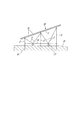
本発明を適用する太陽電池アレイ10としては、上記実施形態では傾斜する前後方向に沿って4枚の太陽光発電パネルPが配置する構成を例示したが、前後方向の該発電パネルPの配置枚数と全体幅には特に制約はない。しかして、据付装置における前後(傾斜)方向に沿う垂直支柱2の本数は、太陽電池アレイ10の前後方向の全体幅の広狭によって増減することになる。また、太陽電池アレイ10の左右方向の長さについては、敷地の広さと発電システムの規模及びレイアウトによる制約のみである。一方、太陽電池アレイ10の傾斜角度についても、据付場所の緯度に応じて年間平均で受光効率が最も高くなる角度とすればよく、赤道直下での0°から極地での90°まで任意に設定できる。因みに、太陽光発電パネルPの傾斜方向幅が1m程度である場合の、太陽電池アレイの全体幅と傾斜角度及び設置高さの違いによる据付装置の構成例を図10〜図12に示す。   As the solar cell array 10 to which the present invention is applied, the configuration in which the four photovoltaic power generation panels P are arranged along the inclined front-rear direction in the above embodiment is exemplified. However, the number of the power generation panels P arranged in the front-rear direction is exemplified. There is no particular restriction on the overall width. Therefore, the number of the vertical support | pillars 2 along the front-back (inclination) direction in an installation apparatus will increase / decrease with the breadth of the whole width | variety of the front-back direction of the solar cell array 10. FIG. Moreover, about the length of the solar cell array 10 in the left-right direction, there are only restrictions due to the size of the site, the scale of the power generation system, and the layout. On the other hand, the inclination angle of the solar cell array 10 may be set to an angle at which the light receiving efficiency becomes the highest on an average annually according to the latitude of the installation location, and is arbitrarily set from 0 ° immediately below the equator to 90 ° in the polar region. it can. Incidentally, FIG. 10 to FIG. 12 show configuration examples of the installation device depending on differences in the overall width, inclination angle, and installation height of the solar cell array when the inclination width of the photovoltaic power generation panel P is about 1 m.

まず、図10(a)の据付装置では、傾斜方向に2枚の太陽光発電パネルPが配置した全体幅の狭い太陽電池アレイ10Aを高位に設置するために、高くなった前後2本の垂直支柱2,2間に上下2本の補強桟16,16を架設すると共に、架台フレーム1の中間部と両垂直支柱2の根元部との間にブレース3,3を逆V字形に架設し、更に架台フレーム1の中間部と高い後部側の垂直支柱2の中間部との間にもブレース3を架設することで、架台構体としての全体強度を確保している。また、図10(b)の据付装置では、同様の太陽電池アレイ10Aを低位に設置するため、前後2本の垂直支柱2,2の根元部間に1本の補強桟16を架設し、架台フレーム1の中間部と両垂直支柱2の根元部との間にブレース3,3を逆V字形に架設することで、架台構体としての全体強度を確保できる。しかるに、図の実線と仮想線で示すように、太陽電池アレイ10Bの傾斜角度によってブレース3,3の逆V字形の開き角度が変わると共に、該傾斜角度が低く前後方向に長くなる場合は前後の垂直支柱2,2間の距離を拡げることになる。   First, in the installation apparatus of FIG. 10 (a), in order to install a solar cell array 10A having a narrow overall width in which two photovoltaic power generation panels P are arranged in an inclined direction at a high level, two vertical front and rear elevations are provided. Two upper and lower reinforcing bars 16 and 16 are installed between the columns 2 and 2, and braces 3 and 3 are installed in an inverted V shape between the middle part of the gantry frame 1 and the bases of the two vertical columns 2; Furthermore, the brace 3 is installed between the middle part of the gantry frame 1 and the middle part of the vertical column 2 on the high rear side, thereby ensuring the overall strength of the gantry structure. Further, in the installation apparatus of FIG. 10 (b), in order to install the similar solar cell array 10A at a low level, one reinforcing bar 16 is installed between the root portions of the two front and rear vertical columns 2, 2, By bracing the braces 3 and 3 in an inverted V shape between the middle portion of the frame 1 and the base portions of the two vertical struts 2, the overall strength of the gantry structure can be ensured. However, as shown by the solid line and the virtual line in the figure, the opening angle of the inverted V shape of the braces 3 and 3 changes depending on the inclination angle of the solar cell array 10B, and when the inclination angle is low and long in the front-rear direction, The distance between the vertical supports 2 and 2 will be increased.

図11(a)の据付装置では、傾斜方向に3枚の太陽光発電パネルPが配置した前後幅のやや広い太陽電池アレイ10Bを高位に設置するが、前記の太陽電池アレイ10Aの場合と同様に、前後2本の垂直支柱2,2間に上下2本の補強桟16,16を架設し、ブレース3を架台フレーム1の中間部と両垂直支柱2の根元部との間ならびに架台フレーム1の中間部と後部側の垂直支柱2の中間部との間に架設することで、架台構体としての全体強度を確保している。また、図11(b)の据付装置では、同様の太陽電池アレイ10Bを低位に設置するが、やはり前記の太陽電池アレイ10Aの場合と同様に、前後の垂直支柱2,2の根元部間に1本の補強桟16を架設し、架台フレーム1の中間部と両垂直支柱2の根元部との間にブレース3,3を逆V字形に架設することで、架台構体としての全体強度を確保しており、太陽電池アレイ10Bの傾斜角度によってブレース3,3の逆V字形の開き角度が変わることと、該傾斜角度が低い場合に前後の垂直支柱2,2間の距離を拡げることも同様である。   In the installation apparatus of FIG. 11A, the solar cell array 10B having a slightly wider front and rear width in which the three photovoltaic power generation panels P are arranged in the inclination direction is installed at a high level, but is the same as in the case of the solar cell array 10A. Further, two upper and lower reinforcing bars 16, 16 are installed between the two front and rear vertical struts 2, 2, and the brace 3 is placed between the middle part of the base frame 1 and the base part of the two vertical struts 2 and the base frame 1. The overall strength of the gantry structure is ensured by erection between the middle part of the vertical column and the middle part of the vertical column 2 on the rear side. Further, in the installation apparatus of FIG. 11B, the similar solar cell array 10B is installed at a low position, but, similarly to the case of the solar cell array 10A, between the root portions of the front and rear vertical columns 2, 2. One reinforcing bar 16 is installed, and braces 3 and 3 are installed in an inverted V shape between the middle part of the gantry frame 1 and the base parts of the two vertical columns 2, thereby ensuring the overall strength of the gantry structure. The opening angle of the inverted V-shaped braces 3 and 3 changes depending on the inclination angle of the solar cell array 10B, and the distance between the front and rear vertical columns 2 and 2 can be increased when the inclination angle is low. It is.

図12のの据付装置では、傾斜方向に4枚の太陽光発電パネルPが配置した前後幅の広い太陽電池アレイ10Cを設置するため、前後部と中間部の3本の垂直支柱2を用いると共に、前部と中間部の垂直支柱2,2の根元部と架台フレーム1との間、ならびに中間部と後部の垂直支柱2,2の根元部と架台フレーム1との間に、それぞれブレース3,3を逆V字形に架設し、また前後部と中間部の3本の垂直支柱2にわたって根元部間に補強桟16を架設することにより、架台構体としての全体強度を確保している。この場合、太陽電池アレイ10Cが大サイズで、その傾斜角度の違いによる前後方向の長さの変化が大きいため、前部の垂直支柱2に対して中間及び後部の垂直支柱2,2の位置が該傾斜角度が低いほど後方へ移動している。   In the installation apparatus of FIG. 12, in order to install a solar cell array 10C having a wide front-rear width in which four photovoltaic power generation panels P are arranged in an inclination direction, three vertical columns 2 of the front-rear part and the middle part are used. The braces 3, respectively, are arranged between the base of the vertical struts 2, 2 at the front and the middle and the gantry frame 1, and between the base of the vertical struts 2, 2 at the rear and the pedestal frame 1, respectively. 3 is installed in an inverted V-shape, and a reinforcing bar 16 is installed between the root portions over the three vertical columns 2 at the front and rear and the middle, thereby ensuring the overall strength of the gantry structure. In this case, since the solar cell array 10C is large in size and the change in the length in the front-rear direction due to the difference in inclination angle is large, the positions of the middle and rear vertical struts 2, 2 with respect to the front vertical strut 2 are The lower the angle of inclination, the more it moves backward.

なお、実施形態では太陽電池アレイ1の太陽光発電パネルPが横長であるために、該太陽電池アレイ1を架台フレーム1の縦桟11で支承しているが、太陽光発電パネルPが縦長の場合は該太陽電池アレイ1を架台フレーム1の横桟12で支承することになる。また、ブレース取付桟13は、実施形態では架台フレーム1の縦桟11,11間に左右方向に沿う形で架設しているが、該架台フレーム1の横桟12,12間に前後方向に沿う形で架設してもよい。また、実施形態では各垂直支柱2をスクリュー杭8上に立設しているが、スクリュー杭8に代えてPC杭の如きコンクリート杭を用いてもよく、更に陸屋根のような杭打ち不能な据付場所ではコンクリート製の土台上に垂直支柱2を立設すればよい。   In the embodiment, since the solar power generation panel P of the solar cell array 1 is horizontally long, the solar cell array 1 is supported by the vertical rail 11 of the gantry frame 1, but the solar power generation panel P is vertically long. In this case, the solar cell array 1 is supported by the horizontal rail 12 of the gantry frame 1. In the embodiment, the brace mounting bar 13 is installed between the vertical bars 11 and 11 of the gantry frame 1 along the left-right direction. However, the brace mounting bar 13 extends between the horizontal bars 12 and 12 of the gantry frame 1 along the front-rear direction. You may build in the form. Further, in the embodiment, each vertical support 2 is erected on the screw pile 8, but a concrete pile such as a PC pile may be used instead of the screw pile 8, and a non-pileable installation such as a flat roof is possible. At the place, the vertical support 2 may be erected on a concrete base.

本発明による太陽電池アレイの据付装置では、前後及び左右に隣接した4本の垂直支柱2位置を頂点とする矩形内におけるブレース3の配置本数及び配置間隔と、各ブレース3の傾斜角度は、実施形態による例示構成に限らず、該矩形単位のサイズや架台フレーム1の傾斜角度等に応じて種々設定可能である。しかして、ブレース3によるトラス構造の架台構体として、例えば図13に示すように、架台フレーム1に対して各ブレース3の上端側を垂直支柱2の上端近傍でブレース取付桟(図示省略)に止着すると共に、その下端側を前後に隣接する垂直支柱2,2の中間位置で土台17上に適当な取付手段を介して止着することにより、前後に隣接する垂直支柱2,2間に2本のブレース3,3が既述の実施形態とは逆にV字形をなすように配設する構成も採用可能である。ただし、この場合には、トラス構造によって架台構体としての強度は増すが、ブレース3による架台フレーム1の支承位置が前記矩形内の中央寄りにならないため、該矩形のサイズが大きい場合にその中央側での架台フレーム1の撓み変形を生じ易くなる。   In the solar cell array installation apparatus according to the present invention, the number of braces 3 placed and the spacing between the four vertical struts 2 adjacent to the front and rear and right and left, and the inclination angle of each brace 3 are Not limited to the exemplary configuration according to the form, various settings can be made according to the size of the rectangular unit, the inclination angle of the gantry frame 1 and the like. As shown in FIG. 13, for example, as shown in FIG. 13, the upper end side of each brace 3 is fixed to a brace mounting bar (not shown) in the vicinity of the upper end of the vertical column 2 as the frame structure of the truss structure by the brace 3. At the same time, the lower end side is fixed on the base 17 at an intermediate position between the vertical struts 2 and 2 adjacent to each other by an appropriate attachment means, so that 2 A configuration in which the braces 3 and 3 of the book are arranged so as to form a V shape contrary to the above-described embodiment can also be adopted. However, in this case, although the strength as the gantry structure is increased by the truss structure, the support position of the gantry frame 1 by the brace 3 is not close to the center in the rectangle, so that the center side when the size of the rectangle is large It becomes easy to produce the bending deformation of the mount frame 1 at.

更に、本発明においては、止着金具4、ブラケット5A,5B、結合金具6、連結金具7の形態とこれらの取付構造、太陽電池アレイ10の架台フレーム1に対する取付構造、架台フレーム1の縦桟11及び横桟12、ブレース取付桟13、胴桟14、垂直支柱2、ブレース3に用いる中空アルミ型材の断面形状等、細部構成については実施形態以外に種々設計変更可能である。   Furthermore, in the present invention, the form of the fixing metal fittings 4, brackets 5A and 5B, coupling metal fittings 6 and connecting metal fittings 7 and their attachment structures, the attachment structure of the solar cell array 10 to the frame frame 1, the vertical beam of the frame frame 1 11 and various configurations other than the embodiment can be changed in detail, such as a cross-sectional shape of a hollow aluminum mold member used for the horizontal rail 12, the brace mounting rail 13, the trunk rail 14, the vertical column 2, and the brace 3.

1 架台フレーム
10 太陽電池アレイ
11 縦桟
11a 角枠部
11b 凹陥部
12 横桟
12a 角枠部
12b 凹陥部
13 ブレース取付桟
14 胴桟
15 補強パイプ
2 垂直支柱
3 ブレース
4 止着金具
4a 円環部
4b ブレース取付片
5A,5B ブラケット
51a 円環部
52 桟抱持金具(取付基部)
6 結合金具
6a,6b 抱持枠部
63,68 凸条部
64,69 溝部
7 連結金具
7a 抱持枠部
71 凸条部
72 溝部
B ボルト
N ナット
P 太陽光発電パネル
U 太陽電池アレイの矩形単位
DESCRIPTION OF SYMBOLS 1 Base frame 10 Solar cell array 11 Vertical beam 11a Square frame part 11b Recessed part 12 Horizontal beam 12a Square frame part 12b Recessed part 13 Brace mounting frame 14 Trunk frame 15 Reinforcement pipe 2 Vertical support | pillar 3 Brace 4 Fastening bracket 4a Ring part 4b Brace mounting piece 5A, 5B Bracket 51a Annular portion 52 Crosspiece mounting bracket (mounting base)
6 coupling metal fittings 6a, 6b holding frame portion 63, 68 protruding strip portion 64, 69 groove portion 7 connecting bracket 7a holding frame portion 71 protruding stripe portion 72 groove portion B bolt N nut P solar power generation panel U rectangular unit of solar cell array

Claims (10)

複数本の縦桟及び横桟が格子状に連結されなる架台フレームと、該架台フレームに支承される太陽電池アレイと、該架台フレームを少なくとも前後両側及び左右両側で支持する複数本の垂直支柱と、該架台フレーム及び垂直支柱との間でトラスを構成する複数本のブレースと、該架台フレームに組み付けられたブレース取付桟とを備え、
前記架台フレームの縦桟及び横桟、垂直支柱、ブレース、ブレース取付桟が中空アルミ材からなると共に、該ブレース取付桟が円筒状をなし、
各ブレースが、ブレース取付桟に外嵌して固定される止着金具を介して、該ブレース取付桟に上端側を止着してなる太陽電池アレイの据付装置。
A frame frame in which a plurality of vertical beams and horizontal beams are connected in a grid pattern, a solar cell array supported by the frame, and a plurality of vertical columns supporting the frame frame at least on both the front and rear sides and the left and right sides A plurality of braces constituting a truss between the gantry frame and the vertical column, and a brace mounting bar assembled to the gantry frame,
The vertical and horizontal rails, vertical columns, braces, and brace mounting bars of the frame are made of hollow aluminum material, and the brace mounting bars are cylindrical.
A solar cell array installation apparatus in which each brace is fastened to the brace mounting bar via a fastening metal fitting that is externally fitted to the brace mounting bar.
前記止着金具はブレース取付桟を挿嵌させる円環部から一対のブレース取付片が外側へ平行に延出しており、両ブレース取付片間に前記ブレースの上端側が挟まれた状態で枢着されてなる請求項1に記載の太陽電池アレイの据付装置。   The fastening bracket has a pair of brace mounting pieces extending in parallel to the outside from an annular part into which the brace mounting bar is inserted, and is pivotally mounted with the upper end side of the brace sandwiched between the brace mounting pieces. The solar cell array installation apparatus according to claim 1. 前記ブレース取付桟と平行方向に隣接する垂直支柱の根元部間に、中空アルミ材からなる円筒状の胴桟が架設され、この胴桟に各ブレースの下端側が上端側と同様の止着金具を介して枢着されてなる請求項2に記載の太陽電池アレイの据付装置。   A cylindrical trunk frame made of a hollow aluminum material is installed between the bases of vertical struts adjacent to the brace mounting bars in the direction parallel to each other. The solar cell array installation device according to claim 2, wherein the solar cell array installation device is pivotally attached to the solar cell array. 前記各ブレースは、前後及び左右に隣接した4本の垂直支柱位置を頂点とする矩形内の中央寄り位置で前記ブレース取付桟に上端側を止着すると共に、下端側を垂直支柱の根元近傍に止着することにより、前後及び左右の両方向に対して傾斜してなる請求項1〜3のいずれかに記載の太陽電池アレイの据付装置。   Each brace is fastened to the brace mounting bar at a position closer to the center in the rectangle with the four vertical struts adjacent to the front and rear and left and right as vertices, and the lower end is located near the base of the vertical struts. The solar cell array installation device according to any one of claims 1 to 3, wherein the solar cell array installation device is tilted with respect to both the front and rear and left and right directions. 前記ブレース取付桟が架台フレームの隣接する縦材間又は横材間にブラケットを介して架設され、このブラケットがブレース取付桟を挿嵌させる円環部と架台フレームの縦材又は横材に取り付けると取付基部とを備えてなる請求項1〜4のいずれかに記載の太陽電池アレイの据付装置。   When the brace mounting bar is installed via a bracket between adjacent vertical members or horizontal members of the gantry frame, and the bracket is attached to the ring member into which the brace mounting bar is inserted and the vertical member or the horizontal member of the gantry frame. The installation apparatus of the solar cell array in any one of Claims 1-4 provided with an attachment base part. 前記架台フレームの縦桟と横桟とが結合金具を介して結合され、その縦桟又は横桟に対して各垂直支柱が上端部で連結金具を介して連結固定されてなる請求項1〜5のいずれかに記載の太陽電池アレイの据付装置。   6. A vertical beam and a horizontal beam of the gantry frame are coupled to each other through a coupling bracket, and each vertical column is connected and fixed to the vertical beam or the horizontal beam through a coupling bracket at an upper end portion. The installation apparatus of the solar cell array in any one of. 前記架台フレームの縦桟又は横桟における垂直支柱の固定位置に補強パイプが挿嵌され、その縦桟又は横桟と該補強パイプ及び前記連結金具を貫通するボルトにナットを螺合緊締することにより、前記縦桟又は横桟に該連結金具が連結されてなる請求項6に記載の太陽電池アレイの据付装置。   A reinforcing pipe is inserted into a fixed position of a vertical column in a vertical beam or a horizontal beam of the gantry frame, and a nut is screwed and tightened to a bolt that penetrates the vertical beam or the horizontal beam, the reinforcing pipe, and the connection fitting. The solar cell array installation apparatus according to claim 6, wherein the connecting bracket is connected to the vertical beam or the horizontal beam. 前記架台フレームの縦桟及び横桟が角筒状であり、前記結合金具が該縦桟及び横桟を各々抱持する抱持枠部を有すると共に、前記連結金具も該縦桟又は横桟を抱持する抱持枠部を有し、
結合金具の各抱持枠部による縦桟及び横桟の抱持位置、ならびに連結金具の抱持枠部による縦桟又は横桟の抱持位置において、側方から貫通させたボルトにナットが螺合緊締されてなる請求項6又は7に記載の太陽電池アレイの据付装置。
The vertical and horizontal rails of the gantry frame are in the shape of a square tube, and the coupling fitting has a holding frame portion for holding the vertical and horizontal rails respectively, and the connecting fitting also has the vertical or horizontal rail. Having a holding frame portion to hold;
At the holding position of the vertical beam and the horizontal beam by each holding frame part of the coupling metal, and the holding position of the vertical beam or the horizontal beam by the holding frame part of the coupling metal, the nut is screwed into the bolt penetrated from the side. The solar cell array installation apparatus according to claim 6 or 7, wherein the solar cell array installation apparatus is tightened.
前記架台フレームの角筒状の縦桟及び横桟は両側面中央の凹陥部によって上下部が幅広の角枠部を形成しており、前記の結合金具及び連結金具の各抱持枠部が該角枠部を上下方向離脱不能で且つ長手方向摺動可能に抱持する形状を備えてなる請求項8に記載の太陽電池アレイの据付装置。   The rectangular cylindrical vertical beam and horizontal beam of the gantry frame form a rectangular frame part whose upper and lower parts are wide by a recessed part at the center of both side surfaces, and each holding frame part of the coupling metal and the coupling metal is The solar cell array installation apparatus according to claim 8, comprising a shape that holds the square frame portion so as not to be detached in the vertical direction and to be slidable in the longitudinal direction. 前記結合金具及び連結金具における各抱持枠部の対向する内面側に一対の凸条部が形成され、前記ボルトが両凸条部間の溝部に貫通し、前記ナットの螺合緊締によって両凸条部が前記架台フレームの角筒状の縦桟及び横桟の外側面に押接するように構成されてなる請求項8又は9に記載の太陽電池アレイの据付装置。   A pair of ridges are formed on the opposing inner surface side of each holding frame in the coupling metal and the coupling metal, and the bolt penetrates into the groove between the two ridges, and the both ridges are formed by screwing and tightening the nut. The solar cell array installation apparatus according to claim 8 or 9, wherein the strip portion is configured to be in press contact with the outer side surfaces of the rectangular tubular vertical beam and the horizontal beam of the gantry frame.
JP2013017529A 2013-01-31 2013-01-31 Installation device of solar battery array Pending JP2014148820A (en)

Priority Applications (1)

Application Number Priority Date Filing Date Title
JP2013017529A JP2014148820A (en) 2013-01-31 2013-01-31 Installation device of solar battery array

Applications Claiming Priority (1)

Application Number Priority Date Filing Date Title
JP2013017529A JP2014148820A (en) 2013-01-31 2013-01-31 Installation device of solar battery array

Publications (1)

Publication Number Publication Date
JP2014148820A true JP2014148820A (en) 2014-08-21

Family

ID=51572002

Family Applications (1)

Application Number Title Priority Date Filing Date
JP2013017529A Pending JP2014148820A (en) 2013-01-31 2013-01-31 Installation device of solar battery array

Country Status (1)

Country Link
JP (1) JP2014148820A (en)

Cited By (3)

* Cited by examiner, † Cited by third party
Publication number Priority date Publication date Assignee Title
JP2018174695A (en) * 2017-03-30 2018-11-08 日軽金アクト株式会社 Fixing structure and fixing member of solar panel stand
CN113097620A (en) * 2021-03-29 2021-07-09 苏州五源寰宇科技有限公司 Carrier rocket lithium ion battery pack with light weight design
JP7092957B1 (en) 2022-02-15 2022-06-28 株式会社日立パワーソリューションズ Mount

Cited By (4)

* Cited by examiner, † Cited by third party
Publication number Priority date Publication date Assignee Title
JP2018174695A (en) * 2017-03-30 2018-11-08 日軽金アクト株式会社 Fixing structure and fixing member of solar panel stand
CN113097620A (en) * 2021-03-29 2021-07-09 苏州五源寰宇科技有限公司 Carrier rocket lithium ion battery pack with light weight design
JP7092957B1 (en) 2022-02-15 2022-06-28 株式会社日立パワーソリューションズ Mount
JP2023118426A (en) * 2022-02-15 2023-08-25 株式会社日立パワーソリューションズ Stand

Similar Documents

Publication Publication Date Title
JP2012036594A (en) Member for frame, frame for structure, construction method of the frame, and photovoltaic power generation system using the frame
JP3165884U (en) Foundation structure of solar panel device
JP6430721B2 (en) Solar panel mount
JP2014148822A (en) Installation device of solar battery array to folded-plate roof
JP2016220326A (en) Cradle for solar battery module and photovoltaic power generation device
JP2015104245A (en) Photovoltaic power generation panel frame
JP5472535B2 (en) Panel support base
JP2014148820A (en) Installation device of solar battery array
JP5956214B2 (en) Foundation structure for the solar cell module support
JP6441041B2 (en) Solar panel mount
JP2014088708A (en) Mounting rack for photovoltaic generation module and photovoltaic generation device
JP2014212177A (en) Installation device of solar battery array
JP2016116264A (en) Photovoltaic power generation panel pedestal
JP2014148821A (en) Solar battery array installation device
JP2014212176A (en) Installation device of solar battery array
CN209748456U (en) Fixed single-upright photovoltaic support
JP6346755B2 (en) Solar power panel
JP6104565B2 (en) Mounting system for planar items such as solar panels
JP3182262U (en) Solar cell module mount
JP3185699U (en) Solar panel mount
KR101423450B1 (en) Panel support mounting
JP6021588B2 (en) Stand
JP6242728B2 (en) Solar panel mount
CN215330478U (en) Arched steel structure system with middle support
CN214205396U (en) Photovoltaic module support and photovoltaic power plant