JP2014146491A - Connector - Google Patents
Connector Download PDFInfo
- Publication number
- JP2014146491A JP2014146491A JP2013014093A JP2013014093A JP2014146491A JP 2014146491 A JP2014146491 A JP 2014146491A JP 2013014093 A JP2013014093 A JP 2013014093A JP 2013014093 A JP2013014093 A JP 2013014093A JP 2014146491 A JP2014146491 A JP 2014146491A
- Authority
- JP
- Japan
- Prior art keywords
- housing
- lock arm
- fitted
- lock
- walls
- Prior art date
- Legal status (The legal status is an assumption and is not a legal conclusion. Google has not performed a legal analysis and makes no representation as to the accuracy of the status listed.)
- Granted
Links
Images


Classifications
-
- H—ELECTRICITY
- H01—ELECTRIC ELEMENTS
- H01R—ELECTRICALLY-CONDUCTIVE CONNECTIONS; STRUCTURAL ASSOCIATIONS OF A PLURALITY OF MUTUALLY-INSULATED ELECTRICAL CONNECTING ELEMENTS; COUPLING DEVICES; CURRENT COLLECTORS
- H01R13/00—Details of coupling devices of the kinds covered by groups H01R12/70 or H01R24/00 - H01R33/00
- H01R13/46—Bases; Cases
- H01R13/52—Dustproof, splashproof, drip-proof, waterproof, or flameproof cases
- H01R13/5219—Sealing means between coupling parts, e.g. interfacial seal
-
- H—ELECTRICITY
- H01—ELECTRIC ELEMENTS
- H01R—ELECTRICALLY-CONDUCTIVE CONNECTIONS; STRUCTURAL ASSOCIATIONS OF A PLURALITY OF MUTUALLY-INSULATED ELECTRICAL CONNECTING ELEMENTS; COUPLING DEVICES; CURRENT COLLECTORS
- H01R13/00—Details of coupling devices of the kinds covered by groups H01R12/70 or H01R24/00 - H01R33/00
- H01R13/62—Means for facilitating engagement or disengagement of coupling parts or for holding them in engagement
- H01R13/627—Snap or like fastening
- H01R13/6271—Latching means integral with the housing
- H01R13/6272—Latching means integral with the housing comprising a single latching arm
Landscapes
- Connector Housings Or Holding Contact Members (AREA)
- Details Of Connecting Devices For Male And Female Coupling (AREA)
Abstract
Description
本発明は、コネクタに関する。 The present invention relates to a connector.
特許文献1に開示のコネクタは、相手側の雄ハウジングと嵌合可能な雌ハウジングを備えている。雌ハウジングには、片持ち状のロックアームが撓み可能に設けられている。雌雄の両ハウジングが正規嵌合されると、ロックアームが雄ハウジングのロック部を弾性的に係止して、両ハウジングが嵌合状態に保持されるようになっている。また、雌ハウジングには、ロックアームを挟んだ両側に一対の保護壁(特許文献1では「起立壁」と呼称)が立設され、且つ、両保護壁と一体に連結されてロックアームの先端部を覆う覆い壁(特許文献1では「保護壁」と呼称)が架設されている。雌ハウジングに覆い壁及び両保護壁が設けられることにより、雌ハウジングの単体時にも、ロックアームの先端部が異物から保護された状態に保たれるようになっている。 The connector disclosed in Patent Document 1 includes a female housing that can be fitted to a mating male housing. The female housing is provided with a cantilevered lock arm that can be bent. When both the male and female housings are properly fitted, the lock arm elastically locks the lock portion of the male housing so that both housings are held in the fitted state. Further, the female housing has a pair of protective walls (referred to as “standing wall” in Patent Document 1) on both sides of the lock arm, and is integrally connected to both the protective walls so as to be at the tip of the lock arm. A covering wall (referred to as “protective wall” in Patent Document 1) covering the part is installed. By providing the female housing with the cover wall and both protective walls, the tip of the lock arm is kept protected from foreign matter even when the female housing is a single unit.
ところで、上記従来のコネクタの場合、ロックアームの先端部を覆うことが可能な高さ位置に覆い壁を設けなければならないため、コネクタ全体として高背化するという事情がある。これに鑑み、覆い壁を薄肉にして低背化を図ろうとすると、覆い壁が脆弱になって異物との干渉時に変形するおそれがある。このため、覆い壁を補強する必要があるものの、単に補強するだけでは、コネクタの構成が無用に複雑になって好ましくないという問題がある。 By the way, in the case of the said conventional connector, since a covering wall must be provided in the height position which can cover the front-end | tip part of a lock arm, there exists a situation that the whole connector becomes tall. In view of this, if an attempt is made to reduce the profile by reducing the thickness of the cover wall, the cover wall may become fragile and deform upon interference with foreign matter. For this reason, although it is necessary to reinforce the cover wall, there is a problem that simply reinforcement makes the configuration of the connector unnecessarily complicated.
本発明は上記のような事情に基づいて完成されたものであって、補強構造を設けるに際し、コネクタの構成が無用に複雑にならないようにすることを目的とする。 The present invention has been completed based on the above circumstances, and an object thereof is to prevent the structure of the connector from being unnecessarily complicated when providing the reinforcing structure.
本発明は、第2ハウジングと嵌合可能な第1ハウジングを備え、前記第1ハウジングには、前記第2ハウジングとの嵌合時に前記第2ハウジングのロック部を弾性的に係止して第1、第2ハウジングを嵌合状態に保持するロックアームが撓み可能に設けられるとともに、前記ロックアームを挟んだ両側に一対の保護壁が立設され、且つ、前記ロックアームの先端部を覆う覆い壁が架設されており、さらに、前記第1ハウジングには、前記覆い壁及び前記両保護壁に一体に連結されて前記ロックアームの先端部から撓み支点部側に延びて前記ロックアームの幅方向両端部を覆う一対の庇壁が突設されているところに特徴を有する。 The present invention includes a first housing that can be fitted to a second housing, and the first housing is elastically locked with a lock portion of the second housing when fitted to the second housing. 1. A lock arm that holds the second housing in a fitted state is provided so as to be deflectable, and a pair of protective walls are provided on both sides of the lock arm, and a cover that covers the tip of the lock arm Further, a wall is constructed, and the first housing is integrally connected to the cover wall and the two protection walls, and extends from the distal end portion of the lock arm toward the fulcrum fulcrum side to extend in the width direction of the lock arm. It is characterized in that a pair of ridge walls that cover both ends are projected.
仮に、コネクタ低背化の要請を受けて、覆い壁が薄肉とされても、一対の庇壁が覆い壁及び両保護壁に一体に連結された形態で設けられているため、覆い壁が庇壁によって補強され、所定の強度を維持することができる。また、両庇壁がロックアームの先端部から撓み支点部側に延びてロックアームの幅方向両端部を覆う形態とされているため、ロックアームが電線等の巻き込みに起因してめくれ上がる事態が回避される。したがって、両庇壁が単に覆い壁の補強のために設けられるのではなく、ロックアームのめくれ防止の機能を兼用するため、コネクタの構成が無用に複雑になることはない。 Even if the cover wall is made thin in response to a request for reducing the height of the connector, the pair of wall walls are provided in a form integrally connected to the cover wall and both protective walls. Reinforced by the wall, a predetermined strength can be maintained. In addition, since both side walls are bent from the distal end portion of the lock arm and extend toward the fulcrum side to cover both ends in the width direction of the lock arm, there is a situation where the lock arm is turned up due to the entrainment of electric wires or the like. Avoided. Therefore, the both side walls are not merely provided to reinforce the covering wall, but also serve as a function to prevent the lock arm from turning over, so that the configuration of the connector is not unnecessarily complicated.
本発明の好ましい形態を以下に示す。
前記両庇壁は、前記ロックアームの幅方向両端部のうち、前記ロックアームの先端部から前記ロックアームの撓み支点部に至る範囲を全体的に覆うように配置されている。このように、両庇壁がロックアームの幅方向両端部を広範囲に亘って覆うことにより、ロックアームがより確実に保護される。
Preferred embodiments of the present invention are shown below.
The both side walls are arranged so as to cover the entire range from the tip end portion of the lock arm to the bending fulcrum portion of the lock arm, of both ends in the width direction of the lock arm. As described above, the both side walls cover the both ends in the width direction of the lock arm over a wide range, so that the lock arm is more reliably protected.
前記ロックアームには、前記第2ハウジングのロック部が嵌り込むロック孔が貫設され、前記両庇壁は、前記ロック孔を覆わない位置に配置されている。これにより、第1、第2ハウジングの嵌合時に、第2ハウジングのロック部がロック孔に嵌り込んだ状態を視認することができ、第1、第2ハウジングが嵌合状態にあることを検知することができる。 The lock arm is provided with a lock hole into which the lock portion of the second housing is fitted, and the both side walls are disposed at a position not covering the lock hole. As a result, when the first and second housings are fitted, the state in which the lock portion of the second housing is fitted into the lock hole can be visually recognized, and it is detected that the first and second housings are in the fitted state. can do.
前記第1ハウジングは、前記第2ハウジングのフード部が外嵌可能なハウジング本体を有し、前記ハウジング本体には、前記第2ハウジングとの嵌合時に前記ハウジング本体と前記フード部との間に弾性的に挟まれて前記第1、第2ハウジング間を液密にシールするシールリングが設けられ、前記シールリングは、前記ロックアームの位置する側において、前記ロックアームと前記両庇壁とにより覆い隠されている。シールリングがロックアームに加えて両庇壁によって覆い隠されているため、例えば、高圧洗浄時に、シールリングが被水するのが回避され、高圧水によってシールリングが変形するのが防止される。 The first housing has a housing main body to which a hood portion of the second housing can be fitted, and the housing main body is interposed between the housing main body and the hood portion when fitted to the second housing. A seal ring is provided that is elastically sandwiched between the first and second housings to provide a fluid-tight seal. The seal ring is formed on the side where the lock arm is located by the lock arm and the both side walls. Covered. Since the seal ring is covered with both side walls in addition to the lock arm, for example, the high pressure water prevents the seal ring from getting wet and prevents the high pressure water from deforming.
<実施例1>
本発明の実施例1を図1〜図10によって説明する。実施例1のコネクタは、互いに嵌合可能な第1、第2ハウジング10、60と、第1ハウジング10に装着されて第1、第2ハウジング10、60間のシールをとるシールリング80とを備えている。なお、以下の説明において、前後方向については、第1、第2ハウジング10、60の相互の嵌合面側を前方とする。
<Example 1>
A first embodiment of the present invention will be described with reference to FIGS. The connector of the first embodiment includes first and
第2ハウジング60は合成樹脂製であって、図2に示すように、ブロック状の端子装着部61と、端子装着部61の前端から前方に突出する筒状のフード部62とを有している。端子装着部61には、後方から雄端子金具5が挿入されて装着される。雄端子金具5は、電線6の端末部に圧着により接続され、端子装着部61に収容された状態でフード部62内に突出する雄タブ7を有している。
The
フード部62の上壁上面には、ロック部63が突設されている。また、フード部62の前端(開口端)の内面には、テーパ状の第2斜面64が全周に亘って形成されている。
On the upper surface of the upper wall of the
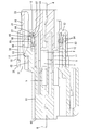
第1ハウジング10は合成樹脂製であって、図8及び図9に示すように、ブロック状のハウジング本体11と、ハウジング本体11の周りを取り囲む筒状の外側壁12と、外側壁12とハウジング本体11とをつなぐ径方向に沿った連結部13とを有している。ハウジング本体11と外側壁12との間で且つ連結部13の前方には、フード部62が嵌合される嵌合空間14が開放されている。つまり、フード部62は、ハウジング本体11に外嵌されるようになっている。連結部13は、後述するように、ハウジング本体11の外面に嵌着されたシールリング80が当て止めされる当て止め部となっている。
The
ハウジング本体11には、図8に示すように、複数のキャビティ15が形成されている。各キャビティ15には、後方から雌端子金具8が挿入されて収容される。図2に示すように、雌端子金具8は、電線4の端末部に圧着により接続され、前部に、第1、第2ハウジング10、60の嵌合に伴い雄タブ7が挿入されて接続される箱部9を有している。
As shown in FIG. 8, a plurality of
ハウジング本体11の上方には、図9に示すように、ロックアーム16が設けられている。
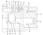
ロックアーム16は、図6及び図10に示すように、前後方向に延びる板状のアーム本体31と、アーム本体31の前後方向途中の幅方向両端部から側方に張り出して後述する保護壁34に一体に連結される一対の撓み支点部32とを備えている。アーム本体31は、撓み支点部32を支点としてその前後両端部を上下動させる向きに撓み変形可能とされている。そして、アーム本体31の後端部には、第1、第2ハウジング10、60の嵌合状態を解除する際に押圧される段状の解除操作部33が設けられている。
A
As shown in FIGS. 6 and 10, the
ロックアーム16の前端部には、ロック孔17が貫設されている。図2に示すように、第1、第2ハウジング10、60の正規嵌合時に、ロックアーム16のロック孔17にロック部63が弾性的に嵌まり込むことにより、第1、第2ハウジング10、60が嵌合状態に保持されるようになっている。なお、外側壁12の上壁には、ロックアーム16を視認可能な窓部18が開設されている。
A
また、図8及び図10に示すように、第1ハウジング10の幅方向両端部には、ロックアーム16を挟んだ両側に、一対の保護壁34が立設されている。両保護壁34は、上下方向に沿った縦壁状をなし、ハウジング本体11の前後方向の略全長に亘って形成されている。両保護壁34の後部は、ロックアーム16の両撓み支点部32に一体に連結されている。
Also, as shown in FIGS. 8 and 10, a pair of
また、第1ハウジング10には、ロックアーム16の前端部を上方から覆う覆い壁35が設けられている。覆い壁35は、幅方向に沿った平板状をなし、両保護壁34の前端上部に一体に連結されて両保護壁34間に幅方向に架け渡された形態とされている。
The
さらに、第1ハウジング10には、図10に示すように、ロックアーム16の幅方向両端部のうちロックアーム16の前端部から撓み支点部32の前端部に至るまでの部分を上方から覆う一対の庇壁36が設けられている。このため、ロックアーム16の前部の幅方向両端部と両保護壁34との間の隙間は、両庇壁36によって埋められる。
Furthermore, as shown in FIG. 10, the
両庇壁36は、覆い壁35と略面一で連なる平板状をなし、覆い壁35の後端及び両保護壁34の上端に一体に連なり、両保護壁34から幅方向内側に張り出す形態とされている。図10に示すように、両庇壁36と覆い壁35とは、平面視でU字形に連なり、その内側となる窓部18内に、ロック孔17が露出して配置されている。また、両庇壁36の後端には、前方へ向けて次第に近づく向きに傾斜する一対の斜縁部37が設けられている。
The both
また、第1ハウジング10の幅方向両端部には、図8に示すように、一対の抜け止め孔19が形成されている。図5に示すように、両抜け止め孔19は、外側壁12及び連結部13を貫通する形態とされ、内面後部に、前方を向いて径方向にほぼ沿って配置される当接受け面21を有しているとともに、内面前部に、後方を向いて径方向にほぼ沿って配置される係止受け面22を有している。
Moreover, as shown in FIG. 8, a pair of retaining
また、図9に示すように、第1ハウジング10の連結部13には、突部23が前方に突出して形成されている。図8に示すように、突部23は、連結部13における抜け止め孔19と対応する部位を除いた残余の領域に、ハウジング本体11の周りを取り囲むように周方向に広範囲に延在する形態とされている。突部23の内面、連結部13の前面及びハウジング本体11の外面によって区画される内側空間24(図9を参照)には、シールリング80の後述する後側のリング部87が嵌合可能とされている。ハウジング本体11の外面から連結部13の前面に連なる部位には、後側のリング部87の後述する案内面88と密着可能なテーパ状の傾斜面25が形成されている。
Further, as shown in FIG. 9, a
突部23の内面は、図3に示すように、ハウジング本体11の外面とほぼ平行に対向位置する規制面26とされている。突部23の規制面26は、後側のリング部87に外側から当接してこのリング部87のめくれ上がりを規制可能とされている。
As shown in FIG. 3, the inner surface of the projecting
突部23の外面は、外側壁12の内面と対向位置して、前方へ向けて次第に縮径するテーパ状の第1斜面27を有している。ハウジング本体11にフード部62が外嵌されると、突部23の第1斜面27とフード部62の第2斜面64とが互いに対面して配置されるようになっている。さらに、突部23の外面は、第1斜面27と段付き状に連なったあと連結部13側に向けて前後方向にほぼ沿って延びる水平面28を有している(図3を参照)。
The outer surface of the
シールリング80はシリコンゴム等のゴム製であって、図1及び図5に示すように、ハウジング本体11の外面に対応する環状のシール本体81と、シール本体81の幅方向両端部からいったん後方に突出したあと径方向外側に突出する抜け止め部82とを有している。
The
図7に示すように、シール本体81の前後方向途中部には、内周リップ83及び外周リップ84を有するシール部85が形成されている。内周リップ83は、シール部85の内面に周設された突条の形態とされ、前後の谷部間に配置されている。外周リップ84は、シール部85の外面に周設された突条の形態とされ、前後方向に2条並んで配置されている。この場合、両外周リップ84間の谷部は、内周リップ83と同じ前後位置に配置されている。図3に示すように、第1、第2ハウジング10、60が正規嵌合された状態では、内周リップ83がハウジング本体11の外面に弾性的に密着するとともに、両外周リップ84がフード部62の開口縁側の内面に弾性的に密着し、これによって第1、第2ハウジング10、60間が液密にシールされるようになっている。
As shown in FIG. 7, a
また、シール本体81は、シール部85を挟んだ前後両側となる前後方向両端部に、前後方向にほぼ沿った前後夫々のリング部86、87を有している。前後夫々のリング部86、87は、シール部85よりも薄肉であってリップを有さず、ハウジング本体11の外面及びフード部62の内面に平坦に密着するようになっている。そして、前後夫々のリング部86、87のうち、後側のリング部87は、前側のリング部86よりも前後方向に長尺とされている。また、図3に示すように、後側のリング部87の後端内周には、テーパ状の案内面88が切り欠き形成されている。
The
抜け止め部82は、図5に示すように、シール本体81側よりも厚肉の形態とされ、前端部の径方向外側に、断面略L字形の凹所91が切欠され、且つこの凹所91に、前方を向いて径方向にほぼ沿って配置される係止面92を有しているとともに、後端部の径方向内側に、後方を向いて径方向にほぼ沿って配置される当接面93を有している。係止面92は、後側のリング部87の後端面94と前後方向に関して同一位置に配置され、この係止面92と後側のリング部87の後端面94とにより規制される前後位置が第1ハウジング10成形時の金型のパーティングラインPLになっている。
As shown in FIG. 5, the retaining
次に、実施例1の防水コネクタの作用を説明する。
組み付けに際し、ハウジング本体11の外面に前方からシールリング80が装着される。シールリング80が正規装着されると、図5に示すように、両抜け止め部82が対応する抜け止め孔19に弾性的に嵌合されて、両抜け止め部82の当接面93が両抜け止め孔19の当接受け面21に当接してシールリング80のそれ以上の押し込みが規制され、且つ、両抜け止め部82の係止面92が両抜け止め孔19の係止受け面22に当接してシールリング80の前方への抜けが規制される。
Next, the effect | action of the waterproof connector of Example 1 is demonstrated.
At the time of assembly, the
また、両抜け止め部82の径方向外端が外側壁12の内面に弾性的に密着するとともに、両抜け止め部82の径方向内端がハウジング本体11の外面に弾性的に密着して、抜け止め部82が外側壁12とハウジング本体11との間に径方向に挟み込まれた状態となる。これにより、抜け止め部82が抜け止め孔19内に位置決め固定され、シールリング80が正規状態に保持される。
Further, the radially outer ends of both retaining
また、シールリング80がハウジング本体11に正規装着されると、図7に示すように、後側のリング部87が突部23とハウジング本体11との間の内側空間24に嵌合して挿入され、後側のリング部87の外面が突部23の規制面26と極僅かな隙間をあけた対向位置となる(図3を参照)。これにより、後側のリング部87が突部23とハウジング本体11との間に位置決め保持される。
Further, when the
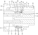
続いて、フード部62がハウジング本体11に外嵌されるようにして、第1、第2ハウジング10、60が互いに嵌合される。第1、第2ハウジング10、60の嵌合過程では、フード部62の第2斜面64が外周リップ84と摺接して、フード部62の押し込みとともにシールリング80に後方へのずれ力が作用する。この場合に、後側のリング部87が連結部13の前面に沿ってめくれ上がる懸念があるものの、実施例1によれば、後側のリング部87が突部23の規制面26に当接することにより、後側のリング部87がめくれたり座屈したりする事態が回避される。
Subsequently, the first and
第1、第2ハウジング10、60が正規嵌合されると、図4に示すように、ロックアーム16のロック孔17にロック部63が弾性的に嵌り込み、その状態を窓部18を通して視認することが可能となっている。
When the first and
また、第1、第2ハウジング10、60が正規嵌合されると、図3に示すように、フード部62の開口端側の内面にシールリング80の両外周リップ84が弾性的に密着するとともに、フード部62の開口縁部66が突部23に外側から覆い被さるように位置して、フード部62の第2斜面64が突部23の第1斜面27と近接しつつ対面位置する。
When the first and
図3に示すように、突部23にフード部62の開口縁部66が被さることにより、フード部62の開口端と連結部13の前面との間に前後方向の隙間50が形成されても、該隙間50の内奥には突部23が位置して、後側のリング部87が径方向外側に露出することはない。このため、例えば、高圧洗浄時において洗浄水が隙間50に浸入しても、突部23の第1斜面27が被水することにより、後側のリング部87が直接的に被水することはない。その結果、後側のリング部87に高い水圧が作用することはなく、後側のリング部87が水圧によって変形する事態が防止される。
As shown in FIG. 3, even if a
また、ロックアーム16と両保護壁34との間のクリアランスが両庇壁36によって埋められることにより、上方から見ると、シールリング80がロックアーム16のアーム本体31と両庇壁36とにより覆い隠されるため、シールリング80に高圧の洗浄水が直接かかることはない。このため、シールリング80が変形する事態がより確実に防止される。
In addition, since the clearance between the
しかも、ロックアーム16の前部周縁が覆い壁35と両庇壁36とによって覆われているため、例えば、後方からU字状に屈曲した電線4がロックアーム16の前側に回り込もうとしても、該電線4が両庇壁36に当接することにより、ロックアーム16の前端部に電線4が巻き込まれることはなく、ロックアーム16がめくれる事態が回避される。とくに、両庇壁36の後端が両斜縁部37によって逃がされた形態になっているため、電線4が両庇壁36に引っ掛かることも回避可能となる。
Moreover, since the front peripheral edge of the
以上説明したように、実施例1によれば、第1ハウジング10の突部23がハウジング本体11との間に後側のリング部87を径方向に挟み込むから、フード部62の進行に伴って後側のリング部87がめくれたり座屈したりする事態が回避される。また、ハウジング本体11にフード部62が外嵌されると、突部23にフード部62の開口縁部66が被さるから、高圧洗浄時に後側のリング部87が直接的に被水することがなく、後側のリング部87が高圧水によって変形するのが防止される。したがって、実施例1によれば、シールリング80のシール性能が良好に発揮される。とりわけ、実施例1の場合、金型のパーティングラインPLが抜け止め部82の係止面92と後側のリング部87の後端面94とで規定されるため、後側のリング部87が前側のリング部86より前後方向に長くなり易いという事情があるため、後側のリング部87のめくれや座屈を突部23によって回避することができるメリットは大きい。
As described above, according to the first embodiment, the
また、実施例1によれば、コネクタ低背化の要請等により、覆い壁35が薄肉とされても、一対の庇壁36が覆い壁35及び両保護壁34に一体に連結された形態で設けられているため、覆い壁35が庇壁36によって補強され、所定の強度を維持することができる。しかも、両庇壁36がロックアーム16の前端部から撓み支点部32側に延びてロックアーム16の幅方向両端部を覆う形態とされているため、ロックアーム16が電線4等の巻き込みに起因してめくれ上がる事態が回避される。したがって、両庇壁36が設けられても、コネクタの構成が無用に複雑になることはない。
In addition, according to the first embodiment, even if the
また、両庇壁36は、ロックアーム16の幅方向両端部のうち、ロックアーム16の前端部からロックアーム16の撓み支点部32に至る範囲を全体的に覆うように配置されているため、ロックアーム16がより確実に保護される。
Further, the both
しかも、両庇壁36はロックアーム16のロック孔17を覆わない位置に配置されているため、第1、第2ハウジング10、60の嵌合時に、ロック部63がロック孔17に嵌り込んだ状態を視認することができ、第1、第2ハウジング10、60が嵌合状態にあることを検知することができる。
Moreover, since the both
さらに、シールリング80が上方から見てロックアーム16と両庇壁36とによって覆い隠されているため、例えば、高圧洗浄時に、シールリング80が被水するのが回避され、高圧水によってシールリング80が変形するのが防止される。その結果、シールリング80による所定のシール性が保たれる。
Further, since the
<他の実施例>
本発明は上記記述及び図面によって説明した実施例に限定されるものではなく、例えば次のような態様も本発明の技術的範囲に含まれる。
(1)シールリングがハウジングに正規装着された場合に、後側のリング部の外面が突部の規制面に当接する構成であってもよい。
(2)シールリングのシール部から内周リップを省略してシール部の内面を平坦に形成してもよい。
(3)第1斜面、第2斜面及び傾斜面の少なくとも1つを省略して前後方向に沿ったストレート面としてもよい。
(4)第2ハウジングがプリント回路基板に実装される基板用のハウジングとされ、雄端子金具が基板に半田接続可能なピン状の形態とされるものであってもよい。
(5)シールリングから抜け止め部を省略することも可能である。その場合、ハウジング本体に前方から装着されるフロント部材の周壁によってシールリングの抜け止めを行えばよい。
(6)両庇壁は、ロックアームの幅方向両端部のうち、ロックアームの前端部から撓み支点部の前端に至るまでの範囲を覆う形態であってもよい。
(7)両庇壁は、ロックアームの幅方向両端部のうち、ロックアームの前端部から撓み支点部の後端を越えてさらに後方の範囲を覆う形態であってもよい。
<Other embodiments>
The present invention is not limited to the embodiments described with reference to the above description and drawings. For example, the following aspects are also included in the technical scope of the present invention.
(1) When the seal ring is properly attached to the housing, the outer surface of the rear ring portion may be in contact with the regulating surface of the protrusion.
(2) The inner peripheral lip may be omitted from the seal portion of the seal ring, and the inner surface of the seal portion may be formed flat.
(3) It is good also as a straight surface along the front-back direction, omitting at least one of the first inclined surface, the second inclined surface, and the inclined surface.
(4) The second housing may be a board housing mounted on the printed circuit board, and the male terminal fitting may be in a pin-like form that can be soldered to the board.
(5) The retaining portion can be omitted from the seal ring. In that case, the seal ring may be prevented from coming off by the peripheral wall of the front member attached to the housing body from the front.
(6) A form which covers the range from the front-end part of a lock arm to the front end of a bending fulcrum part among the both ends of the width direction of a lock arm may be sufficient as a both rib wall.
(7) The both side walls may be configured such that, of both ends in the width direction of the lock arm, the range beyond the rear end of the bending fulcrum from the front end of the lock arm is covered.
10…第1ハウジング
11…ハウジング本体
12…外側壁
13…連結部(当て止め部)
16…ロックアーム
17…ロック孔
22…係止受け面
23…突部
31…アーム本体
32…撓み支点部
34…保護壁
35…覆い壁
36…庇壁
60…第2ハウジング
62…フード部
63…ロック部
66…開口縁部
80…シールリング
81…シール本体
82…抜け止め部
84…外周リップ(リップ)
85…シール部
86…前側のリング部
87…後側のリング部
92…係止面
PL…パーティングライン
DESCRIPTION OF
DESCRIPTION OF
85 ... Sealing
Claims (4)
前記第1ハウジングには、前記第2ハウジングとの嵌合時に前記第2ハウジングのロック部を弾性的に係止して第1、第2ハウジングを嵌合状態に保持するロックアームが撓み可能に設けられるとともに、前記ロックアームを挟んだ両側に一対の保護壁が立設され、且つ、前記ロックアームの先端部を覆う覆い壁が架設されており、さらに、
前記第1ハウジングには、前記覆い壁及び前記両保護壁に一体に連結されて前記ロックアームの先端部から撓み支点部側に延びて前記ロックアームの幅方向両端部を覆う一対の庇壁が突設されていることを特徴とするコネクタ。 A first housing that can be fitted with the second housing;
The first housing can be flexed with a lock arm that elastically locks the lock portion of the second housing and holds the first and second housings in a fitted state when fitted to the second housing. And a pair of protective walls are erected on both sides of the lock arm, and a cover wall that covers the tip of the lock arm is constructed,
The first housing has a pair of ridge walls that are integrally connected to the cover wall and the two protection walls, extend from the distal end portion of the lock arm toward the fulcrum fulcrum, and cover both ends in the width direction of the lock arm. A connector characterized by being protruded.
前記シールリングは、前記ロックアームの位置する側において、前記ロックアームと前記両庇壁とにより覆い隠されていることを特徴とする請求項1ないし3のいずれか1項記載のコネクタ。 The first housing has a housing main body to which a hood portion of the second housing can be fitted, and the housing main body is interposed between the housing main body and the hood portion when fitted to the second housing. A seal ring that is elastically sandwiched between the first and second housings to provide a liquid-tight seal is provided;
The connector according to any one of claims 1 to 3, wherein the seal ring is covered and hidden by the lock arm and both side walls on the side where the lock arm is located.
Priority Applications (2)
| Application Number | Priority Date | Filing Date | Title |
|---|---|---|---|
| JP2013014093A JP5874655B2 (en) | 2013-01-29 | 2013-01-29 | connector |
| PCT/JP2014/051485 WO2014119480A1 (en) | 2013-01-29 | 2014-01-24 | Connector |
Applications Claiming Priority (1)
| Application Number | Priority Date | Filing Date | Title |
|---|---|---|---|
| JP2013014093A JP5874655B2 (en) | 2013-01-29 | 2013-01-29 | connector |
Publications (2)
| Publication Number | Publication Date |
|---|---|
| JP2014146491A true JP2014146491A (en) | 2014-08-14 |
| JP5874655B2 JP5874655B2 (en) | 2016-03-02 |
Family
ID=51262194
Family Applications (1)
| Application Number | Title | Priority Date | Filing Date |
|---|---|---|---|
| JP2013014093A Active JP5874655B2 (en) | 2013-01-29 | 2013-01-29 | connector |
Country Status (2)
| Country | Link |
|---|---|
| JP (1) | JP5874655B2 (en) |
| WO (1) | WO2014119480A1 (en) |
Cited By (3)
| Publication number | Priority date | Publication date | Assignee | Title |
|---|---|---|---|---|
| JP2016066474A (en) * | 2014-09-24 | 2016-04-28 | 矢崎総業株式会社 | Connector housing |
| JP2021168236A (en) * | 2020-04-09 | 2021-10-21 | 矢崎総業株式会社 | Connector unit and connector |
| JP2021168235A (en) * | 2020-04-09 | 2021-10-21 | 矢崎総業株式会社 | connector |
Families Citing this family (2)
| Publication number | Priority date | Publication date | Assignee | Title |
|---|---|---|---|---|
| JP6488978B2 (en) * | 2015-10-08 | 2019-03-27 | 住友電装株式会社 | Waterproof connector |
| JP7116896B2 (en) * | 2019-05-31 | 2022-08-12 | 住友電装株式会社 | connector |
Citations (5)
| Publication number | Priority date | Publication date | Assignee | Title |
|---|---|---|---|---|
| JPH01119180U (en) * | 1988-02-08 | 1989-08-11 | ||
| JPH0745334A (en) * | 1993-07-28 | 1995-02-14 | Sumitomo Wiring Syst Ltd | Connector |
| JP2002252063A (en) * | 2001-02-26 | 2002-09-06 | Jst Mfg Co Ltd | Connector assembly with lock mechanism |
| JP2011018617A (en) * | 2009-07-10 | 2011-01-27 | Sumitomo Wiring Syst Ltd | Connector |
| JP2011243480A (en) * | 2010-05-20 | 2011-12-01 | Sumitomo Wiring Syst Ltd | Connector |
-
2013
- 2013-01-29 JP JP2013014093A patent/JP5874655B2/en active Active
-
2014
- 2014-01-24 WO PCT/JP2014/051485 patent/WO2014119480A1/en active Application Filing
Patent Citations (5)
| Publication number | Priority date | Publication date | Assignee | Title |
|---|---|---|---|---|
| JPH01119180U (en) * | 1988-02-08 | 1989-08-11 | ||
| JPH0745334A (en) * | 1993-07-28 | 1995-02-14 | Sumitomo Wiring Syst Ltd | Connector |
| JP2002252063A (en) * | 2001-02-26 | 2002-09-06 | Jst Mfg Co Ltd | Connector assembly with lock mechanism |
| JP2011018617A (en) * | 2009-07-10 | 2011-01-27 | Sumitomo Wiring Syst Ltd | Connector |
| JP2011243480A (en) * | 2010-05-20 | 2011-12-01 | Sumitomo Wiring Syst Ltd | Connector |
Cited By (3)
| Publication number | Priority date | Publication date | Assignee | Title |
|---|---|---|---|---|
| JP2016066474A (en) * | 2014-09-24 | 2016-04-28 | 矢崎総業株式会社 | Connector housing |
| JP2021168236A (en) * | 2020-04-09 | 2021-10-21 | 矢崎総業株式会社 | Connector unit and connector |
| JP2021168235A (en) * | 2020-04-09 | 2021-10-21 | 矢崎総業株式会社 | connector |
Also Published As
| Publication number | Publication date |
|---|---|
| WO2014119480A1 (en) | 2014-08-07 |
| JP5874655B2 (en) | 2016-03-02 |
Similar Documents
| Publication | Publication Date | Title |
|---|---|---|
| JP5796799B2 (en) | Waterproof connector | |
| JP5874655B2 (en) | connector | |
| US8449323B2 (en) | Watertight shield connector | |
| JP5874977B2 (en) | Grommet and mounting member with grommet | |
| JP4463665B2 (en) | Waterproof connector | |
| KR102130237B1 (en) | Waterproof connector | |
| JP5476999B2 (en) | connector | |
| JPH1174025A (en) | Connector | |
| JP5729350B2 (en) | Waterproof connector | |
| JP5173485B2 (en) | Waterproof electrical connector | |
| JP2013098072A (en) | Waterproof connector | |
| WO2013128848A1 (en) | Waterproof connector | |
| US9099812B2 (en) | Connector | |
| JP5565054B2 (en) | connector | |
| CN111628364B (en) | Connector with a locking member | |
| JP6422696B2 (en) | Electrical junction box | |
| JP2020198256A (en) | housing | |
| JP6438675B2 (en) | Connector waterproof structure | |
| JP5890985B2 (en) | Connector and covering member used for this connector | |
| JP5818101B2 (en) | Waterproof connector | |
| JP2006252888A (en) | Connector and protection plug | |
| US20230122279A1 (en) | Connector | |
| CN107039833B (en) | Connector and cap | |
| JP2012252973A (en) | Connector | |
| JP2014120352A (en) | Waterproof connector |
Legal Events
| Date | Code | Title | Description |
|---|---|---|---|
| A621 | Written request for application examination |
Free format text: JAPANESE INTERMEDIATE CODE: A621 Effective date: 20150730 |
|
| A871 | Explanation of circumstances concerning accelerated examination |
Free format text: JAPANESE INTERMEDIATE CODE: A871 Effective date: 20150903 |
|
| A975 | Report on accelerated examination |
Free format text: JAPANESE INTERMEDIATE CODE: A971005 Effective date: 20151009 |
|
| A131 | Notification of reasons for refusal |
Free format text: JAPANESE INTERMEDIATE CODE: A131 Effective date: 20151023 |
|
| A521 | Written amendment |
Free format text: JAPANESE INTERMEDIATE CODE: A523 Effective date: 20151204 |
|
| TRDD | Decision of grant or rejection written | ||
| A01 | Written decision to grant a patent or to grant a registration (utility model) |
Free format text: JAPANESE INTERMEDIATE CODE: A01 Effective date: 20151222 |
|
| A61 | First payment of annual fees (during grant procedure) |
Free format text: JAPANESE INTERMEDIATE CODE: A61 Effective date: 20160104 |
|
| R150 | Certificate of patent or registration of utility model |
Ref document number: 5874655 Country of ref document: JP Free format text: JAPANESE INTERMEDIATE CODE: R150 |