JP2014145942A - Optical scanning observation device - Google Patents
Optical scanning observation device Download PDFInfo
- Publication number
- JP2014145942A JP2014145942A JP2013014819A JP2013014819A JP2014145942A JP 2014145942 A JP2014145942 A JP 2014145942A JP 2013014819 A JP2013014819 A JP 2013014819A JP 2013014819 A JP2013014819 A JP 2013014819A JP 2014145942 A JP2014145942 A JP 2014145942A
- Authority
- JP
- Japan
- Prior art keywords
- optical scanning
- frequency
- observation apparatus
- optical fiber
- scanning observation
- Prior art date
- Legal status (The legal status is an assumption and is not a legal conclusion. Google has not performed a legal analysis and makes no representation as to the accuracy of the status listed.)
- Pending
Links
- 230000003287 optical effect Effects 0.000 title claims abstract description 55
- 239000013307 optical fiber Substances 0.000 claims abstract description 58
- 238000001514 detection method Methods 0.000 claims description 45
- VYPSYNLAJGMNEJ-UHFFFAOYSA-N silicon dioxide Inorganic materials O=[Si]=O VYPSYNLAJGMNEJ-UHFFFAOYSA-N 0.000 claims description 33
- 239000010453 quartz Substances 0.000 claims description 30
- 239000011347 resin Substances 0.000 claims description 11
- 229920005989 resin Polymers 0.000 claims description 11
- 239000011248 coating agent Substances 0.000 claims description 10
- 238000000576 coating method Methods 0.000 claims description 10
- 229920001721 polyimide Polymers 0.000 claims description 9
- 239000009719 polyimide resin Substances 0.000 claims description 9
- 229920002530 polyetherether ketone Polymers 0.000 claims description 8
- 239000004925 Acrylic resin Substances 0.000 claims description 7
- 230000001681 protective effect Effects 0.000 claims description 6
- NIXOWILDQLNWCW-UHFFFAOYSA-M Acrylate Chemical compound [O-]C(=O)C=C NIXOWILDQLNWCW-UHFFFAOYSA-M 0.000 claims description 2
- 230000003993 interaction Effects 0.000 claims description 2
- 230000008859 change Effects 0.000 abstract description 15
- 230000010355 oscillation Effects 0.000 abstract description 3
- 238000005286 illumination Methods 0.000 description 23
- 238000000034 method Methods 0.000 description 10
- 238000003780 insertion Methods 0.000 description 9
- 230000037431 insertion Effects 0.000 description 9
- 230000008569 process Effects 0.000 description 9
- 230000005855 radiation Effects 0.000 description 8
- 238000010586 diagram Methods 0.000 description 4
- RTZKZFJDLAIYFH-UHFFFAOYSA-N Diethyl ether Chemical compound CCOCC RTZKZFJDLAIYFH-UHFFFAOYSA-N 0.000 description 2
- 230000006866 deterioration Effects 0.000 description 2
- 239000000835 fiber Substances 0.000 description 2
- 230000006870 function Effects 0.000 description 2
- 125000002887 hydroxy group Chemical group [H]O* 0.000 description 2
- 238000012986 modification Methods 0.000 description 2
- 230000004048 modification Effects 0.000 description 2
- FOXXZZGDIAQPQI-XKNYDFJKSA-N Asp-Pro-Ser-Ser Chemical compound OC(=O)C[C@H](N)C(=O)N1CCC[C@H]1C(=O)N[C@@H](CO)C(=O)N[C@@H](CO)C(O)=O FOXXZZGDIAQPQI-XKNYDFJKSA-N 0.000 description 1
- 239000003086 colorant Substances 0.000 description 1
- 230000007423 decrease Effects 0.000 description 1
- 230000005284 excitation Effects 0.000 description 1
- 230000001678 irradiating effect Effects 0.000 description 1
- 150000002576 ketones Chemical class 0.000 description 1
- 230000000644 propagated effect Effects 0.000 description 1
- 239000004065 semiconductor Substances 0.000 description 1
- 230000003595 spectral effect Effects 0.000 description 1
Images


Classifications
-
- G—PHYSICS
- G02—OPTICS
- G02B—OPTICAL ELEMENTS, SYSTEMS OR APPARATUS
- G02B26/00—Optical devices or arrangements for the control of light using movable or deformable optical elements
- G02B26/08—Optical devices or arrangements for the control of light using movable or deformable optical elements for controlling the direction of light
- G02B26/10—Scanning systems
- G02B26/103—Scanning systems having movable or deformable optical fibres, light guides or waveguides as scanning elements
-
- G—PHYSICS
- G02—OPTICS
- G02B—OPTICAL ELEMENTS, SYSTEMS OR APPARATUS
- G02B23/00—Telescopes, e.g. binoculars; Periscopes; Instruments for viewing the inside of hollow bodies; Viewfinders; Optical aiming or sighting devices
- G02B23/24—Instruments or systems for viewing the inside of hollow bodies, e.g. fibrescopes
- G02B23/26—Instruments or systems for viewing the inside of hollow bodies, e.g. fibrescopes using light guides
-
- A—HUMAN NECESSITIES
- A61—MEDICAL OR VETERINARY SCIENCE; HYGIENE
- A61B—DIAGNOSIS; SURGERY; IDENTIFICATION
- A61B1/00—Instruments for performing medical examinations of the interior of cavities or tubes of the body by visual or photographical inspection, e.g. endoscopes; Illuminating arrangements therefor
- A61B1/00002—Operational features of endoscopes
- A61B1/00004—Operational features of endoscopes characterised by electronic signal processing
- A61B1/00006—Operational features of endoscopes characterised by electronic signal processing of control signals
-
- A—HUMAN NECESSITIES
- A61—MEDICAL OR VETERINARY SCIENCE; HYGIENE
- A61B—DIAGNOSIS; SURGERY; IDENTIFICATION
- A61B1/00—Instruments for performing medical examinations of the interior of cavities or tubes of the body by visual or photographical inspection, e.g. endoscopes; Illuminating arrangements therefor
- A61B1/00002—Operational features of endoscopes
- A61B1/00057—Operational features of endoscopes provided with means for testing or calibration
-
- A—HUMAN NECESSITIES
- A61—MEDICAL OR VETERINARY SCIENCE; HYGIENE
- A61B—DIAGNOSIS; SURGERY; IDENTIFICATION
- A61B1/00—Instruments for performing medical examinations of the interior of cavities or tubes of the body by visual or photographical inspection, e.g. endoscopes; Illuminating arrangements therefor
- A61B1/00064—Constructional details of the endoscope body
-
- A—HUMAN NECESSITIES
- A61—MEDICAL OR VETERINARY SCIENCE; HYGIENE
- A61B—DIAGNOSIS; SURGERY; IDENTIFICATION
- A61B1/00—Instruments for performing medical examinations of the interior of cavities or tubes of the body by visual or photographical inspection, e.g. endoscopes; Illuminating arrangements therefor
- A61B1/00163—Optical arrangements
- A61B1/00165—Optical arrangements with light-conductive means, e.g. fibre optics
- A61B1/00167—Details of optical fibre bundles, e.g. shape or fibre distribution
-
- A—HUMAN NECESSITIES
- A61—MEDICAL OR VETERINARY SCIENCE; HYGIENE
- A61B—DIAGNOSIS; SURGERY; IDENTIFICATION
- A61B1/00—Instruments for performing medical examinations of the interior of cavities or tubes of the body by visual or photographical inspection, e.g. endoscopes; Illuminating arrangements therefor
- A61B1/00163—Optical arrangements
- A61B1/00172—Optical arrangements with means for scanning
-
- A—HUMAN NECESSITIES
- A61—MEDICAL OR VETERINARY SCIENCE; HYGIENE
- A61B—DIAGNOSIS; SURGERY; IDENTIFICATION
- A61B1/00—Instruments for performing medical examinations of the interior of cavities or tubes of the body by visual or photographical inspection, e.g. endoscopes; Illuminating arrangements therefor
- A61B1/06—Instruments for performing medical examinations of the interior of cavities or tubes of the body by visual or photographical inspection, e.g. endoscopes; Illuminating arrangements therefor with illuminating arrangements
- A61B1/07—Instruments for performing medical examinations of the interior of cavities or tubes of the body by visual or photographical inspection, e.g. endoscopes; Illuminating arrangements therefor with illuminating arrangements using light-conductive means, e.g. optical fibres
-
- G—PHYSICS
- G02—OPTICS
- G02B—OPTICAL ELEMENTS, SYSTEMS OR APPARATUS
- G02B23/00—Telescopes, e.g. binoculars; Periscopes; Instruments for viewing the inside of hollow bodies; Viewfinders; Optical aiming or sighting devices
- G02B23/24—Instruments or systems for viewing the inside of hollow bodies, e.g. fibrescopes
- G02B23/2407—Optical details
- G02B23/2461—Illumination
- G02B23/2469—Illumination using optical fibres
-
- G—PHYSICS
- G02—OPTICS
- G02B—OPTICAL ELEMENTS, SYSTEMS OR APPARATUS
- G02B6/00—Light guides; Structural details of arrangements comprising light guides and other optical elements, e.g. couplings
- G02B6/02—Optical fibres with cladding with or without a coating
- G02B6/02033—Core or cladding made from organic material, e.g. polymeric material
-
- G—PHYSICS
- G02—OPTICS
- G02B—OPTICAL ELEMENTS, SYSTEMS OR APPARATUS
- G02B6/00—Light guides; Structural details of arrangements comprising light guides and other optical elements, e.g. couplings
- G02B6/02—Optical fibres with cladding with or without a coating
- G02B6/036—Optical fibres with cladding with or without a coating core or cladding comprising multiple layers
-
- G—PHYSICS
- G02—OPTICS
- G02B—OPTICAL ELEMENTS, SYSTEMS OR APPARATUS
- G02B6/00—Light guides; Structural details of arrangements comprising light guides and other optical elements, e.g. couplings
- G02B6/44—Mechanical structures for providing tensile strength and external protection for fibres, e.g. optical transmission cables
- G02B6/4401—Optical cables
- G02B6/4429—Means specially adapted for strengthening or protecting the cables
- G02B6/443—Protective covering
Abstract
Description
本発明は、周囲の温度変化に対して画角の変動を抑制可能な光走査型観察装置に関するものである。 The present invention relates to an optical scanning observation apparatus that can suppress a change in angle of view with respect to a change in ambient temperature.
照射光を出射する光ファイバを振動させることにより被観察物を走査し、被観察物の画像を取得する光走査型観察装置が知られている。観察に適した画像を取得するためには、光ファイバを所定の振動経路に沿って振動させる必要がある。 2. Description of the Related Art There is known an optical scanning observation apparatus that scans an object to be observed by vibrating an optical fiber that emits irradiation light and acquires an image of the object to be observed. In order to acquire an image suitable for observation, it is necessary to vibrate the optical fiber along a predetermined vibration path.
光走査型観察装置は、例えば工業用内視鏡などのように多様な外部環境において使用されるものがある。外部環境によっては、光ファイバが所定の振動経路から外れることがあり、取得する画像に歪みなどが生じ得る。 Some optical scanning observation apparatuses are used in various external environments such as an industrial endoscope. Depending on the external environment, the optical fiber may deviate from the predetermined vibration path, and distortion or the like may occur in the acquired image.
そこで、高温下における歪みを有する画像に対して、リマッピングを施すことにより歪みを低減化する内視鏡装置が提案されている(特許文献1参照)。 Therefore, an endoscope apparatus has been proposed that reduces distortion by performing remapping on an image having distortion at high temperatures (see Patent Document 1).
温度などの外部環境の変化は歪みを生じさせるのみならず、画角に変動を生じさせ得る。特許文献1に記載の内視鏡装置では、温度変化により生じ得る画像の歪みを修正することが出来るが、画角の変動には対処できなかった。
Changes in the external environment such as temperature can cause distortion as well as fluctuations in the angle of view. The endoscope apparatus described in
本発明は、かかる観点に鑑みてなされたもので、外部環境の変化に対して画角の変動を抑制可能な光走査型観察装置を提供することを目的とするものである。 The present invention has been made in view of such a viewpoint, and an object of the present invention is to provide an optical scanning observation apparatus capable of suppressing a change in the angle of view with respect to a change in the external environment.
上述した諸課題を解決すべく、第1の観点による光走査型観察装置は、
一端が揺動可能に支持される揺動部を有する光ファイバと、
前記揺動部を、駆動信号に基づいて振動させる振動駆動手段と、
前記振動駆動手段に送信する前記駆動信号の周波数を変更する変更手段とを備える
を備えることを特徴とするものである。
In order to solve the above-described problems, the optical scanning observation apparatus according to the first aspect is
An optical fiber having a swinging portion whose one end is swingably supported;
Vibration drive means for vibrating the rocking portion based on a drive signal;
And a change means for changing the frequency of the drive signal transmitted to the vibration drive means.
また、第2の観点による光走査型観察装置において、
前記揺動部近傍の温度を検出する温度センサを、さらに備え、
前記変更手段は、前記温度センサが検出した温度に基づいて、前記駆動信号の周波数を変更する
ことが好ましい。
In the optical scanning observation apparatus according to the second aspect,
A temperature sensor for detecting the temperature in the vicinity of the swinging portion,
The changing means preferably changes the frequency of the drive signal based on the temperature detected by the temperature sensor.
また、第3の観点による光走査型観察装置において、
前記揺動部近傍の温度に対する周波数の対応を記憶する記憶手段を、さらに備え、
前記変更手段は、前記温度センサが検出した温度に対応する周波数を前記記憶手段から読出し、該周波数に前記駆動信号の周波数を合わせる
ことが好ましい。
In the optical scanning observation apparatus according to the third aspect,
Storage means for storing the correspondence of the frequency to the temperature in the vicinity of the oscillating portion;
Preferably, the changing unit reads a frequency corresponding to the temperature detected by the temperature sensor from the storage unit, and matches the frequency of the drive signal to the frequency.
また、第4の観点による光走査型観察装置において、
前記光ファイバは、純粋石英、フッ素添加石英、および水酸基添加石英の少なくとも一つを含むコアと、純粋石英、フッ素添加石英、および水酸基添加石英の少なくとも一つを含むクラッドと、ポリイミド樹脂、ポリエチルエーテルケトン樹脂、およびアクリレート樹脂の少なくとも一つを含む被覆と、ポリイミド樹脂、ポリエチルエーテルケトン樹脂、およびアクリレート樹脂の少なくとも一つを含む保護ジャケットとを有する
ことが好ましい。
In the optical scanning observation apparatus according to the fourth aspect,
The optical fiber includes a core including at least one of pure quartz, fluorine-added quartz, and hydroxyl-added quartz, a clad including at least one of pure quartz, fluorine-added quartz, and hydroxyl-added quartz, polyimide resin, and polyethyl ether. It is preferable to have a coating containing at least one of a ketone resin and an acrylate resin, and a protective jacket containing at least one of a polyimide resin, a polyethyl ether ketone resin, and an acrylate resin.
また、第5の観点による光走査型観察装置において、
純粋石英、フッ素添加石英、および水酸基添加石英の少なくとも一つを含むコアと、純粋石英、フッ素添加石英、および水酸基添加石英の少なくとも一つを含むクラッドと、ポリイミド樹脂、ポリエチルエーテルケトン樹脂、およびアクリレート樹脂の少なくとも一つを含む被覆と、ポリイミド樹脂、ポリエチルエーテルケトン樹脂、およびアクリレート樹脂の少なくとも一つを含む保護ジャケットとを有し、
前記揺動部から出射する光と被観察物との相互作用による光を伝播する検出用光ファイバを、さらに備える
ことが好ましい。
In the optical scanning observation apparatus according to the fifth aspect,
A core including at least one of pure quartz, fluorine-added quartz, and hydroxyl-added quartz; a clad including at least one of pure quartz, fluorine-added quartz, and hydroxyl-added quartz; polyimide resin, polyethyl ether ketone resin, and acrylate A coating including at least one of a resin and a protective jacket including at least one of a polyimide resin, a polyethyl ether ketone resin, and an acrylate resin;
It is preferable to further include a detection optical fiber that propagates light generated by the interaction between the light emitted from the rocking portion and the object to be observed.
本発明によれば、光走査型観察装置において、外部環境の変化に対して画角の変動を抑制可能である。 According to the present invention, in the optical scanning observation apparatus, it is possible to suppress changes in the angle of view with respect to changes in the external environment.
以下、本発明の実施の形態について、図を参照して説明する。 Hereinafter, embodiments of the present invention will be described with reference to the drawings.
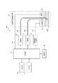
図1は、本発明の第1の実施形態に係る光走査型観察装置の内部構成を概略的に示す機能ブロック図である。 FIG. 1 is a functional block diagram schematically showing the internal configuration of the optical scanning observation apparatus according to the first embodiment of the present invention.
光走査型観察装置10は、例えば、光走査型内視鏡装置であり、光源部11、光走査型内視鏡本体12、検出部13、駆動電流生成部14、制御部15、表示部16、入力部17、および記憶部18を含んで構成される。
The optical
光源部11と光走査型内視鏡本体12との間はシングルモードファイバである照明用光ファイバ19により光学的に接続され、検出部13と光走査型内視鏡本体12との間はマルチモードファイバにより構成される検出用光ファイババンドル20により光学的に接続されている。なお、光源部11、検出部13、駆動電流生成部14、制御部15、および記憶部18は、同一の筐体内に収納されていてもよく、また、別々の筐体に収納されていてもよい。
The light source unit 11 and the optical scanning endoscope
光源部11は、例えば赤、緑および青の三原色のCW(連続発振)レーザ光を射出する3つのレーザ光源からの光を合波して白色光として出射する。レーザ光源としては、例えばDPSSレーザ(半導体励起固体レーザ)やレーザダイオードを使用することができる。もちろん、光源部11の構成はこれに限られず、一つのレーザ光源を用いるものであっても、他の複数の光源を用いるものであってもよい。 The light source unit 11 combines, for example, light from three laser light sources that emit CW (continuous oscillation) laser lights of three primary colors of red, green, and blue, and emits them as white light. As the laser light source, for example, a DPSS laser (semiconductor excitation solid-state laser) or a laser diode can be used. Of course, the configuration of the light source unit 11 is not limited to this, and a single laser light source may be used, or a plurality of other light sources may be used.
光走査型内視鏡本体12は、照明用光ファイバ19により光源部11から出射され光を、走査部21(振動駆動手段)により被観察物obj上で走査して、この走査により得られた信号光を集光し、検出用光ファイババンドル20を介して検出部13に伝送する。
The optical scanning endoscope
検出部13は、検出用光ファイババンドル20を伝播した信号光をスペクトル成分に分解し、光電子増倍管またはフォトダイオードなどを用いた光検出器により、信号光を電気信号に変換する。
The
駆動電流生成部14(振動駆動手段)は、制御部15からの制御に基づいて、走査部21に対して配線ケーブル22を介して振動電流を駆動信号として印加する。
The drive current generation unit 14 (vibration drive unit) applies the vibration current as a drive signal to the
制御部15(変更手段)は、光源部11、検出部13、および駆動電流生成部14を同期制御するとともに、検出部13により出力された電気信号を処理して、画像を合成し表示部16に表示する。また、制御部15は、入力部17から、光走査型観察装置10に、走査速度や表示画像の明るさ等、種々の設定を行うことができる。また、制御部15は、後述するように、光走査型内視鏡本体12に設けられる温度センサ23から配線ケーブル24を介して温度を取得し、取得した温度に基づいて駆動信号の周波数を決定し、駆動電流生成部14に駆動信号の周波数を変更させる。
The control unit 15 (changing unit) synchronously controls the light source unit 11, the
記憶部18は、例えばROMであって、予め定められている情報を記憶する。例えば、記憶部18は、駆動信号の周波数変更に用いる、温度に対する周波数の対応表を記憶する。
The
図2は、光走査型内視鏡本体12を概略的に示す概観図である。光走査型内視鏡本体12は、操作部25および挿入部26を備え、操作部25の一方の端部と挿入部26の基端部とは接続されて一体となっている。
FIG. 2 is a schematic view schematically showing the optical scanning endoscope
操作部25には、光源部11からの照明用光ファイバ19、検出部13からの検出用光ファイババンドル20、駆動電流生成部14からの配線ケーブル22、および制御部15からの配線ケーブル24が、それぞれ接続されている。これら照明用光ファイバ19、検出用光ファイババンドル20、配線ケーブル22、および配線ケーブル24は挿入部26内部を通じて、挿入部26の先端部27(図2における破線部内の部分)まで導かれている。
The
図3は、図2の光走査型内視鏡本体12の先端部27を拡大して示す断面図である。先端部27は、走査部21、温度センサ23、投影用レンズ28a、28bおよび図示しない検出用レンズを備えるとともに、挿入部26を通る照明用光ファイバ19および検出用光ファイババンドル20が延在している。
3 is an enlarged cross-sectional view of the
走査部21は、角型チューブ29、偏向磁場発生用コイル30a〜30d、および永久磁石31(図4参照)を含んで構成される。
The
角型チューブ29は中空の四角柱形状であり、一端が閉鎖され、他端が開放されている。角型チューブ29は、取付環32により先端部27内部に、先端部27の中心軸線に長手方向が一致し且つ開放された端部が先端部27の先端側を向くように固定される(図3参照)。本実施形態においては、四角柱形状の角型チューブ29を適用するが、円筒状および内部が中空である他の形状であってもよい。
The
偏向磁場発生用コイル30a〜30dは、角型チューブ29の各側面の長手方向における同じ位置に設けられる(図4参照)。偏向磁場発生用コイル30a、30cが互いに対向する側面に設けられ、偏向磁場発生用コイル30b、30dが互いに対向する側面に設けられる。偏向磁場発生用コイル30a、30cの中心を通る直線と、偏向磁場発生用コイル30b、30dの中心を通る直線とは、角型チューブ29の中心軸線付近で直交する。偏向磁場発生用コイル30a〜30dは、配線ケーブル22を介して駆動電流生成部14に接続される。偏向磁場発生用コイル30a、30cと偏向磁場発生用コイル30b、30dとには、駆動電流生成部14から独立して異なる周波数の電流が駆動信号として印加される。偏向磁場発生用コイル30a、30cに駆動信号を印加すると、偏向磁場発生用コイル30a、30c間に第1軸偏向磁場が発生する。偏向磁場発生用コイル30b、30dに駆動信号を印加すると、偏向磁場発生用コイル30b、30d間に第2軸偏向磁場が発生する。第1軸偏向磁場および第2軸偏向磁場により、後述する永久磁石31を有する揺動部19bが、各磁場強度に応じて第1軸偏向磁場および第2軸偏向磁場に対応する2方向に振動する。
The deflection magnetic
永久磁石31は円筒状であり、内部の貫通孔に照明用光ファイバ19を挿通させた状態で、照明用光ファイバ19と結合する。永久磁石31は、照明用光ファイバ19の軸方向に着磁される。
The
照明用光ファイバ19は、図5に示すように、コア33、クラッド34、および被覆35によって構成される。コア33は円柱状であり、クラッド34はコア33の周囲を覆う。被覆35は、さらにクラッド34の周囲を覆う。照明用光ファイバ19の全長の一部において、光ファイバ保護ジャケット36が、さらに被覆35の周囲を覆う。コア33は、純粋石英、フッ素添加石英、および水酸基添加石英の少なくとも一つを含み、高い耐熱性および耐放射線性を有する。クラッド34は、コア33より低屈折率な純粋石英、フッ素添加石英、および水酸基添加石英の少なくとも一つを含み、高い耐熱性および耐放射線性を有する。被覆35および光ファイバ保護ジャケット36は、ポリイミド樹脂、ポリエチルエーテルケトン樹脂、およびアクリレート樹脂の少なくとも一つを含み、高い耐熱性および耐放射線性を有する。
The illumination
照明用光ファイバ19は、角型チューブ29の閉鎖された端部に形成される孔部を挿通し、永久磁石31の一方の極が偏向磁場発生用コイル30a〜30dに挟まれるように、角型チューブ29の閉鎖された端部において支持される(図4参照)。したがって、照明用光ファイバ19は、角型チューブ29に支持された固定端19aから先端部19cまでが揺動可能である。照明用光ファイバ19の、永久磁石31を含めた固定端19aから先端部19cまでの部位を揺動部19bとする。
The illumination
検出用光ファイババンドル20は、複数の検出用光ファイバを束ねたバンドルである。各検出用光ファイバは、照明用光ファイバ19と同様の部材によって形成された、コア33、クラッド34、被覆35、光ファイバ保護ジャケット36によって構成される。したがって、検出用光ファイババンドル20は、照明用光ファイバ19と同様に、高い耐熱性および耐放射線性を有する。検出用光ファイババンドル20は、挿入部26の先端部27の外周を通るように配置され、先端部27の先端まで延びている。本実施形態においては、検出用光ファイババンドル20は先端部27の外周を通るような配置であるが、そのような構成に限定されず、例えば、束ねた状態で配置されていてもよい。
The detection
温度センサ23は、挿入部26先端部27内において揺動部19b近傍に固定される。温度センサ23は、例えば熱電対またはサーミスタであり、揺動部19b近傍の温度を検出する。
The
投影用レンズ28a、28bおよび検出用レンズは、挿入部26の先端部27の最先端に配置される。投影用レンズ28a、28bは、照明用光ファイバ19の先端部19cから射出されたレーザ光が、被観察物obj上に略集光するように構成されている。また、検出用レンズは、被観察物obj上に集光されたレーザ光が、被観察物objにより反射、散乱、屈折等をした光(被観察物objと相互作用した光)又は蛍光等を検出光として取り込み、検出用レンズの後に配置された検出用光ファイババンドル20に集光、結合させるように配置される。なお、投影用レンズは、二枚構成に限られず、一枚や他の複数枚のレンズにより構成してもよい。
The
以上のような構成によって、光走査型観察装置10による観察を行う際には、制御部15の制御のもとで、駆動電流生成部14が駆動され配線ケーブル22を介して走査部21を構成する偏向磁場発生用コイル30a〜30dに駆動信号である振動電流を印加し、揺動部19bが振動する。
With the above-described configuration, when performing observation with the optical
制御部15は、駆動電流生成部14による電流の印加とともに光源部11からレーザ光を出射させ、これを、照明用光ファイバ19を介してその先端部19cから被観察物objに向けて出射する。揺動部19bの振動による先端部19cの偏向により、レーザ光は被観察物obj上を順次走査する。
The
被観察物obj上へのレーザ光の照射により得られる、反射光、散乱光または被観察物objから発生する光は、検出光として検出用レンズにより集光され検出用光ファイババンドル20に結合される。この検出光は、検出用光ファイババンドル20により検出部13に導かれ、検出部13内で、波長成分ごとに分離され検出される。
Reflected light, scattered light, or light generated from the observation object obj obtained by irradiating the observation object obj with the laser light is collected by the detection lens as detection light and coupled to the detection
制御部15は、駆動電流生成部14により印加する駆動信号の位相から走査経路上の走査位置の情報を算出するとともに、検出部13から出力された電気信号から、当該走査位置における被観察物objの画素データを得る。制御部15は、走査位置と画素データの情報を順次フレームメモリに記憶し、走査終了後または走査中に補間処理等の必要な処理を行って被観察物objの画像を生成し、表示部16に表示する。
The
次に、制御部15による、揺動部19b近傍の温度に基づく駆動信号の周波数変更について説明する。揺動部19bは駆動信号の周波数と実質的に同じ周波数で振動する。揺動部19bの振動の振幅は、駆動信号の周波数によって変わり(図6参照)、駆動信号の周波数が揺動部19bの共振周波数または共振周波数近傍と同じであるときに、最大となる。撮像する画像の画角を最大化するために、駆動信号の周波数を揺動部19bの振幅を最大化させる周波数に合わせられる。
Next, the frequency change of the drive signal based on the temperature in the vicinity of the swinging
共振周波数は揺動部19bの寸法、重量分布、形状、弾性などにより定まるので、例えば温度変動による寸法などの変動により、共振周波数も変動する。したがって、外部環境の変化により揺動部19bの共振周波数が変動すると、駆動信号の周波数に対する揺動部19bの振幅が変動する。それゆえ、例えば、常温において振幅を最大化させる周波数の駆動信号は、高温下においても振幅を最大化させるわけでなく、振幅の低下とともに画角が狭小化する。
Since the resonance frequency is determined by the size, weight distribution, shape, elasticity, and the like of the
図7に示すように、揺動部19bの近傍の温度(例えば、T1、T2、T3、T4)毎に、駆動信号の周波数および揺動部19bの振幅は対応関係を有する。記憶部18は、揺動部19bの振幅を最大化させる駆動信号の周波数の関係を所定の温度範囲別に記憶する。
As shown in FIG. 7, the frequency of the drive signal and the amplitude of the
制御部15は、温度センサ23が検出する揺動部19b近傍の温度を取得し、対応する周波数を記憶部18から読出す。制御部15は、読出した周波数の駆動信号を、駆動電流生成部14に生成させる。
The
次に、第1の実施形態において、制御部15が実行する駆動信号の周波数決定処理について、図8のフローチャートを用いて説明する。周波数決定処理は、光走査型観察装置10による被観察物objの観察中に一定の周期で実行される。または、周波数決定処理は、使用者による入力部17への入力に基づいて開始する構成であってもよい。
Next, the drive signal frequency determination processing executed by the
ステップS100において、制御部15は、温度センサ23から揺動部19b近傍の温度を取得する。近傍の温度を取得すると、プロセスはステップS101に進む。
In step S100, the
ステップS101では、制御部15は、ステップS100において取得した揺動部19b近傍の温度が、現在の駆動信号の周波数に対応する温度範囲内であるか否かを判別する。近傍の温度が対応する温度範囲内であるときには、プロセスはステップS102に進む。近傍の温度が対応する温度範囲外であるときには、周波数決定処理を終了する。
In step S101, the
ステップS102では、制御部15は、ステップS100において取得した揺動部19b近傍の温度を含む温度範囲に対応する周波数を記憶部18から読出す。周波数を読出すと、プロセスはステップS103に進む。
In step S102, the
ステップS103では、制御部15は、駆動電流の周波数を、ステップS102において読出した周波数に変更させる指令を、駆動電流生成部14に通知する。周波数の変更指令を通知すると、周波数決定処理を終了する。
In step S103, the
以上のような構成の第1の実施形態の光走査型観察装置によれば、駆動信号の周波数を変更可能なので、外部環境の変化に対して画角の狭小化を抑制可能である。 According to the optical scanning observation apparatus of the first embodiment configured as described above, since the frequency of the drive signal can be changed, it is possible to suppress the narrowing of the angle of view with respect to changes in the external environment.
また、第1の実施形態の光走査型観察装置によれば、温度センサ23が検出した揺動部19b近傍の温度に基づいて駆動信号の周波数を変更するので、外部環境における、特に温度変化に対して画角の狭小化を抑制することが可能である。
Further, according to the optical scanning observation apparatus of the first embodiment, the frequency of the drive signal is changed based on the temperature in the vicinity of the swinging
また、第1の実施形態の光走査型観察装置によれば、照明用光ファイバ19および検出用光ファイババンドル20は高い耐熱性および耐放射線性を有するので、高温環境下および/または高放射線下において照明用光ファイバ19および検出用光ファイババンドル20の劣化および形状変化を抑制可能である。
Further, according to the optical scanning observation apparatus of the first embodiment, the illumination
次に、本発明の第2の実施形態を説明する。第2の実施形態では駆動信号の周波数を変更させる方法が第1の実施形態と異なっている。以下に、第1の実施形態と異なる点を中心に第2の実施形態について説明する。なお、第1の実施形態と同じ構成を有する部位には同じ符号を付す。 Next, a second embodiment of the present invention will be described. In the second embodiment, the method for changing the frequency of the drive signal is different from the first embodiment. The second embodiment will be described below with a focus on differences from the first embodiment. In addition, the same code | symbol is attached | subjected to the site | part which has the same structure as 1st Embodiment.
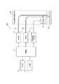
図9に示すように、第2の実施形態では、光走査型観察装置100は、光源部11、光走査型内視鏡本体120、検出部13、駆動電流生成部14、制御部15、表示部16、および入力部17を含んで構成される(図9参照)。光源部11、検出部13、駆動電流生成部14、表示部16、および入力部17の構成および機能は、第1の実施形態と同様である。
As shown in FIG. 9, in the second embodiment, the optical
光走査型内視鏡本体120には、第1の実施形態と異なり、温度センサが必ずしも設けられない。光走査型内視鏡本体120に温度センサが必ずしも設けられない点以外の光走査型内視鏡本体120の構成および機能は、第1の実施形態と同様である。
Unlike the first embodiment, the optical scanning endoscope
制御部15は、第1の実施形態と同様に、光源部11、検出部13、および駆動電流生成部14を制御することにより、画像を合成し表示部16に表示する。また、制御部15は、第1の実施形態と同様に、光走査型観察装置100に走査速度や表示画像の明るさ等、種々の設定を行うことができる。制御部15は、第1の実施形態と異なり、使用者による周波数変更の入力を入力部17が検出するときに、入力に基づいて駆動信号の周波数を決定する。
As in the first embodiment, the
以上のような構成の第2の実施形態の光走査型観察装置によっても、駆動信号の周波数を変更可能なので、画角の狭小化を抑制可能である。また、第2の実施形態の光走査型観察装置によっても、照明用光ファイバ19および検出用光ファイババンドル20は高い耐熱性および耐放射線性を有するので、高温環境下および/または高放射線下において照明用光ファイバ19および検出用光ファイババンドル20の劣化および形状変化を抑制可能である。
Even with the optical scanning observation apparatus according to the second embodiment having the above-described configuration, the frequency of the drive signal can be changed, so that the narrowing of the angle of view can be suppressed. Further, also in the optical scanning observation apparatus of the second embodiment, the illumination
本発明を諸図面や実施形態に基づき説明してきたが、当業者であれば本開示に基づき種々の変形や修正を行うことが容易であることに注意されたい。従って、これらの変形や修正は本発明の範囲に含まれることに留意されたい。 Although the present invention has been described based on the drawings and embodiments, it should be noted that those skilled in the art can easily make various changes and modifications based on the present disclosure. Therefore, it should be noted that these variations and modifications are included in the scope of the present invention.
例えば、第1の実施形態および第2の実施形態において、走査部21は、偏向磁場発生用コイル30a〜30dおよび永久磁石31を用いて、揺動部19bを振動させる構成であるが、例えば圧電素子などの他の駆動手段を用いてもよい。ただし、高温環境下において使用することが想定される場合には、第1の実施形態および第2の実施形態における偏向磁場発生用コイル30a〜30dおよび永久磁石31の組合せのように、対温度特性の優れた駆動手段を用いることが好ましい。また、本発明の光走査型観察装置は、光走査型内視鏡装置のみならず、顕微鏡などの他の装置にも適用可能である。
For example, in the first and second embodiments, the
10、100 光走査型観察装置
11 光源部
12、120 光走査型内視鏡本体
13 検出部
14 駆動電流生成部
15 制御部
16 表示部
17 入力部
18 記憶部
19 照明用光ファイバ
19a 固定端
19b 揺動部
19c 先端部
20 検出用光ファイババンドル
21 走査部
22 配線ケーブル
23 温度センサ
24 配線ケーブル
25 操作部
26 挿入部
27 先端部
28a、28b 投影用レンズ
29 角型チューブ
30a〜30d 偏向磁場発生用コイル
31 永久磁石
32 取付環
33 コア
34 クラッド
35 被覆
36 光ファイバ保護ジャケット
obj 被観察物
DESCRIPTION OF
Claims (5)
前記揺動部を、駆動信号に基づいて振動させる振動駆動手段と、
前記振動駆動手段に送信する前記駆動信号の周波数を変更する変更手段とを備える
ことを特徴とする光走査型観察装置。 An optical fiber having a swinging portion whose one end is swingably supported;
Vibration drive means for vibrating the rocking portion based on a drive signal;
An optical scanning observation apparatus comprising: changing means for changing a frequency of the drive signal transmitted to the vibration drive means.
前記揺動部近傍の温度を検出する温度センサを、さらに備え、
前記変更手段は、前記温度センサが検出した温度に基づいて、前記駆動信号の周波数を変更する
ことを特徴とする光走査型観察装置。 The optical scanning observation apparatus according to claim 1,
A temperature sensor for detecting the temperature in the vicinity of the swinging portion,
The changing means changes the frequency of the drive signal based on the temperature detected by the temperature sensor. An optical scanning observation apparatus.
前記揺動部近傍の温度に対する周波数の対応を記憶する記憶手段を、さらに備え、
前記変更手段は、前記温度センサが検出した温度に対応する周波数を前記記憶手段から読出し、該周波数に前記駆動信号の周波数を合わせる
ことを特徴とする光走査型観察装置。 The optical scanning observation apparatus according to claim 2,
Storage means for storing the correspondence of the frequency to the temperature in the vicinity of the oscillating portion;
The optical scanning observation apparatus, wherein the changing unit reads a frequency corresponding to the temperature detected by the temperature sensor from the storage unit, and matches the frequency of the drive signal with the frequency.
純粋石英、フッ素添加石英、および水酸基添加石英の少なくとも一つを含むコアと、純粋石英、フッ素添加石英、および水酸基添加石英の少なくとも一つを含むクラッドと、ポリイミド樹脂、ポリエチルエーテルケトン樹脂、およびアクリレート樹脂の少なくとも一つを含む被覆と、ポリイミド樹脂、ポリエチルエーテルケトン樹脂、およびアクリレート樹脂の少なくとも一つを含む保護ジャケットとを有し、
前記揺動部から出射する光と被観察物との相互作用による光を伝播する検出用光ファイバを、さらに備える
ことを特徴とする光走査型観察装置。 The optical scanning observation apparatus according to any one of claims 1 to 4,
A core including at least one of pure quartz, fluorine-added quartz, and hydroxyl-added quartz; a clad including at least one of pure quartz, fluorine-added quartz, and hydroxyl-added quartz; polyimide resin, polyethyl ether ketone resin, and acrylate A coating including at least one of a resin and a protective jacket including at least one of a polyimide resin, a polyethyl ether ketone resin, and an acrylate resin;
An optical scanning observation apparatus, further comprising: a detection optical fiber that propagates light generated by the interaction between the light emitted from the swinging unit and the object to be observed.
Priority Applications (5)
| Application Number | Priority Date | Filing Date | Title |
|---|---|---|---|
| JP2013014819A JP2014145942A (en) | 2013-01-29 | 2013-01-29 | Optical scanning observation device |
| EP14746497.8A EP2952947A4 (en) | 2013-01-29 | 2014-01-28 | Optical scanning observation device |
| PCT/JP2014/000428 WO2014119288A1 (en) | 2013-01-29 | 2014-01-28 | Optical scanning observation device |
| CN201480006243.4A CN104981724A (en) | 2013-01-29 | 2014-01-28 | Optical scanning observation device |
| US14/812,567 US20150338646A1 (en) | 2013-01-29 | 2015-07-29 | Optical scanning observation apparatus |
Applications Claiming Priority (1)
| Application Number | Priority Date | Filing Date | Title |
|---|---|---|---|
| JP2013014819A JP2014145942A (en) | 2013-01-29 | 2013-01-29 | Optical scanning observation device |
Publications (1)
| Publication Number | Publication Date |
|---|---|
| JP2014145942A true JP2014145942A (en) | 2014-08-14 |
Family
ID=51262006
Family Applications (1)
| Application Number | Title | Priority Date | Filing Date |
|---|---|---|---|
| JP2013014819A Pending JP2014145942A (en) | 2013-01-29 | 2013-01-29 | Optical scanning observation device |
Country Status (5)
| Country | Link |
|---|---|
| US (1) | US20150338646A1 (en) |
| EP (1) | EP2952947A4 (en) |
| JP (1) | JP2014145942A (en) |
| CN (1) | CN104981724A (en) |
| WO (1) | WO2014119288A1 (en) |
Cited By (10)
| Publication number | Priority date | Publication date | Assignee | Title |
|---|---|---|---|---|
| CN105167734A (en) * | 2015-09-29 | 2015-12-23 | 上海交通大学 | Double-magnet single-optical-fiber endoscope scanning probe and preparation method thereof |
| WO2016031289A1 (en) * | 2014-08-26 | 2016-03-03 | オリンパス株式会社 | Scanning endoscope apparatus |
| WO2016075994A1 (en) * | 2014-11-10 | 2016-05-19 | オリンパス株式会社 | Optical scanning observation system |
| WO2016143160A1 (en) * | 2015-03-12 | 2016-09-15 | オリンパス株式会社 | Scanning endoscope system |
| WO2016189591A1 (en) * | 2015-05-22 | 2016-12-01 | オリンパス株式会社 | Scanning endoscope and control method therefor |
| WO2016208222A1 (en) * | 2015-06-22 | 2016-12-29 | オリンパス株式会社 | Scanning endoscope |
| WO2017006599A1 (en) * | 2015-07-07 | 2017-01-12 | オリンパス株式会社 | Scanning endoscope system |
| JP2017077285A (en) * | 2015-10-19 | 2017-04-27 | オリンパス株式会社 | Optical scanning observation system |
| US10034599B2 (en) | 2015-01-20 | 2018-07-31 | Olympus Corporation | Scanning endoscope apparatus with scanning endoscope and determination circuit for determining whether scanning endoscope is abnormal |
| CN110471175A (en) * | 2018-05-09 | 2019-11-19 | 富士胶片株式会社 | Endoscope |
Families Citing this family (5)
| Publication number | Priority date | Publication date | Assignee | Title |
|---|---|---|---|---|
| JP6280806B2 (en) * | 2014-05-02 | 2018-02-14 | オリンパス株式会社 | Optical fiber scanning device and optical scanning endoscope |
| JP6445809B2 (en) * | 2014-09-01 | 2018-12-26 | オリンパス株式会社 | Optical scanning observation device |
| JPWO2017163361A1 (en) * | 2016-03-24 | 2019-01-31 | オリンパス株式会社 | Optical scanning device |
| US11105973B2 (en) | 2019-01-11 | 2021-08-31 | Schott Corporation | Optically enhanced high resolution image guides |
| CN117017176A (en) * | 2023-10-08 | 2023-11-10 | 峰郅科技(上海)有限公司 | Optical fiber detection imaging device and imaging method thereof |
Citations (6)
| Publication number | Priority date | Publication date | Assignee | Title |
|---|---|---|---|---|
| JPS6214604A (en) * | 1985-07-12 | 1987-01-23 | Furukawa Electric Co Ltd:The | Radiation-resisting fiber scope |
| JPH04158313A (en) * | 1990-10-23 | 1992-06-01 | Fujikura Ltd | Oscillation type fiber scope |
| JP2003307634A (en) * | 2002-04-17 | 2003-10-31 | Mitsubishi Cable Ind Ltd | Bundle light guide |
| JP2008514344A (en) * | 2004-10-01 | 2008-05-08 | ユニバーシティ・オブ・ワシントン | Configuration memory for scanning beam devices |
| JP2010162090A (en) * | 2009-01-13 | 2010-07-29 | Hoya Corp | Optical scanning endoscope |
| JP2011004920A (en) * | 2009-06-25 | 2011-01-13 | Hoya Corp | Endoscope apparatus |
Family Cites Families (3)
| Publication number | Priority date | Publication date | Assignee | Title |
|---|---|---|---|---|
| EP2048529B1 (en) * | 2006-07-28 | 2018-10-24 | The Furukawa Electric Co., Ltd. | Optical fiber |
| US8305432B2 (en) * | 2007-01-10 | 2012-11-06 | University Of Washington | Scanning beam device calibration |
| CN102483499A (en) * | 2010-08-18 | 2012-05-30 | 株式会社藤仓 | Polarization maintaining fiber and optical fiber sensor using same |
-
2013
- 2013-01-29 JP JP2013014819A patent/JP2014145942A/en active Pending
-
2014
- 2014-01-28 CN CN201480006243.4A patent/CN104981724A/en active Pending
- 2014-01-28 WO PCT/JP2014/000428 patent/WO2014119288A1/en active Application Filing
- 2014-01-28 EP EP14746497.8A patent/EP2952947A4/en not_active Withdrawn
-
2015
- 2015-07-29 US US14/812,567 patent/US20150338646A1/en not_active Abandoned
Patent Citations (6)
| Publication number | Priority date | Publication date | Assignee | Title |
|---|---|---|---|---|
| JPS6214604A (en) * | 1985-07-12 | 1987-01-23 | Furukawa Electric Co Ltd:The | Radiation-resisting fiber scope |
| JPH04158313A (en) * | 1990-10-23 | 1992-06-01 | Fujikura Ltd | Oscillation type fiber scope |
| JP2003307634A (en) * | 2002-04-17 | 2003-10-31 | Mitsubishi Cable Ind Ltd | Bundle light guide |
| JP2008514344A (en) * | 2004-10-01 | 2008-05-08 | ユニバーシティ・オブ・ワシントン | Configuration memory for scanning beam devices |
| JP2010162090A (en) * | 2009-01-13 | 2010-07-29 | Hoya Corp | Optical scanning endoscope |
| JP2011004920A (en) * | 2009-06-25 | 2011-01-13 | Hoya Corp | Endoscope apparatus |
Cited By (21)
| Publication number | Priority date | Publication date | Assignee | Title |
|---|---|---|---|---|
| CN106659361A (en) * | 2014-08-26 | 2017-05-10 | 奥林巴斯株式会社 | Scanning Endoscope Apparatus |
| WO2016031289A1 (en) * | 2014-08-26 | 2016-03-03 | オリンパス株式会社 | Scanning endoscope apparatus |
| US9974432B2 (en) | 2014-08-26 | 2018-05-22 | Olympus Corporation | Scanning endoscope apparatus with drive signal correction |
| WO2016075994A1 (en) * | 2014-11-10 | 2016-05-19 | オリンパス株式会社 | Optical scanning observation system |
| JP5974208B1 (en) * | 2014-11-10 | 2016-08-23 | オリンパス株式会社 | Optical scanning observation system |
| US9962065B2 (en) | 2014-11-10 | 2018-05-08 | Olympus Corporation | Optical scanning observation system with drive voltage correction |
| US10034599B2 (en) | 2015-01-20 | 2018-07-31 | Olympus Corporation | Scanning endoscope apparatus with scanning endoscope and determination circuit for determining whether scanning endoscope is abnormal |
| JPWO2016143160A1 (en) * | 2015-03-12 | 2017-04-27 | オリンパス株式会社 | Scanning endoscope system |
| WO2016143160A1 (en) * | 2015-03-12 | 2016-09-15 | オリンパス株式会社 | Scanning endoscope system |
| CN107405044A (en) * | 2015-03-12 | 2017-11-28 | 奥林巴斯株式会社 | Sweep type endoscopic system |
| US10758112B2 (en) | 2015-05-22 | 2020-09-01 | Olympus Corporation | Scanning endoscope and method for controlling the same |
| JPWO2016189591A1 (en) * | 2015-05-22 | 2018-03-08 | オリンパス株式会社 | Scanning endoscope and control method thereof |
| WO2016189591A1 (en) * | 2015-05-22 | 2016-12-01 | オリンパス株式会社 | Scanning endoscope and control method therefor |
| WO2016208222A1 (en) * | 2015-06-22 | 2016-12-29 | オリンパス株式会社 | Scanning endoscope |
| JP6072397B1 (en) * | 2015-06-22 | 2017-02-01 | オリンパス株式会社 | Scanning endoscope device |
| WO2017006599A1 (en) * | 2015-07-07 | 2017-01-12 | オリンパス株式会社 | Scanning endoscope system |
| JPWO2017006599A1 (en) * | 2015-07-07 | 2018-04-19 | オリンパス株式会社 | Scanning endoscope system |
| US10765296B2 (en) | 2015-07-07 | 2020-09-08 | Olympus Corporation | Scanning endoscope system |
| CN105167734A (en) * | 2015-09-29 | 2015-12-23 | 上海交通大学 | Double-magnet single-optical-fiber endoscope scanning probe and preparation method thereof |
| JP2017077285A (en) * | 2015-10-19 | 2017-04-27 | オリンパス株式会社 | Optical scanning observation system |
| CN110471175A (en) * | 2018-05-09 | 2019-11-19 | 富士胶片株式会社 | Endoscope |
Also Published As
| Publication number | Publication date |
|---|---|
| CN104981724A (en) | 2015-10-14 |
| EP2952947A4 (en) | 2016-09-28 |
| WO2014119288A1 (en) | 2014-08-07 |
| US20150338646A1 (en) | 2015-11-26 |
| EP2952947A1 (en) | 2015-12-09 |
Similar Documents
| Publication | Publication Date | Title |
|---|---|---|
| WO2014119288A1 (en) | Optical scanning observation device | |
| JP6086674B2 (en) | Optical scanning device | |
| JP6907218B2 (en) | Polarization maintenance optical fiber in virtual / augmented reality systems | |
| JP6057743B2 (en) | Optical scanning device | |
| CN107615132B (en) | Optical scanning device, imaging device, and TOF-type analysis device | |
| WO2015004961A1 (en) | Scanning endoscope | |
| JP6226730B2 (en) | Optical scanning device and optical scanning observation device | |
| CN107407802B (en) | Method and device for setting drive condition of optical scanning device | |
| JP2010036189A (en) | Laser beam machining apparatus | |
| WO2015182137A1 (en) | Optical scanning-type endoscope device | |
| WO2016075738A1 (en) | Optical fiber scanner, illumination sysytem, and observation device | |
| JP6420359B2 (en) | Endoscope device | |
| WO2014057774A1 (en) | Endoscope device | |
| JP6518687B2 (en) | Optical scanning actuator and optical scanning device | |
| JP2011090030A (en) | Image display device | |
| WO2015037231A1 (en) | Optical scanning device | |
| JP2014044271A (en) | Optical scanning observation apparatus | |
| JP6143953B2 (en) | Scanning endoscope system | |
| CN106572787B (en) | Optical scanning-type observes device | |
| Isikman et al. | FR4 laser scanner with dynamic focus | |
| WO2016084439A1 (en) | Scanning endoscope | |
| JP6072397B1 (en) | Scanning endoscope device | |
| JP6006127B2 (en) | Optical scanning device | |
| KR102191673B1 (en) | Endomicroscopic having ultra compact lensed fiber probe | |
| WO2018235277A1 (en) | Optical fiber scanning device and endoscope |
Legal Events
| Date | Code | Title | Description |
|---|---|---|---|
| A621 | Written request for application examination |
Free format text: JAPANESE INTERMEDIATE CODE: A621 Effective date: 20150916 |
|
| A131 | Notification of reasons for refusal |
Free format text: JAPANESE INTERMEDIATE CODE: A131 Effective date: 20160510 |
|
| A521 | Request for written amendment filed |
Free format text: JAPANESE INTERMEDIATE CODE: A523 Effective date: 20160706 |
|
| A131 | Notification of reasons for refusal |
Free format text: JAPANESE INTERMEDIATE CODE: A131 Effective date: 20160816 |
|
| A02 | Decision of refusal |
Free format text: JAPANESE INTERMEDIATE CODE: A02 Effective date: 20170228 |