JP2014142009A - Manufacturing method of link member for vibration-proof device and link member for vibration-proof device - Google Patents
Manufacturing method of link member for vibration-proof device and link member for vibration-proof device Download PDFInfo
- Publication number
- JP2014142009A JP2014142009A JP2013010457A JP2013010457A JP2014142009A JP 2014142009 A JP2014142009 A JP 2014142009A JP 2013010457 A JP2013010457 A JP 2013010457A JP 2013010457 A JP2013010457 A JP 2013010457A JP 2014142009 A JP2014142009 A JP 2014142009A
- Authority
- JP
- Japan
- Prior art keywords
- vibration
- leg
- link member
- portions
- cylindrical
- Prior art date
- Legal status (The legal status is an assumption and is not a legal conclusion. Google has not performed a legal analysis and makes no representation as to the accuracy of the status listed.)
- Granted
Links
Images


Abstract
Description
本発明は、内部に第1防振部材が配設される筒状部と、該筒状部から一側にそれぞれ延び且つ互いに間隔を空けて対向してその間に第2防振部材が配設される一対の脚部とを備えている防振装置用リンク部材の製造方法及びこの製造方法により製造された防振装置用リンク部材に関するものである。 The present invention includes a cylindrical portion in which a first vibration isolating member is disposed, and a second vibration isolating member that extends from the cylindrical portion to one side and is opposed to each other with a space therebetween. The present invention relates to a method of manufacturing a vibration isolator link member including a pair of leg portions and a vibration isolator link member manufactured by the manufacturing method.
筒状部と該筒状部から一側にそれぞれ延び且つ互いに間隔を空けて対向する一対の脚部とを有するリンク部材と、筒状部内に配設された第1防振部材と、両脚部の間に配設された第2防振部材とを備えている防振装置が従来技術として知られている。 A link member having a tubular portion and a pair of legs that extend from the tubular portion to one side and face each other with a space therebetween, a first vibration isolation member disposed in the tubular portion, and both leg portions An anti-vibration device including a second anti-vibration member disposed between the two is known as a prior art.
例えば、特許文献1に示すものは、第1防振機構と第2防振機構とから成り、第1防振機構は、第1円筒部(筒状部)と第1連結ブラケット(脚部)と第1防振ブッシュ(第1防振部材)とを備え、第2防振機構は、第2円筒部と第2連結ブラケットと第2防振ブッシュ(第2防振部材)とを備える。第1円筒部に対して第1連結ブラケットを位置決めするための第1位置決め部が第1円筒部に形成され、第2円筒部に対して第2連結ブラケットを位置決めするための第2位置決め部が第2円筒部に形成されている。これにより、製品ごとの第1円筒部及び第2円筒部の強度のばらつきを少なくできるとともに、第1円筒部及び第2円筒部にブラケットを溶接固着する際の作業者の手間を軽減して製作コストを低廉化できる。 For example, Patent Document 1 includes a first vibration isolation mechanism and a second vibration isolation mechanism. The first vibration isolation mechanism includes a first cylindrical portion (tubular portion) and a first connection bracket (leg portion). And a first vibration isolation bush (first vibration isolation member), and the second vibration isolation mechanism includes a second cylindrical portion, a second connection bracket, and a second vibration isolation bush (second vibration isolation member). A first positioning portion for positioning the first connecting bracket with respect to the first cylindrical portion is formed in the first cylindrical portion, and a second positioning portion for positioning the second connecting bracket with respect to the second cylindrical portion is provided. It is formed in the second cylindrical part. As a result, it is possible to reduce variations in the strength of the first cylindrical portion and the second cylindrical portion for each product, and reduce the labor of the operator when the bracket is welded and fixed to the first cylindrical portion and the second cylindrical portion. Cost can be reduced.
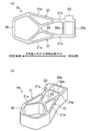
ところで、上記リンク部材を押出し成形したもの(例えばアルミ製の押出し成形品)において、該リンク部材への第2防振部材の組み付け時にその組み付け性を向上させるために、図9に示すように、両脚部a,aを厚肉にして、該各脚部aの対向面に第2防振部材bを受ける受け凹部cを切削加工することが考えられる。 By the way, in order to improve the assembling property when assembling the second vibration isolating member to the link member in the one obtained by extruding the link member (for example, an extruded product made of aluminum), as shown in FIG. It is conceivable to make both the leg portions a, a thick and to cut the receiving recesses c that receive the second vibration-proof members b on the opposing surfaces of the leg portions a.
しかしながら、図9のものでは、脚部aが厚肉であるため、リンク部材の重量や材料コストの点で好ましくない。また、受け凹部bは窪みであるため、受け凹部bを切削加工するのに、切削面積の小さい小径の刃物dしか使用できず、その加工時間や加工コストの点でも望ましくない。 However, in the thing of FIG. 9, since the leg part a is thick, it is unpreferable at the point of the weight of a link member, or material cost. Further, since the receiving recess b is a depression, only the small-diameter blade d having a small cutting area can be used for cutting the receiving recess b, which is not desirable in terms of processing time and processing cost.
本発明は、かかる点に鑑みてなされたものであり、その課題とするところは、リンク部材の重量・材料コストを低減するとともに、第2防振部材を受ける受け部の加工時間を短縮し且つその加工コストを低減することにある。 The present invention has been made in view of such a point, and the problem is that the weight and material cost of the link member are reduced, and the processing time of the receiving portion that receives the second vibration isolating member is shortened, and The processing cost is to be reduced.
上記の課題を解決するため、本発明は、両脚部の対向面の少なくとも一方にその対向方向の内側に突起する受け部を形成することを特徴とする。 In order to solve the above-mentioned problems, the present invention is characterized in that a receiving portion that protrudes inward in the facing direction is formed on at least one of the facing surfaces of both leg portions.
具体的には、本発明は、内部に第1防振部材が配設される筒状部と、該筒状部から一側にそれぞれ延び且つ互いに間隔を空けて対向してその間に第2防振部材が配設される一対の脚部とを備えている防振装置用リンク部材の製造方法を対象とし、次のような解決手段を講じた。 Specifically, the present invention includes a cylindrical portion in which a first vibration isolating member is disposed, and a second anti-vibration portion extending from the cylindrical portion to one side and facing each other with a space therebetween. The following solution was taken for the manufacturing method of the link member for vibration isolator provided with a pair of leg part by which a vibration member is arrange | positioned.
すなわち、第1の発明は、上記筒状部と、上記一対の脚部と、該両脚部の対向面の少なくとも一方に筒軸方向全域に亘って連続するように形成される連続部とを備える中間品を押出し成形し、上記連続部を加工することにより、上記両脚部の対向面の少なくとも一方にその対向方向の内側に突起し且つ上記第2防振部材を受ける受け部を形成することを特徴とするものである。 That is, the first invention includes the cylindrical portion, the pair of leg portions, and a continuous portion formed to be continuous over at least one of the opposing surfaces of the both leg portions over the entire region in the cylindrical axis direction. Extruding the intermediate product and processing the continuous portion to form a receiving portion that protrudes inward in the facing direction and receives the second vibration isolating member on at least one of the facing surfaces of the both leg portions. It is a feature.
これによれば、受け部は、両脚部の対向面の少なくとも一方からその対向方向の内側に突起した突起であるため、脚部を薄肉にできるとともに、両脚部の対向面の少なくとも一方に形成された連続部を加工することにより、そのような受け部を形成するのに、大径の刃物を使用できる。このため、リンク部材の重量・材料コストを低減するとともに、受け部の加工時間を短縮し且つその加工コストを低減することができる。 According to this, since the receiving portion is a protrusion protruding inward in the opposing direction from at least one of the opposing surfaces of both leg portions, the leg portion can be made thin and formed on at least one of the opposing surfaces of both leg portions. A large-diameter blade can be used to form such a receiving portion by processing the continuous portion. For this reason, while reducing the weight and material cost of a link member, the processing time of a receiving part can be shortened and the processing cost can be reduced.
第2の発明は、上記第1の発明において、上記連続部は、上記両脚部の対向面の間に掛け渡された架設部であることを特徴とするものである。 According to a second aspect, in the first aspect, the continuous portion is a erection portion that is spanned between opposing surfaces of the both leg portions.
ところで、中間品を押出し成形した後、その冷却時に両脚部が変形して、その間の距離寸法がばらつくことがある。これは、脚部の長さが長いほど顕著である。 By the way, after extruding an intermediate product, both legs may be deformed during cooling and the distance between them may vary. This is more conspicuous as the leg length is longer.
ここに、第2の発明によれば、中間品は、両脚部の対向面の間に掛け渡された架設部を備えているため、中間品の冷却時に両脚部の間の距離寸法がばらつくことをその架設部により抑制することができる。 According to the second aspect of the present invention, since the intermediate product includes the erection portion that is spanned between the opposing surfaces of both legs, the distance between the legs varies when the intermediate product is cooled. Can be suppressed by the installation portion.
第3の発明は、上記第1又は第2の発明の製造方法により製造された防振装置用リンク部材である。 3rd invention is the link member for vibration isolator manufactured by the manufacturing method of the said 1st or 2nd invention.
本発明によれば、受け部は、両脚部の対向面の少なくとも一方からその対向方向の内側に突起した突起であるため、脚部を薄肉にできるとともに、そのような受け部を形成するのに大径の刃物を使用できることから、リンク部材の重量・材料コストを低減するとともに、受け部の加工時間を短縮し且つその加工コストを低減することができる。 According to the present invention, since the receiving part is a protrusion protruding inward in the opposing direction from at least one of the opposing surfaces of the both leg parts, the leg part can be made thin, and such a receiving part can be formed. Since a cutter with a large diameter can be used, the weight and material cost of the link member can be reduced, the processing time of the receiving portion can be shortened, and the processing cost can be reduced.
以下、本発明の実施形態を図面に基づいて詳細に説明する。以下の好ましい実施形態の説明は、本質的に例示に過ぎず、本発明、その適用物或いはその用途を制限することを意図するものではない。 Hereinafter, embodiments of the present invention will be described in detail with reference to the drawings. The following description of the preferred embodiments is merely exemplary in nature and is not intended to limit the invention, its application, or its use.
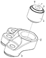
図1及び図2は、本発明の実施形態に係る防振装置1を示している。防振装置1は、図示しないパワープラントの下端部と該パワープラントの車体後方に位置する図示しない車両のサブフレームとを連結している。そして、例えば車両の急加減速時には、パワープラントが振り子のように車体前後方向に大きく揺れようとする。そうした車体前後方向の揺れは、パワープラントとサブフレームとが防振装置1を介して連結されていることにより規制されている。このように、本実施形態に係る防振装置1には、主に車両前後方向の荷重が入力される。 1 and 2 show a vibration isolator 1 according to an embodiment of the present invention. The vibration isolator 1 connects a lower end portion of a power plant (not shown) and a subframe of a vehicle (not shown) located behind the vehicle body of the power plant. For example, when the vehicle suddenly accelerates or decelerates, the power plant tends to shake greatly in the longitudinal direction of the vehicle body like a pendulum. Such shaking in the longitudinal direction of the vehicle body is regulated by the power plant and the subframe being connected via the vibration isolator 1. Thus, the load in the vehicle front-rear direction is mainly input to the vibration isolator 1 according to the present embodiment.
防振装置1は、筒状部20と一対の脚部21,21とを有するリンク金具2(リンク部材)と、該筒状部20内に配設され、該筒状部20の内周面に第1弾性部材30を介して連結される第1内筒体31と、両脚部21,21の間に配設され、パワープラントに取り付けられる第2防振部材4とを備えている。尚、第1弾性部材30及び第1内筒体31は第1防振部材を構成する。
The vibration isolator 1 includes a link fitting 2 (link member) having a
上記リンク金具2は、アルミ製の押出し成形品で構成されていて、その長手方向が車両前後方向に一致するように配設されている。
The
上記筒状部20は、リンク金具2の長手方向の一端部に形成されている。筒状部20は、筒軸方向から見て、外形が概ね六角形状をなす筒状に形成されている。筒状部20の内周面における車両前後方向両側の端面には、車両前後方向内側に突出する後述する第1及び第2ストッパ部30c,30dが形成されている。該第1及び第2ストッパ部30c,30dは、ゴム弾性体により形成されている。
The
上記一対の脚部21,21は、筒状部20における主荷重入力方向(車両前後方向)に直交する方向の両端部から主荷重入力方向の一側(車両前側)にそれぞれ延び且つ互いに間隔を空けて対向している。各脚部21は、筒状部20から主荷重入力方向の一側(車両前側)に向かうに従って、主荷重入力方向(車両前後方向)と直交する方向の内側に傾斜するように延びる傾斜部21aと、該傾斜部21aにおける主荷重入力方向の一側の端部から主荷重入力方向の一側に向かって延びる平行部21bとを有している。両脚部21,21の平行部21b,21bは、互いに平行に配設されている。この一対の平行部21b,21bが、第2防振部材4を締結固定する締結部として機能する。
The pair of
上記両平行部21b,21bの対向面(主荷重入力方向と直交する方向の内側の面)における筒軸方向の一側の端部(下端部)には、その対向方向の内側(主荷重入力方向と直交する方向の内側)に突起し且つ第2防振部材4の第2内筒体40を受ける受け部(誘い込み部)22が一体形成されている。該受け部22は、各平行部21bに主荷重入力方向に互いに間隔を空けて配置された第1及び第2受け部22a,22bで構成されている。両平行部21b,21bの第1受け部22a,22aは、互いに主荷重入力方向と直交する方向に対向配置されている。両平行部21b,21bの第2受け部22b,22bも、互いに主荷重入力方向と直交する方向に対向配置されている。各受け部22a,22bの第2内筒体40側の面(上端面)は、該第2内筒体40の形状に合うように円弧面状に形成されている。各受け部22a,22bは、後述する架設部(ブリッジ部)26を加工することにより成形されている。この4つの受け部22a,22bが、リンク金具2への第2防振部材4の組み付け時に該第2防振部材4の第2内筒体40を受けて所定位置に保持し、その組み付け性を向上させる機能を有している。
An end portion (lower end portion) on one side of the cylinder axis direction on the opposing surface (the inner surface in the direction orthogonal to the main load input direction) of the
一方の平行部21bにおける主荷重入力方向(車両前後方向)と直交する方向の外側の面にはボス部23が形成されている。該ボス部23にはボルト孔24が形成されている。他方の平行部21bにもボルト孔24が形成されている。両平行部21b,21bのボルト孔24,24は、互いに主荷重入力方向と直交する方向に対向配置されている。両ボルト孔24,24には、第2防振部材4の第2内筒体40の筒孔に挿通されたボルト5が螺合されている。
A
筒状部20における主荷重入力方向の一側(車両前側)の端部と、各脚部21における傾斜部21aと平行部21bとの接続部との間にはそれぞれ、補強部25が連結されている。各補強部25は、筒状部20から主荷重入力方向の一側(車両前側)に向かうに従って、主荷重入力方向(車両前後方向)と直交する方向の外側に傾斜するように延びている。
Reinforcing
上記第1内筒体31は、外形が概ね六角形状をなす筒状の金属部材からなる。第1内筒体31は、筒状部20内における主荷重入力方向の中央位置よりも脚部21側(車両前側)にややオフセットした位置に配設されている。第1内筒体31は、上述の如く第1弾性部材30を介して筒状部20の内周面に弾性連結されている。第1内筒体31は、その筒孔に挿通された不図示のボルトによりサブフレームに連結され、これにより、防振装置1の筒状部20側がサブフレームに連結される。
The first
上記第1弾性部材30は、ゴム弾性体で構成されている。第1弾性部材30は、第1内筒体31から径方向外側に延びる一対の弾性腕部30a,30aと、筒状部20の内周面を全周に亘って薄皮状に覆う枠状部30bとを有している。該枠状部30bには、ゴム製の第1ストッパ部30cと、第1内筒体31を挟んで第1ストッパ部30cの反対側に位置するゴム製の第2ストッパ部30dとが一体形成されている。
The first
上記一対の弾性腕部30a,30aは、防振装置1の平面視において、略V字状をなすように配置されている。より詳細には、各弾性腕部30aは、第1内筒体31の外周面から径方向外側に向かって、主荷重入力方向(車両前後方向)に直交する方向に対して該主荷重入力方向の他側(車両後側)に傾斜するように延びて筒状部20の内周面に接続されている。この一対の弾性腕部30a,30aが、防振装置1に入力された振動を吸収する主バネ部として機能する。
The pair of
上記第1弾性部材30は、加硫成形により第1内筒体31及び筒状部20に一体成形されている。具体的には、不図示の射出成形金型に対して、リンク金具2を設置した後、該リンク金具2の筒状部20の内側に第1内筒体31をセットし、型締め後に、射出成形金型のキャビティに未加硫のゴム弾性体を射出して加熱加硫することで、リンク金具2及び第1弾性部材30が加硫接着により一体化されている。これにより、第1内筒体31、第1弾性部材30、及び筒状部20が加硫接着により一体化されている。このように加硫一体成形を採用することで、例えば、ブッシュタイプの加硫成形品を筒状部20に圧入する場合に比べて、筒状部20の形状自由度を高めることができる。したがって、筒状部20の形状を、円筒状に限らず、本実施形態の如く、比較的複雑な形状にすることができる。さらに、ブッシュ圧入方式を採用した場合に必要となる外筒体を省略して製造コストを低減することができる。
The first
上記第2防振部材4は、ブッシュタイプの加硫成形品である。つまり、第2防振部材4は、図3及び図4に示すように、第2内筒体40と、該第2内筒体40の外周面に第2弾性部材42を介して連結される第2外筒体42とを有している。
The second
上記第2内筒体40は、円筒状の金属部材からなる。第2内筒体40は、その軸心が第1内筒体31の軸心に直交するように配設されている。第2内筒体40は、第2外筒体42内に同軸に配設されていて、上述の如く第2弾性部材42を介して第2外筒体42の内周面に連結されている。該第2弾性部材42は、第2内筒体40の外周面を囲むようにその全周に亘って形成されている。この第2外筒体42内の第2弾性部材42も、上記第1弾性部材30と同様に、加硫接合により第2内筒体40及び第2外筒体42に一体成形されている。
The second
上記第2内筒体40は、その筒孔に挿通されたボルト5によりリンク金具2の両脚部21,21の平行部21b,21bの間に連結されている。
The second inner
上記第2防振部材4は、圧入孔43aに該第2防振部材4が圧入されたブラケット43によりパワープラントの下端部に連結され、これにより、防振装置1の脚部21側がパワープラントに連結される。こうして、第1内筒体31がサブフレームに連結されることと、第2防振部材4がブラケット43を介してパワープラントに連結されることとにより、サブフレームとパワープラントとが防振装置1を介して連結される。
The second
以下、防振装置1の製造方法について図5〜図8等を参照しながら説明する。 Hereinafter, the manufacturing method of the vibration isolator 1 will be described with reference to FIGS.
まず、図5に示すように、アルミニウムの延性固体あるいは半固体を、適当な形のダイス出口に強制的に通して、上記筒状部20と、上記一対の脚部21,21と、上記一対の補強部25,25と、上記ボス部23と、両脚部21,21の平行部21b,21bの対向面(主荷重入力方向と直交する方向の内側の面)の間に掛け渡され且つその筒軸方向全域に亘って連続するように形成される架設部26(連続部)とを備える、リンク金具2の連続的な中間品2aを押出し成形する。
First, as shown in FIG. 5, a ductile solid or semi-solid of aluminum is forcibly passed through a die outlet having an appropriate shape, and the
上記架設部26は、両平行部21b,21bの間に主荷重入力方向に互いに間隔を空けて配置された第1及び第2架設部26a,26bで構成されている。該第1架設部26aは、上記第1受け部22aに対応する位置に配設されている。第2架設部26bは、上記第2受け部22bに対応する位置に配設されている。この2つの架設部26a,26bが、中間品2aの冷却時に両脚部21,21の間の距離寸法がばらつくことを抑制する機能を有している。
The erection part 26 includes first and
そして、中間品2aを冷却して、その寸法を安定させた後、図6に示すように、上記両架設部26a,26bの主荷重入力方向に直交する方向の両端近傍をそれぞれ、大径の円状回転式刃物(例えば丸鋸)6により切断加工することにより、両脚部21,21の平行部21b,21bの対向面(主荷重入力方向と直交する方向の内側の面)に、その対向方向の内側(主荷重入力方向と直交する方向の内側)に突起し且つその筒軸方向全域に亘って連続する突条部27を形成する。
Then, after cooling the
上記突条部27は、各平行部21bに主荷重入力方向に互いに間隔を空けて配置された第1及び第2突条部27a,27bで構成されている。該第1突条部27aは、上記第1受け部22aに対応する位置に配設されている。第2突条部27bは、上記第2受け部22bに対応する位置に配設されている。
The ridge 27 is composed of first and
上記切断加工では、一方の脚部21側に1回、刃物6を通すことにより、該一方の脚部21の第1及び第2突条部27a,27bを一度に形成するとともに、他方の脚部21側に1回、刃物6を通すことにより、該他方の脚部21の第1及び第2突条部27a,27bを一度に形成する。
In the above cutting process, the first and
また、一方の脚部21の平行部21bのボス部23と他方の脚部21の平行部21bとに所定工具により上記ボルト孔24を形成する。
The bolt holes 24 are formed by a predetermined tool in the
次に、図7に示すように、上記両平行部21b,21bの第1及び第2突条部27a,27bをそれぞれ、大径の円状回転式刃物(例えば、第2内筒体40の外径と同じくらいの径のフライス)7により切削加工することにより、両平行部21b,21bの対向面(主荷重入力方向と直交する方向の内側の面)に、その対向方向の内側(主荷重入力方向と直交する方向の内側)に突起し且つ第2防振部材4の第2内筒体40を受ける上記第1及び第2受け部22a,22bを形成する。
Next, as shown in FIG. 7, the first and
上記切削加工では、一方の脚部21側に1回、刃物7を降ろすことにより、該一方の脚部21の第1及び第2受け部22a,22bを一度に形成するとともに、他方の脚部21側に1回、刃物7を降ろすことにより、該他方の脚部21の第1及び第2受け部22a,22bを一度に形成する。以上により、リンク金具2の製造が完了する。
In the above-described cutting process, the first and
次に、図8に示すように、上記第1弾性部材30を、加硫成形により第1内筒体31及びリンク金具2の筒状部20に一体成形する。次に、ブラケット43の圧入孔43aに圧入された第2防振部材4の第2内筒体40をリンク金具2の第1及び第2受け部22a,22bの第2内筒体40側の面(上端面)により面接触で受ける。これにより、第2防振部材4が所定位置に保持される。そして、図1及び図2に示すように、第2内筒体40を、その筒孔に挿通されたボルト5によりリンク金具2の両脚部21,21の平行部21b,21bの間に連結する。上述の如く、第2防振部材4を所定位置に保持したため、該第2防振部材4のリンク金具2への組み付け性が向上する。以上により、防振装置1の製造が完了する。
Next, as shown in FIG. 8, the first
−効果−
以上より、本実施形態によれば、受け部22は、両脚部21,21の対向面からその対向方向の内側に突起した突起であるため、脚部21を薄肉にできるとともに、両脚部21,21の対向面の間に形成された架設部26を加工することにより、そのような受け部22を形成するのに、大径の刃物6,7を使用できる。このため、リンク金具2の重量・材料コストを低減するとともに、受け部22の加工時間を短縮し且つその加工コストを低減することができる。
-Effect-
As described above, according to the present embodiment, the receiving portion 22 is a protrusion protruding inward in the opposing direction from the opposing surface of the both
また、中間品2aは、両脚部21,21の対向面の間に掛け渡された架設部26を備えているため、中間品2aの冷却時に両脚部21,21の間の距離寸法がばらつくことをその架設部26により抑制することができる。
Further, since the
(その他の実施形態)
上記実施形態では、リンク部材をアルミ製の押出し成形品としたが、これに限らず、例えば、樹脂製の押出し成形品としても良い。
(Other embodiments)
In the above embodiment, the link member is an aluminum extrusion-molded product. However, the present invention is not limited to this, and for example, a resin extrusion-molded product may be used.
また、上記実施形態では、受け部22を各脚部21に形成したが、両脚部21,21の一方に形成しても良い。
Moreover, in the said embodiment, although the receiving part 22 was formed in each
また、上記実施形態では、受け部22を各脚部21の対向面に2つずつ形成したが、1つ又は3つ以上形成しても良い。
Moreover, in the said embodiment, although the receiving part 22 was formed 2 each on the opposing surface of each
また、上記実施形態では、第2内筒体40を受け部22により面接触で受けたが、これに限らず、例えば、線接触で受けても良い。
Moreover, in the said embodiment, although the 2nd
また、上記実施形態では、架設部を2つ形成したが、1つ又は3つ以上形成しても良い。 Moreover, in the said embodiment, although two construction parts were formed, you may form one or three or more.
また、上記実施形態では、連続部として架設部26を形成したが、これに限らず、例えば、脚部21,21の対向方向の内側に突起する突条部やブロックを形成しても良い。
Moreover, in the said embodiment, although the installation part 26 was formed as a continuous part, it is not restricted to this, For example, you may form the protrusion part and block which protrude inside the opposing direction of the
また、上記実施形態では、リンク金具2の筒状部20に対して、ゴム弾性体の加硫一体成形に限らず、例えば、ブッシュタイプの加硫成形品を圧入する方式を採用するようにしてもよい。
Moreover, in the said embodiment, it is not limited to vulcanization integral molding of a rubber elastic body with respect to the
以上説明したように、本発明に係る防振装置用リンク部材の製造方法及び防振装置用リンク部材は、リンク部材の重量・材料コストを低減するとともに、第2防振部材を受ける受け部の加工時間を短縮し且つその加工コストを低減することが必要な用途等に適用することができる。 As described above, the vibration isolator link member manufacturing method and the anti-vibration device link member according to the present invention reduce the weight and material cost of the link member, and the receiving portion that receives the second anti-vibration member. The present invention can be applied to applications that need to shorten the processing time and reduce the processing cost.
1 防振装置
2 リンク金具(リンク部材)
2a 中間品
20 筒状部
21 脚部
22 受け部
26 架設部(連続部)
30 第1弾性部材 (第1防振部材)
31 第1内筒体(第1防振部材)
4 第2防振部材
1 Vibration isolator
2 Link bracket (link member)
2a Intermediate product
20 cylindrical part
21 legs
22 Receiver
26 Construction part (continuous part)
30 1st elastic member (1st anti-vibration member)
31 1st inner cylinder (1st vibration isolator)
4 Second vibration isolation member
Claims (3)
上記筒状部と、上記一対の脚部と、該両脚部の対向面の少なくとも一方に筒軸方向全域に亘って連続するように形成される連続部とを備える中間品を押出し成形し、
上記連続部を加工することにより、上記両脚部の対向面の少なくとも一方にその対向方向の内側に突起し且つ上記第2防振部材を受ける受け部を形成することを特徴とする防振装置用リンク部材の製造方法。 A pair of tubular portions in which the first vibration isolation member is disposed, and a second vibration isolation member disposed between the tubular portions that extend from the tubular portion to one side and are spaced apart from each other. A method of manufacturing a vibration isolator link member comprising a leg portion,
Extruding an intermediate product comprising the cylindrical portion, the pair of leg portions, and a continuous portion formed so as to be continuous over the entire region in the cylindrical axis direction on at least one of the opposing surfaces of the both leg portions,
By processing the continuous portion, a receiving portion that protrudes inward in the opposing direction and receives the second vibration isolating member is formed on at least one of the opposing surfaces of the both leg portions. A manufacturing method of a link member.
上記連続部は、上記両脚部の対向面の間に掛け渡された架設部であることを特徴とする防振装置用リンク部材の製造方法。 In the manufacturing method of the link member according to claim 1,
The method of manufacturing a vibration isolator link member, wherein the continuous portion is a erection portion that is spanned between opposing surfaces of the both leg portions.
Priority Applications (1)
| Application Number | Priority Date | Filing Date | Title |
|---|---|---|---|
| JP2013010457A JP6047020B2 (en) | 2013-01-23 | 2013-01-23 | Method for manufacturing link member for vibration isolator |
Applications Claiming Priority (1)
| Application Number | Priority Date | Filing Date | Title |
|---|---|---|---|
| JP2013010457A JP6047020B2 (en) | 2013-01-23 | 2013-01-23 | Method for manufacturing link member for vibration isolator |
Publications (2)
| Publication Number | Publication Date |
|---|---|
| JP2014142009A true JP2014142009A (en) | 2014-08-07 |
| JP6047020B2 JP6047020B2 (en) | 2016-12-21 |
Family
ID=51423465
Family Applications (1)
| Application Number | Title | Priority Date | Filing Date |
|---|---|---|---|
| JP2013010457A Expired - Fee Related JP6047020B2 (en) | 2013-01-23 | 2013-01-23 | Method for manufacturing link member for vibration isolator |
Country Status (1)
| Country | Link |
|---|---|
| JP (1) | JP6047020B2 (en) |
Cited By (4)
| Publication number | Priority date | Publication date | Assignee | Title |
|---|---|---|---|---|
| WO2017145621A1 (en) * | 2016-02-22 | 2017-08-31 | 倉敷化工株式会社 | Link member for vibration isolator and manufacturing method therefor |
| US20180229595A1 (en) * | 2017-02-16 | 2018-08-16 | Toyo Tire & Rubber Co., Ltd. | Torque rod, and method for manufacturing torque rod |
| JP2019090516A (en) * | 2017-11-16 | 2019-06-13 | 株式会社ブリヂストン | Bracket for vibration control device |
| JP2020112255A (en) * | 2019-01-16 | 2020-07-27 | トヨタ自動車株式会社 | Torque rod structure |
Citations (3)
| Publication number | Priority date | Publication date | Assignee | Title |
|---|---|---|---|---|
| JPH07158696A (en) * | 1993-12-07 | 1995-06-20 | Kinugawa Rubber Ind Co Ltd | Engine mount fitting stopper |
| JPH1191620A (en) * | 1997-09-26 | 1999-04-06 | Daihatsu Motor Co Ltd | Mount structure of power plant |
| JP2006112572A (en) * | 2004-10-15 | 2006-04-27 | Yamashita Rubber Co Ltd | Link and method of manufacturing the same |
-
2013
- 2013-01-23 JP JP2013010457A patent/JP6047020B2/en not_active Expired - Fee Related
Patent Citations (3)
| Publication number | Priority date | Publication date | Assignee | Title |
|---|---|---|---|---|
| JPH07158696A (en) * | 1993-12-07 | 1995-06-20 | Kinugawa Rubber Ind Co Ltd | Engine mount fitting stopper |
| JPH1191620A (en) * | 1997-09-26 | 1999-04-06 | Daihatsu Motor Co Ltd | Mount structure of power plant |
| JP2006112572A (en) * | 2004-10-15 | 2006-04-27 | Yamashita Rubber Co Ltd | Link and method of manufacturing the same |
Cited By (7)
| Publication number | Priority date | Publication date | Assignee | Title |
|---|---|---|---|---|
| WO2017145621A1 (en) * | 2016-02-22 | 2017-08-31 | 倉敷化工株式会社 | Link member for vibration isolator and manufacturing method therefor |
| US20180229595A1 (en) * | 2017-02-16 | 2018-08-16 | Toyo Tire & Rubber Co., Ltd. | Torque rod, and method for manufacturing torque rod |
| EP3364065A1 (en) * | 2017-02-16 | 2018-08-22 | Toyo Tire&Rubber Co., Ltd. | Torque rod, and method for manufacturing torque rod |
| CN108443381A (en) * | 2017-02-16 | 2018-08-24 | 东洋橡胶工业株式会社 | Torque tube and its manufacturing method |
| CN108443381B (en) * | 2017-02-16 | 2020-03-10 | 东洋橡胶工业株式会社 | Torque rod and method of manufacturing the same |
| JP2019090516A (en) * | 2017-11-16 | 2019-06-13 | 株式会社ブリヂストン | Bracket for vibration control device |
| JP2020112255A (en) * | 2019-01-16 | 2020-07-27 | トヨタ自動車株式会社 | Torque rod structure |
Also Published As
| Publication number | Publication date |
|---|---|
| JP6047020B2 (en) | 2016-12-21 |
Similar Documents
| Publication | Publication Date | Title |
|---|---|---|
| JP5687400B1 (en) | Cylindrical anti-vibration device for anti-vibration connecting rod, anti-vibration connecting rod using the same, and method for manufacturing anti-vibration connecting rod | |
| JP6047020B2 (en) | Method for manufacturing link member for vibration isolator | |
| EP3018381B1 (en) | Vibration-damping structure | |
| JP6157000B2 (en) | Vibration isolator | |
| JP2008032121A (en) | Manufacturing method for cylindrical vibration control device and mounting structural body provided with cylindrical vibration control device | |
| WO2014141929A1 (en) | Antivibration device | |
| JP6418980B2 (en) | Link bracket | |
| JP2005036845A (en) | Dynamic damper | |
| JP5615677B2 (en) | Anti-vibration connecting rod | |
| JP2009115109A (en) | Vibration isolating connecting rod | |
| WO2017145621A1 (en) | Link member for vibration isolator and manufacturing method therefor | |
| JP6393443B2 (en) | Vibration isolator bracket and vibration isolator using the same | |
| JP5562821B2 (en) | Vibration isolator | |
| JP5061129B2 (en) | Vibration isolator | |
| JP2006189096A (en) | Torque rod | |
| JP2015110992A (en) | Vibration control device | |
| KR101041628B1 (en) | Torque rod mount | |
| JP2004257541A (en) | Stabilizer bushing | |
| JP2014234833A (en) | Outer bracket for cylindrical vibration-proofing device, and cylindrical vibration-proofing device with outer bracket | |
| JP2012180872A (en) | Strut mount | |
| WO2016189925A1 (en) | Vibration-damping device | |
| JP4426601B2 (en) | Vibration isolator | |
| JP4521016B2 (en) | Vibration isolator | |
| CN212804022U (en) | A vehicle that is used for bush of vehicle and has it | |
| JP4598725B2 (en) | Anti-vibration device mounting bracket |
Legal Events
| Date | Code | Title | Description |
|---|---|---|---|
| A621 | Written request for application examination |
Free format text: JAPANESE INTERMEDIATE CODE: A621 Effective date: 20151119 |
|
| A977 | Report on retrieval |
Free format text: JAPANESE INTERMEDIATE CODE: A971007 Effective date: 20160823 |
|
| A131 | Notification of reasons for refusal |
Free format text: JAPANESE INTERMEDIATE CODE: A131 Effective date: 20160830 |
|
| A521 | Written amendment |
Free format text: JAPANESE INTERMEDIATE CODE: A523 Effective date: 20161006 |
|
| TRDD | Decision of grant or rejection written | ||
| A01 | Written decision to grant a patent or to grant a registration (utility model) |
Free format text: JAPANESE INTERMEDIATE CODE: A01 Effective date: 20161108 |
|
| A61 | First payment of annual fees (during grant procedure) |
Free format text: JAPANESE INTERMEDIATE CODE: A61 Effective date: 20161118 |
|
| R150 | Certificate of patent or registration of utility model |
Ref document number: 6047020 Country of ref document: JP Free format text: JAPANESE INTERMEDIATE CODE: R150 |
|
| LAPS | Cancellation because of no payment of annual fees |