JP2014141978A - Bearing rotation state measuring monitoring device - Google Patents
Bearing rotation state measuring monitoring device Download PDFInfo
- Publication number
- JP2014141978A JP2014141978A JP2013008914A JP2013008914A JP2014141978A JP 2014141978 A JP2014141978 A JP 2014141978A JP 2013008914 A JP2013008914 A JP 2013008914A JP 2013008914 A JP2013008914 A JP 2013008914A JP 2014141978 A JP2014141978 A JP 2014141978A
- Authority
- JP
- Japan
- Prior art keywords
- bearing
- rotation state
- monitoring device
- rolling
- inner ring
- Prior art date
- Legal status (The legal status is an assumption and is not a legal conclusion. Google has not performed a legal analysis and makes no representation as to the accuracy of the status listed.)
- Pending
Links
Images
Abstract
Description
本発明は、各種の回転機械装置(例えば、航空機のジェットエンジンや産業用のガスタービンエンジンなど)の主軸を支持する軸受において、当該軸受の回転状態(例えば、軸受の温度、歪みや振動、あるいは転動体の回転数など)を計測監視するための軸受回転状態計測監視装置(以下、監視装置という)の改良に関する。 The present invention relates to a bearing that supports the main shaft of various rotating machinery devices (e.g., aircraft jet engines and industrial gas turbine engines), and the rotational state of the bearings (e.g., bearing temperature, strain and vibration, or The present invention relates to an improvement in a bearing rotation state measuring and monitoring device (hereinafter referred to as a monitoring device) for measuring and monitoring the number of rotations of rolling elements.
従来から、かかるジェットエンジンやガスタービンエンジンなどには、その主軸を支持する軸受(例えば、玉軸受、ころ軸受あるいはすべり軸受など)の回転状態を計測監視するための監視装置が設けられている。具体的な一例としては、軸受内輪または外輪に設けた孔内にセンサを設けて、軸受の温度変化、歪みや振動有無、あるいは転動体の回転数変動などの計測が行われている。これにより、軸受の回転状態(回転異常の有無)を監視し、当該軸受に対する損傷(例えば、軌道面の微小剥離など)の発生を防止しているとともに、初期段階で確実に検知し、これらのジェットエンジンやガスタービンエンジンなどの安全性確保を図っている。 Conventionally, such jet engines, gas turbine engines, and the like have been provided with a monitoring device for measuring and monitoring the rotational state of a bearing (for example, a ball bearing, a roller bearing, or a slide bearing) that supports the main shaft. As a specific example, a sensor is provided in a hole provided in the bearing inner ring or the outer ring, and measurement of temperature change of the bearing, distortion or vibration, or fluctuation of the rotational speed of the rolling element is performed. As a result, the rotation state of the bearing (the presence or absence of abnormal rotation) is monitored, and damage to the bearing (for example, minute separation of the raceway surface, etc.) is prevented. Safety of jet engines and gas turbine engines is being secured.
このような監視装置におけるセンサとしては、例えば熱電対センサなどによって軸受の回転状態(軸受温度、歪みや振動)を計測し、その結果が電気信号(以下、計測信号という)として出力されている。そして、計測信号は所定の信号処理部に送信(伝達)され、当該信号処理部によって、単位時間当たりの軸受の温度、歪みや振動などの変化・変動量を演算処理することで、かかる軸受の温度推移、歪み量や振動量などの軸受の回転状態が計測されている。 As a sensor in such a monitoring device, for example, a rotational state of the bearing (bearing temperature, strain or vibration) is measured by a thermocouple sensor or the like, and the result is output as an electrical signal (hereinafter referred to as a measurement signal). Then, the measurement signal is transmitted (transmitted) to a predetermined signal processing unit, and the signal processing unit performs arithmetic processing on the amount of change / variation such as the temperature, strain and vibration of the bearing per unit time. The rotation state of the bearing such as temperature transition, strain amount and vibration amount is measured.
ところで、例えば、ジェットエンジンやガスタービンエンジンなどの高速回転する主軸を支持する軸受は、内外輪が同時に回転する構成、すなわち内外輪がいずれも回転輪として構成される場合がある。この場合、かかる軸受の回転状態を計測監視する際、その計測精度の向上を図るべく、センサを回転体(内外輪や主軸など)に取り付け、当該回転するセンサから出力された計測信号を信号処理部に対して伝達することが必要とされる場合がある。 By the way, for example, a bearing that supports a main shaft that rotates at high speed, such as a jet engine or a gas turbine engine, may have a configuration in which inner and outer rings rotate simultaneously, that is, both inner and outer rings may be configured as rotating wheels. In this case, when measuring and monitoring the rotation state of such a bearing, in order to improve the measurement accuracy, a sensor is attached to the rotating body (inner / outer ring, main shaft, etc.), and the measurement signal output from the rotating sensor is subjected to signal processing. It may be necessary to communicate to the part.
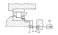
その際、回転するセンサから出力された計測信号の信号処理部に対する伝達手段としては、従来から、軸受の回転状態を計測し、計測結果を電気信号として出力する熱電対センサよりなるセンサ部12と、センサ部から出力された電気信号に基づいて発光素子16を発光させることで、電気信号を光信号に変換して出力する第1の信号変換部14と、発光素子によって発せられた光信号を受光素子18により受光し、その光信号を電気信号に変換して出力する第2の信号変換部110と、第2の信号変換部から出力された電気信号を受信して演算処理を行うと共に、回転状態を監視する制御監視部112とを備えた構成が一例として開示されている。(特許文献1)
At that time, as a means for transmitting the measurement signal output from the rotating sensor to the signal processing unit, conventionally, a
しかしながら、上記特許文献1において監視対象の軸受が鍔付き軸受にあっては、軸受のなかでも最もシビアで監視が必要な鍔面、転動面から離れた位置にセンサが配置されているため、軸受周囲の外部の熱環境などによってセンサの測定誤差が生じやすく監視判定の精度が低下するという問題が懸念されていた。また、特許文献1の測定手段として熱電対センサなどを用いると、軸受外部の熱環境の変化によって正確な軸受状態の測定が困難になるという問題も懸念されていた。
However, in the
本発明は、このような課題を解決するためになされており、その目的は、小型軽量化を図ることが可能で、且つ、高速回転する軸受の回転状態(例えば、軸受の温度、歪みや振動、転動体の回転数など)を高精度に計測監視することが可能な軸受回転状態計測監視装置を提供することにある。 The present invention has been made in order to solve such a problem, and an object of the present invention is to reduce the size and weight of the bearing and to rotate the bearing rotating at high speed (for example, the temperature, strain and vibration of the bearing). Another object of the present invention is to provide a bearing rotation state measuring and monitoring device capable of measuring and monitoring the rotational speed of rolling elements with high accuracy.
前記課題を解決するための発明は、外輪と、内輪と、前記外輪と前記内輪の間にあって相対回転させる複数の転動体とを備え、回転軸を回転可能に支持する転がり軸受の回転状態を監視するための軸受回転状態監視装置であって、前記外輪または内輪には鍔部が設けられており、前記鍔部の転動体に対向する部位に軸受軸方向に向け孔を設けるとともに、前記孔内に歪ゲージよりなる測定センサが埋め込まれていることを特徴とする。 The invention for solving the above-described problems includes an outer ring, an inner ring, and a plurality of rolling elements between the outer ring and the inner ring that rotate relative to each other, and monitors the rotation state of a rolling bearing that rotatably supports a rotating shaft. A bearing rotation state monitoring device, wherein the outer ring or the inner ring is provided with a flange, a hole facing the rolling element of the flange is provided in the bearing axial direction, A measurement sensor comprising a strain gauge is embedded in
本発明によれば、転動体と鍔部の近傍に歪センサを配置したため、軸受外部環境等に影響を受ける事無く、軸受回転状態を高精度で監視できるという効果が得られる。 According to the present invention, since the strain sensor is disposed in the vicinity of the rolling elements and the flange portion, the effect that the bearing rotation state can be monitored with high accuracy without being affected by the bearing external environment or the like can be obtained.
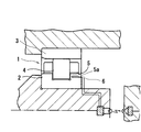
本発明を図1に基づいて説明する。転がり軸受1は、内輪2と外輪3と前記内輪2と前記外輪3との間にあって、前記内輪と前記外輪とを相対回転させる複数の円筒ころ状の転動体4を備えている。前記内輪2には転動体両端に鍔部5が設けられており、前記転動体4は前記内輪2に案内されて回転できるようになっている。
The present invention will be described with reference to FIG. The rolling
転がり軸受1は、前記鍔部5と前記転動体4間において回転よる大きな摩擦力が働き、転がり軸受1内で最も過酷な条件となるため、当該部位の回転状態を精度良く監視することで、転がり軸受1の状態を把握することが可能である。そのため、前記鍔部5内において前記転動体4と対向する位置に軸受軸方向に向け孔5aを設け、前記孔5a内に熱による影響を受けにくい歪センサよりなる測定センサ6を埋め込むことで、転動体4の状態を精度良く監視することが可能となる。なお測定センサ6から回転状態を監視する不図示の制御監視部までの回路については、特許文献1のような従来構成と同様のため説明は省略する。
Since the rolling
1…転がり軸受
2…内輪
3…外輪
4…転動体
5…鍔部
5a…孔
6…測定センサ
DESCRIPTION OF
Claims (1)
Priority Applications (1)
| Application Number | Priority Date | Filing Date | Title |
|---|---|---|---|
| JP2013008914A JP2014141978A (en) | 2013-01-22 | 2013-01-22 | Bearing rotation state measuring monitoring device |
Applications Claiming Priority (1)
| Application Number | Priority Date | Filing Date | Title |
|---|---|---|---|
| JP2013008914A JP2014141978A (en) | 2013-01-22 | 2013-01-22 | Bearing rotation state measuring monitoring device |
Publications (1)
| Publication Number | Publication Date |
|---|---|
| JP2014141978A true JP2014141978A (en) | 2014-08-07 |
Family
ID=51423440
Family Applications (1)
| Application Number | Title | Priority Date | Filing Date |
|---|---|---|---|
| JP2013008914A Pending JP2014141978A (en) | 2013-01-22 | 2013-01-22 | Bearing rotation state measuring monitoring device |
Country Status (1)
| Country | Link |
|---|---|
| JP (1) | JP2014141978A (en) |
Cited By (1)
| Publication number | Priority date | Publication date | Assignee | Title |
|---|---|---|---|---|
| CN104237039A (en) * | 2014-09-17 | 2014-12-24 | 上海大学 | Bearing ball friction-wear testing machine |
-
2013
- 2013-01-22 JP JP2013008914A patent/JP2014141978A/en active Pending
Cited By (1)
| Publication number | Priority date | Publication date | Assignee | Title |
|---|---|---|---|---|
| CN104237039A (en) * | 2014-09-17 | 2014-12-24 | 上海大学 | Bearing ball friction-wear testing machine |
Similar Documents
| Publication | Publication Date | Title |
|---|---|---|
| JP5540728B2 (en) | Roller bearing device | |
| EP2746610B1 (en) | State detection device for bearing roller, roller bearing device with sensor, and wind turbine generator | |
| US7631553B2 (en) | Bearing arrangement for mounting at least one machine elements on a support | |
| JP4993492B2 (en) | Bearing device | |
| US20160195145A1 (en) | Rotation transmission device and wind power generation device equipped with the same | |
| JPWO2017203868A1 (en) | Rolling bearing fatigue state prediction device and rolling bearing fatigue state prediction method | |
| JP2016217485A (en) | Rolling bearing including vibration detection device and state detection device | |
| WO2016133100A1 (en) | Abnormality diagnosis system | |
| WO2017150190A1 (en) | Torque measurement device, gearbox, and torque measurement method | |
| CA2965292A1 (en) | Micro thermal imaging system for turbine engines | |
| JP2014129849A (en) | Bearing rotation state measuring monitoring device | |
| JP2014141978A (en) | Bearing rotation state measuring monitoring device | |
| ES2297541T3 (en) | BEARING PROVISION. | |
| JP2014142036A (en) | Bearing rotation state measuring monitoring device | |
| JP2014145385A (en) | Device for measuring and monitoring rotation state of bearing | |
| JP2014145438A (en) | Device for measuring and monitoring rotation state of bearing | |
| JP2017160974A (en) | Bearing device with sensor | |
| JP2020133889A (en) | Bearing device and spindle device | |
| JP2009036312A (en) | Bearing device | |
| JP2015094686A (en) | Measuring method and measuring apparatus of deflection of revolving shaft | |
| WO2020166542A1 (en) | Bearing device and spindle device | |
| JP2009020013A (en) | Device for measuring and monitoring bearing rotary status | |
| WO2016199846A1 (en) | Sensor unit, sensor-equipped bearing and abnormality diagnosis system | |
| JP2012037013A (en) | Bearing device | |
| JP2018004290A (en) | Thrust load measurement device |