JP2014136594A - Head structure of tube having pump structure and production method of the same - Google Patents
Head structure of tube having pump structure and production method of the same Download PDFInfo
- Publication number
- JP2014136594A JP2014136594A JP2013005326A JP2013005326A JP2014136594A JP 2014136594 A JP2014136594 A JP 2014136594A JP 2013005326 A JP2013005326 A JP 2013005326A JP 2013005326 A JP2013005326 A JP 2013005326A JP 2014136594 A JP2014136594 A JP 2014136594A
- Authority
- JP
- Japan
- Prior art keywords
- tube
- pump
- head
- engagement
- pump structure
- Prior art date
- Legal status (The legal status is an assumption and is not a legal conclusion. Google has not performed a legal analysis and makes no representation as to the accuracy of the status listed.)
- Pending
Links
Images


Abstract
Description
この発明はチューブに関し、特にポンプ構造を有するチューブのヘッド部構造と、その製造方法に関する。 The present invention relates to a tube, and more particularly, to a head portion structure of a tube having a pump structure and a manufacturing method thereof.
工業製品に係る技術の進歩は、経済の繁栄をもたらし、このため人々はよりハイクオリティな生活を目指すようになった。それにともない、日用品についても使用効率を求めるようになった。 Technological advances in industrial products have brought about economic prosperity, which has led people to aim for a higher quality of life. Along with that, it has come to demand use efficiency for daily necessities.
市販される洗浄剤、または皮膚の手入れのための薬品などなどは、一般にチューブに詰められている。チューブの容器は幅広く応用されていて、洗顔クリーム、乳液、化粧品などの包装用の容器として使用されている。これら製品は、日常多用される消耗品であり、その使用量は極めて大きい。したがってチューブ式の容器はかなりのニーズを有する。 Commercially available detergents or chemicals for skin care are generally packed in tubes. Tube containers are widely used, and are used as packaging containers for facial cleansing creams, emulsions, cosmetics and the like. These products are consumables that are frequently used every day, and the amount of use is extremely large. Tubed containers therefore have a considerable need.
チューブは弾性を有する材質によってなり、容器を手で押し圧して内容物を取り出す。しかしながら、容器を押し圧して内容物を取り出す方式は、一定の量を取り出すことが難しいため、予期せず押し圧の力が大きくなった場合には、出しすぎになり、特に内容物が高価格のものであった場合、経済的に浪費となる。 The tube is made of an elastic material, and the container is manually pressed to take out the contents. However, it is difficult to take out a certain amount by pressing the container, so if the force of the pressing force increases unexpectedly, it will be taken out too much, especially the contents are expensive. If it is, it will be economically wasteful.
さらに、使用する毎にチューブのキャップを外して取り出していると、容易に細菌が繁殖し、このため内容物が容易に変質する。 In addition, if the tube cap is removed and removed every time it is used, bacteria easily propagate and the contents are easily altered.
そこで、上述する問題を如何にして解決するかが、業界で解決の待たれる問題となっている。 Therefore, how to solve the above-mentioned problem is a problem that is expected to be solved in the industry.
この発明は、簡易な操作で、内容物を一定の量だけ取り出すことができるとともに、好ましい封入効果を具え、内容物の汚染、細菌の繁殖を阻止することのできる、ポンプ構造を有するチューブのヘッド部構造と、その製造方法を提供することを課題とする。 The present invention is a tube head having a pump structure that can take out a certain amount of contents by a simple operation, has a favorable sealing effect, and prevents contamination of contents and bacterial growth. It is an object to provide a partial structure and a manufacturing method thereof.
そこで、発明者は従来のチューブ構造に見られる欠点に鑑み鋭意研究を重ねた結果、収納部を具えるチューブ本体と第1係合部が形成された連結部とを含んでなるチューブ構造部と、吐出口を具えるプッシュヘッド部と第2係合部が形成されたポンプ本体とを有するポンプ構造部とを含んでなり、該第1係合部と、該第2係合部とを係合させて該ポンプ本体を該収納部内に設けたポンプ構造を有するチューブのヘッド部構造によって課題を解決できる点に着眼し、係る知見に基づいて本発明を完成させた。 Therefore, as a result of intensive studies in view of the drawbacks found in the conventional tube structure, the inventor has a tube structure portion including a tube body having a storage portion and a connection portion having a first engagement portion formed therein. A pump structure portion having a push head portion having a discharge port and a pump body formed with a second engagement portion, wherein the first engagement portion and the second engagement portion are engaged with each other. In addition, the present invention has been completed based on the knowledge that the problem can be solved by the head portion structure of the tube having the pump structure in which the pump body is provided in the storage portion.
以下、この発明について詳述する。
請求項1に記載するポンプ構造を有するチューブのヘッド部構造は、収納部を具えるチューブ本体と第1係合部が形成された連結部とを含んでなるチューブ構造部と、
吐出口を具えるプッシュヘッド部と、第2係合部が形成されたポンプ本体とを有するポンプ構造部と、を含んでなり、該第1係合部と、該第2係合部とを係合させて該ポンプ本体を該収納部内に設ける。
The present invention will be described in detail below.
A tube head portion structure having a pump structure according to claim 1, a tube structure portion including a tube main body having a storage portion and a connecting portion having a first engaging portion,
A pump structure portion having a push head portion having a discharge port and a pump body formed with a second engagement portion, wherein the first engagement portion and the second engagement portion are The pump main body is provided in the storage portion by being engaged.
請求項2に記載するポンプ構造を有するチューブのヘッド部構造は、請求項1におけるチューブ構造部の該チューブ本体と、該連結部とが一体に形成される。 According to a second aspect of the present invention, in the tube head portion structure having the pump structure, the tube main body of the tube structure portion according to the first aspect and the connecting portion are integrally formed.
請求項3に記載するポンプ構造を有するチューブのヘッド部構造は、請求項2におけるチューブ構造部の該連結部に当止部が形成され、該ポンプ本体に、該連結部の当止部に当接する鍔部が形成される。 According to a third aspect of the present invention, there is provided a tube head portion structure having a pump structure, wherein a stopper portion is formed at the connecting portion of the tube structure portion according to the second aspect, and the pump main body is contacted with the stopper portion of the connecting portion. A contacting buttock is formed.
請求項4に記載するポンプ構造を有するチューブのヘッド部構造は、請求項2におけるチューブ構造部の該連結部に、該ポンプ本体の該プッシュヘッド部が収納され、かつ該プッシュヘッド部が往復運動を行う空間である収納空間を形成する。 According to a fourth aspect of the present invention, there is provided a tube head portion structure having a pump structure, wherein the push head portion of the pump body is accommodated in the connecting portion of the tube structure portion according to the second aspect, and the push head portion is reciprocated. A storage space is formed as a space for performing the above.
請求項5に記載するポンプ構造を有するチューブのヘッド部構造は、請求項2におけるポンプ構造を有するチューブのヘッド部構造が、内周面に第4係合部を形成したキャップをさらに具え、かつ前記チューブ構造部の該連結部に、該第4係合部に係合する第3係合部を形成する。 The tube head portion structure having a pump structure according to claim 5 further comprises a cap having a pump structure according to claim 2, further comprising a cap having a fourth engaging portion formed on an inner peripheral surface thereof, and A third engagement portion that engages with the fourth engagement portion is formed at the connection portion of the tube structure portion.
請求項6に記載する、ポンプ構造を有するチューブのヘッド部構造の製造方法は、
第1の工程において、収納部を具えるチューブ本体と、第1係合部を具える連結部とを含んでなるチューブ構造部を製造し、
第2の工程において、吐出口を具えるプッシュヘッド部と、第2係合部を具えるポンプ本体とを含んでなるポンプ構造部を製造し、
第3の工程において、該ポンプ構造部の該ポンプ本体を該チューブ構造部の該チューブ本体の該収納部111内に設け、
第4の工程において、該チューブ構造部の該第1係合部と、該ポンプ構造部の該第2係合部とを係合させる。
The manufacturing method of the head part structure of the tube having a pump structure according to claim 6 is:
In the first step, a tube structure part including a tube body having a storage part and a connecting part having a first engagement part is manufactured,
In the second step, a pump structure portion including a push head portion having a discharge port and a pump body having a second engagement portion is manufactured,
In the third step, the pump body of the pump structure part is provided in the
In the fourth step, the first engagement portion of the tube structure portion and the second engagement portion of the pump structure portion are engaged.
請求項7に記載する、ポンプ構造を有するチューブのヘッド部構造の製造方法は、請求項6におけるチューブ構造部の該チューブ本体と、該連結部とが一体に形成される。 According to a seventh aspect of the present invention, there is provided a method of manufacturing a head portion structure of a tube having a pump structure, wherein the tube main body and the connecting portion of the tube structure portion according to the sixth aspect are integrally formed.
請求項8に記載する、ポンプ構造を有するチューブのヘッド部構造の製造方法は、
請求項7におけるチューブ構造部の該連結部に当止部が形成され、該ポンプ本体に、該連結部の当止部に当接する鍔部が形成される。
A manufacturing method of a head part structure of a tube having a pump structure according to claim 8,
A stopper portion is formed at the connecting portion of the tube structure portion according to claim 7, and a collar portion that contacts the stopper portion of the connecting portion is formed at the pump body.
請求項9に記載する、ポンプ構造を有するチューブのヘッド部構造の製造方法は、請求項7におけるチューブ構造部の該連結部に、該ポンプ本体の該プッシュヘッド部が収納され、かつ該プッシュヘッド部が往復運動を行う空間である収納空間を形成する。 The method of manufacturing a head part structure of a tube having a pump structure according to claim 9, wherein the push head part of the pump body is accommodated in the connecting part of the tube structure part according to claim 7, and the push head A storage space, which is a space in which the part reciprocates, is formed.
請求項10に記載する、ポンプ構造を有するチューブのヘッド部構造の製造方法は、請求項7におけるポンプ構造を有するチューブのヘッド部構造が、内周面に第4係合部を形成したキャップをさらに具え、かつ前記チューブ構造部の該連結部に、該第4係合部に係合する第3係合部を形成する。 According to a tenth aspect of the present invention, there is provided a method for producing a head portion structure of a tube having a pump structure, wherein the head portion structure of the tube having a pump structure according to the seventh aspect has a cap formed with a fourth engagement portion on an inner peripheral surface. Furthermore, a third engagement portion that engages with the fourth engagement portion is formed at the connection portion of the tube structure portion.
この発明によれば、乳液状、もしくはクリーム状の内容物を充填したチューブ構造物において、簡易な操作で、内容物を一定の量だけ取り出すことができるとともに、好ましい封入効果を具え、内容物の汚染、細菌の繁殖を阻止することができるのみならず、簡易な構造を有し、かつ製造工程、製造時間を短縮して生産コストを節減することができるという利便性をも具える。 According to the present invention, in a tube structure filled with emulsion or cream-like contents, the contents can be taken out in a certain amount by a simple operation and have a preferable sealing effect. Not only can it prevent contamination and bacterial growth, it also has the convenience of having a simple structure and shortening the manufacturing process and manufacturing time to reduce production costs.
この発明は、一定量を取り出すことが容易で、好ましい封入効果を具え、内容物の汚染、細菌の繁殖を阻止することのできるポンプ構造を有するチューブのヘッド部構造を提供するものであって、収納部を具えるチューブ本体と第1係合部が形成された連結部とを含んでなるチューブ構造部と、吐出口を具えるプッシュヘッド部と第2係合部が形成されたポンプ本体とを含んでなるポンプ構造部とを含んでなり、該第1係合部と、該第2係合部とを係合させて該ポンプ本体を該収納部内に設ける。係るチューブヘッドの構造について、具体的な例を挙げ、図面を参照にして以下に詳述する。但し、前記ポンプ構造部は、気密ポンプの作用を応用するものであるが、その原理は当業者において通常の知識を有する者が明らかに認識するものであるため、以下の説明においては説明を割愛する。さらに、添付する図面は本願発明の構造上の特徴を説明するためのものであって、実際の製品の実寸にしたがって描いた図面ではないことを付言しておく。 The present invention provides a tube head structure having a pump structure that can easily take out a certain amount, has a favorable sealing effect, and can prevent contamination of contents and bacterial growth, A tube structure portion including a tube main body having a storage portion and a connecting portion having a first engaging portion; a push head portion having a discharge port; and a pump main body having a second engaging portion. The pump main body is provided in the storage portion by engaging the first engagement portion and the second engagement portion. The structure of such a tube head will be described in detail below with reference to the drawings by giving specific examples. However, although the pump structure section applies the action of the hermetic pump, its principle is clearly recognized by those skilled in the art and thus will not be described in the following description. To do. Further, it is noted that the accompanying drawings are for explaining the structural features of the present invention, and are not drawn according to the actual size of the actual product.
図1に、この発明の好ましい実施の形態を開示する。図面によれば、チューブヘッド構造100は、チューブ構造部10と、ポンプ構造部20とを含んでなる。チューブ構造部10はチューブ本体11と連結部12とをふくんでなり、チューブ本体11は、例えば乳液状、もしくはクリーム状の物質を収納する収納部111を具える。
FIG. 1 discloses a preferred embodiment of the present invention. According to the drawing, the
実施例において、チューブ構造部10を構成するチューブ本体11と連結部12とは、一体に構成する。この場合、例えば軟性のプラスチック材を射出成型によって一体に成型するか、もしくは注入成型によって一体に形成する。軟性のプラスチック材は、例えばPEなどが好ましいが、但し、これに限定しない。
In the embodiment, the tube
また、連結部12には、ポンプ構造部20が係合する、少なくとも1以上の第1係合部122を具える。
The connecting
図1Aは、チューブ構造部10の局部拡大図である。図面に開示するように、チューブ構造部10は、収納部111に収納する物質に合わせて複数層構造にしてもよい。即ち、プラスチック材を注入する場合、複数次に分けて注入する方式によって成型する。当然のことながら、それぞれの層毎に異なる材質を注入する2色成型を採用しててもよい。かかる方式によって例えば図1Aの第1層11aと第2層11bとのように、2層、もしくは2層以上の複数層構造によるチューブ構造部10を成型して内容物となる物質を収納する。
FIG. 1A is a local enlarged view of the
ポンプ構造部20は、プッシュヘッド部21と、ポンプ本体22とを含んでなり、プッシュヘッド21は、吐出口211を具える。
The
プッシュヘッド部21を推し圧すると、ポンプ構造部20に気密性の負圧によるポンプ作用が発生し、収納部111に収納された内容物を吐出口211から吐出し、使用者の使用に供する。
When the
従来のチューブ構造による容器においては、チューブ構造部の一端に開口部を形成し、チューブ構造部に収納した内容物を取り出す場合指で該チューブ構造部を推し圧して該開口部から吐出させる。この場合、推し圧する力が大きすぎると、吐出させる内容物の量が必要以上に多くなり浪費する。 In a container having a conventional tube structure, an opening is formed at one end of the tube structure, and when the contents stored in the tube structure are taken out, the tube structure is pushed with a finger and discharged from the opening. In this case, if the force for thrusting is too great, the amount of contents to be discharged is unnecessarily increased and wasted.
また、前記チューブ構造部自身は、弾性を有する。よって、該チューブ構造部を推し圧すると、付勢力によって該チューブ構造部の形状が回復する。この場合、すでに吐出した内容物の一部を吸入して該チューブ構造部内に戻す場合がある。よって、内容物が外部の空気に接触し、このため最近が容易に繁殖し、内容物が変質する。 Further, the tube structure itself has elasticity. Therefore, when the tube structure portion is thrust, the shape of the tube structure portion is restored by the urging force. In this case, a part of the already discharged contents may be sucked and returned to the tube structure. Therefore, the contents come into contact with the outside air, and for this reason, the contents are easily propagated recently, and the contents are altered.
この発明のチューブヘッド構造100においては、チューブ構造部10とポンプ構造部20とを連結し、プッシュ方式で内容物を吐出させる。したがって、一定量を吐出させることができるのみならず、ポンプ構造部20の弁体23によって好ましい封止の効果が得られ、収納部111に収納した物質が空気に接触して汚染することを防ぐことができる。この点について、ここに特筆しておく。
In the
また、チューブ構造部10のチューブ本体11と連結部12とは一体に形成し、連結部12は少なくとも1以上の係合部122を具える。ポンプ構造部20のポンプ本体22には第2係合部221を形成する。かかる構造によって、ポンプ構造部20がチューブ構造部10の収納部111内に位置するように設ける。この場合、第1係合部122と第2係合部221とを係合させる。よって、本発明においては、製造工程において、チューブ構造部10の製造に別途加工工程を加えることなく、ポンプ構造部20を設けることができる。このため、製造工程と製造時間とを短縮して製造コストを低減させることができる。
Moreover, the tube
さらに、チューブ構造部10の連結部12には、当止部123を形成し、ポンプ構造部20のポンプ本体22には鍔部222を形成する。このため、鍔部222が当止部123に当止して、ポンプ構造部20とチューブ構造部10との連結がさらに安定する。
Further, the
別途、連結部12には、ポンプ構造部20のプッシュヘッド21を収納し、かつプッシュヘッド部21が往復運動を行う空間である収納空間121を形成する。
Separately, the connecting
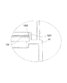
図2に開示するように、この発明によるチューブヘッド構造100は、さらに
キャップ30を含む。キャップ30の内周面には第4係合部31を形成し、連結部12の外周面には第4係合部31に係止する第3係合部124を形成する。係る構造によってキャップ30を着脱自在に冠着することができ、吐出口211に近接した位置にある内容物の湿度を保持し、外部環境の塵などの不純物の粉末による汚染から保護することができる。
As disclosed in FIG. 2, the
以上の構成によれば、チューブ本体11の封入口112から内容物を収納部111に充填して封入口112を封止することによって、内容物充填の作業を完成させることができる。
According to the above configuration, the content filling operation can be completed by filling the
また、図3に開示するように、連結部12の第1係合部122には、傾斜したガイド面1221と、係合突起部1222を形成する。ガイド面1221を形成することによって、ポンプ構造部20をチューブ構造部10に連結する場合、第2係合部221がガイド面1221に沿って順調に移動し、係合突起部1222によって第2係合部221が係合して、ポンプ構造部20が安定してチューブ構造部10に設けられる。
Further, as disclosed in FIG. 3, an
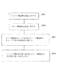
図4にこの発明によるチューブヘッド構造100を製造するステップを開示する。先ず、S01の工程においてチューブ構造物を製造に供する。該チューブ構造物は、即ち、前述するチューブ構造部10であって、チューブ本体11と、連結部12とを含んでなる。チューブ本体11は収納部111を具え、連結部12は第1係合部122を具える。
FIG. 4 discloses steps for manufacturing a
次いで、S02のステップにおいて、ポンプ構造物を製造に供する。該ポンプ構造物は、即ち前述するポンプ構造部20であって、プッシュヘッド部21と、ポンプ本体22とを含んでなり、プッシュヘッド部21は吐出口211を具え、ポンプ本体22は第2係合部221を具える。
Next, in step S02, the pump structure is subjected to manufacture. The pump structure is the above-described
次に、S03のステップにおいて、ポンプ構造部20のポンプ本体22をチューブ構造部10のチューブ本体の収納部111内に設ける。
Next, in step S <b> 03, the pump
さらに、S04のステップにおいて、チューブ構造部10の第1係合部122と、ポンプ構造部20の第2係合部221とを係合させる。チューブ構造部10のチューブ本体11と連結部12とは一体に成型され、連結部12は当止部123を具え、ポンプ部構造部20のポンプ本体22は鍔部222を具え、鍔部222が当止部123に当接する。よって、チューブ構造部10とポンプ構造部20とは、安定した連結が得られる。
Furthermore, in the step of S04, the
また、チューブ構造部10の連結部12には、ポンプ構造部20のプッシュヘッド部21を収納し、かつプッシュヘッド部21往復運動を行うための空間である収納空間121を形成する。
In addition, the connecting
当然のことながら、上述するように、この発明によるチューブヘッド構造は、さらにキャップ30を含んでもよい。この場合、キャップ30の内周面には第4係合部31を形成し、チューブ構造部10の連結部12の外周面には第4係合部31に係合する第3係合部124を形成する。
Of course, as described above, the tube head structure according to the present invention may further include a
以上はこの発明の好ましい実施の形態であって、この発明の実施の範囲を限定するものではない。よって、当業者のなし得る修正、もしくは変更であって、この発明の精神の下においてなされ、かつこの発明に対して均等の効果を有するものは、いずれもこの発明の特許請求の範囲に含まれるものとする。 The above is a preferred embodiment of the present invention, and does not limit the scope of the present invention. Accordingly, any modifications or changes that can be made by those skilled in the art, which are made within the spirit of the present invention and have an equivalent effect on the present invention, are included in the claims of the present invention. Shall.
10 チューブ構造部
100 チューブヘッド構造
11 チューブ本体
11a 第1層
11b 第2層
111 収納部
112 封入口
12 連結部
121 収納空間
122 第1係合部
1221 ガイド面
1222 係合突起部
123 当止部
124 第3係合部
20 ポンプ構造部
21 プッシュヘッド部
211 吐出口
22 ポンプ本体
221 第2係合部
222 鍔部
23 弁体
30 キャップ
31 第4係合部
DESCRIPTION OF
11b
21
Claims (10)
吐出口を具えるプッシュヘッド部と、第2係合部が形成されたポンプ本体とを有するポンプ構造部と、を含んでなり、
該第1係合部と、該第2係合部とを係合させて該ポンプ本体を該収納部内に設けることを特徴とする、ポンプ構造を有するチューブのヘッド部構造。 A tube structure comprising a tube body having a storage portion, and a connecting portion formed with a first engagement portion;
A pump structure having a push head having a discharge port, and a pump body having a second engagement portion formed thereon,
A tube head portion structure having a pump structure, wherein the pump body is provided in the storage portion by engaging the first engagement portion and the second engagement portion.
第2の工程において、吐出口を具えるプッシュヘッド部と、第2係合部を具えるポンプ本体とを含んでなるポンプ構造部を製造し、
第3の工程において、該ポンプ構造部の該ポンプ本体を該チューブ構造部の該チューブ本体の該収納部111内に設け、
第4の工程において、該チューブ構造部の該第1係合部と、該ポンプ構造部の該第2係合部とを係合させること、を特徴とするポンプ構造を有するチューブのヘッド部構造の製造方法。 In the first step, a tube structure part including a tube body having a storage part and a connecting part having a first engagement part is manufactured,
In the second step, a pump structure portion including a push head portion having a discharge port and a pump body having a second engagement portion is manufactured,
In the third step, the pump body of the pump structure part is provided in the storage part 111 of the tube body of the tube structure part,
In the fourth step, the tube head portion structure having a pump structure, wherein the first engagement portion of the tube structure portion is engaged with the second engagement portion of the pump structure portion. Manufacturing method.
Priority Applications (1)
| Application Number | Priority Date | Filing Date | Title |
|---|---|---|---|
| JP2013005326A JP2014136594A (en) | 2013-01-16 | 2013-01-16 | Head structure of tube having pump structure and production method of the same |
Applications Claiming Priority (1)
| Application Number | Priority Date | Filing Date | Title |
|---|---|---|---|
| JP2013005326A JP2014136594A (en) | 2013-01-16 | 2013-01-16 | Head structure of tube having pump structure and production method of the same |
Publications (1)
| Publication Number | Publication Date |
|---|---|
| JP2014136594A true JP2014136594A (en) | 2014-07-28 |
Family
ID=51414340
Family Applications (1)
| Application Number | Title | Priority Date | Filing Date |
|---|---|---|---|
| JP2013005326A Pending JP2014136594A (en) | 2013-01-16 | 2013-01-16 | Head structure of tube having pump structure and production method of the same |
Country Status (1)
| Country | Link |
|---|---|
| JP (1) | JP2014136594A (en) |
Citations (5)
| Publication number | Priority date | Publication date | Assignee | Title |
|---|---|---|---|---|
| JPH0319874U (en) * | 1989-08-10 | 1991-02-27 | ||
| JPH0326754U (en) * | 1989-07-21 | 1991-03-19 | ||
| JP2000153190A (en) * | 1998-11-20 | 2000-06-06 | L'oreal Sa | Pump |
| JP2010274956A (en) * | 2009-05-28 | 2010-12-09 | Yoshino Kogyosho Co Ltd | Tube container with pump |
| JP2013028350A (en) * | 2011-07-27 | 2013-02-07 | Yoshino Kogyosho Co Ltd | Liquid fixed amount spouting vessel |
-
2013
- 2013-01-16 JP JP2013005326A patent/JP2014136594A/en active Pending
Patent Citations (5)
| Publication number | Priority date | Publication date | Assignee | Title |
|---|---|---|---|---|
| JPH0326754U (en) * | 1989-07-21 | 1991-03-19 | ||
| JPH0319874U (en) * | 1989-08-10 | 1991-02-27 | ||
| JP2000153190A (en) * | 1998-11-20 | 2000-06-06 | L'oreal Sa | Pump |
| JP2010274956A (en) * | 2009-05-28 | 2010-12-09 | Yoshino Kogyosho Co Ltd | Tube container with pump |
| JP2013028350A (en) * | 2011-07-27 | 2013-02-07 | Yoshino Kogyosho Co Ltd | Liquid fixed amount spouting vessel |
Similar Documents
| Publication | Publication Date | Title |
|---|---|---|
| JP4922171B2 (en) | 2 room ampoule | |
| JP6164937B2 (en) | Airless container | |
| KR200449631Y1 (en) | Hand-operated Dropper | |
| KR200464780Y1 (en) | Storing vessel having dual structure | |
| US20160200495A1 (en) | Resin container and bag-in-box | |
| JP2014136594A (en) | Head structure of tube having pump structure and production method of the same | |
| KR101277820B1 (en) | A container with a sealing cap | |
| JP6144099B2 (en) | External air introduction mechanism of pump type spray container | |
| KR20180003252U (en) | Container For Cosmetic | |
| TWI488775B (en) | Hose assembly and manufacturing method thereof | |
| JP6366519B2 (en) | Double container | |
| JP2019059485A (en) | Lid body for liquid container | |
| KR101504014B1 (en) | A Cap of bottle and method for making thereof | |
| EP2752250B1 (en) | Collapsible tube with dispenser pump and method for manufacturing the same | |
| JP2011073756A (en) | Synthetic resin container provided with inverting, foldback bottom wall | |
| US20150284172A1 (en) | Flexible tube | |
| CN204688714U (en) | The inner bag of bag in a kind of box | |
| JP2005230167A (en) | Plastic ampule | |
| CN204726858U (en) | A kind of noresidue squeeze bottle | |
| JP7394559B2 (en) | Double container and method for manufacturing a double container | |
| JP2010017938A (en) | Injector | |
| JP6004646B2 (en) | Container with spray nozzle | |
| JP6253405B2 (en) | Dripping container | |
| GB2509531A (en) | Flexible container and pump for a liquid dispenser | |
| CN209351938U (en) | A kind of plastic mist spray bottle convenient to use |
Legal Events
| Date | Code | Title | Description |
|---|---|---|---|
| A711 | Notification of change in applicant |
Free format text: JAPANESE INTERMEDIATE CODE: A711 Effective date: 20140508 |
|
| A521 | Written amendment |
Free format text: JAPANESE INTERMEDIATE CODE: A821 Effective date: 20140508 |
|
| A977 | Report on retrieval |
Free format text: JAPANESE INTERMEDIATE CODE: A971007 Effective date: 20150114 |
|
| A131 | Notification of reasons for refusal |
Free format text: JAPANESE INTERMEDIATE CODE: A131 Effective date: 20150203 |
|
| A02 | Decision of refusal |
Free format text: JAPANESE INTERMEDIATE CODE: A02 Effective date: 20150630 |