JP2014128238A - Display case for fishing reel, and fishing reel - Google Patents
Display case for fishing reel, and fishing reel Download PDFInfo
- Publication number
- JP2014128238A JP2014128238A JP2012288548A JP2012288548A JP2014128238A JP 2014128238 A JP2014128238 A JP 2014128238A JP 2012288548 A JP2012288548 A JP 2012288548A JP 2012288548 A JP2012288548 A JP 2012288548A JP 2014128238 A JP2014128238 A JP 2014128238A
- Authority
- JP
- Japan
- Prior art keywords
- case
- display device
- display
- main body
- light guide
- Prior art date
- Legal status (The legal status is an assumption and is not a legal conclusion. Google has not performed a legal analysis and makes no representation as to the accuracy of the status listed.)
- Pending
Links
Images


Classifications
-
- A—HUMAN NECESSITIES
- A01—AGRICULTURE; FORESTRY; ANIMAL HUSBANDRY; HUNTING; TRAPPING; FISHING
- A01K—ANIMAL HUSBANDRY; CARE OF BIRDS, FISHES, INSECTS; FISHING; REARING OR BREEDING ANIMALS, NOT OTHERWISE PROVIDED FOR; NEW BREEDS OF ANIMALS
- A01K89/00—Reels
- A01K89/015—Reels with a rotary drum, i.e. with a rotating spool
-
- A—HUMAN NECESSITIES
- A01—AGRICULTURE; FORESTRY; ANIMAL HUSBANDRY; HUNTING; TRAPPING; FISHING
- A01K—ANIMAL HUSBANDRY; CARE OF BIRDS, FISHES, INSECTS; FISHING; REARING OR BREEDING ANIMALS, NOT OTHERWISE PROVIDED FOR; NEW BREEDS OF ANIMALS
- A01K89/00—Reels
- A01K89/01—Reels with pick-up, i.e. with the guiding member rotating and the spool not rotating during normal retrieval of the line
- A01K89/01121—Frame details
Landscapes
- Life Sciences & Earth Sciences (AREA)
- Environmental Sciences (AREA)
- Animal Husbandry (AREA)
- Biodiversity & Conservation Biology (AREA)
- Slot Machines And Peripheral Devices (AREA)
Abstract
Description
本発明は、釣用リールの表示ケース、及び釣用リールに関する。 The present invention relates to a fishing reel display case and a fishing reel.
従来の釣用リールでは、表示ケースを備えたものがある(特許文献1を参照)。表示ケースは、主に、表示装置(14)と、基板(15)と、外装材(10、10B)とを、有している。この表示ケースでは、基板(15)が、外装材(10、10B)に配置され、ネジ部材で固定されている。また、基板上には、緩衝材(16)を介して、表示装置(14)が装着されている。また、表示装置(14)は、基板上に設けられた支持部材(14A)によって、左右の方向の位置決めが行われている。 Some conventional fishing reels include a display case (see Patent Document 1). The display case mainly includes a display device (14), a substrate (15), and an exterior material (10, 10B). In this display case, the substrate (15) is disposed on the exterior material (10, 10B) and fixed with a screw member. Further, a display device (14) is mounted on the substrate via a cushioning material (16). The display device (14) is positioned in the left-right direction by a support member (14A) provided on the substrate.
従来の表示ケースでは、表示装置(緩衝材を含む)が基板上に配置されていた。このため、基板には、表示装置を配置するためのスペース、及び表示装置を位置決めするための支持部材を配置するためのスペースを、用意する必要があった。すなわち、従来の構成では、上記のスペースを確保するために、基板の大きさが大きくなってしまうおそれがある。このため、基板まわりの構成、すなわち基板を覆う表示ケースが、大きくなってしまうおそれがあった。 In a conventional display case, a display device (including a buffer material) is disposed on a substrate. For this reason, it is necessary to prepare a space for arranging a display device and a space for arranging a support member for positioning the display device on the substrate. That is, in the conventional configuration, there is a possibility that the size of the substrate becomes large in order to secure the above-described space. For this reason, the configuration around the substrate, that is, the display case covering the substrate may be large.
本発明は、上記の問題に鑑みてなされたものであって、本発明の目的は、表示ケースの小型化を図ることにある。 The present invention has been made in view of the above problems, and an object of the present invention is to reduce the size of the display case.
発明1に係る釣用リールの表示ケースは、表示装置と、ケース本体と、パネル部材とを、備えている。ケース本体は、開口部と、複数の支持部とを、有している。開口部には、表示装置の少なくとも一部が、配置される。複数の支持部は、表示装置の外周部を支持するためのものである。パネル部材は、表示装置の表示側において、ケース本体に装着される。 A fishing reel display case according to a first aspect includes a display device, a case body, and a panel member. The case body has an opening and a plurality of support portions. At least a part of the display device is disposed in the opening. The plurality of support portions are for supporting the outer peripheral portion of the display device. The panel member is attached to the case body on the display side of the display device.
この表示ケースでは、表示装置の少なくとも一部が開口部に配置されるように、表示装置の外周部がケース本体の複数の支持部に支持されている。このように、この表示ケースでは、表示装置が、基板に固定されるのではなく、ケース本体に固定されているので、基板上に上記のスペースを確保する必要がなくなる。これにより、基板を小型化することができる。すなわち、表示ケースを、小型化することができる。 In this display case, the outer peripheral portion of the display device is supported by a plurality of support portions of the case body so that at least a part of the display device is disposed in the opening. Thus, in this display case, since the display device is not fixed to the substrate, but is fixed to the case body, it is not necessary to secure the space on the substrate. Thereby, a board | substrate can be reduced in size. That is, the display case can be reduced in size.
また、表示装置を基板に固定する従来技術では、基板の面積の制約から、表示装置を大型化することが難しい。しかしながら、この表示ケースでは、表示装置を基板に固定するのではなく、ケース本体に固定しているので、表示装置を大型化することができる。 In the conventional technique for fixing the display device to the substrate, it is difficult to increase the size of the display device due to the limitation of the area of the substrate. However, in this display case, since the display device is not fixed to the substrate, but is fixed to the case body, the display device can be enlarged.
発明2に係る釣用リールの表示ケースでは、発明1に記載の表示ケースにおいて、表示装置の外周部が、複数の支持部とケース本体との間に配置される。この場合、表示装置の外周部が、複数の支持部とケース本体との間に配置されるので、表示装置をケース本体に確実に固定することができる。 In the fishing reel display case according to a second aspect, in the display case according to the first aspect, the outer peripheral portion of the display device is disposed between the plurality of support portions and the case main body. In this case, since the outer peripheral portion of the display device is disposed between the plurality of support portions and the case main body, the display device can be reliably fixed to the case main body.
発明3に係る釣用リールの表示ケースでは、発明1又は2に記載の表示ケースにおいて、複数の支持部の少なくともいずれか1つが、雌ねじ部と、雌ねじ部に螺合されるボルト部材とを、有している。この場合、上記の少なくとも1つの支持部の雌ねじ部に、ボルト部材が螺合されるので、表示装置をケース本体により確実に固定することができる。
In the display case of the fishing reel according to the
発明4に係る釣用リールの表示ケースでは、発明1から3のいずれか1項に記載の表示ケースにおいて、表示装置の外周部が、凹部を有している。凹部は、複数の支持部の少なくともいずれか1つに係合する。この場合、表示装置の外周部の凹部が、複数の支持部の少なくともいずれか1つに係合するので、表示装置をケース本体に確実に位置決めすることができる。 The fishing reel display case according to a fourth aspect of the present invention is the display case according to any one of the first to third aspects, wherein the outer peripheral portion of the display device has a recess. The recess engages with at least one of the plurality of support portions. In this case, since the concave portion of the outer peripheral portion of the display device engages with at least one of the plurality of support portions, the display device can be reliably positioned on the case body.
発明5に係る釣用リールの表示ケースでは、発明1から4のいずれか1項に記載の表示ケースにおいて、表示装置が、表示部と、表示部に光を導光する導光部とを、有している。表示装置の外周部は、導光部の外周部である。表示部は、パネル部材と導光部との間において、開口部に配置される。この場合、導光部の外周部が、複数の支持部によって支持される。また、表示部は、パネル部材と導光部との間において、開口部に配置される。このように、導光部及び表示部を配置することによって、表示ケースの厚みを薄くすることができる。
In the display case of the fishing reel according to the
発明6に係る釣用リールの表示ケースでは、発明5に記載の表示ケースにおいて、表示装置が、導光部を補強する補強部を、さらに有している。表示装置の外周部は、導光部の外周部及び補強部の外周部である。この場合、導光部の剛性が小さくても、補強部が導光部を補強しているので、導光部の外周部を、複数の支持部によって確実に支持することができる。 In the fishing reel display case according to a sixth aspect of the invention, in the display case according to the fifth aspect, the display device further includes a reinforcing portion that reinforces the light guide portion. The outer peripheral part of the display device is the outer peripheral part of the light guide part and the outer peripheral part of the reinforcing part. In this case, even if the rigidity of the light guide portion is small, the reinforcing portion reinforces the light guide portion, so that the outer peripheral portion of the light guide portion can be reliably supported by the plurality of support portions.
発明7に係る釣用リールの表示ケースでは、発明5又は6に記載の表示ケースにおいて、ケース本体が、パネル部材を装着するためのパネル装着部を、有している。パネル装着部の外形は、多角形状に形成されている。パネル装着部の外周に近い開口部の隅角部は、隅切りされている。 In the display case of the fishing reel according to the seventh aspect, in the display case according to the fifth or sixth aspect, the case main body has a panel mounting portion for mounting a panel member. The outer shape of the panel mounting part is formed in a polygonal shape. The corner portion of the opening near the outer periphery of the panel mounting portion is cut off.
この場合、ケース本体には、多角形状のパネル装着部が設けられている。このパネル装着部の外周に近い位置に存在する開口部の隅角部は、隅切りされている。これにより、パネル装着部の外周と、開口部の隅角部との間の間隔を、大きくすることができる。これにより、パネル部材とパネル装着部の外周との隙間からの異物(水を含む)の侵入を、確実に防止することができる。 In this case, the case body is provided with a polygonal panel mounting portion. The corners of the opening existing at a position close to the outer periphery of the panel mounting part are cut off. Thereby, the space | interval between the outer periphery of a panel mounting part and the corner part of an opening part can be enlarged. Thereby, the penetration | invasion of the foreign material (water is included) from the clearance gap between a panel member and the outer periphery of a panel mounting part can be prevented reliably.
発明8に係る釣用リールの表示ケースは、発明1から7のいずれか1項に記載の表示ケースにおいて、表示装置を制御するための制御基板を、さらに備えている。ケース本体は、第1本体部材と、第2本体部材とを、有している。第1本体部材は、上記の開口部と、上記の複数の支持部とを、有している。第2本体部材は、第1本体部材に装着される。第2本体部材には、制御基板が配置される。パネル部材は、第1本体部材に配置される。 A display case for a fishing reel according to an eighth aspect of the present invention is the display case according to any one of the first to seventh aspects, further comprising a control board for controlling the display device. The case body has a first body member and a second body member. The 1st main body member has the above-mentioned opening and a plurality of above-mentioned support parts. The second body member is attached to the first body member. A control board is disposed on the second body member. The panel member is disposed on the first main body member.
この場合、第1本体部材が、上記の開口部と上記の複数の支持部とを有しているので、表示装置は、第1本体部材に配置される。また、第2本体部材には、制御基板が配置される。これにより、本表示ケースでは、従来技術のように基板上に表示装置用のスペースを確保する必要がないので、基板を小型化することができる。すなわち、表示ケースを、小型化することができる。 In this case, since the 1st main body member has the above-mentioned opening and a plurality of above-mentioned support parts, a display is arranged at the 1st main body member. A control board is disposed on the second body member. Thereby, in this display case, since it is not necessary to ensure the space for display apparatuses on a board | substrate like the prior art, a board | substrate can be reduced in size. That is, the display case can be reduced in size.
発明9に係る釣用リールでは、請求項1から8のいずれか1項に記載の表示ケースを有するリール本体と、リール本体に回転自在に装着されるハンドルと、ハンドルの回転によって釣り糸が巻き付けられるスプールとを、備えている。
In the fishing reel according to the ninth aspect, the reel body having the display case according to any one of
この釣用リールでは、表示ケースが、発明1から7のいずれか1項に記載の表示ケースになっている。これにより、表示ケースの小型化を図ることができる。すなわち、釣用リールの小型化を図ることができる。 In this fishing reel, the display case is the display case according to any one of the first to seventh aspects. Thereby, size reduction of a display case can be achieved. That is, the fishing reel can be downsized.
本発明によれば、表示ケースの小型化を図ることができる。 According to the present invention, the display case can be reduced in size.
<全体構成>
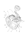
本発明の一実施形態を採用した電動リール10は、釣り糸を前方に繰り出す。電動リール10は、図1及び図2に示すように、主に、ハンドル1と、リール本体2と、スプール3と、モータ4と、カウンタケース5(表示ケースの一例)とを、備えている。ハンドル1は、リール本体2に装着されている。スプール3は、リール本体2に回転自在に装着されている。モータ4は、スプール3に内蔵されている。カウンタケース5は、水深表示等を行うためのものであり、リール本体2の上部に装着されている。リール本体2の内部には、ハンドル1の回転及びモータ4の回転をスプール3に伝達する回転伝達機構6が、設けられている(図3を参照)。
<Overall configuration>
The
<リール本体の構成>
リール本体2は、図1及び図2に示すように、フレーム13と、フレーム13の両側を覆う第1側カバー14及び第2側カバー15と、上カバー16と、前カバー17と、を有している。
<Structure of reel body>
As shown in FIGS. 1 and 2, the
上カバー16は、フレーム13と、第1側カバー14及び第2側カバー15との間に配置され、且つ第1側カバー14及び第2側カバー15との上部に、配置されている。また、上カバー16は、第1側カバー14及び第2側カバー15に対して、前後方向及び左右方向に沿うように、第1側カバー14及び第2側カバー15に装着されている。
The
前カバー17は、フレーム13の前方を覆っている。フレーム13は、アルミニウムダイキャスト製の一体成形された部材であり、第1側板13a及び第2側板13bと、連結部材13cとを、有している。
The
第1側板13aには、円形の第1開口13dが形成されている。第1開口13dには、モータホルダ7が装着されている。第1側板13aの第1開口13dの周囲には、周方向に間隔を隔てて、複数(例えば6個)の貫通孔(図示しない)が形成されている。貫通孔は、モータホルダ7を第1側板13aに固定するために使用される。
A circular
第2側板13bには、円形の第2開口13eが形成されている。第2開口13eには、回転伝達機構6を含む各種の機構を装着するための機構装着板19が、装着されている。第1側カバー14は、ハンドル1と逆側に配置され、第1側板13aの外方を覆っている。
A circular
連結部材13cは、第1側板13a及び第2側板13bを複数箇所で連結する。
The connecting
第1側カバー14は、カバー本体14aと、冷却カバー14bと、を有している。冷却カバー14bは、カバー本体14aのモータ配置部分に装着される。冷却カバー14bは、モータ4の冷却用のスリット14cを、有している。
The
第2側カバー15は、ハンドル1装着側に配置され、第2側板13bの外方を覆っている。機構装着板19は、第2側板13bと、第2側カバー15との間に配置されている。機構装着板19の中心部には、スプール3を支持するための軸受44が装着される。
The
上部の連結部材13cには、カウンタケース5が装着するためのケース受部113c(図1を参照)が、設けられている。カウンタケース5は、固定部材例えばネジ部材を、ケース受部113cの雌ネジ部113dに螺合することによって、ケース受部113cに、装着される。下部の連結部材13cには、釣り竿を装着するための竿装着脚18が、設けられている。
The upper connecting
<スプールの構成>
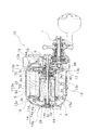
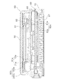
スプール3は、図2に示すように、釣り糸が巻回される糸巻胴部3aと、糸巻胴部3aの両端に一体形成された第1フランジ部3b及び第2フランジ部3cとを、有している。糸巻胴部3aは、中空に形成されている。糸巻胴部3aの内部には、収納空間3dと、遊星収納空間3eとが、形成されている。モータ収納空間3dには、モータ4が収納される。遊星収納空間3eには、回転伝達機構6を構成する遊星減速機構40が、収納される。遊星減速機構40は、モータ4の回転を減速してスプール3に伝達する。スプール3の一端(図2の左側)は、軸受42によって、モータ4(後述するモータケース20)に回転自在に支持されている。スプール3の他端(図3の右端)には、回転支持用の固定板46が固定されている。固定板46は、軸受44によって、リール本体2の機構装着板19に回転自在に支持される。
<Spool configuration>
As shown in FIG. 2, the
<モータの構成>
モータ4は、例えば、ブラシレスモータである。図2に示すように、モータ4は、モータケース20と、モータケース20の内周面に設けられた固定子22と、固定子22の内周側に配置された回転子24と、回転子が固定された出力軸26と、を有している。モータケース20は、耐食性を高めるためにアルマイト処理されたアルミニウム合金製の部材である。
<Configuration of motor>
The
モータケース20は、固定子22と回転子24とを、覆うケースである。モータケース20には、出力軸26を回転自在に支持する軸受30が、装着されている。固定子22は、モータケース20の内周部に固定されている。固定子22は、図示しない、複数(例えば3個)の積層コアと積層コアに巻回されるコイルと、を有している。回転子24は、出力軸26に一体回転可能に取り付けられている。
The
出力軸26には、回転子24が装着される。出力軸26は、モータケース20に装着された軸受30と、モータホルダ7に装着された軸受32と、によって支持される。出力軸26の一端(図3の左側)には、出力軸26の糸繰り出し方向の回転を禁止するためのワンウェイクラッチ34が、装着されている。出力軸26の他端(図3の右側)には、回転伝達機構6を構成する遊星減速機構40が、装着されている。
A
<カウンタケース>
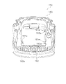
図1−4に示すように、カウンタケース5は、ケース本体50と、表示装置51と、フロントパネル52(パネル部材の一例)とを、有している。
<Counter case>
As illustrated in FIG. 1-4, the
ケース本体50は、フレーム13に装着される。具体的には、ケース本体50は、フレーム13に、固定部材例えばネジ部材(図示しない)を介して、固定される。より具体的には、ケース本体50は、上カバー16と、第1側カバー14及び第2側カバー15との間において、上部の連結部材13cのケース受部113c(雌ネジ部113d)に、固定部材例えばネジ部材(図示しない)を介して、固定される。
The
ケース本体50は、第1本体部材60と、第2本体部材70とを、有している。第1本体部材60は、ケース本体50の上部を構成する部材である。第1本体部材60は、第2本体部材70の上部に装着される。具体的には、第1本体部材60は、第2本体部材70に嵌め込み装着される。これにより、第1本体部材60と第2本体部材70との間には、表示装置51及び制御基板98を配置するための空間が、形成される。
The case
図3及び図4に示すように、第1本体部材60が第2本体部材70に装着された状態において、カウンタケース5(第1本体部材60及び第2本体部材70)は、上述したように、第2本体部材70に形成されたネジ孔部70fを介して、フレーム13に固定される。また、この状態において、カウンタケース5(第1本体部材60及び第2本体部材70)は、第2本体部材70に形成されたネジ孔部70gを介して、ネジ部材(図示しない)によって、上カバー16に固定される。
As shown in FIGS. 3 and 4, the counter case 5 (the first
第1本体部材60は、本体部60aと、パネル装着部60bと、3つの釦孔60cと、開口部60dと、複数の支持部60eと、を、有している。本体部60aの上面には、パネル装着部60bが形成されている。図3及び図6に示すように、パネル装着部60bは、パネル装着面160bと枠部260bとを、有している。パネル装着面160bには、フロントパネル52が、接着剤によって、装着される。
The first
パネル装着面160bの外形は、多角形状に形成されている。具体的には、パネル装着面160bの外形は、実質的に台形状に形成されている。パネル装着面160bの外周部には、枠部260bが形成されている。枠部260bは、パネル装着面160bの外周部から外方に突出している。すなわち、枠部260bは、実質的に台形状に形成されている。3つの釦孔60cには、操作釦が配置される。
The outer shape of the
図4に示すように、開口部60dは、パネル装着面160bに形成されている。開口部60dは、実質的に矩形状に形成されている。開口部60dの4つの隅角部260dの中の2つの隅角部261dは、隅切りされている。これら2つの隅角部261d(隅切り部)は、前方側の隅角部である。具体的には、これら2つの隅角部261dは、他の2つの隅角部よりパネル装着部60bの外周に近い隅角部である。より具体的には、これら2つの隅角部261dは、他の2つの隅角部260dより、パネル装着面160bの枠部260bに近い隅角部である。開口部60dには、表示装置51の少なくとも一部、例えば後述するLCD91(Liquid Crystal Monitor)が、配置される。
As shown in FIG. 4, the
図4−図6に示すように、複数の支持部60eは、表示装置51の外周部を支持する部分である。複数の支持部60e、例えば3つの支持部が、開口部60dの近傍において、第1本体部材60に一体に形成されている。具体的には、3つの支持部60eの中の2つの支持部(第1支持部61e)が、開口部60dの一辺を構成する第1縁部161dに、一体に形成されている。2つの第1支持部61eそれぞれは、鉤状に形成されている。言い換えると、2つの第1支持部61eそれぞれは、実質的にL字状に形成されている。2つの第1支持部61eそれぞれは、基端部71eと、先端部72eとを、有している。基端部71eは、第1縁部161dから、パネル装着部60bとは反対側に向けて延びる部分である。先端部72eは、基端部71eの先端に一体に形成されており、基端部71eの先端から開口部60dの開口側に向けて延びる部分である。
As illustrated in FIGS. 4 to 6, the plurality of
また、図4−図6に示すように、3つの支持部60eの中の1つの支持部(第2支持部62e)は、パネル装着部60bの反対側の面に一体に形成されている。この第2支持部62eは、雌ねじ部81eとボルト部材82eとを、有している。ボルト部材82eは、雌ねじ部81eの雌ねじに螺合される。
Moreover, as shown in FIGS. 4-6, one support part (
第2本体部材70は、ケース本体50の下部を構成する部材である。図3及び図6に示すように、第2本体部材70には、制御基板98と、モータ制御用の基板99と、ヒートシンク97とが、装着されている。制御基板98は、リール全体を統括制御する。制御基板98には、フレキシブルプリント基板(図示しない)の一端部が接続される。また、フレキシブルプリント基板の他端部は、表示装置51に接続される。
The second
例えば、制御基板98は、LCD91及び光源95を制御する。制御基板98には、図5に示すように、導光板92(導光部の一例)に光を照射するための光源95が、配置されている。光源95は、制御基板98からの信号に基づいて、光の照射タイミング及び照射時間が、制御される。図5では、光源95の位置を説明するために、光源95を第1本体部材60上で破線にて示している。
For example, the
モータ用の基板99には、例えば、FET(Field effect transistor)を含むモータ駆動回路が、配置されている。FETは、デューティ比に応じてスイッチングするスイッチ素子として機能する。また、FETは、例えば、モータ4の固定子22のコイルを順に励磁及び消磁するためのスイッチ素子として機能する。
For example, a motor drive circuit including a field effect transistor (FET) is disposed on the
ヒートシンク97は、第1本体部材60及び第2本体部材70との間の空間の熱を、放熱する。ヒートシンク97は、モータ用の基板99の下方において、第2本体部材70に装着されている。
The
表示装置51は、水深表示等を行うためのものである。表示装置51は、フレキシブルプリント基板を介して、制御基板98からの信号を受け取り、この信号に基づいて、水深表示等を行う。表示装置51は、外周部において、3つの支持部60e、例えば2つの第1支持部61e及び1つの第2支持部62eによって、支持される。表示装置51の外周部は、第1支持部61e及び第2支持部62eと、ケース本体50との間に、配置される。
The
図3及び図5−7に示すように、表示装置51は、LCD91(Liquid Crystal Monitor)と、導光板92とを、有している。LCD91は、液晶パネルであり、制御基板98からの信号を受けて、情報を表示する。図7に示すように、LCD91は、実質的に矩形状に形成されている。LCD91の4つの隅角部191の中の2つの隅角部191a(面取り部)は、面取りされている。LCD91の面取り部191aが開口部60dの隅切り部261d(図3及び図4を参照)に対向するように、LCD91は、開口部60dに配置される。また、LCD91は、導光板92と、後述するフロントパネル52との間において、開口部60dに配置される。
As shown in FIGS. 3 and 5-7, the
図4−5及び図8に示すように、導光板92は、光源95からの光を、LCD91に導くためのものである。図8に示すように、導光板92は、実質的に矩形状に形成されている。導光板92の外周部、例えば導光板92の一辺には、2つの第1凹部92aが形成されている。導光板92の第1凹部92aは、第1支持部61eに係合する。具体的には、導光板92の第1凹部92aは、第1支持部61eの基端部71eに嵌合される。また、導光板92の外周部、例えば上記の導光板92の一辺に対向する辺には、1つの第2凹部92bが形成されている。導光板92の第2凹部92bは、第2支持部62eに係合する(図4を参照)。具体的には、導光板92の第2凹部92bには、第2支持部62eの雌ねじ部81eが配置される。
As shown in FIGS. 4-5 and 8, the
このように、第1凹部92a及び第2凹部92bを、第1支持部61e及び第2支持部62eに係合させることによって、導光板92(表示装置51)が、第1本体部材60(ケース本体50)に位置決めされる。この状態で、ボルト部材82eを雌ねじ部81eの雌ねじに螺合することによって、導光板92(表示装置51)が、第1本体部材60(ケース本体50)に固定される。これにより、導光板92の外周部は、第1支持部61eの先端部72e及び第2支持部62eのボルト部材82eの頭部と、第1本体部材60のパネル装着部60bの背面との間に、配置され、支持される。
In this way, by engaging the
すなわち、表示装置51の外周部(導光板92)は、第1支持部61e及び第2支持部62eと、ケース本体50との間に配置された状態で、第1支持部61e及び第2支持部62eによって支持される。
That is, the outer peripheral part (light guide plate 92) of the
図3及び図6に示すように、フロントパネル52は、LCD91を覆うパネルである。また、フロントパネル52は、光を透過するパネルである。フロントパネル52は、表示装置51の表示側において、ケース本体50の第1本体部材60に、装着される。具体的には、フロントパネル52は、第1本体部材60のパネル装着部60bに、接着剤例えば両面テープによって、装着される。これにより、フロントパネル52と導光板92との間において、LCD91が開口部60dに配置される。なお、図3では、フロントパネル52を、破線で表示している。
As shown in FIGS. 3 and 6, the
<カウンタケースの組み立て>
本カウンタケース5では、まず、導光板92が、第1本体部材60に装着される。具体的には、導光板92の2つの第1凹部92aが、第1本体部材60における2つの第1支持部61eに、嵌合される。また、導光板92の第1凹部92aを第1本体部材60の第1支持部61eに嵌合した状態で、導光板92の第2凹部92bが、第1本体部材60における第2支持部62eの雌ねじ部81eに、配置される。この状態で、ボルト部材82eが、第2支持部62eの雌ねじ部81eに形成された雌ねじに、螺合される。これにより、導光板92が、複数の支持部(第1支持部61e及び第2支持部62e)と、第1本体部材60との間に配置される。次に、LCD91が、第1本体部材60の開口部60dに嵌め込まれ、導光板92の上に配置される。続いて、フロントパネル52が、第1本体部材60のパネル装着部60bに装着される。続いて、フレキシブルプリント基板を介して、第2本体部材70に装着された制御基板98のコネクタ(図示しない)と、第1本体部材60に装着されたLCD91のコネクタ91a(図5及び図7を参照)とが、接続される。最後に、この状態で、第1本体部材60が、第2本体部材70に装着される。
<Assembly of counter case>
In the
<まとめ>
(1)本カウンタケース5は、表示装置51と、ケース本体50(第1本体部材60)と、フロントパネル52(パネル部材)とを、備えている。ケース本体50は、開口部60dと、複数の支持部60eとを、有している。開口部60dには、表示装置51の少なくとも一部、例えばLCD91が、配置される。複数の支持部60e(第1支持部61e及び第2支持部62e)は、表示装置51の外周部を支持するためのものである。フロントパネル52は、表示装置51の表示側において、ケース本体50に装着される。
<Summary>
(1) The
このカウンタケース5では、LCD91が開口部60dに配置されるように、表示装置51の外周部が複数の支持部60eに支持されている。このように、このカウンタケース5では、表示装置51を、制御基板98に固定するのではなく、ケース本体50に固定しているので、制御基板98上に上記のスペースを確保する必要がなくなる。これにより、制御基板98を小型化することができる。すなわち、制御基板98を覆うカウンタケース5を、小型化することができる。
In the
(2)本カウンタケース5では、表示装置51の外周部が、第1支持部61e及び第2支持部62e(複数の支持部)と第1本体部材60(ケース本体50)との間に配置される。この場合、表示装置51の外周部が、第1支持部61e及び第2支持部62eと第1本体部材60との間に配置されるので、表示装置51をケース本体50に確実に固定することができる。
(2) In the
(3)本カウンタケース5では、第1支持部61e及び第2支持部62e(複数の支持部)の少なくともいずれか1つが、雌ねじ部81eと、雌ねじ部81eに螺合されるボルト部材82eとを、有している。前記実施形態では、第1支持部61e及び第2支持部62eの少なくともいずれか1つは、第2支持部62eに対応している。この場合、第2支持部62eの雌ねじ部81eに、ボルト部材82eが螺合されるので、表示装置51をケース本体50により確実に固定することができる。
(3) In the
(4)本カウンタケース5では、表示装置51の外周部が、第1凹部92a及び第2凹部92bを、有している。第1凹部92a及び第2凹部92bは、第1支持部61e及び第2支持部62eに係合している。このように、表示装置51の外周部の第1凹部92a及び第2凹部92bが、第1支持部61e及び第2支持部62eに係合するので、表示装置51をケース本体50に確実に位置決めすることができる。
(4) In the
(5)本カウンタケース5では、表示装置51が、LCD91と、LCD91に光を導光する導光板92(導光部)とを、有している。LCD91は、フロントパネル52と導光板92との間において、開口部60dに配置される。この場合、導光板92の外周部が、第1支持部61e及び第2支持部62eによって、支持されている。また、LCD91は、フロントパネル52と導光板92との間において、開口部60dに配置される。このように、導光板92及びLCD91を配置することによって、カウンタケース5の厚みを薄くすることができる。
(5) In the
(6)本カウンタケース5では、第1本体部材60(ケース本体50)が、フロントパネル52を装着するためのパネル装着部60bを、有している。パネル装着部60bの外形は、多角形状に形成されている。具体的には、パネル装着部60bの外形は、実質的に台形状に形成されている。パネル装着部60bの外周に近い開口部60dの隅角部261dは、隅切りされている。
(6) In the
この場合、第1本体部材60には、例えば、台形状のパネル装着部60bが設けられている。このパネル装着部60bの外周に近い位置に存在する開口部60dの隅角部261dは、隅切りされている。具体的には、このパネル装着部60bの台形の脚に近い位置に存在する開口部60dの隅角部261dは、隅切りされている。これにより、パネル装着部60bの外周と、開口部60dの隅角部261dとの間の間隔D1(図3を参照)を、大きくすることができる。これにより、フロントパネル52とパネル装着部60bの外周との隙間からの異物(水を含む)の侵入を、確実に防止することができる。
In this case, the first
(7)本電動リール10は、表示装置51を制御するための制御基板98を、さらに備えている。制御基板98は、第2本体部材70に配置される。
(7) The
この場合、表示装置51は第1本体部材60に配置され、制御基板98は第2本体部材70に配置される。これにより、従来技術のように基板上に表示装置用のスペースを確保する必要がないので、基板を小型化することができる。すなわち、表示ケースを、小型化することができる。
In this case, the
(8)本電動リール10は、上記のカウンタケース5を有するリール本体2と、リール本体に回転自在に装着されるハンドル1と、ハンドル1の回転によって釣り糸が巻き付けられるスプール3とを、備えている。この電動リール10では、上記のようなカウンタケース5を有しているので、カウンタケース5の小型化を図ることができる。すなわち、電動リール10の小型化を図ることができる。
(8) The
<他の実施形態>
以上、本発明の一実施形態について説明したが、本発明は上記実施形態に限定されるものではなく、発明の要旨を逸脱しない範囲で種々の変更が可能である。特に、本明細書に書かれた複数の実施形態及び変形例は必要に応じて、任意に組合せ可能である。
<Other embodiments>
As mentioned above, although one Embodiment of this invention was described, this invention is not limited to the said embodiment, A various change is possible in the range which does not deviate from the summary of invention. In particular, a plurality of embodiments and modifications described in the present specification can be arbitrarily combined as necessary.
(A)前記実施形態では、表示装置51が、LCD91と導光板92とを有している場合の例を示したが、図9に示すように、表示装置51が、導光板92を補強する補強板93(補強部の一例)を、さらに有していてもよい。この場合、補強板93の外周部には、表示装置51の外周部と同様に、第1凹部92aに対応する凹部93aと、第2凹部92bに対応する凹部(図示しない)が、形成される。これにより、導光板92の外周部及び補強板93の外周部を、第1支持部61e及び第2支持部62eに支持させることができる。この場合、導光板92の剛性が小さくても、導光板92が補強板93によって補強されるので、導光板92を、第1支持部61e及び第2支持部62eによって、確実に支持することができる。
(A) In the above embodiment, an example in which the
(B)前記実施形態では、表示装置51が、2つの第1支持部61e及び1つの第2支持部62eによって支持される場合の例を示したが、表示装置151が、複数の支持部、例えば3つの第1支持部161eによって、支持されるようにしてもよい。この場合、例えば、図10に示すように、導光板192には、3つの第1凹部192aが形成される。また、第1本体部材160(ケース本体150)には、3つの第1支持部161eが形成される。
(B) In the said embodiment, although the example in the case where the
3つの第1凹部192aそれぞれは、対応する第1支持部161eに嵌合される。具体的には、まず、導光板192の2つの第1凹部192aが、第1本体部材160における2つの第1支持部161eに、嵌合される。また、これら2つの第1凹部192aを、第1本体部材160の第1支持部161eに嵌合した状態で、導光板192を弾性変形させて、他の第1凹部192aが、他の第1本体部材160の第1支持部161eに嵌合される。これにより、導光板192が、3つの第1支持部161eと、第1本体部材160との間に配置される。このように、本実施形態では、表示装置151をケース本体150により容易に装着することができる。なお、この場合も、他の実施形態(A)の補強板193によって、導光板192を補強するようにしてもよい。
Each of the three
本発明は、釣用リールのケース本体、及び釣用リールに対して、広く適用可能である。 The present invention can be widely applied to a case main body of a fishing reel and a fishing reel.
100 スピニングリール
1 ハンドル
2 リール本体
3 ロータ
4 スプール
5 カウンタケース
50 ケース本体
51 表示装置
52 フロントパネル
60 第1本体部材
60b パネル装着部
60d 開口部
60e 支持部
61e 第1支持部
62e 第2支持部
81e 雌ねじ部
82e ボルト部材
91 LCD
92 導光板
92a 第1凹部
92b 第2凹部
93 補強板
161e 第1支持部
192 導光板
192a 第1凹部
261d 隅角部
DESCRIPTION OF SYMBOLS 100
92
Claims (9)
表示装置 と、
前記表示装置の少なくとも一部 が配置される開口部と、前記表示装置の外周部を支持するための複数の支持部とを、有するケース本体と、
前記表示装置の表示側において前記ケース本体に装着されるパネル部材と、
を備えた表示ケース。 A fishing reel display case,
A display device;
A case body having an opening in which at least a part of the display device is disposed, and a plurality of support portions for supporting an outer peripheral portion of the display device;
A panel member attached to the case body on the display side of the display device;
Display case with.
請求項1に記載の表示ケース。 The outer peripheral portion of the display device is disposed between a plurality of the support portions and the case body.
The display case according to claim 1.
請求項1又は2に記載の表示ケース。 At least one of the plurality of support portions includes a female screw portion and a bolt member screwed into the female screw portion.
The display case according to claim 1 or 2.
請求項1から3のいずれか1項に記載の表示ケース。 The outer peripheral portion of the display device has a recess that engages with at least one of the plurality of support portions.
The display case according to claim 1.
前記表示装置の外周部は、前記導光部の外周部であり、
前記表示部は、前記パネル部材と前記導光部との間において、前記開口部に配置される、
請求項1から4のいずれか1項に記載の表示ケース。 The display device includes a display unit, and a light guide unit that guides light to the display unit,
The outer peripheral part of the display device is the outer peripheral part of the light guide part,
The display unit is disposed in the opening between the panel member and the light guide unit.
The display case according to claim 1.
前記表示装置の外周部は、前記導光部の外周部及び前記補強部の外周部である、
請求項5に記載の表示ケース。 The display device further includes a reinforcing portion that reinforces the light guide portion,
The outer peripheral part of the display device is the outer peripheral part of the light guide part and the outer peripheral part of the reinforcing part,
The display case according to claim 5.
前記パネル装着面の外形は、多角形状に形成されており、
前記パネル装着部の外周に近い前記開口部の隅角部は、隅切りされている、
請求項5又は6に記載の表示ケース。 The case body has a panel mounting surface for mounting the panel member,
The outer shape of the panel mounting surface is formed in a polygonal shape,
The corner of the opening close to the outer periphery of the panel mounting part is cut off.
The display case according to claim 5 or 6.
をさらに備え、
前記ケース本体は、前記開口部と複数の前記支持部とを有する第1本体部材と、前記第1本体部材に装着され前記第1本体部材との間に内部空間を形成し前記制御基板が配置される第2本体部材とを、有し、
前記パネル部材は、前記第1本体部材に配置される、
請求項1から7のいずれか1項に記載の表示ケース。 A control board for controlling the display device;
Further comprising
The case main body has a first main body member having the opening and the plurality of support portions, and an inner space is formed between the first main body member and the first main body member, and the control board is disposed. A second body member to be
The panel member is disposed on the first body member.
The display case according to claim 1.
前記表示ケースが装着されるリール本体と、
前記リール本体に回転自在に装着されるハンドルと、
前記ハンドルの回転によって釣り糸が巻き付けられるスプールと、
を備える釣用リール。 The display case according to any one of claims 1 to 8,
A reel body to which the display case is mounted;
A handle rotatably mounted on the reel body;
A spool around which a fishing line is wound by rotation of the handle;
Fishing reel with
Priority Applications (4)
| Application Number | Priority Date | Filing Date | Title |
|---|---|---|---|
| JP2012288548A JP2014128238A (en) | 2012-12-28 | 2012-12-28 | Display case for fishing reel, and fishing reel |
| KR1020130100919A KR20140086806A (en) | 2012-12-28 | 2013-08-26 | Display case for fishing reel and fishing reel |
| TW102132985A TWI580351B (en) | 2012-12-28 | 2013-09-12 | Display case for fishing reel and fishing reel with the case |
| CN201310707189.3A CN103907576A (en) | 2012-12-28 | 2013-12-20 | Display housing of fishing reel and fishing reel |
Applications Claiming Priority (1)
| Application Number | Priority Date | Filing Date | Title |
|---|---|---|---|
| JP2012288548A JP2014128238A (en) | 2012-12-28 | 2012-12-28 | Display case for fishing reel, and fishing reel |
Publications (2)
| Publication Number | Publication Date |
|---|---|
| JP2014128238A true JP2014128238A (en) | 2014-07-10 |
| JP2014128238A5 JP2014128238A5 (en) | 2016-01-14 |
Family
ID=51033852
Family Applications (1)
| Application Number | Title | Priority Date | Filing Date |
|---|---|---|---|
| JP2012288548A Pending JP2014128238A (en) | 2012-12-28 | 2012-12-28 | Display case for fishing reel, and fishing reel |
Country Status (4)
| Country | Link |
|---|---|
| JP (1) | JP2014128238A (en) |
| KR (1) | KR20140086806A (en) |
| CN (1) | CN103907576A (en) |
| TW (1) | TWI580351B (en) |
Families Citing this family (1)
| Publication number | Priority date | Publication date | Assignee | Title |
|---|---|---|---|---|
| JP6554059B2 (en) * | 2016-03-31 | 2019-07-31 | グローブライド株式会社 | Fishing electric reel |
Citations (6)
| Publication number | Priority date | Publication date | Assignee | Title |
|---|---|---|---|---|
| JPS63128419U (en) * | 1987-02-16 | 1988-08-23 | ||
| JPH02138568U (en) * | 1989-04-24 | 1990-11-19 | ||
| US5397071A (en) * | 1993-07-26 | 1995-03-14 | Daiwa Seiko, Inc. | Motor-operated fishing reel |
| JP2010263838A (en) * | 2009-05-15 | 2010-11-25 | Shimano Inc | Water depth display of fishing reel |
| JP2011200124A (en) * | 2010-03-24 | 2011-10-13 | Shimano Inc | Counter case of electric reel |
| JP2012105636A (en) * | 2010-10-26 | 2012-06-07 | Globeride Inc | Electric reel for fishing |
Family Cites Families (5)
| Publication number | Priority date | Publication date | Assignee | Title |
|---|---|---|---|---|
| TWI289431B (en) * | 2002-09-30 | 2007-11-11 | Shimano Kk | Fishing reel, fishing information display device, and fishing information display system |
| JP4250067B2 (en) * | 2003-12-01 | 2009-04-08 | 株式会社シマノ | Reel body of double-bearing reel |
| JP2007006782A (en) * | 2005-06-30 | 2007-01-18 | Shimano Inc | Reel body for double bearing reel |
| JP4416824B2 (en) * | 2008-04-10 | 2010-02-17 | グローブライド株式会社 | Fishing reel |
| JP2010263837A (en) * | 2009-05-15 | 2010-11-25 | Shimano Inc | Counter case of electric reel |
-
2012
- 2012-12-28 JP JP2012288548A patent/JP2014128238A/en active Pending
-
2013
- 2013-08-26 KR KR1020130100919A patent/KR20140086806A/en not_active Application Discontinuation
- 2013-09-12 TW TW102132985A patent/TWI580351B/en active
- 2013-12-20 CN CN201310707189.3A patent/CN103907576A/en active Pending
Patent Citations (6)
| Publication number | Priority date | Publication date | Assignee | Title |
|---|---|---|---|---|
| JPS63128419U (en) * | 1987-02-16 | 1988-08-23 | ||
| JPH02138568U (en) * | 1989-04-24 | 1990-11-19 | ||
| US5397071A (en) * | 1993-07-26 | 1995-03-14 | Daiwa Seiko, Inc. | Motor-operated fishing reel |
| JP2010263838A (en) * | 2009-05-15 | 2010-11-25 | Shimano Inc | Water depth display of fishing reel |
| JP2011200124A (en) * | 2010-03-24 | 2011-10-13 | Shimano Inc | Counter case of electric reel |
| JP2012105636A (en) * | 2010-10-26 | 2012-06-07 | Globeride Inc | Electric reel for fishing |
Also Published As
| Publication number | Publication date |
|---|---|
| TW201424583A (en) | 2014-07-01 |
| CN103907576A (en) | 2014-07-09 |
| KR20140086806A (en) | 2014-07-08 |
| TWI580351B (en) | 2017-05-01 |
Similar Documents
| Publication | Publication Date | Title |
|---|---|---|
| JP4934358B2 (en) | Reel body of double-bearing reel | |
| JP5961455B2 (en) | Level winding mechanism of double bearing reel, double bearing reel and electric reel | |
| KR101729696B1 (en) | Counter case for motor drive reel | |
| US10058083B2 (en) | Electric fishing reel | |
| JP2014128238A (en) | Display case for fishing reel, and fishing reel | |
| JP2014000030A5 (en) | ||
| TWI294268B (en) | ||
| JP2014128238A5 (en) | ||
| JP4416824B2 (en) | Fishing reel | |
| JP2013046580A (en) | Electric reel for fishing | |
| KR20100123597A (en) | Counter case for motor driven fishing reel | |
| JP2014000029A (en) | Level wind mechanism of electric reel | |
| JP2007006782A (en) | Reel body for double bearing reel | |
| JP4144894B2 (en) | Fishing electric reel | |
| JP5374483B2 (en) | Control case for electric reel for fishing | |
| JP5986724B2 (en) | Fishing electric reel | |
| JP6792460B2 (en) | Fishing reel | |
| JP4144895B2 (en) | Fishing electric reel | |
| JP7187196B2 (en) | electric fishing reel | |
| KR100663318B1 (en) | Display device for fishing reel | |
| JP2004254534A (en) | Spinning reel main body | |
| JP2010263838A (en) | Water depth display of fishing reel | |
| TW202247767A (en) | Electric reel for fishing including an operating member, a first sensor, a second sensor and a storage part | |
| JP2004215825A (en) | Washing machine | |
| JP2008211978A (en) | Electric reel |
Legal Events
| Date | Code | Title | Description |
|---|---|---|---|
| A521 | Written amendment |
Free format text: JAPANESE INTERMEDIATE CODE: A523 Effective date: 20151119 |
|
| A621 | Written request for application examination |
Free format text: JAPANESE INTERMEDIATE CODE: A621 Effective date: 20151119 |
|
| A977 | Report on retrieval |
Free format text: JAPANESE INTERMEDIATE CODE: A971007 Effective date: 20160909 |
|
| A131 | Notification of reasons for refusal |
Free format text: JAPANESE INTERMEDIATE CODE: A131 Effective date: 20160920 |
|
| A521 | Written amendment |
Free format text: JAPANESE INTERMEDIATE CODE: A523 Effective date: 20161013 |
|
| A02 | Decision of refusal |
Free format text: JAPANESE INTERMEDIATE CODE: A02 Effective date: 20161206 |