JP2014126578A - Flexible display, tape carrier package, and drive ic - Google Patents
Flexible display, tape carrier package, and drive ic Download PDFInfo
- Publication number
- JP2014126578A JP2014126578A JP2012280817A JP2012280817A JP2014126578A JP 2014126578 A JP2014126578 A JP 2014126578A JP 2012280817 A JP2012280817 A JP 2012280817A JP 2012280817 A JP2012280817 A JP 2012280817A JP 2014126578 A JP2014126578 A JP 2014126578A
- Authority
- JP
- Japan
- Prior art keywords
- display panel
- flexible display
- drive
- driving
- short side
- Prior art date
- Legal status (The legal status is an assumption and is not a legal conclusion. Google has not performed a legal analysis and makes no representation as to the accuracy of the status listed.)
- Granted
Links
Images


Abstract
Description
この発明は、例えば巻物状のディスプレイ等のフレキシブルディスプレイ、並びにフレキシブルディスプレイに用いられるテープキャリアパッケージ(TCP:Tape Carrier Package)および駆動IC(Integrated Circuit)に関する。 The present invention relates to a flexible display such as a scroll-shaped display, for example, and a tape carrier package (TCP) and a driving IC (Integrated Circuit) used for the flexible display.
従来から、円筒形のケースに、可撓性を有する表示媒体を巻き戻し自在に収納した巻物状のフレキシブルディスプレイが知られている(例えば、特許文献1参照)。
また、フレキシブル基板上に配置された表示部および周辺回路を有し、ロール状に巻かれて収納されるフレキシブルディスプレイが知られている(例えば、特許文献2参照)。
2. Description of the Related Art Conventionally, a scroll-like flexible display is known in which a flexible display medium is rewound in a cylindrical case (see, for example, Patent Document 1).
Also, a flexible display that includes a display unit and a peripheral circuit arranged on a flexible substrate and is wound and stored in a roll shape is known (for example, see Patent Document 2).
しかしながら、従来技術には、以下のような課題がある。
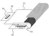
図8は、従来のフレキシブルディスプレイ50を示す構成図である。図8において、フレキシブルディスプレイ50は、フレキシブルな基板上に形成されたディスプレイパネル51と、ディスプレイパネル51の額縁部分に、それぞれ水平方向および垂直方向に取り付けられた2個のTCP52とから構成されている。また、2個のTCP52のそれぞれには、ディスプレイパネル51を駆動する駆動IC53が、互いに直交するように実装されている。
However, the prior art has the following problems.
FIG. 8 is a configuration diagram showing a conventional
ここで、このようなTCP52を有するフレキシブルディスプレイ50を、ディスプレイパネル51の水平方向または垂直方向に巻き取った場合には、ロール径を小さくすることができない。これは、TCP52に実装された駆動IC53が柔軟性を有していないので、フレキシブルディスプレイ50の巻き取りが阻害されるためである。
Here, when the
具体的には、図9に示されるように、ディスプレイパネル51の巻き取り方向に対して平行に配置された駆動IC53(例えば、長辺9.7mm×短辺1.6mm)の長辺により、フレキシブルディスプレイ50の巻き取りが阻害される。
Specifically, as shown in FIG. 9, by the long side of the drive IC 53 (for example, long side 9.7 mm × short side 1.6 mm) arranged in parallel to the winding direction of the
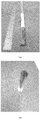
また、図10(a)、(b)に示されるように、このフレキシブルディスプレイ50のモックアップサンプルを、例えば直径が17mmの円筒に挿入すると、駆動IC53によってTCP52に応力がかかり、応力歪みが生じていることが分かる。そのため、TCP52が破損する恐れがある。なお、駆動IC53がディスプレイパネル51の基板上に直接実装される場合には、基板に応力がかかり、基板が破損する恐れがある。
Further, as shown in FIGS. 10A and 10B, when the mock-up sample of the
すなわち、従来のフレキシブルディスプレイでは、TCPや基板(TCP等)への駆動ICの配置が、フレキシブルディスプレイに配慮した設計となっていないので、柔軟性を有していない駆動ICによって、TCP等に応力歪みが生じるとともに、ロール径を小さくすることができないという問題がある。 That is, in the conventional flexible display, the arrangement of the driving IC on the TCP or the substrate (TCP or the like) is not designed in consideration of the flexible display. There are problems that distortion occurs and the roll diameter cannot be reduced.
この発明は、上記のような課題を解決するためになされたものであり、TCP等に応力歪みを生じることなく、小さなロール径を実現することができるフレキシブルディスプレイ、並びにフレキシブルディスプレイに適したTCPおよび駆動ICを得ることを目的とする。 The present invention has been made in order to solve the above-described problems. A flexible display capable of realizing a small roll diameter without causing stress distortion in TCP or the like, and a TCP suitable for a flexible display and An object is to obtain a driving IC.
この発明に係るフレキシブルディスプレイは、フレキシブルな基板上に形成されたディスプレイパネルと、ディスプレイパネルに対して水平方向および垂直方向に設けられ、ディスプレイパネルを駆動する複数の駆動ICとを備え、複数の駆動ICのすべてについて、長辺および短辺がそれぞれ同一の方向に配置され、かつ短辺がディスプレイパネルの巻き取り方向に対して平行に配置されているものである。 A flexible display according to the present invention includes a display panel formed on a flexible substrate, and a plurality of driving ICs that are provided in a horizontal direction and a vertical direction with respect to the display panel to drive the display panel. In all of the ICs, the long side and the short side are arranged in the same direction, and the short side is arranged in parallel to the winding direction of the display panel.
また、この発明に係るTCPは、フレキシブルな基板上に形成されたディスプレイパネルを備えたフレキシブルディスプレイに用いられるTCPであって、ディスプレイパネルを駆動する駆動ICが実装され、ディスプレイパネルとの接続部と駆動ICの短辺とが、互いに対向するものである。 Further, the TCP according to the present invention is a TCP used for a flexible display including a display panel formed on a flexible substrate, and a driving IC for driving the display panel is mounted, and a connection portion with the display panel The short sides of the driving IC are opposed to each other.
また、この発明に係る駆動ICは、フレキシブルディスプレイに用いられる駆動ICであって、短辺に入力端子が配置されているものである。 The drive IC according to the present invention is a drive IC used for a flexible display, and an input terminal is disposed on a short side.
この発明に係るフレキシブルディスプレイによれば、複数の駆動ICのすべてについて、長辺および短辺がそれぞれ同一の方向に配置され、かつ短辺がディスプレイパネルの巻き取り方向に対して平行に配置されている。
また、この発明に係るTCPによれば、ディスプレイパネルを駆動する駆動ICが実装され、ディスプレイパネルとの接続部と駆動ICの短辺とが、互いに対向する。
また、この発明に係る駆動ICによれば、短辺に入力端子が配置されている。
そのため、TCP等に応力歪みを生じることなく、小さなロール径を実現することができるフレキシブルディスプレイ、並びにフレキシブルディスプレイに適したTCPおよび駆動ICを得ることができる。
According to the flexible display of the present invention, for all of the plurality of drive ICs, the long side and the short side are arranged in the same direction, and the short side is arranged in parallel with the winding direction of the display panel. Yes.
Further, according to the TCP according to the present invention, the driving IC for driving the display panel is mounted, and the connection portion with the display panel and the short side of the driving IC face each other.
Further, according to the driving IC according to the present invention, the input terminal is arranged on the short side.
Therefore, it is possible to obtain a flexible display capable of realizing a small roll diameter without causing stress distortion in TCP or the like, and a TCP and a driving IC suitable for the flexible display.
以下、この発明に係るフレキシブルディスプレイ、並びにTCPおよび駆動ICの好適な実施の形態につき図面を用いて説明するが、各図において同一、または相当する部分については、同一符号を付して説明する。 Hereinafter, preferred embodiments of a flexible display, a TCP, and a driving IC according to the present invention will be described with reference to the drawings. In the drawings, the same or corresponding parts will be described with the same reference numerals.
なお、以下の各実施の形態において、TCPは、COF(Chip on FilmまたはChip on Flexible)およびTAB(Tape Automated Bonding)を含むものとする。 In each of the following embodiments, TCP includes COF (Chip on Film or Chip on Flexible) and TAB (Tape Automated Bonding).
実施の形態1.
図1は、この発明の実施の形態1に係るフレキシブルディスプレイ10を示す構成図である。図1において、フレキシブルディスプレイ10は、フレキシブルな基板上に形成されたディスプレイパネル11と、ディスプレイパネル11の額縁部分に、それぞれ水平方向および垂直方向に取り付けられた2個のTCP12とから構成されている。
FIG. 1 is a block diagram showing a
また、2個のTCP12のそれぞれには、ディスプレイパネル11を駆動する駆動IC13が実装されている。ここで、2個の駆動IC13は、長辺および短辺がそれぞれ同一の方向に配置され、かつ短辺がディスプレイパネル11の巻き取り方向(図の上下方向)に対して平行に配置されている。
Each of the two
そのため、このようなTCP12を有するフレキシブルディスプレイ10を、ディスプレイパネル11の巻き取り方向に巻き取った場合には、駆動IC13の長辺による巻き取りの阻害が生じないので、ロール径を小さくすることができる。なお、駆動IC13がディスプレイパネル11の基板上に直接実装される場合にも、同様のことがいえる。
Therefore, when the
具体的には、図2(a)、(b)に示されるように、このフレキシブルディスプレイ10のモックアップサンプルを、例えば直径が8mmの円筒に挿入した場合であっても、駆動IC13によってTCP12に応力がかかることはなく、応力歪みは生じない。すなわち、フレキシブルディスプレイ10が円滑に巻かれていることが分かる。
Specifically, as shown in FIGS. 2A and 2B, even if the mock-up sample of the
続いて、この発明の実施の形態1に係るTCP12における駆動IC13の配置について詳細に説明する。なお、ここで説明するTCP12は、ディスプレイパネル11の巻き取り方向に対して平行なパネル接続端子(接続部)により、ディスプレイパネル11に取り付けられるTCP12である。
Next, the arrangement of the
図3は、この発明の実施の形態1に係るフレキシブルディスプレイ10のTCP12の構成を、従来のTCPの構成と比較して示す説明図である。図3(a)は、従来のTCPの構成を示し、図3(b)は、この発明の実施の形態1に係るフレキシブルディスプレイ10のTCP12の構成を示している。
FIG. 3 is an explanatory diagram showing the configuration of the TCP 12 of the
図3(a)において、従来のTCPでは、ディスプレイパネルとの接続部であるパネル接続端子と駆動ICの長辺とが、互いに対向する配置となっている。これに対して、図3(b)において、この発明の実施の形態1に係るTCP12では、パネル接続端子と駆動IC13の短辺とが、互いに対向する配置となっている。
In FIG. 3A, in the conventional TCP, a panel connection terminal which is a connection portion with the display panel and a long side of the drive IC are arranged to face each other. On the other hand, in FIG. 3B, in the TCP 12 according to the first embodiment of the present invention, the panel connection terminal and the short side of the
ここで、図1に示した構成を、TCP12を用いて実現するには、上述したように、ディスプレイパネル11との接続部であるパネル接続端子と駆動IC13の短辺とを、互いに対向する配置とする必要がある。そこで、図3(b)に示したTCP12を用いることにより、図1に示した構成を、容易に実現することができる。
Here, in order to realize the configuration shown in FIG. 1 using the TCP 12, as described above, the panel connection terminal which is the connection portion with the
以上のように、実施の形態1によれば、フレキシブルディスプレイにおいて、複数の駆動ICのすべてについて、長辺および短辺がそれぞれ同一の方向に配置され、かつ短辺がディスプレイパネルの巻き取り方向に対して平行に配置されている。
そのため、TCP等に応力歪みを生じることなく、小さなロール径を実現することができるフレキシブルディスプレイを得ることができる。
As described above, according to the first embodiment, in the flexible display, the long side and the short side are arranged in the same direction for all of the plurality of drive ICs, and the short side is in the winding direction of the display panel. They are arranged in parallel.
Therefore, it is possible to obtain a flexible display capable of realizing a small roll diameter without causing stress distortion in TCP or the like.
また、実施の形態1によれば、TCPにおいて、ディスプレイパネルを駆動する駆動ICが実装され、ディスプレイパネルとの接続部と駆動ICの短辺とが、互いに対向する。
そのため、小さなロール径を実現することができるフレキシブルディスプレイを容易に実現することができる。
Further, according to the first embodiment, in the TCP, the driving IC for driving the display panel is mounted, and the connection portion with the display panel and the short side of the driving IC face each other.
Therefore, a flexible display capable of realizing a small roll diameter can be easily realized.
実施の形態2.
上記実施の形態1では、図1に示したように、2個の駆動IC13について、長辺および短辺がそれぞれ同一の方向に配置され、かつ短辺がディスプレイパネル11の巻き取り方向に対して平行に配置されたフレキシブルディスプレイ10を例に挙げて説明した。
Embodiment 2. FIG.
In the first embodiment, as shown in FIG. 1, the long sides and the short sides of the two
以下、図4を参照しながら、この発明の実施の形態1に係るフレキシブルディスプレイ10の課題について説明する。図4(a)は、この発明の実施の形態1に係るフレキシブルディスプレイ10の駆動IC13の構成を示し、図4(b)は、この発明の実施の形態1に係るフレキシブルディスプレイ10のTCP12の構成を、配線とともに示している。
Hereinafter, the problem of the
図4(a)に示されるように、実施の形態1の駆動IC13では、両側の長辺にそれぞれ入力端子および出力端子が配置されている。このような駆動IC13を、図1に示したフレキシブルディスプレイ10に適用すると、図4(b)に示されるように、駆動IC13の向きを変えたことにより、駆動IC13からパネル接続端子までの配線を迂回させる必要が生じる。
As shown in FIG. 4A, in the driving
ここで、配線を迂回させた場合には、配線長が長くなるので、インピーダンスが高くなるとともに、ノイズの影響を受けやすくなるという問題がある。また、配線長の差によって生じるインピーダンスの不整合により、信号の遅延や出力電圧レベルのずれといった問題を生じる恐れがある。 Here, when the wiring is detoured, since the wiring length becomes long, there is a problem that the impedance becomes high and it is easily affected by noise. Further, impedance mismatch caused by the difference in wiring length may cause problems such as signal delay and output voltage level deviation.
そこで、この発明の実施の形態2では、入力端子の数が、出力端子の数よりも少ないことに鑑みて、短辺がディスプレイパネル11と対向する駆動IC13において、上記のような課題を解決することができるフレキシブルディスプレイ10を提案する。
Therefore, in the second embodiment of the present invention, in view of the fact that the number of input terminals is smaller than the number of output terminals, the above-described problems are solved in the
図5は、この発明の実施の形態2に係るフレキシブルディスプレイ10の駆動IC13およびTCP12の構成を示す説明図である。図5(a)は、この発明の実施の形態2に係るフレキシブルディスプレイ10の駆動IC13の構成を示し、図5(b)は、この発明の実施の形態2に係るフレキシブルディスプレイ10のTCP12の構成を、配線とともに示している。
FIG. 5 is an explanatory diagram showing configurations of the
図5(a)に示されるように、この発明の実施の形態2に係る駆動IC13では、ディスプレイパネル11とは反対側の短辺に入力端子が配置され、長辺に出力端子が配置されている。
As shown in FIG. 5A, in the driving
このような駆動IC13を、図1に示したフレキシブルディスプレイ10に適用すると、図5(b)に示されるように、駆動IC13の向きを変えた場合であっても、迂回させることなく駆動IC13からパネル接続端子までの配線を形成することができる。
When such a driving
以上のように、実施の形態2によれば、駆動ICにおいて、短辺に入力端子が配置されている。
そのため、ディスプレイパネルとの接続部であるパネル接続端子と駆動ICの短辺とが、互いに対向するフレキシブルディスプレイの配置を、容易に実現することができる。
As described above, according to the second embodiment, the input terminal is arranged on the short side in the drive IC.
Therefore, it is possible to easily realize the arrangement of the flexible display in which the panel connection terminal which is a connection portion with the display panel and the short side of the drive IC face each other.
また、実施の形態2によれば、駆動ICの両側の長辺を出力端子とすることができるので、出力本数の増加に適している。また、駆動ICからパネル接続端子までの斜め配線を、容易に実現することができる。 Further, according to the second embodiment, the long sides on both sides of the driving IC can be used as output terminals, which is suitable for increasing the number of outputs. Further, oblique wiring from the drive IC to the panel connection terminal can be easily realized.
なお、この発明の実施の形態2に係る駆動IC13を用いることにより、図6に示されるような、TCP12を用いたフレキシブルディスプレイ10とともに、図7に示されるような、チップオンパネル(Chip on Panel)方式のフレキシブルディスプレイ10を実現することができる。図6、図7の何れも、図の上下方向を巻き取り方向として、フレキシブルディスプレイを実現している。
By using the
10 フレキシブルディスプレイ、11 ディスプレイパネル、12 TCP、13 駆動IC。 10 Flexible display, 11 Display panel, 12 TCP, 13 Drive IC.
Claims (5)
前記ディスプレイパネルに対して水平方向および垂直方向に設けられ、前記ディスプレイパネルを駆動する複数の駆動ICと、を備え、
前記複数の駆動ICのすべてについて、長辺および短辺がそれぞれ同一の方向に配置され、かつ短辺が前記ディスプレイパネルの巻き取り方向に対して平行に配置されている
フレキシブルディスプレイ。 A display panel formed on a flexible substrate;
A plurality of drive ICs that are provided in a horizontal direction and a vertical direction with respect to the display panel and drive the display panel;
A flexible display in which the long side and the short side are arranged in the same direction and the short side is arranged in parallel to the winding direction of the display panel for all of the plurality of drive ICs.
前記巻き取り方向に対して平行な接続部により、前記ディスプレイパネルに取り付けられるテープキャリアパッケージにおいて、前記接続部と実装された前記駆動ICの短辺とが、互いに対向する
請求項1に記載のフレキシブルディスプレイ。 The drive IC is mounted, and further comprises a plurality of tape carrier packages attached to the frame portion of the display panel in the horizontal direction and the vertical direction, respectively.
2. The flexible device according to claim 1, wherein, in the tape carrier package attached to the display panel, the connection portion and the short side of the mounted drive IC are opposed to each other by the connection portion parallel to the winding direction. display.
請求項1または請求項2に記載のフレキシブルディスプレイ。 3. The flexible display according to claim 1, wherein an input terminal is disposed on a short side opposite to the display panel in the driving IC facing the display panel with a short side.
前記ディスプレイパネルを駆動する駆動ICが実装され、
前記ディスプレイパネルとの接続部と前記駆動ICの短辺とが、互いに対向する
テープキャリアパッケージ。 A tape carrier package used for a flexible display including a display panel formed on a flexible substrate,
A driving IC for driving the display panel is mounted,
A tape carrier package in which a connection portion with the display panel and a short side of the drive IC are opposed to each other.
短辺に入力端子が配置されている
駆動IC。 A driving IC used for a flexible display,
A drive IC with input terminals on the short side.
Priority Applications (1)
| Application Number | Priority Date | Filing Date | Title |
|---|---|---|---|
| JP2012280817A JP5992319B2 (en) | 2012-12-25 | 2012-12-25 | Flexible display, tape carrier package and drive IC |
Applications Claiming Priority (1)
| Application Number | Priority Date | Filing Date | Title |
|---|---|---|---|
| JP2012280817A JP5992319B2 (en) | 2012-12-25 | 2012-12-25 | Flexible display, tape carrier package and drive IC |
Publications (2)
| Publication Number | Publication Date |
|---|---|
| JP2014126578A true JP2014126578A (en) | 2014-07-07 |
| JP5992319B2 JP5992319B2 (en) | 2016-09-14 |
Family
ID=51406152
Family Applications (1)
| Application Number | Title | Priority Date | Filing Date |
|---|---|---|---|
| JP2012280817A Expired - Fee Related JP5992319B2 (en) | 2012-12-25 | 2012-12-25 | Flexible display, tape carrier package and drive IC |
Country Status (1)
| Country | Link |
|---|---|
| JP (1) | JP5992319B2 (en) |
Cited By (5)
| Publication number | Priority date | Publication date | Assignee | Title |
|---|---|---|---|---|
| CN105938685A (en) * | 2015-03-06 | 2016-09-14 | 三星显示有限公司 | Display apparatus |
| CN108877535A (en) * | 2018-07-27 | 2018-11-23 | 武汉天马微电子有限公司 | foldable display panel and display device |
| JP2019527842A (en) * | 2016-07-11 | 2019-10-03 | 京東方科技集團股▲ふん▼有限公司Boe Technology Group Co.,Ltd. | Chip-on-film, flexible display device including the chip-on-film, and manufacturing method thereof |
| JP2019537053A (en) * | 2016-12-30 | 2019-12-19 | 深▲セン▼市柔宇科技有限公司Shenzhen Royole Technologies Co.,Ltd. | Flexible display panel |
| CN112639929A (en) * | 2018-12-29 | 2021-04-09 | 深圳市柔宇科技股份有限公司 | Display device |
Citations (9)
| Publication number | Priority date | Publication date | Assignee | Title |
|---|---|---|---|---|
| JPH06194680A (en) * | 1992-12-24 | 1994-07-15 | Casio Comput Co Ltd | Liquid crystal substrate |
| JPH11272205A (en) * | 1998-03-19 | 1999-10-08 | Toshiba Corp | Display device |
| JP2000132122A (en) * | 1998-10-28 | 2000-05-12 | Fuji Photo Film Co Ltd | Scroll-type display capable of continuous display |
| JP2002236457A (en) * | 1995-04-20 | 2002-08-23 | Canon Inc | Display device |
| JP2005517293A (en) * | 2002-02-06 | 2005-06-09 | シルバーブルック リサーチ ピーティワイ リミテッド | Compact display assembly |
| JP2005338179A (en) * | 2004-05-24 | 2005-12-08 | Sharp Corp | Display apparatus |
| WO2008013013A1 (en) * | 2006-07-27 | 2008-01-31 | Sharp Kabushiki Kaisha | Display device |
| JP2009085994A (en) * | 2007-09-27 | 2009-04-23 | Canon Inc | Picture display device |
| JP2011034066A (en) * | 2009-07-07 | 2011-02-17 | Semiconductor Energy Lab Co Ltd | Display |
-
2012
- 2012-12-25 JP JP2012280817A patent/JP5992319B2/en not_active Expired - Fee Related
Patent Citations (9)
| Publication number | Priority date | Publication date | Assignee | Title |
|---|---|---|---|---|
| JPH06194680A (en) * | 1992-12-24 | 1994-07-15 | Casio Comput Co Ltd | Liquid crystal substrate |
| JP2002236457A (en) * | 1995-04-20 | 2002-08-23 | Canon Inc | Display device |
| JPH11272205A (en) * | 1998-03-19 | 1999-10-08 | Toshiba Corp | Display device |
| JP2000132122A (en) * | 1998-10-28 | 2000-05-12 | Fuji Photo Film Co Ltd | Scroll-type display capable of continuous display |
| JP2005517293A (en) * | 2002-02-06 | 2005-06-09 | シルバーブルック リサーチ ピーティワイ リミテッド | Compact display assembly |
| JP2005338179A (en) * | 2004-05-24 | 2005-12-08 | Sharp Corp | Display apparatus |
| WO2008013013A1 (en) * | 2006-07-27 | 2008-01-31 | Sharp Kabushiki Kaisha | Display device |
| JP2009085994A (en) * | 2007-09-27 | 2009-04-23 | Canon Inc | Picture display device |
| JP2011034066A (en) * | 2009-07-07 | 2011-02-17 | Semiconductor Energy Lab Co Ltd | Display |
Cited By (6)
| Publication number | Priority date | Publication date | Assignee | Title |
|---|---|---|---|---|
| CN105938685A (en) * | 2015-03-06 | 2016-09-14 | 三星显示有限公司 | Display apparatus |
| CN105938685B (en) * | 2015-03-06 | 2020-06-05 | 三星显示有限公司 | Display device |
| JP2019527842A (en) * | 2016-07-11 | 2019-10-03 | 京東方科技集團股▲ふん▼有限公司Boe Technology Group Co.,Ltd. | Chip-on-film, flexible display device including the chip-on-film, and manufacturing method thereof |
| JP2019537053A (en) * | 2016-12-30 | 2019-12-19 | 深▲セン▼市柔宇科技有限公司Shenzhen Royole Technologies Co.,Ltd. | Flexible display panel |
| CN108877535A (en) * | 2018-07-27 | 2018-11-23 | 武汉天马微电子有限公司 | foldable display panel and display device |
| CN112639929A (en) * | 2018-12-29 | 2021-04-09 | 深圳市柔宇科技股份有限公司 | Display device |
Also Published As
| Publication number | Publication date |
|---|---|
| JP5992319B2 (en) | 2016-09-14 |
Similar Documents
| Publication | Publication Date | Title |
|---|---|---|
| JP5992319B2 (en) | Flexible display, tape carrier package and drive IC | |
| JP5940679B2 (en) | Drive module, display device, and multi-display device | |
| US10198028B2 (en) | Display panel, display panel assembly and method of manufacturing the same, and display device | |
| JP5315747B2 (en) | Display device | |
| US20170269420A1 (en) | Structure of chip on soft panel and liquid crystal display panel equipped with chip on soft panel | |
| JP2016099463A (en) | Liquid crystal display device | |
| JP2014215464A (en) | Display device | |
| TWI428607B (en) | Probe card | |
| US10790312B2 (en) | Display panel and display device | |
| TWI457671B (en) | Glass substrate of a flat panel display and integrated circuit chip for display | |
| JP5512589B2 (en) | Driver integrated circuit chip power supply connection structure | |
| JP2010204535A (en) | Liquid crystal display device | |
| CN102253513A (en) | Tape-coiling substrate of COF (chip on film) structure of liquid crystal display (LCD) panel as well as LCD panel | |
| JP2005159365A (en) | Semiconductor chip, chip-mounted tape carrier package, and liquid crystal display device including tape carrier package | |
| JP2009164560A (en) | Mounting structure, electrooptical device, and electronic apparatus | |
| WO2020213282A1 (en) | Display device, flexible wiring substrate, and method for manufacturing display device | |
| JP2022160815A (en) | Display device | |
| JP2006309184A (en) | Electrooptical apparatus, method for manufacturing the same, packaging structure, and electronic equipment | |
| JP2011186076A (en) | Display panel | |
| WO2021134836A1 (en) | Display device | |
| JP2007256724A (en) | Electro-optical device, mounting structure, method of manufacturing electro-optical device, and electronic equipment | |
| JP2006269583A (en) | Electrooptic device, manufacturing method thereof, mount structure, and electronic equipment | |
| JP2004184884A (en) | Display device | |
| KR102167135B1 (en) | Chip on film package | |
| CN203643707U (en) | LCD module and LCD device |
Legal Events
| Date | Code | Title | Description |
|---|---|---|---|
| A621 | Written request for application examination |
Free format text: JAPANESE INTERMEDIATE CODE: A621 Effective date: 20150409 |
|
| A977 | Report on retrieval |
Free format text: JAPANESE INTERMEDIATE CODE: A971007 Effective date: 20160224 |
|
| A131 | Notification of reasons for refusal |
Free format text: JAPANESE INTERMEDIATE CODE: A131 Effective date: 20160301 |
|
| A601 | Written request for extension of time |
Free format text: JAPANESE INTERMEDIATE CODE: A601 Effective date: 20160601 |
|
| RD02 | Notification of acceptance of power of attorney |
Free format text: JAPANESE INTERMEDIATE CODE: A7422 Effective date: 20160704 |
|
| A521 | Request for written amendment filed |
Free format text: JAPANESE INTERMEDIATE CODE: A523 Effective date: 20160728 |
|
| TRDD | Decision of grant or rejection written | ||
| A01 | Written decision to grant a patent or to grant a registration (utility model) |
Free format text: JAPANESE INTERMEDIATE CODE: A01 Effective date: 20160816 |
|
| A61 | First payment of annual fees (during grant procedure) |
Free format text: JAPANESE INTERMEDIATE CODE: A61 Effective date: 20160817 |
|
| R150 | Certificate of patent or registration of utility model |
Ref document number: 5992319 Country of ref document: JP Free format text: JAPANESE INTERMEDIATE CODE: R150 |
|
| R250 | Receipt of annual fees |
Free format text: JAPANESE INTERMEDIATE CODE: R250 |
|
| R250 | Receipt of annual fees |
Free format text: JAPANESE INTERMEDIATE CODE: R250 |
|
| R250 | Receipt of annual fees |
Free format text: JAPANESE INTERMEDIATE CODE: R250 |
|
| LAPS | Cancellation because of no payment of annual fees |