JP2014112533A - Ventilation member - Google Patents
Ventilation member Download PDFInfo
- Publication number
- JP2014112533A JP2014112533A JP2013219540A JP2013219540A JP2014112533A JP 2014112533 A JP2014112533 A JP 2014112533A JP 2013219540 A JP2013219540 A JP 2013219540A JP 2013219540 A JP2013219540 A JP 2013219540A JP 2014112533 A JP2014112533 A JP 2014112533A
- Authority
- JP
- Japan
- Prior art keywords
- ventilation
- opening
- water
- inner member
- attached
- Prior art date
- Legal status (The legal status is an assumption and is not a legal conclusion. Google has not performed a legal analysis and makes no representation as to the accuracy of the status listed.)
- Pending
Links
Images


Classifications
-
- F—MECHANICAL ENGINEERING; LIGHTING; HEATING; WEAPONS; BLASTING
- F21—LIGHTING
- F21V—FUNCTIONAL FEATURES OR DETAILS OF LIGHTING DEVICES OR SYSTEMS THEREOF; STRUCTURAL COMBINATIONS OF LIGHTING DEVICES WITH OTHER ARTICLES, NOT OTHERWISE PROVIDED FOR
- F21V31/00—Gas-tight or water-tight arrangements
- F21V31/03—Gas-tight or water-tight arrangements with provision for venting
-
- F—MECHANICAL ENGINEERING; LIGHTING; HEATING; WEAPONS; BLASTING
- F24—HEATING; RANGES; VENTILATING
- F24F—AIR-CONDITIONING; AIR-HUMIDIFICATION; VENTILATION; USE OF AIR CURRENTS FOR SCREENING
- F24F7/00—Ventilation
- F24F7/04—Ventilation with ducting systems, e.g. by double walls; with natural circulation
-
- F—MECHANICAL ENGINEERING; LIGHTING; HEATING; WEAPONS; BLASTING
- F16—ENGINEERING ELEMENTS AND UNITS; GENERAL MEASURES FOR PRODUCING AND MAINTAINING EFFECTIVE FUNCTIONING OF MACHINES OR INSTALLATIONS; THERMAL INSULATION IN GENERAL
- F16L—PIPES; JOINTS OR FITTINGS FOR PIPES; SUPPORTS FOR PIPES, CABLES OR PROTECTIVE TUBING; MEANS FOR THERMAL INSULATION IN GENERAL
- F16L21/00—Joints with sleeve or socket
-
- F—MECHANICAL ENGINEERING; LIGHTING; HEATING; WEAPONS; BLASTING
- F21—LIGHTING
- F21S—NON-PORTABLE LIGHTING DEVICES; SYSTEMS THEREOF; VEHICLE LIGHTING DEVICES SPECIALLY ADAPTED FOR VEHICLE EXTERIORS
- F21S45/00—Arrangements within vehicle lighting devices specially adapted for vehicle exteriors, for purposes other than emission or distribution of light
- F21S45/30—Ventilation or drainage of lighting devices
-
- H—ELECTRICITY
- H05—ELECTRIC TECHNIQUES NOT OTHERWISE PROVIDED FOR
- H05K—PRINTED CIRCUITS; CASINGS OR CONSTRUCTIONAL DETAILS OF ELECTRIC APPARATUS; MANUFACTURE OF ASSEMBLAGES OF ELECTRICAL COMPONENTS
- H05K5/00—Casings, cabinets or drawers for electric apparatus
- H05K5/02—Details
- H05K5/0213—Venting apertures; Constructional details thereof
- H05K5/0216—Venting plugs comprising semi-permeable membranes
-
- F—MECHANICAL ENGINEERING; LIGHTING; HEATING; WEAPONS; BLASTING
- F24—HEATING; RANGES; VENTILATING
- F24F—AIR-CONDITIONING; AIR-HUMIDIFICATION; VENTILATION; USE OF AIR CURRENTS FOR SCREENING
- F24F7/00—Ventilation
- F24F2007/0025—Ventilation using vent ports in a wall
Landscapes
- Engineering & Computer Science (AREA)
- General Engineering & Computer Science (AREA)
- Mechanical Engineering (AREA)
- Microelectronics & Electronic Packaging (AREA)
- Chemical & Material Sciences (AREA)
- Combustion & Propulsion (AREA)
- Arrangement Of Elements, Cooling, Sealing, Or The Like Of Lighting Devices (AREA)
- Casings For Electric Apparatus (AREA)
- Non-Portable Lighting Devices Or Systems Thereof (AREA)
- Self-Closing Valves And Venting Or Aerating Valves (AREA)
Abstract
Description
本発明は、筐体の開口に取り付けられる通気部材に関する。 The present invention relates to a ventilation member attached to an opening of a housing.
従来、例えば自動車用ランプやECU(Electrical Control Unit)などの自動車電装部品、OA(オフィスオートメーション)機器、家電製品、医療機器などでは、電子部品や制御基板などを収容する筐体に、温度変化による筐体内の圧力変動を緩和したり筐体内を換気したりする目的で開口が設けられ、この開口に通気部材が取り付けられることが行われている。この通気部材は、筐体の内外での通気を確保しつつ筐体内への塵や水などの異物の侵入を防ぐものである。 Conventionally, for example, automotive electrical components such as automotive lamps and ECUs (Electrical Control Units), OA (office automation) devices, home appliances, medical devices, etc., a housing that accommodates electronic components, control boards, etc. is subject to temperature changes. An opening is provided for the purpose of alleviating pressure fluctuations in the casing or ventilating the casing, and a ventilation member is attached to the opening. This ventilation member prevents intrusion of foreign matters such as dust and water into the casing while ensuring ventilation inside and outside the casing.
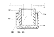
例えば、特許文献1には、図6に示すような通気部材100が開示されている。この通気部材100は、有底筒状のカバー部品101と、ゴム製の筒状体102と、防水通気膜103とで構成されている。筒状体102はカバー部品101よりも若干小径であり、この筒状体102の一方の開口を塞ぐように防水通気膜103が配置される。筒状体102を防水通気膜103側からカバー部品101の内側に嵌め込むことにより、カバー部品101の内周面と筒状体102の外周面との間、及びカバー部品101の底面と防水通気膜103との間に通気経路104が形成される。そして、筐体150に形成された開口部150aを筒状体102に挿入することにより、通気部材100を筐体150に取り付けることができる。
For example,
ところで、例えば自動車電装部品では、自動車が水によって洗浄されることがある。このような場合、通気部材100には水の強い圧力が加わり、通気経路104に水が侵入することがある。通気経路104に水が侵入して空気が通過できない事態に至ると、防水通気膜103が存在しても筐体150の内外の圧力差により水が内部空間に吸い込まれるおそれが生じる。
By the way, in an automobile electrical component, for example, the automobile may be washed with water. In such a case, a strong pressure of water is applied to the
本発明は、このような事情に鑑み、筐体の内部への水の侵入の防止により適した通気部材を提供することを目的とする。 In view of such circumstances, an object of the present invention is to provide a ventilation member that is more suitable for preventing water from entering the inside of a housing.
すなわち、本発明は、
筐体の開口部に取り付け可能な通気部材であって、
前記開口部に装着され、前記筐体の内部空間と外部空間との間の通気経路の一部として開口に防水通気膜が取り付けられていない貫通孔を有する筒状の内側部材と、
前記内側部材の外周部に装着され、前記貫通孔の開口を覆う有底筒状の外側部材とを備え、
前記内側部材及び前記外側部材は、水との接触角が80度以上である材料により形成されている、通気部材を提供する。
That is, the present invention
A ventilation member attachable to the opening of the housing,
A cylindrical inner member having a through-hole attached to the opening and having a waterproof breathable membrane attached to the opening as part of a ventilation path between the internal space and the external space of the housing;
A bottomed cylindrical outer member that is attached to the outer periphery of the inner member and covers the opening of the through hole;
The inner member and the outer member provide a ventilation member formed of a material having a contact angle with water of 80 degrees or more.
本発明による通気部材では、内側部材及び外側部材が水との接触角が80度以上である材料により形成されているため、通気経路に水が侵入しにくく筐体の内部への水の侵入の確実な防止に適している。また、本発明の通気部材によれば、通気部材と筐体との間に僅かな隙間が存在したとしても、筐体の内部への水の侵入を防止できる。さらに、本発明の通気部材は、防水通気膜を必要としないため、簡素な構造による防水と通気との両立にも適している。したがって、本発明は廉価で特性に優れた通気部材の提供にも適している。 In the ventilation member according to the present invention, since the inner member and the outer member are made of a material having a contact angle with water of 80 degrees or more, it is difficult for water to enter the ventilation path. Suitable for reliable prevention. Further, according to the ventilation member of the present invention, even if a slight gap exists between the ventilation member and the housing, water can be prevented from entering the inside of the housing. Furthermore, since the ventilation member of the present invention does not require a waterproof ventilation membrane, it is suitable for both waterproofing and ventilation with a simple structure. Therefore, the present invention is also suitable for providing a ventilation member that is inexpensive and has excellent characteristics.
以下、添付の図面を参照しつつ本発明の実施形態について説明する。なお、以下の説明は本発明の一例に関するものであり、本発明はこれらによって限定されるものではない。 Hereinafter, embodiments of the present invention will be described with reference to the accompanying drawings. The following description relates to an example of the present invention, and the present invention is not limited to these.
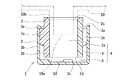
本発明の実施形態に係る通気部材1は、図1及び図2に示すように、筐体50の開口部50aに取り付けられるものである。開口部50aは、筐体50の内部空間と外部空間とを連通する貫通孔であって、筐体50の外側表面に円筒状に突出した首部50bに設けられている。通気部材1は、貫通孔2aを有する筒状の内側部材2と、内側部材2の外周部に装着され貫通孔2aの開口を覆う有底筒状の外側部材3と、を備えている。貫通孔2aは、内側部材2が首部50bに装着された状態で、筐体50の内部空間と外部空間との間の通気経路4の一部となる。貫通孔2aの開口の防水通気膜とその取付工程が省略されていることにより廉価な通気部材1を提供することが可能となる。内側部材2及び外側部材3は、水との接触角が80度以上である、疎水性の材料により形成されている。このため、通気経路4への水の侵入が防止される。ここで、水との接触角とは、表面に水が接触する部位から水の曲面に接線を引いたとき、この接線と表面とのなす角度であって、表面のぬれ性を表す指標である。例えば、接触角が小さいと表面がぬれやすく(親水性があり)、接触角が大きいと表面がぬれにくい(疎水性がある)。接触角は、日本工業規格(JIS) R3257(基板ガラス表面のぬれ性試験方法)に準拠する方法によって測定できる。
The
内側部材2は、表面と水との接触角が80度以上、好ましくは90度以上である熱可塑性エラストマー製の筒状部材である。なお、内側部材2の表面は、撥液処理されていない。言い換えると、内側部材2の表面には、撥液膜が形成されていない。内側部材2は、その全体が水との接触角が80度以上である材料によって形成されている。内側部材2は、内周部に貫通孔2aを有する円筒状の筒部2bと、筒部2bの外周面の中央部分に周方向に等間隔に突出して形成された4つの突出部2eとを有している。突出部2eの外周部は、外側部材3の内周部に接触する表面を提供する。突出部2eを形成した部分の内側部材2の外径は、外側部材3の内径よりも僅かに大きくなっている。外側部材3を内側部材2に装着したときに、突出部2eが弾性変形することによって、外側部材3は内側部材2に固定される。
The
貫通孔2aは、首部50bに装着される第1開口部2cと、第1開口部2cと逆側に設けられているとともに従来とは異なり防水通気膜が取り付けられていない第2開口部2dと、を有している。内側部材2は、第1開口部2c側から首部50bの外周に装着され、貫通孔2aが筐体50の内部空間と連通している。内側部材2の貫通孔2aは、第2開口部2dと、内側部材2の外周部と外側部材3の内周部との間の連通経路8,9とを介して外部空間(外部雰囲気)に連通している。連通経路8は、内側部材2の第2開口部2dと、外側部材3の底部3cの内周部との間に形成された隙間である。連通経路9は、突出部2eが形成されていない内側部材2の外周部と、外側部材3の内周部との間に形成された隙間である。このように、通気部材1は、内側部材2と外側部材3との間に、通気経路4の一部となる連通経路8,9を有し、連通経路8,9が外部空間へと連通している。
The through
通気経路4は、内側部材2の貫通孔2aと、連通経路8,9とで構成されている。通気経路4は、防水通気膜により区分されていない連続した空間である。すなわち、貫通孔2aのみならず、連通経路8,9にも防水通気膜は配置されていない。通気経路4を通じての水の侵入の防止は、防水通気膜ではなく、内側部材2及び外側部材3の表面の疎水性により実現されている。水の侵入の防止は、通気経路4の少なくとも一部を狭小とすることにより確実に実現できる。通気部材1においては、貫通孔2aが連通経路8,9よりも狭小に設計されている。水の侵入の確実な防止のためには、外部雰囲気に面する開口部3aを小さくしておくとよい。
The ventilation path 4 includes a through
開口部3aは、内側部材2の外周部と外側部材3の内周部との間に形成された平面視リング状の隙間である。開口部3aは、連通経路9に連通するとともに、外部空間に向けて開口している。図5に拡大して示すように、開口部3aにおける内側部材2の外周部と外側部材3の内周部との間の距離dは、好ましくは1.75mm以下、特に好ましくは1.0mm以下である。なお、従来の通気部材100の開口部104a(図6参照)における筒状体102の外周部とカバー部品101の内周部との間の距離は、1.75mmを上回っていた。従来の通気部材100では、防水通気膜103により防水性が確保されていたためである。
The
外側部材3は、表面と水との接触角が80度以上、好ましくは90度以上であるPP(ポリプロピレン)製の有底筒状の部材である。なお、外側部材3の表面は、撥液処理されていない。言い換えると、外側部材3の表面には、撥液膜が形成されていない。外側部材3は、その全体が水との接触角が80度以上である材料によって形成されている。外側部材3は、内側部材2の外周部に装着される開口部3aを有する筒部3bと、開口部3aと逆側に設けられ内周部が内側部材2の第2開口部2dに対向する底部3cと、を有している。底部3cの内周側の周縁部には、3つの台部3dが周方向に等間隔で形成されている。また、開口部3aの内周側の周縁部には、3つの係合片3eが内側に突出して等間隔で形成されている。
The
外側部材3に内側部材2が嵌装されている状態では、突出部2eの外周面が外側部材3の内周面を圧接し、突出部2eの上面が係合片3eに係合している。さらに、外側部材3に内側部材2が嵌装されている状態では、内側部材2が外側部材3の底面まで挿入されたとしても、外側部材3の底面に形成された台部3dと内側部材2の第2開口部2dとが当接し、外側部材3の底部3cと内側部材2の第2開口部2dとの間に連通経路8が確保される。
In a state where the
内側部材2及び外側部材3を形成する材料は、上記の例示(熱可塑性エラストマー、PP)に限らず、水との接触角が80度以上である樹脂であればよい。また、内側部材2及び外側部材3は、水との接触角が80度以上であれば、同じ材料で構成されていてもよいし、異なる材料で構成されていてもよい。このような材料としては、成型性及び溶着の観点からPET(ポリエチレンテレフタレート)、PPS(ポリフェニレンスルフィド)、PBT(ポリブチレンテレフタレート)、PC(ポリカーボネート)、PP(ポリプロピレン)、PPE(ポリフェニレンエーテル)等の熱可塑性の樹脂を用いることが好ましい。
The material for forming the
ただし、本実施形態の通気部材1では、内側部材2及び外側部材3は、水との接触角が80度以上である疎水性の材料を選択し、この材料により形成する必要がある。本実施形態の通気部材1によれば、通気部材1と筐体50との間からの水の侵入も防止できる。
However, in the
以下、本発明を実施例によりさらに詳細に説明するが、本発明は以下の実施例に制限されるものではない。以下の実施例及び比較例では、図示した通気部材1と同様の構造を有する通気部材を作製した。
EXAMPLES Hereinafter, although an Example demonstrates this invention further in detail, this invention is not restrict | limited to a following example. In the following examples and comparative examples, a ventilation member having the same structure as the illustrated
最初に、内側部材2及び外側部材3の表面と水との接触角の測定方法を示す。
Initially, the measuring method of the contact angle of the surface of the
[接触角]
内側部材2及び外側部材3の表面と水との接触角(度)は、JIS R3257(基板ガラス表面のぬれ性試験方法)に準拠して、内側部材2及び外側部材3に使用されている樹脂と同じ樹脂のシート(縦92mm×横92mmとなる正方形のシート)を試験サンプルとして準備し、接触角測定装置(Contact Angle System OCA 30(DataPhysics Instruments GmbH製))を用いて測定した。
[Contact angle]
The contact angle (degree) between the surface of the
(実施例1)
内側部材2の外径が12.0mm、外側部材3の内径が15.5mm、すなわち、開口部3aにおける内側部材2の外周部と外側部材3の内周部との間の距離dが1.75mmとなる内側部材2及び外側部材3を作製した。内側部材2の材料としては、水Wとの接触角θ2が91度である熱可塑性エラストマー(JSR株式会社製、EXCELINK 1100B)を用いた(図4参照)。外側部材3の材料としては、水Wとの接触角θ1が96度であるPP(ポリプロピレン、サンアロマー株式会社製、PM854X)を用いた(図3参照)。通気部材1を図1のような筐体50に差しこみ、上方から水を連続して滴下する試験を実施した。筐体50の内部に水の侵入は認められなかった。
Example 1
The outer diameter of the
(比較例1)
表面と水との接触角が77度であるPA(ポリアミド、宇部興産株式会社製、UBEナイロン66)製の内側部材2と、表面と水との接触角が10度であるパラフィン(株式会社ジーシー製、PARAFFIN WAX)製の外側部材3とを用いたことを除いては、実施例1と同様にして試験を実施した。筐体50の内部には水が侵入した。
(Comparative Example 1)
The
(比較例2)
表面と水との接触角が77度であるPA(ポリアミド、宇部興産株式会社製、UBEナイロン66)製の内側部材2と、表面と水との接触角が60度であるフェノール樹脂(DIC株式会社製、フェノライト)製の外側部材3とを用いたことを除いては、実施例1と同様にして試験を実施した。筐体50の内部には水が侵入した。
(Comparative Example 2)
The
実施例1では、内側部材2の貫通孔2aの開口に防水通気膜が取り付けられていない。防水通気膜がなくても、内側部材2及び外側部材3を、水との接触角が80度以上である疎水性の材料により形成することによって、水の侵入を防止することができる。
In Example 1, the waterproof breathable membrane is not attached to the opening of the through
本発明に係る防水通気部材は、自動車電装部品の筐体のみならず、例えば、OA機器、家電製品、医療機器の筺体への使用にも適している。 The waterproof ventilation member according to the present invention is suitable not only for the housing of automobile electrical components, but also for use in, for example, OA equipment, home appliances, and medical equipment housings.
1 通気部材
2 内側部材
2a 貫通孔
2b 筒部
2c 第1開口部
2d 第2開口部
2e 突出部
3 外側部材
3a 開口部
3b 筒部
3c 底部
3d 台部
3e 係合片
4 通気経路
8,9 連通経路
50 筐体
50a 開口部
50b 首部
100 通気部材
101 カバー部品
102 筒状体
103 防水通気膜
104 通気経路
104a 開口部
150 筐体
150a 開口部
DESCRIPTION OF
Claims (6)
前記開口部に装着され、前記筐体の内部空間と外部空間との間の通気経路の一部として開口に防水通気膜が取り付けられていない貫通孔を有する筒状の内側部材と、
前記内側部材の外周部に装着され、前記貫通孔の開口を覆う有底筒状の外側部材とを備え、
前記内側部材及び前記外側部材は、水との接触角が80度以上である材料により形成されている、通気部材。 A ventilation member attachable to the opening of the housing,
A cylindrical inner member having a through-hole attached to the opening and having a waterproof breathable membrane attached to the opening as part of a ventilation path between the internal space and the external space of the housing;
A bottomed cylindrical outer member that is attached to the outer periphery of the inner member and covers the opening of the through hole;
The ventilation member, wherein the inner member and the outer member are made of a material having a contact angle with water of 80 degrees or more.
前記連通経路が前記外部空間へと連通する、請求項1に記載の通気部材。 Between the inner member and the outer member, there is a communication path that becomes a part of the ventilation path,
The ventilation member according to claim 1, wherein the communication path communicates with the external space.
Priority Applications (1)
| Application Number | Priority Date | Filing Date | Title |
|---|---|---|---|
| JP2013219540A JP2014112533A (en) | 2012-11-01 | 2013-10-22 | Ventilation member |
Applications Claiming Priority (3)
| Application Number | Priority Date | Filing Date | Title |
|---|---|---|---|
| JP2012242218 | 2012-11-01 | ||
| JP2012242218 | 2012-11-01 | ||
| JP2013219540A JP2014112533A (en) | 2012-11-01 | 2013-10-22 | Ventilation member |
Publications (1)
| Publication Number | Publication Date |
|---|---|
| JP2014112533A true JP2014112533A (en) | 2014-06-19 |
Family
ID=48688724
Family Applications (1)
| Application Number | Title | Priority Date | Filing Date |
|---|---|---|---|
| JP2013219540A Pending JP2014112533A (en) | 2012-11-01 | 2013-10-22 | Ventilation member |
Country Status (7)
| Country | Link |
|---|---|
| US (1) | US20150276244A1 (en) |
| EP (1) | EP2916067A4 (en) |
| JP (1) | JP2014112533A (en) |
| KR (1) | KR20150082215A (en) |
| CN (2) | CN203036605U (en) |
| IN (1) | IN2015DN02709A (en) |
| WO (1) | WO2014068902A1 (en) |
Cited By (1)
| Publication number | Priority date | Publication date | Assignee | Title |
|---|---|---|---|---|
| WO2019198809A1 (en) * | 2018-04-13 | 2019-10-17 | 株式会社W | Freshness-retaining bag and method for producing same |
Families Citing this family (4)
| Publication number | Priority date | Publication date | Assignee | Title |
|---|---|---|---|---|
| KR102021145B1 (en) * | 2017-01-25 | 2019-09-11 | 주식회사 아모그린텍 | Cap type vent |
| JP7446233B2 (en) | 2018-10-11 | 2024-03-08 | 日東電工株式会社 | ventilation casing |
| CN111316763B (en) | 2018-10-11 | 2023-03-07 | 日东电工株式会社 | Ventilation assembly and ventilation shell |
| CN114930993A (en) * | 2020-01-14 | 2022-08-19 | 日东电工株式会社 | Ventilation member |
Citations (1)
| Publication number | Priority date | Publication date | Assignee | Title |
|---|---|---|---|---|
| JP2001143524A (en) * | 1999-11-18 | 2001-05-25 | Nitto Denko Corp | Vent cap and outdoor lamp using the same, lamp for car and electric equipment part for car |
Family Cites Families (5)
| Publication number | Priority date | Publication date | Assignee | Title |
|---|---|---|---|---|
| US4237526A (en) * | 1978-05-19 | 1980-12-02 | Union Carbide Corporation | Battery operated device having a waterproof housing and gas discharge vent |
| JPS61122879A (en) | 1984-11-17 | 1986-06-10 | シルバー精工株式会社 | Score totalization apparatus of baseball |
| JPH0433171Y2 (en) * | 1985-06-19 | 1992-08-10 | ||
| US20120059466A1 (en) * | 2010-09-02 | 2012-03-08 | Chi-Chun Tsai | Intraocular lenses with interlenticular opacification resistance |
| KR101056026B1 (en) * | 2011-04-14 | 2011-08-10 | (주)상아프론테크 | Venting apparatus |
-
2012
- 2012-12-25 CN CN2012207235841U patent/CN203036605U/en not_active Expired - Lifetime
-
2013
- 2013-10-22 EP EP13850315.6A patent/EP2916067A4/en not_active Withdrawn
- 2013-10-22 IN IN2709DEN2015 patent/IN2015DN02709A/en unknown
- 2013-10-22 JP JP2013219540A patent/JP2014112533A/en active Pending
- 2013-10-22 KR KR1020157009814A patent/KR20150082215A/en not_active Application Discontinuation
- 2013-10-22 CN CN201380057245.1A patent/CN104781605A/en active Pending
- 2013-10-22 WO PCT/JP2013/006246 patent/WO2014068902A1/en active Application Filing
- 2013-10-22 US US14/434,008 patent/US20150276244A1/en not_active Abandoned
Patent Citations (1)
| Publication number | Priority date | Publication date | Assignee | Title |
|---|---|---|---|---|
| JP2001143524A (en) * | 1999-11-18 | 2001-05-25 | Nitto Denko Corp | Vent cap and outdoor lamp using the same, lamp for car and electric equipment part for car |
Cited By (1)
| Publication number | Priority date | Publication date | Assignee | Title |
|---|---|---|---|---|
| WO2019198809A1 (en) * | 2018-04-13 | 2019-10-17 | 株式会社W | Freshness-retaining bag and method for producing same |
Also Published As
| Publication number | Publication date |
|---|---|
| US20150276244A1 (en) | 2015-10-01 |
| IN2015DN02709A (en) | 2015-09-04 |
| EP2916067A1 (en) | 2015-09-09 |
| EP2916067A4 (en) | 2016-11-23 |
| CN203036605U (en) | 2013-07-03 |
| WO2014068902A1 (en) | 2014-05-08 |
| CN104781605A (en) | 2015-07-15 |
| KR20150082215A (en) | 2015-07-15 |
Similar Documents
| Publication | Publication Date | Title |
|---|---|---|
| WO2014068902A1 (en) | Ventilation member | |
| US8814993B2 (en) | Vent structure | |
| US9120059B2 (en) | Ventilation unit | |
| US9120060B2 (en) | Ventilation unit | |
| KR20010049300A (en) | Air-permeable cap and outdoor lamp, automobile lamp and automobile electrical component comprising same | |
| KR102418290B1 (en) | Absence of ventilation and inspection method | |
| JP2013114829A (en) | Ventilation member | |
| JP2014102970A (en) | Ventilation member | |
| JP6132615B2 (en) | Ventilation member | |
| KR20160040546A (en) | Ventilation structure and ventilation member | |
| JP2008055981A (en) | Electronic control device | |
| JP2005243829A (en) | Case | |
| WO2018139339A1 (en) | Cover member and wire harness | |
| KR101701469B1 (en) | ventilation cap for car | |
| JP5710359B2 (en) | Ventilation member | |
| KR20120055432A (en) | Apparatus for capping vent | |
| JP7075418B2 (en) | Housing kit and ventilation member | |
| JP2003258444A (en) | Case for electronic device | |
| JP6121210B2 (en) | Ventilation member | |
| JP7399893B2 (en) | Ventilation parts and ventilation structures | |
| KR102634104B1 (en) | vent parts | |
| WO2021117779A1 (en) | Ventilation component | |
| CN104220291A (en) | Indication apparatus | |
| KR101701473B1 (en) | ventilation cap for car | |
| KR102458252B1 (en) | Electronic control device |
Legal Events
| Date | Code | Title | Description |
|---|---|---|---|
| A621 | Written request for application examination |
Free format text: JAPANESE INTERMEDIATE CODE: A621 Effective date: 20160720 |
|
| A977 | Report on retrieval |
Free format text: JAPANESE INTERMEDIATE CODE: A971007 Effective date: 20170420 |
|
| A131 | Notification of reasons for refusal |
Free format text: JAPANESE INTERMEDIATE CODE: A131 Effective date: 20170509 |
|
| A02 | Decision of refusal |
Free format text: JAPANESE INTERMEDIATE CODE: A02 Effective date: 20171031 |