JP2014109150A - Column-beam joint structure - Google Patents

Column-beam joint structure Download PDF

Info

Publication number
JP2014109150A
JP2014109150A JP2012264642A JP2012264642A JP2014109150A JP 2014109150 A JP2014109150 A JP 2014109150A JP 2012264642 A JP2012264642 A JP 2012264642A JP 2012264642 A JP2012264642 A JP 2012264642A JP 2014109150 A JP2014109150 A JP 2014109150A
Authority
JP
Japan
Prior art keywords
column member
joining jig
core
jig
wooden
Prior art date
Legal status (The legal status is an assumption and is not a legal conclusion. Google has not performed a legal analysis and makes no representation as to the accuracy of the status listed.)
Granted
Application number
JP2012264642A
Other languages
Japanese (ja)
Other versions
JP6034164B2 (en
Inventor
Atsuchika Hanai
厚周 花井
Naoki Aso
直木 麻生
Current Assignee (The listed assignees may be inaccurate. Google has not performed a legal analysis and makes no representation or warranty as to the accuracy of the list.)
Takenaka Komuten Co Ltd
Original Assignee
Takenaka Komuten Co Ltd
Priority date (The priority date is an assumption and is not a legal conclusion. Google has not performed a legal analysis and makes no representation as to the accuracy of the date listed.)
Filing date
Publication date
Application filed by Takenaka Komuten Co Ltd filed Critical Takenaka Komuten Co Ltd
Priority to JP2012264642A priority Critical patent/JP6034164B2/en
Publication of JP2014109150A publication Critical patent/JP2014109150A/en
Application granted granted Critical
Publication of JP6034164B2 publication Critical patent/JP6034164B2/en
Active legal-status Critical Current
Anticipated expiration legal-status Critical

Links

Images

Abstract

PROBLEM TO BE SOLVED: To enhance fire resistance efficiency of a joint part between a wooden column member and a beam member.SOLUTION: A column-beam joint structure 10 includes: a lower column member 12 that serves as a wooden column member; a joint jig 50 that is fixed to an upper end surface of the lower column member 12; a concrete hardened body 80 (see Fig. 4) that serves as a cement-based hardened body for coating the joint jig 50; and a steel beam 30 that serves as a beam member joined to the lower column member 12 via the joint jig 50.

Description

本発明は、柱梁接合構造に関する。   The present invention relates to a column beam connection structure.

木質柱の仕口部内に設けられた金属金具に、木質梁の端部から突出した鉤状部を引っ掛けることにより、木質柱と木質梁とを接合する木質構造材の接合構造が知られている(例えば、特許文献1参照)。   A joining structure of a wooden structure material that joins a wooden column and a wooden beam by hooking a hook-shaped part protruding from the end of the wooden beam to a metal fitting provided in the joint of the wooden column is known. (For example, refer to Patent Document 1).

特許文献1に開示された技術では、金属金具が木質柱の仕口部内に設けられているため、火災時に金属金具が火炎に直接さらされないようになっている。   In the technique disclosed in Patent Literature 1, since the metal fitting is provided in the joint portion of the wooden pillar, the metal fitting is not directly exposed to the flame in the event of a fire.

特開平10−317496号公報Japanese Patent Application Laid-Open No. 10-317496

しかしながら、特許文献1に開示された技術では、金属金具を被覆する木質柱の仕口部が火災時に燃焼し易く、金属金具が熱劣化し易い。   However, in the technique disclosed in Patent Document 1, the joint portion of the wooden pillar covering the metal fitting is likely to burn during a fire, and the metal fitting is likely to be thermally deteriorated.

本発明は、上記の事実を考慮し、木質柱部材と梁部材との仕口部の耐火性能を向上させることを目的とする。   In view of the above facts, an object of the present invention is to improve the fire resistance of the joint portion between the wooden column member and the beam member.

請求項1に記載の柱梁接合構造は、上端に金属製の接合治具を有する木質柱部材と、前記接合治具に接合された梁部材と、前記接合治具を被覆するセメント系硬化体と、を備えている。   The beam-column joining structure according to claim 1 is a cement-based cured body that covers a wooden column member having a metal joining jig at an upper end, a beam member joined to the joining jig, and the joining jig. And.

請求項1に係る柱梁接合構造によれば、セメント系硬化体は木材と比較して燃焼し難く、かつ熱容量が大きい。このセメント系硬化体によって接合治具を被覆することにより、火災時における接合治具の温度上昇が抑制される。これにより、接合治具の熱劣化が抑制される。したがって、木質柱部材と梁部材との仕口部の耐火性能が向上する。   According to the column beam connection structure according to the first aspect, the cement-based hardened body is less likely to burn and has a larger heat capacity than wood. By covering the joining jig with this cement-based hardened body, the temperature rise of the joining jig during a fire is suppressed. Thereby, the thermal deterioration of a joining jig is suppressed. Therefore, the fire resistance performance of the joint portion between the wooden column member and the beam member is improved.

請求項2に記載の柱梁接合構造は、請求項1に記載の柱梁接合構造において、前記木質柱部材が、木製の心部と、前記心部の外側に配置された燃え止まり層と、前記燃え止まり層の外側に配置された木製の燃え代層と、を有し、前記接合治具が、前記心部に接合されている。   The beam-column joint structure according to claim 2 is the beam-column joint structure according to claim 1, wherein the wooden column member includes a wooden core part, and a flame stop layer disposed outside the core part. A wood burning allowance layer disposed outside the flame stop layer, and the joining jig is joined to the core.

請求項2に係る柱梁接合構造によれば、火災時には、木製の燃え代層が徐々に燃焼して断熱性を有する炭化層を形成する。これにより、心部への熱の侵入(熱伝達)が抑制される。さらに、燃え代層の内側に配置された燃え止まり層によって燃え代層の燃焼を停止(自然鎮火)させることができる。これにより、燃え止まり層の内側に配置された心部の燃焼が抑制される。したがって、木質柱部材の耐火性能が向上する。   According to the column beam connection structure according to claim 2, in the event of a fire, the wood burning allowance layer gradually burns to form a carbonized layer having heat insulation properties. Thereby, the penetration | invasion (heat transfer) of the heat | fever to a heart part is suppressed. Furthermore, the combustion of the burning allowance layer can be stopped (spontaneous extinguishing) by the dead end layer disposed inside the burning allowance layer. Thereby, the combustion of the core part arrange | positioned inside the flame-stopping layer is suppressed. Therefore, the fire resistance performance of the wooden column member is improved.

また、接合治具を木質柱部材の心部に接合したことにより、接合治具から木質柱部材の心部に軸力(鉛直荷重)を伝達することができる。   Further, since the joining jig is joined to the core of the wooden column member, axial force (vertical load) can be transmitted from the joining jig to the center of the wooden column member.

請求項3に記載の柱梁接合構造は、請求項2に記載の柱梁接合構造において、前記セメント系硬化体が、コンクリート硬化体であり、前記コンクリート硬化体には、前記心部内へ延びる固定部材が埋設されている。   The beam-column joint structure according to claim 3 is the beam-column joint structure according to claim 2, wherein the cement-based hardened body is a hardened concrete body, and the hardened concrete body is fixed to extend into the core. The member is embedded.

請求項3に係る柱梁接合構造によれば、セメント系硬化体が、コンクリート硬化体とされている。このコンクリート硬化体には、木質柱部材の心部内へ延びる固定部材が埋設されている。この固定部材によって、コンクリート硬化体が木質柱部材の心部に固定されている。これにより、固定部材の引張り力によって梁部材から木質柱部材へ曲げモーメントが伝達されるため、木質柱部材に対する梁部材の材軸方向の端部の固定度が上がる。したがって、常時及び地震時における梁部材の変形が抑制されるため、居住性及び耐震性能が向上する。   According to the beam-column joint structure according to claim 3, the cement-based hardened body is a concrete hardened body. A fixed member extending into the core of the wooden column member is embedded in the hardened concrete body. By this fixing member, the concrete hardened body is fixed to the core of the wooden column member. Thereby, since the bending moment is transmitted from the beam member to the wooden column member by the tensile force of the fixing member, the fixing degree of the end of the beam member in the material axis direction with respect to the wooden column member is increased. Therefore, since the deformation of the beam member at all times and during an earthquake is suppressed, the comfortability and the earthquake resistance are improved.

以上説明したように、本発明に係る柱梁接合構造によれば、木質柱部材と梁部材との仕口部の耐火性能を向上させることができる。   As described above, according to the column-beam joint structure according to the present invention, it is possible to improve the fire resistance performance of the joint portion between the wooden column member and the beam member.

本発明の一実施形態に係る柱梁接合構造が適用された下柱部材、上柱部材、及び鉄骨梁を示す分解斜視図である。It is a disassembled perspective view which shows the lower column member, the upper column member, and the steel beam to which the column beam joining structure which concerns on one Embodiment of this invention was applied. 図3の2−2線断面に相当する断面図である。FIG. 4 is a cross-sectional view corresponding to a cross section taken along line 2-2 of FIG. 3. 図2の3−3線断面に相当する断面図である。FIG. 3 is a cross-sectional view corresponding to a cross section taken along line 3-3 in FIG. 2. 本発明の一実施形態におけるコンクリート硬化体を示す図3に相当する断面図である。It is sectional drawing equivalent to FIG. 3 which shows the concrete hardening body in one Embodiment of this invention. 本発明の一実施形態に係る柱梁接合構造の変形例が適用された下柱部材、上柱部材、及び鉄骨梁を示す図4に相当する断面図である。It is sectional drawing equivalent to FIG. 4 which shows the lower column member, the upper column member, and the steel beam to which the modification of the column beam junction structure which concerns on one Embodiment of this invention was applied. 本発明の一実施形態における接合治具の変形例を示す斜視図である。It is a perspective view which shows the modification of the joining jig in one Embodiment of this invention. 本発明の一実施形態における接合治具の変形例を示す斜視図である。It is a perspective view which shows the modification of the joining jig in one Embodiment of this invention. 図7に示される下柱部材及び接合治具を示す縦断面図である。It is a longitudinal cross-sectional view which shows the lower column member and joining jig | tool shown by FIG. 本発明の一実施形態における接合治具の変形例を示す斜視図である。It is a perspective view which shows the modification of the joining jig in one Embodiment of this invention. 図9に示される下柱部材及び接合治具を示す縦断面図である。It is a longitudinal cross-sectional view which shows the lower pillar member and joining jig | tool shown by FIG. 本発明の一実施形態における接合治具の変形例を示す斜視図である。It is a perspective view which shows the modification of the joining jig in one Embodiment of this invention. 図11に示される下柱部材及び接合治具を示す縦断面図である。It is a longitudinal cross-sectional view which shows the lower pillar member and joining jig | tool shown by FIG.

以下、図を参照しながら、本発明の一実施形態に係る柱梁接合構造について説明する。   Hereinafter, a column beam connection structure according to an embodiment of the present invention will be described with reference to the drawings.

(柱梁接合構造の構成)
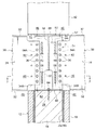
図1に示されるように、本実施形態に係る柱梁接合構造10は、木質柱部材としての下柱部材12と、下柱部材12の上端面に固定される接合治具50と、接合治具50を被覆するセメント系硬化体としてのコンクリート硬化体80(図4参照)と、接合治具50を介して下柱部材12と接合される梁部材としての鉄骨梁30とを備えている。
(Structure of column beam connection structure)
As shown in FIG. 1, a beam-column joining structure 10 according to the present embodiment includes a lower column member 12 as a wooden column member, a joining jig 50 fixed to the upper end surface of the lower column member 12, and a joining treatment. A hardened concrete body 80 (see FIG. 4) as a cemented hardened body covering the tool 50 and a steel beam 30 as a beam member joined to the lower column member 12 via the joining jig 50 are provided.

(下柱部材の構成)
下柱部材12には、耐火構造が適用されている。この下柱部材12は、断面矩形(本実施形態では略正方形)に形成されており、長期及び短期荷重(長期及び短期軸力)を支持する木製の心部(荷重支持部)14と、心部14を被覆(耐火被覆)する被覆部としての燃え止まり層16及び燃え代層18とを有している。心部14は、下柱部材12が負担する長期及び短期荷重(全荷重)を支持可能に構成されており、木材を板状や角柱状に加工した複数の木製単材を接着剤等で一体化させた集成材によって断面矩形に形成されている。
(Configuration of lower pillar member)
A fireproof structure is applied to the lower column member 12. The lower column member 12 is formed in a rectangular cross section (substantially square in the present embodiment), and includes a wooden core (load support section) 14 that supports long-term and short-term loads (long-term and short-term axial forces), and a core. It has the flame stop layer 16 and the burn allowance layer 18 as a coating part which coat | covers the part 14 (fireproof coating). The core portion 14 is configured to be capable of supporting long-term and short-term loads (total loads) borne by the lower column member 12, and a plurality of wooden single materials obtained by processing wood into a plate shape or a prismatic shape are integrated with an adhesive or the like. It is formed into a rectangular cross section by the laminated material.

心部14の外側(外周)には、燃え止まり層16が配置されている。燃え止まり層16は、火災時における燃え代層18の燃焼を停止(自然鎮火)させ、心部14の燃焼を抑制する層であり、心部14よりも熱容量が大きくなっている。この燃え止まり層16は、心部14の外周面に沿って交互に配列された複数のモルタル板(モルタルバー)20及び木板22を有し、心部14を囲んでいる。   On the outer side (outer periphery) of the core portion 14, a flame stop layer 16 is disposed. The non-burning layer 16 is a layer that stops the combustion of the burning allowance layer 18 at the time of a fire (spontaneous fire suppression) and suppresses the burning of the core part 14, and has a larger heat capacity than the core part 14. This flame stop layer 16 has a plurality of mortar plates (mortar bars) 20 and wood plates 22 arranged alternately along the outer peripheral surface of the core portion 14, and surrounds the core portion 14.

モルタル板20は木材よりも熱容量が大きく、このモルタル板20と木板22とを交互に配置することにより、燃え止まり層16の熱容量が全体として心部14よりも大きくなっている。なお、隣接するモルタル板20と木板22とは接触し、又は接着剤等で接着されており、相互に熱を伝達可能になっている。また、モルタル板20及び木板22は、心部14に接着剤等で接合されている。   The mortar board 20 has a larger heat capacity than wood. By alternately arranging the mortar board 20 and the wood board 22, the heat capacity of the flame stop layer 16 is larger than that of the core part 14 as a whole. The adjacent mortar board 20 and the wood board 22 are in contact with each other or bonded with an adhesive or the like, so that heat can be transmitted between them. Moreover, the mortar board 20 and the wooden board 22 are joined to the core part 14 with an adhesive or the like.

燃え止まり層16の外側(外周)には、木製の燃え代層18が配置されている。燃え代層18は、火災時に燃焼して炭化層(断熱層)を形成することにより、心部14への火災熱の侵入を抑制する層である。この燃え代層18は、燃え止まり層16の外周面に沿って配置された木製単材を接着剤等で一体化させた集成材によって形成されており、燃え止まり層16の外側から心部14を囲んでいる。また、燃え代層18は、燃え止まり層16に接着剤等で接合されている。なお、燃え代層18の厚み(層厚)は、下柱部材12に求められる要求耐火性能(耐火時間)及び燃え代層18の燃焼速度に応じて適宜設定されている。   A wooden burning allowance layer 18 is disposed on the outer side (outer periphery) of the dead end layer 16. The burning allowance layer 18 is a layer that suppresses intrusion of fire heat into the core portion 14 by burning during a fire to form a carbonized layer (heat insulating layer). The burning allowance layer 18 is formed of a laminated material obtained by integrating a single wood material disposed along the outer peripheral surface of the burning stop layer 16 with an adhesive or the like, and the core portion 14 is formed from the outside of the burning stop layer 16. Is enclosed. In addition, the burning allowance layer 18 is bonded to the burning stop layer 16 with an adhesive or the like. The thickness (layer thickness) of the burning allowance layer 18 is appropriately set according to the required fire resistance performance (fire resistance time) required for the lower column member 12 and the burning rate of the burning allowance layer 18.

なお、心部14及び燃え代層18は、木材によって形成されていれば良く、例えば、米松、唐松、檜、杉、あすなろ等の一般の木造建築に用いられる木材(以下、「一般木材」とする)で形成される。また、心部14及び燃え代層18は、集成材に限らず、単一材で形成しても良い。   The core 14 and the burning margin layer 18 may be formed of wood. For example, wood used for general wooden constructions such as rice pine, karamatsu, firewood, cedar, and asunaro (hereinafter referred to as “general wood”). ). Moreover, the core part 14 and the burning allowance layer 18 may be formed not only with a laminated material but with a single material.

また、燃え止まり層16は、火炎及び熱の侵入を抑えて燃え止まり効果を発揮できる層であれば良く、例えば、難燃性を有する層(難燃性層)や熱の吸収が可能な層(吸熱性層)で構成される。   Moreover, the flame stop layer 16 should just be a layer which can suppress the penetration | invasion of a flame and heat | fever, and can exhibit a flame stop effect, for example, a layer which has a flame retardance (flame retardant layer), or a layer which can absorb heat | fever (Endothermic layer).

難燃性を有する層としては、木材に難燃薬剤を注入して不燃化処理した難燃薬剤注入層が挙げられる。また、熱の吸収が可能な層は、一般木材よりも熱容量が大きな材料、一般木材よりも断熱性が高い材料、又は一般木材よりも熱慣性が高い材料によって形成しても良いし、これらの材料と一般木材とを組み合わせて形成しても良い。さらに、難燃性を有する層と、熱の吸収が可能な層とを組み合わせて(例えば、難燃性を有する層と、熱の吸収が可能な層とを交互に配置して)燃え止まり層16を形成しても良い。   Examples of the flame retardant layer include a flame retardant chemical injection layer obtained by injecting a flame retardant chemical into wood and making it incombustible. The layer capable of absorbing heat may be formed of a material having a larger heat capacity than general wood, a material having higher heat insulation than general wood, or a material having higher thermal inertia than general wood. You may form combining a material and general wood. Further, the flame-retardant layer is formed by combining a layer having flame retardancy and a layer capable of absorbing heat (for example, by alternately arranging layers having flame retardancy and layers capable of absorbing heat). 16 may be formed.

また、一般木材よりも熱容量が大きな材料としては、モルタル、石材、ガラス、繊維補強セメント、石膏等の無機質材料、各種の金属材料などが挙げられる。また、一般木材よりも断熱性が高い材料としては、けい酸カルシウム板、ロックウール、グラスウールなどが挙げられる。一般木材よりも熱慣性が高い材料としては、セランガンバツ、ジャラ、ボンゴシ等の木材が挙げられる。   In addition, examples of materials having a larger heat capacity than general wood include mortar, stone, glass, fiber reinforced cement, gypsum and other inorganic materials, and various metal materials. In addition, examples of the material having higher heat insulation than general wood include calcium silicate board, rock wool, and glass wool. Examples of the material having higher thermal inertia than general wood include wood such as Selangan Batu, Jara, and Bongoshi.

(鉄骨梁の構成)
図1に示されるように、本実施形態では、4本の鉄骨梁30が接合治具50を介して下柱部材12に接合される。各鉄骨梁30はH形鋼で形成されており、上下一対のフランジ部32と、上下一対のフランジ部32を繋ぐウェブ部34とを有している。
(Structure of steel beam)
As shown in FIG. 1, in the present embodiment, four steel beams 30 are joined to the lower column member 12 via a joining jig 50. Each steel beam 30 is formed of an H-shaped steel, and has a pair of upper and lower flange portions 32 and a web portion 34 that connects the pair of upper and lower flange portions 32.

また、各鉄骨梁30のウェブ部34の端部には、上下一対のフランジ部32よりも鉄骨梁30の材軸方向外側(接合治具50側)へ突出し、接合治具50と接合される突出部(接合部)34Aが設けられている。この突出部34Aの先端部には、ボルト36(図3参照)が貫通される複数のボルト孔38が上下方向(梁成方向)に間隔を空けて形成されている。また、突出部34Aにおけるボルト孔38よりも内側には、後述するせん断補強筋84が貫通される複数の貫通孔40が上下方向に間隔を空けて形成されている。   Further, at the end of the web portion 34 of each steel beam 30, the steel beam 30 protrudes outward in the material axis direction of the steel beam 30 (on the joining jig 50 side) from the pair of upper and lower flange portions 32 and is joined to the joining jig 50. A protruding portion (joining portion) 34A is provided. A plurality of bolt holes 38 through which the bolts 36 (see FIG. 3) are penetrated are formed at the front end portion of the projecting portion 34A at intervals in the vertical direction (beam forming direction). In addition, a plurality of through holes 40 through which a shear reinforcing bar 84 described later is penetrated are formed at intervals in the vertical direction inside the bolt holes 38 in the protruding portion 34A.

なお、図示を省略するが、鉄骨梁30は、接合治具50を介して下柱部材12と接合された後、耐火塗料や吹き付けロックウール、けい酸カルシウム板等の耐火ボード、巻き付け式のロックウールシート等の耐火被覆材等によって耐火被覆される。つまり、鉄骨梁30には、耐火構造が適用される。   Although not shown in the drawings, the steel beam 30 is joined to the lower column member 12 via the joining jig 50, then fire-resistant paint, sprayed rock wool, fire-resistant board such as calcium silicate plate, and wrap-type lock. It is fire-resistant coated with a fire-resistant coating material such as a wool sheet. That is, a fireproof structure is applied to the steel beam 30.

(接合治具の構成)
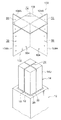
図1及び図2に示されるように、下柱部材12の上端面には、上柱部材42及び鉄骨梁30が接合される鋼製の接合治具50が取り付けられる。つまり、下柱部材12は、上端に金属製の接合治具50を有している。接合治具50は、治具本体部52と、治具本体部52の下端部に設けられた下フランジ部60と、治具本体部52の上端部に設けられた上フランジ部70とを有している。
(Composition of joining jig)
As shown in FIGS. 1 and 2, a steel joining jig 50 to which the upper pillar member 42 and the steel beam 30 are joined is attached to the upper end surface of the lower pillar member 12. That is, the lower column member 12 has a metal joining jig 50 at the upper end. The joining jig 50 includes a jig body 52, a lower flange 60 provided at the lower end of the jig body 52, and an upper flange 70 provided at the upper end of the jig body 52. doing.

治具本体部52は断面十字状に形成されており、その中央部において互いに交差(本実施形態では直交)する2枚の取付プレート54を有している。各取付プレート54の外側の端部は、鉄骨梁30の突出部34Aが取り付けられる梁取付部54Aとされている。各梁取付部54Aには、複数のボルト孔56が上下方向に間隔を空けて形成されている。これらの梁取付部54Aには、鉄骨梁30の突出部34Aが重ね合わせられる。この状態で、突出部34A及び梁取付部54Aのボルト孔38,56にボルト36(図3参照)を挿入して図示しないナットと締結することにより、梁取付部54Aに突出部34Aが接合されるようになっている。   The jig main body 52 is formed in a cross shape in cross section, and has two mounting plates 54 that intersect each other (in the present embodiment, orthogonal) at the center thereof. The outer end of each mounting plate 54 is a beam mounting portion 54A to which the protruding portion 34A of the steel beam 30 is mounted. A plurality of bolt holes 56 are formed in each beam mounting portion 54A at intervals in the vertical direction. The projecting portions 34A of the steel beam 30 are superimposed on these beam attachment portions 54A. In this state, by inserting the bolt 36 (see FIG. 3) into the bolt holes 38 and 56 of the protrusion 34A and the beam attachment portion 54A and fastening with a nut (not shown), the protrusion 34A is joined to the beam attachment portion 54A. It has become so.

また、各取付プレート54の下部における中央部には、後述する下フランジ部60の中央部に形成された位置決め用孔62を露出させる一対のU字状の溝部58が形成されている。   In addition, a pair of U-shaped groove portions 58 that expose positioning holes 62 formed in the center portion of the lower flange portion 60 described later are formed in the center portion at the lower portion of each mounting plate 54.

図3に示されるように、下フランジ部60は矩形の鋼板で形成されており、下柱部材12の心部14の上面に重ねられる。この下フランジ部60の中央部には円形の位置決め用孔62が形成されている。この位置決め用孔62に挿入されたラグスクリュー64を心部14の中央部に形成された取付孔24に捻じ込むことにより、下フランジ部60の中央部が下柱部材12に固定されるようになっている。   As shown in FIG. 3, the lower flange portion 60 is formed of a rectangular steel plate and overlaps the upper surface of the core portion 14 of the lower column member 12. A circular positioning hole 62 is formed at the center of the lower flange portion 60. By screwing the lag screw 64 inserted into the positioning hole 62 into the mounting hole 24 formed in the central portion of the core portion 14, the central portion of the lower flange portion 60 is fixed to the lower column member 12. It has become.

なお、位置決め用孔62は、心部14に対する下フランジ部60の固定位置を調整可能なルーズ孔とされている。これにより、ラグスクリュー64を仮止めした状態で、接合治具50が心部14に対して水平二方向(図2おいて矢印X方向及び矢印Y方向)へ移動可能になると共に、ラグスクリュー64を回転軸として回転可能(図2において矢印R方向)になっている。   The positioning hole 62 is a loose hole that can adjust the fixing position of the lower flange portion 60 with respect to the core portion 14. Accordingly, the joining jig 50 can move in two horizontal directions (arrow X direction and arrow Y direction in FIG. 2) with respect to the core portion 14 with the lag screw 64 temporarily fixed, and the lag screw 64. Is rotatable about the rotation axis (in the direction of arrow R in FIG. 2).

さらに、下フランジ部60の四隅には、取付孔66がそれぞれ形成されている。これらの取付孔66に挿入されたラグスクリュー68を下柱部材12の心部14の外周部に捻じ込むことにより、下フランジ部60の四隅が心部14に固定されるようになっている。   Further, attachment holes 66 are formed at the four corners of the lower flange portion 60, respectively. The four corners of the lower flange portion 60 are fixed to the core portion 14 by screwing the lag screws 68 inserted into the mounting holes 66 into the outer peripheral portion of the core portion 14 of the lower column member 12.

一方、接合治具50の上フランジ部70は矩形の鋼板で形成されており、その四隅に取付孔72がそれぞれ形成されている。この上フランジ部70の上には、上柱部材42の下端面に設けられたベースプレート44が重ねられる。ベースプレート44には取付孔46が形成されており、このベースプレート44を上フランジ部70に重ねた状態で取付孔46,72に挿入されたラグスクリュー48を上柱部材42の下面に捻じ込むことにより、上フランジ部70に上柱部材42が固定されるようになっている。なお、ベースプレート44は、適宜省略可能である。また、本実施形態では、上柱部材42は下柱部材12と同様の構成とされている。   On the other hand, the upper flange portion 70 of the joining jig 50 is formed of a rectangular steel plate, and attachment holes 72 are formed at the four corners thereof. A base plate 44 provided on the lower end surface of the upper column member 42 is overlaid on the upper flange portion 70. A mounting hole 46 is formed in the base plate 44, and the lag screw 48 inserted into the mounting holes 46 and 72 is screwed into the lower surface of the upper column member 42 in a state where the base plate 44 is overlapped with the upper flange portion 70. The upper pillar member 42 is fixed to the upper flange portion 70. The base plate 44 can be omitted as appropriate. In the present embodiment, the upper column member 42 has the same configuration as the lower column member 12.

(コンクリート硬化体)
図4に示されるように、接合治具50は、下柱部材12の仕口部12Sを構成するコンクリート硬化体80によって被覆(耐火被覆)されている。換言すると、接合治具50は、コンクリート硬化体80に埋設されている。コンクリート硬化体80は、接合治具50の各梁取付部54Aに鉄骨梁30の突出部34Aを取り付けた状態で、接合治具50の周囲にコンクリートを打設することにより形成される。
(Hardened concrete)
As shown in FIG. 4, the joining jig 50 is covered (fireproof coating) with a hardened concrete body 80 constituting the joint portion 12 </ b> S of the lower column member 12. In other words, the joining jig 50 is embedded in the hardened concrete body 80. The hardened concrete body 80 is formed by placing concrete around the joining jig 50 in a state where the protruding portions 34A of the steel beam 30 are attached to the beam attaching parts 54A of the joining jig 50.

コンクリート硬化体80の四隅には、上下方向に延びる軸鉄筋82がそれぞれ埋設されている。また、コンクリート硬化体80には、複数の軸鉄筋82を結束する複数のせん断補強筋84が埋設されている。これらのせん断補強筋84は、複数の軸鉄筋82を囲むと共に、上下方向に間隔を空けて配筋されている。なお、複数のせん断補強筋84のうち、最上段及び最下段以外のせん断補強筋84は、鉄骨梁30の突出部34Aに形成された貫通孔40に貫通されている。   In the four corners of the hardened concrete body 80, shaft reinforcing bars 82 extending in the vertical direction are respectively embedded. In addition, a plurality of shear reinforcement bars 84 that bind a plurality of shaft reinforcing bars 82 are embedded in the hardened concrete body 80. These shear reinforcing bars 84 surround the plurality of shaft reinforcing bars 82 and are arranged at intervals in the vertical direction. Note that, among the plurality of shear reinforcement bars 84, the shear reinforcement bars 84 other than the uppermost stage and the lowermost stage are penetrated through the through holes 40 formed in the protruding portion 34 </ b> A of the steel beam 30.

次に、本実施形態に係る柱梁接合構造の施工方法の一例について説明する。   Next, an example of the construction method of the column beam connection structure according to the present embodiment will be described.

先ず、図2に示されるように、所定位置に立てられた下柱部材12の心部14の上に、接合治具50の下フランジ部60を載置し、重ね合わせる。次に、下フランジ部60の位置決め用孔62(図3参照)を介して心部14の取付孔24にラグスクリュー64を捻じ込み、下フランジ部60を心部14に仮止めする。   First, as shown in FIG. 2, the lower flange portion 60 of the joining jig 50 is placed on the core portion 14 of the lower column member 12 erected at a predetermined position and overlapped. Next, a lag screw 64 is screwed into the mounting hole 24 of the core part 14 through the positioning hole 62 (see FIG. 3) of the lower flange part 60 to temporarily fix the lower flange part 60 to the core part 14.

次に、図3に示されるように、接合治具50の梁取付部54Aに鉄骨梁30の突出部34Aを重ね合わせる。この際、接合治具50を位置決め用孔62及びラグスクリュー64が許容する範囲内で水平二方向(図2において矢印X方向及び矢印Y方向)へ移動させ、若しくはラグスクリュー64を回転軸として回転(図2において矢印R方向)させることにより、取付プレート54に突出部34Aを重ね合わせる。この状態で、取付プレート54及び突出部34Aのボルト孔38,56にボルト36を挿入すると共に、ボルト36に図示しないナットを取り付け、取付プレート54と突出部34Aと仮止めする。この手順を繰り返し、接合治具50の4つの梁取付部54Aに4本の鉄骨梁30の突出部34Aをそれぞれ仮止めする。   Next, as shown in FIG. 3, the protruding portion 34 </ b> A of the steel beam 30 is overlapped with the beam mounting portion 54 </ b> A of the joining jig 50. At this time, the joining jig 50 is moved in two horizontal directions (arrow X direction and arrow Y direction in FIG. 2) within the range allowed by the positioning hole 62 and the lag screw 64, or rotated around the lag screw 64 as a rotation axis. By projecting (in the direction of arrow R in FIG. 2), the protrusion 34 </ b> A is superimposed on the mounting plate 54. In this state, the bolt 36 is inserted into the bolt holes 38 and 56 of the mounting plate 54 and the protruding portion 34A, and a nut (not shown) is attached to the bolt 36 to temporarily fix the mounting plate 54 and the protruding portion 34A. This procedure is repeated, and the protruding portions 34A of the four steel beams 30 are temporarily fixed to the four beam attachment portions 54A of the joining jig 50, respectively.

次に、下フランジ部60の位置決め用孔62に挿入されたラグスクリュー64を下柱部材12の心部14に本締めすると共に、下フランジ部60の四隅に形成された取付孔66を介してラグスクリュー68を下柱部材12の心部14に本締めする。これにより、下柱部材12の心部14に接合治具50が固定される。   Next, the lag screw 64 inserted into the positioning hole 62 of the lower flange portion 60 is finally tightened to the core portion 14 of the lower column member 12, and through the attachment holes 66 formed at the four corners of the lower flange portion 60. The lag screw 68 is finally tightened to the center part 14 of the lower column member 12. Thereby, the joining jig 50 is fixed to the core part 14 of the lower column member 12.

次に、接合治具50の梁取付部54Aと鉄骨梁30の突出部34Aとを接合するボルト36を本締めし、接合治具50を介して鉄骨梁30を下柱部材12に接合する。次に、接合治具50の上フランジ部70の上に上柱部材42のベースプレート44を載置する。そして、上フランジ部70及びベースプレート44に形成された取付孔46,72を介してラグスクリュー48を上柱部材42に下面に捻じ込み、上フランジ部70に上柱部材42を固定する。   Next, the bolt 36 that joins the beam attachment portion 54 </ b> A of the joining jig 50 and the protruding portion 34 </ b> A of the steel beam 30 is finally tightened, and the steel beam 30 is joined to the lower column member 12 via the joining jig 50. Next, the base plate 44 of the upper column member 42 is placed on the upper flange portion 70 of the joining jig 50. Then, the lag screw 48 is screwed onto the lower surface of the upper column member 42 through the mounting holes 46 and 72 formed in the upper flange portion 70 and the base plate 44, and the upper column member 42 is fixed to the upper flange portion 70.

次に、接合治具50の周囲に軸鉄筋82及びせん断補強筋84を配筋した後、接合治具50を囲むように下柱部材12及び上柱部材42の外周面に沿って型枠を仮設し、コンクリートを打設してコンクリート硬化体80を形成する。このコンクリート硬化体80によって接合治具50が耐火被覆されると共に、下柱部材12の仕口部12Sが形成される。   Next, after the shaft reinforcing bars 82 and the shear reinforcement bars 84 are arranged around the joining jig 50, the mold frame is formed along the outer peripheral surfaces of the lower column member 12 and the upper column member 42 so as to surround the joining jig 50. Temporary and concrete is cast to form a hardened concrete body 80. The hardened concrete 80 covers the joining jig 50 in a fireproof manner, and forms the joint 12S of the lower column member 12.

次に、吹き付けロックウール等の耐火被覆材等によって4本の鉄骨梁30をそれぞれ耐火被覆する。   Next, the four steel beams 30 are fire-resistant coated with a fire-resistant covering material such as spray rock wool.

次に、本実施形態に係る柱梁接合構造の作用について説明する。   Next, the operation of the column beam joint structure according to the present embodiment will be described.

下柱部材12には、耐火構造が適用されている。具体的には、図4に示されるように、下柱部材12の心部14は、燃え止まり層16及び燃え代層18によって被覆されている。したがって、火災時には、先ず、燃え代層18が徐々に燃焼して燃え止まり層16の周囲に炭化層(断熱層)を形成する。これにより、心部14への熱の侵入(熱伝達)が抑制される。また、心部14よりも熱容量が大きい燃え止まり層16によって火災熱が吸収(吸熱)される。これにより、燃え代層18の燃焼速度(炭化速度)が減速されると共に、心部14の温度上昇がさらに低減される。したがって、心部14の燃焼が抑制されるため、火災時に心部14に長期荷重を支持させることができる。   A fireproof structure is applied to the lower column member 12. Specifically, as shown in FIG. 4, the core portion 14 of the lower column member 12 is covered with a flame stop layer 16 and a burn allowance layer 18. Therefore, in the event of a fire, first, the burning allowance layer 18 gradually burns to form a carbonized layer (heat insulating layer) around the flame stop layer 16. Thereby, the penetration | invasion (heat transfer) of the heat | fever to the core part 14 is suppressed. In addition, fire heat is absorbed (heat absorption) by the flame stop layer 16 having a larger heat capacity than the core portion 14. As a result, the combustion rate (carbonization rate) of the combustion allowance layer 18 is reduced, and the temperature rise of the core 14 is further reduced. Therefore, since the combustion of the core part 14 is suppressed, a long-term load can be supported by the core part 14 at the time of a fire.

さらに、燃え止まり層16において燃え代層18の燃焼を停止(自然鎮火)させることができる。したがって、火災終了後も心部14に長期荷重を支持させることができる。   Furthermore, the combustion of the burning allowance layer 18 can be stopped in the burning stop layer 16 (natural quenching). Therefore, a long-term load can be supported on the core 14 even after the end of the fire.

一方、下柱部材12と鉄骨梁30と接合する鋼製の接合治具50は、下柱部材12の仕口部12Sを構成するコンクリート硬化体80に埋設されている。つまり、接合治具50は、コンクリート硬化体80によって被覆されている。   On the other hand, a steel joining jig 50 that joins the lower column member 12 and the steel beam 30 is embedded in a hardened concrete body 80 constituting the joint portion 12S of the lower column member 12. That is, the joining jig 50 is covered with the hardened concrete body 80.

ここで、コンクリート硬化体80は木材と比較して燃焼し難く、かつ熱容量が大きい。このコンクリート硬化体80によって接合治具50を被覆することにより、火災時における接合治具50の温度上昇が抑制される。これにより、接合治具50の熱劣化が抑制される。したがって、下柱部材12と鉄骨梁30との仕口部12Sの耐火性能が向上する。   Here, the hardened concrete body 80 is less likely to burn than wood and has a large heat capacity. By covering the joining jig 50 with the hardened concrete 80, the temperature rise of the joining jig 50 during a fire is suppressed. Thereby, the thermal deterioration of the joining jig 50 is suppressed. Therefore, the fire resistance performance of the joint portion 12S between the lower column member 12 and the steel beam 30 is improved.

このように本実施形態に係る柱梁接合構造10では、下柱部材12と鉄骨梁30との接合強度を確保しつつ、下柱部材12と鉄骨梁30との仕口部12Sの耐火性能を向上させることができる。   Thus, in the column beam joint structure 10 according to the present embodiment, the fire resistance of the joint portion 12S between the lower column member 12 and the steel beam 30 is ensured while ensuring the joint strength between the lower column member 12 and the steel beam 30. Can be improved.

また、接合治具50の下フランジ部60には、位置決め用孔62が形成されている。位置決め用孔62はルーズ孔とされており、この位置決め用孔62を介してラグスクリュー64を下柱部材12の心部14に仮止めした状態では、接合治具50が心部14に対して水平二方向(図2において矢印X方向及び矢印Y方向)へ移動可能になると共に、ラグスクリュー64を回転軸として回転可能(図2において矢印R方向)になる。これにより、接合治具50の梁取付部54Aと鉄骨梁30の突出部34Aとの位置決め作業が容易となる。したがって、施工性が向上する。   Further, a positioning hole 62 is formed in the lower flange portion 60 of the joining jig 50. The positioning hole 62 is a loose hole. When the lag screw 64 is temporarily fixed to the core portion 14 of the lower column member 12 through the positioning hole 62, the joining jig 50 is attached to the core portion 14. It can move in two horizontal directions (arrow X direction and arrow Y direction in FIG. 2) and can rotate around the lag screw 64 as a rotation axis (arrow R direction in FIG. 2). Thereby, the positioning operation | work of the beam attaching part 54A of the joining jig 50 and the protrusion part 34A of the steel beam 30 becomes easy. Therefore, the workability is improved.

さらに、接合治具50の下フランジ部60は、下柱部材12の心部14に接合(固定)されている。これにより、接合治具50を介して上柱部材42から下柱部材12の心部14に軸力(鉛直荷重)及びせん断力を伝達することができる。   Further, the lower flange portion 60 of the joining jig 50 is joined (fixed) to the core portion 14 of the lower column member 12. Thereby, an axial force (vertical load) and a shearing force can be transmitted from the upper column member 42 to the core portion 14 of the lower column member 12 via the joining jig 50.

次に、上記実施形態に係る柱梁接合構造の変形例について説明する。なお、上記実施形態と同様の構成のものは同符号を付すると共に、適宜省略して説明する。   Next, a modified example of the column beam joint structure according to the embodiment will be described. In addition, the thing of the structure similar to the said embodiment attaches | subjects a same sign, and abbreviate | omits suitably and demonstrates.

上記実施形態では、接合治具50を介して鉄骨梁30を下柱部材12に力学的にピン接合し、鉄骨梁30から下柱部材12に曲げモーメントを伝達しない例を示したが、これに限らない。例えば、図5に示されるように、鉄骨梁30から下柱部材12へ曲げモーメントを伝達するアンカー部材86をコンクリート硬化体80に埋設しても良い。   In the above embodiment, the steel beam 30 is mechanically pin-joined to the lower column member 12 via the joining jig 50 and the bending moment is not transmitted from the steel beam 30 to the lower column member 12. Not exclusively. For example, as shown in FIG. 5, an anchor member 86 that transmits a bending moment from the steel beam 30 to the lower column member 12 may be embedded in the hardened concrete body 80.

具体的には、複数の固定部材としての複数のアンカー部材86は、上下方向に延びる鉄筋等で形成されており、コンクリート硬化体80と下柱部材12の心部14とに亘って配置されている。各アンカー部材86の下部86Lは、接合治具50の下フランジ部60の四隅をそれぞれ貫通し、下柱部材12の心部14に外周部に打ち込まれている。一方、アンカー部材86の上部86Uは、コンクリート硬化体80に埋設されている。これらのアンカー部材86によって、下柱部材12の心部14にコンクリート硬化体80が固定されている。   Specifically, the plurality of anchor members 86 as the plurality of fixing members are formed of reinforcing bars or the like extending in the vertical direction, and are arranged across the hardened concrete body 80 and the core portion 14 of the lower column member 12. Yes. The lower portion 86L of each anchor member 86 passes through the four corners of the lower flange portion 60 of the joining jig 50 and is driven into the outer peripheral portion of the core portion 14 of the lower column member 12. On the other hand, the upper portion 86 </ b> U of the anchor member 86 is embedded in the hardened concrete body 80. The hardened concrete body 80 is fixed to the core portion 14 of the lower column member 12 by these anchor members 86.

これにより、各アンカー部材86の引張り力によって鉄骨梁30から下柱部材12の心部14へ曲げモーメントが伝達されるため、仕口部12Sに対する鉄骨梁30の端部の固定度が上がる。したがって、常時及び地震時における鉄骨梁30の変形が抑制されるため、居住性及び耐震性能が向上する。   Thereby, since the bending moment is transmitted from the steel beam 30 to the core part 14 of the lower column member 12 by the tensile force of each anchor member 86, the degree of fixation of the end of the steel beam 30 with respect to the joint portion 12S increases. Therefore, since the deformation of the steel beam 30 at all times and during an earthquake is suppressed, the comfortability and seismic performance are improved.

なお、固定部材は、上記したアンカー部材86に限らない。固定部材は、鉄骨梁30から下柱部材12へ曲げモーメントを伝達可能な部材であれば良く、例えば、上部がL字状、J字状に屈曲されたコンクリートアンカー等を用いても良い。また、固定部材の配置や本数は適宜変更可能であり、例えば、アンカー部材86を燃え止まり層16や燃え代層18に固定しても良い。また、軸鉄筋82の下部を下柱部材12へ延出させ、固定部材として流用しても良い。   The fixing member is not limited to the anchor member 86 described above. The fixing member may be any member that can transmit a bending moment from the steel beam 30 to the lower column member 12. For example, a concrete anchor whose upper portion is bent in an L shape or a J shape may be used. Further, the arrangement and number of the fixing members can be appropriately changed. For example, the anchor member 86 may be fixed to the flame stop layer 16 or the burn allowance layer 18. Further, the lower part of the shaft reinforcing bar 82 may be extended to the lower column member 12 and used as a fixing member.

さらに、固定部材によって接合治具50を下柱部材12に固定し、鉄骨梁30から下柱部材12へ曲げモーメントを伝達しても良い。   Further, the joining jig 50 may be fixed to the lower column member 12 by a fixing member, and a bending moment may be transmitted from the steel beam 30 to the lower column member 12.

次に、接合治具50の構成は上記したものに限らず、適宜変更可能である。例えば、図6に示される接合治具90は、治具本体部91を有している。治具本体部91は、その中央部で互いに交差(本変形例では直交)する2本のH形鋼92を有している。各H形鋼92は、上下一対のフランジ部94と、上下一対のフランジ部94を繋ぐウェブ部96とを有している。   Next, the configuration of the joining jig 50 is not limited to the above, and can be changed as appropriate. For example, the joining jig 90 shown in FIG. 6 has a jig body 91. The jig main body 91 has two H-sections 92 that intersect each other (orthogonal in the present modification) at the center thereof. Each H-shaped steel 92 has a pair of upper and lower flange portions 94 and a web portion 96 that connects the pair of upper and lower flange portions 94.

H形鋼92の端部は、下柱部材12の上端面から外側(鉄骨梁30側)へ延出しており、鉄骨梁30(図1参照)の端部が剛接合される梁取付部92Aとされている。この梁取付部92Aにおけるウェブ部96には、複数のボルト孔56が上下方向に間隔を空けて形成されており、鉄骨梁30の突出部34Aが重ねられた状態でボルト36及びナットより接合される。また、梁取付部92Aにおける上下一対のフランジ部94には、鉄骨梁30の上下一対のフランジ部32が溶接等により接合される。これにより、各梁取付部92Aに鉄骨梁30の端部が曲げモーメントを伝達可能に剛接合される。   The end of the H-shaped steel 92 extends from the upper end surface of the lower column member 12 to the outside (the steel beam 30 side), and the beam attachment portion 92A to which the end of the steel beam 30 (see FIG. 1) is rigidly joined. It is said that. A plurality of bolt holes 56 are formed in the web portion 96 of the beam attachment portion 92A at intervals in the vertical direction, and are joined by bolts 36 and nuts in a state where the protruding portions 34A of the steel beam 30 are overlapped. The The pair of upper and lower flange portions 32 of the steel beam 30 are joined to the pair of upper and lower flange portions 94 of the beam attachment portion 92A by welding or the like. As a result, the end of the steel beam 30 is rigidly joined to each beam attachment portion 92A so that a bending moment can be transmitted.

一方、治具本体部91の中央部には、コンクリートが打設され、下柱部材12の仕口部12Sを構成するコンクリート硬化体98が形成される。このコンクリート硬化体98によって、治具本体部91の中央部が被覆(耐火被覆)される。なお、下柱部材12の上端面から外側(鉄骨梁30側)へ延出されたH形鋼92の梁取付部92Aは、鉄骨梁30と共にロックウール等の耐火被覆材によって耐火被覆される。   On the other hand, concrete is cast in the central portion of the jig main body 91 to form a hardened concrete body 98 that forms the joint portion 12 </ b> S of the lower column member 12. The center portion of the jig main body 91 is covered (fireproof coating) by the hardened concrete body 98. Note that the beam attachment portion 92A of the H-shaped steel 92 extending from the upper end surface of the lower column member 12 to the outside (the steel beam 30 side) is covered with the steel beam 30 with a fireproof coating material such as rock wool.

このようにH形鋼92の両側の梁取付部92Aに2本の鉄骨梁30の端部をそれぞれ剛接合することにより、H形鋼92を介して2本の鉄骨梁30の間で曲げモーメントが伝達される。これにより、2本の鉄骨梁30の端部に発生する曲げモーメントが小さくなる。したがって、鉄骨梁30の梁成等を小さくすることができる。   In this way, by bending the end portions of the two steel beams 30 to the beam attachment portions 92A on both sides of the H-shaped steel 92, the bending moment between the two steel beams 30 via the H-shaped steel 92 is obtained. Is transmitted. Thereby, the bending moment which generate | occur | produces in the edge part of the two steel beam 30 becomes small. Therefore, the beam formation of the steel beam 30 can be reduced.

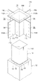
次に、図7及び図8に示される接合治具100は、治具本体部102と、治具本体部102の上端部に設けられた上フランジ部106とを有している。治具本体部102は、断面十字状に形成されており、その中央部で互いに交差(本変形例では直交)する2枚の取付プレート104を有している。   Next, the joining jig 100 shown in FIGS. 7 and 8 has a jig body 102 and an upper flange portion 106 provided at the upper end of the jig body 102. The jig body 102 is formed in a cross shape in cross section, and has two mounting plates 104 that intersect each other (orthogonal in the present modification) at the center.

各取付プレート104の外側の端部は、下柱部材12の上端面から外側へ延出しており、鉄骨梁30の突出部34A(図1参照)が接合される梁取付部104Aとされている。この梁取付部104Aには、複数のボルト孔56が上下方向に間隔を空けて形成されている。   The outer end portion of each mounting plate 104 extends outward from the upper end surface of the lower column member 12, and serves as a beam mounting portion 104A to which the protruding portion 34A (see FIG. 1) of the steel beam 30 is joined. . A plurality of bolt holes 56 are formed in the beam mounting portion 104A at intervals in the vertical direction.

上フランジ部106は、平面視にて矩形に形成されており、2枚の取付プレート104の上端部に接合されている。この上フランジ部106には、上柱部材42のベースプレート44(図1参照)が接合されるようになっている。   The upper flange portion 106 is formed in a rectangular shape in plan view, and is joined to the upper end portions of the two mounting plates 104. A base plate 44 (see FIG. 1) of the upper column member 42 is joined to the upper flange portion 106.

一方、下柱部材12の上端面からは、心部14の上端部14Uが上方へ突出している。この心部14の上端部14Uには、平面視にて十字状の溝部26が形成されている。図8に示されるように、この溝部26に接合治具100の治具本体部102を挿入し、接合治具100の上フランジ部106を心部14の上端面に係止(載置)することにより、心部14の上端部14Uに治具本体部102が取り付けられる(接合される)。なお、治具本体部102は、図示しないラグスクリュー等によって心部14の上端部14Uに固定しても良い。   On the other hand, from the upper end surface of the lower column member 12, the upper end portion 14U of the core portion 14 protrudes upward. A cross-shaped groove portion 26 is formed in the upper end portion 14U of the center portion 14 in plan view. As shown in FIG. 8, the jig body portion 102 of the joining jig 100 is inserted into the groove portion 26, and the upper flange portion 106 of the joining jig 100 is locked (placed) on the upper end surface of the core portion 14. Thus, the jig main body 102 is attached (joined) to the upper end portion 14U of the core portion 14. The jig main body 102 may be fixed to the upper end portion 14U of the core portion 14 with a lag screw or the like (not shown).

また、心部14の上端部14Uの周囲には、コンクリートが打設され、下柱部材12の仕口部12Sを構成するコンクリート硬化体108が形成される。このコンクリート硬化体108によって、治具本体部102及び心部14の上端部14Uが被覆(耐火被覆)される。なお、下柱部材12の上端面から外側へ延出する治具本体部102の梁取付部104Aは、鉄骨梁30と共にロックウール等の耐火被覆材によって耐火被覆される。   Further, concrete is cast around the upper end portion 14U of the core portion 14 to form a hardened concrete body 108 that forms the joint portion 12S of the lower column member 12. The hardened concrete body 108 covers (fireproof) the jig main body 102 and the upper end portion 14U of the core portion 14. Note that the beam attachment portion 104 </ b> A of the jig main body 102 extending outward from the upper end surface of the lower column member 12 is fire-resistant coated with a fire-resistant covering material such as rock wool together with the steel beam 30.

このように心部14の上端部14Uに接合治具100を取り付けることより、接合治具100を介して上柱部材42(図1参照)から下柱部材12の心部14に軸力(長期軸力)が伝達される。   By attaching the joining jig 100 to the upper end portion 14U of the core part 14 in this way, an axial force (long term) is applied from the upper column member 42 (see FIG. 1) to the core part 14 of the lower column member 12 via the joining jig 100. Axial force) is transmitted.

また、接合治具100の上フランジ部106を心部14の上端面に係止することにより、上柱部材42からの軸力が心部14へ分散して伝達されるため、下柱部材12に対する取付プレート104のめり込みが抑制される。   Further, by locking the upper flange portion 106 of the joining jig 100 to the upper end surface of the core portion 14, the axial force from the upper column member 42 is distributed and transmitted to the core portion 14. The fitting of the mounting plate 104 to is suppressed.

さらに、心部14の上端部14U及び治具本体部102の中央部をコンクリート硬化体108に埋設することにより、火災時における心部14及び接合治具100の温度上昇が抑制される。したがって、下柱部材12の仕口部12Sの耐火性能が向上する。   Furthermore, by embedding the upper end portion 14U of the core portion 14 and the central portion of the jig main body portion 102 in the hardened concrete body 108, the temperature rise of the core portion 14 and the joining jig 100 during a fire is suppressed. Therefore, the fire resistance performance of the joint portion 12S of the lower column member 12 is improved.

なお、本変形例では、心部14に形成された溝部26に治具本体部102を挿入した例を示したが、これに限らない。例えば、例えば、図9及び図10に示されるように、接合治具110の治具本体部112の中央部に角形の筒状部114を設け、当該筒状部114に心部14の上端部14Uを挿入しても良い(嵌め込んでも良い)。なお、筒状部114の各側面には、取付プレート116が設けられている。これらの取付プレート116の外側の端部は、梁取付部116Aとされている。   In addition, in this modification, although the example which inserted the jig | tool main body part 102 in the groove part 26 formed in the core part 14 was shown, it does not restrict to this. For example, as shown in FIG. 9 and FIG. 10, for example, a rectangular cylindrical portion 114 is provided at the center of the jig main body 112 of the joining jig 110, and the upper end of the core portion 14 is provided in the cylindrical portion 114. 14U may be inserted (it may be inserted). A mounting plate 116 is provided on each side surface of the cylindrical portion 114. The outer ends of these mounting plates 116 are beam mounting portions 116A.

このような接合治具110では、心部14に溝部26を形成する必要がないため、下柱部材12の製作コストを削減することができる。また、筒状部114によって心部14の上端部14Uが拘束されるため、当該上端部14Uの軸耐力等を高めることができる。   In such a joining jig 110, since it is not necessary to form the groove part 26 in the center part 14, the manufacturing cost of the lower pillar member 12 can be reduced. Moreover, since the upper end part 14U of the center part 14 is restrained by the cylindrical part 114, the axial yield strength etc. of the said upper end part 14U can be improved.

また、上記実施形態では、鋼製の接合治具50を用いた例を示したが、接合治具50は金属製であれば良く、例えば、鉄やアルミニウム等で形成しても良い。   Moreover, although the example using the steel joining jig | tool 50 was shown in the said embodiment, the joining jig | tool 50 should just be metal, for example, may form with iron, aluminum, etc.

次に、上記実施形態では、木質柱部材として三層構造(心部14、燃え止まり層16、燃え代層18)を有する下柱部材12を例に説明したが、これに限らない。木質柱部材は、その少なくとも一部が木材で形成され、かつ耐火構造又は準耐火構造が適用されていれば良く、例えば、下柱部材12において燃え止まり層16及び燃え代層18の何れか一方を省略しても良い。   Next, although the said embodiment demonstrated the lower pillar member 12 which has a three-layer structure (the core part 14, the burning stop layer 16, and the burning allowance layer 18) as an example of a wooden pillar member, it does not restrict to this. The wooden column member only needs to be at least partly formed of wood and applied with a fireproof structure or a quasi-fireproof structure. For example, one of the flame stop layer 16 and the burn allowance layer 18 in the lower column member 12. May be omitted.

また、木質柱部材としては、無耐火の木製の柱部材を耐火被覆材で耐火被覆したものを用いても良い。この耐火被覆材としては、例えば、耐火塗料、けい酸カルシウム板、石膏ボード、コンクリートボード、ロックウールボート等が挙げられる。   Further, as the wooden pillar member, a fire-resistant wooden pillar member covered with a fire-resistant coating material may be used. Examples of the fireproof coating material include fireproof paint, calcium silicate board, gypsum board, concrete board, rock wool boat, and the like.

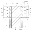
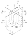
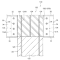
また、例えば、木質柱部材としては、内部に鉄骨心材が埋設された木質ハイブリッド柱部材を用いても良い。具体的には、図11及び図12に示されるように、木質柱部材としての下柱部材120は木質ハイブリッド柱部材で形成されており、木製の柱部材122と、H形鋼で形成され、柱部材122の中央部に埋設された鉄骨心材124とを有している。柱部材122は、前述した集成材によって形成されている。この柱部材122によって鉄骨心材124が被覆(耐火被覆)されており、火災時に柱部材122が燃焼して炭化層(断熱層)を形成することにより、鉄骨心材124の温度上昇が抑制されるようになっている。つまり、柱部材122は、燃え代層(被覆部)として機能するようになっている。   Further, for example, as the wooden column member, a wooden hybrid column member in which a steel core material is embedded may be used. Specifically, as shown in FIGS. 11 and 12, the lower pillar member 120 as the wooden pillar member is formed of a wooden hybrid pillar member, and is formed of a wooden pillar member 122 and H-shaped steel, And a steel core material 124 embedded in the center of the column member 122. The column member 122 is formed of the laminated material described above. The steel core material 124 is covered (fireproof coating) by the column member 122, and the column member 122 burns to form a carbonized layer (heat insulating layer) in the event of a fire so that the temperature rise of the steel core material 124 is suppressed. It has become. That is, the column member 122 functions as a burning allowance layer (covering portion).

鉄骨心材124の上端部124Uは、柱部材122の上端面から上方へ突出しており、鉄骨梁30(図1参照)が接合される接合治具130の治具本体部132の一部を構成している。つまり、下柱部材120は、その上端に金属製の接合治具130を有している。具体的には、鉄骨心材124の上端部124Uにおけるウェブ部126の両面には、取付プレート134がそれぞれ設けられている。また、鉄骨心材124の上端部124Uにおけるフランジ部128には、取付プレート134がそれぞれ設けられている。つまり、治具本体部132は、鉄骨心材124の上端部124Uと、上端部124Uに設けられた4枚の取付プレート134とを有して構成されている。   The upper end portion 124U of the steel core member 124 protrudes upward from the upper end surface of the column member 122, and constitutes a part of the jig main body 132 of the joining jig 130 to which the steel beam 30 (see FIG. 1) is joined. ing. That is, the lower column member 120 has a metal joining jig 130 at its upper end. Specifically, attachment plates 134 are provided on both surfaces of the web portion 126 at the upper end portion 124U of the steel core material 124, respectively. Moreover, the attachment plate 134 is provided in the flange part 128 in the upper end part 124U of the steel core material 124, respectively. In other words, the jig main body 132 includes the upper end portion 124U of the steel core member 124 and the four attachment plates 134 provided on the upper end portion 124U.

各取付プレート134の端部は、鉄骨梁30が接合される梁取付部134Aとされている。また、図12に示されるように、接合治具130の中央部には、コンクリートが打設され、下柱部材120の仕口部120Sを構成するコンクリート硬化体136が形成されている。このコンクリート硬化体136によって、治具本体部132の中央部が被覆(耐火被覆)されている。これにより、火災時における接合治具130の温度上昇が抑制される。したがって、下柱部材120と鉄骨梁30との仕口部120Sの耐火性能が向上する。   An end portion of each attachment plate 134 is a beam attachment portion 134A to which the steel beam 30 is joined. In addition, as shown in FIG. 12, concrete is cast at the center of the joining jig 130, and a hardened concrete body 136 that forms the joint 120 </ b> S of the lower column member 120 is formed. The center portion of the jig main body 132 is covered (fireproof coating) by the hardened concrete 136. Thereby, the temperature rise of the joining jig 130 at the time of a fire is suppressed. Therefore, the fire resistance performance of the joint 120S between the lower column member 120 and the steel beam 30 is improved.

このように接合治具130は、木質柱部材としての下柱部材120と一体に形成されていても良いし、上記実施形態のように木質柱部材としての下柱部材12(図1参照)と別体に形成されていても良い。つまり、上記実施形態における「上端に金属製の接合治具を有する木質柱部材」とは、上端に別体の接合治具が取り付けられた木質柱部材や、上端に接合治具が一体に形成された木質柱部材を含む概念である。   Thus, the joining jig 130 may be formed integrally with the lower pillar member 120 as the wooden pillar member, or with the lower pillar member 12 (see FIG. 1) as the wooden pillar member as in the above embodiment. It may be formed separately. In other words, the “wood pillar member having a metal joining jig at the upper end” in the above embodiment is a wooden pillar member having a separate joining jig attached to the upper end, or the joining jig is integrally formed at the upper end. It is the concept including the made wooden pillar member.

次に、上記実施形態では、接合治具50に4つの梁取付部54Aを設けた例を示したが、これに限らない。接合治具50には、少なくとも1つの梁取付部54Aがあれば良い。   Next, in the above-described embodiment, the example in which the four beam attaching portions 54A are provided in the joining jig 50 is shown, but the present invention is not limited to this. The joining jig 50 may have at least one beam attachment portion 54A.

また、上記実施形態では、接合治具50に上柱部材42を接合した例を示したが、接合治具50には上柱部材42を接合しなくても良い。つまり、接合治具50は、少なくとも下柱部材12と鉄骨梁30とを接合可能であれば良い。また、接合治具50と上柱部材42との接合構造は適宜変更可能である。さらに、接合治具50の上フランジ部70は、必要に応じて設ければ良く、適宜省略可能である。また、接合治具50の下フランジ部60に形成された位置決め用孔62は、適宜省略可能である。   Moreover, although the example which joined the upper pillar member 42 to the joining jig | tool 50 was shown in the said embodiment, the upper pillar member 42 does not need to be joined to the joining jig 50. FIG. That is, the joining jig 50 only needs to be able to join at least the lower column member 12 and the steel beam 30. Moreover, the joining structure of the joining jig 50 and the upper column member 42 can be changed as appropriate. Furthermore, the upper flange portion 70 of the joining jig 50 may be provided as necessary and can be omitted as appropriate. Further, the positioning hole 62 formed in the lower flange portion 60 of the joining jig 50 can be omitted as appropriate.

また、上記実施形態では、コンクリート硬化体80に軸鉄筋82及びせん断補強筋84を埋設した例を示したが、これに限らない。コンクリート硬化体80には、必要に応じて種々の補強筋を埋設することができる。さらに、軸鉄筋82及びせん断補強筋84等の補強筋は、省略しても良い。   Moreover, in the said embodiment, although the example in which the shaft reinforcement 82 and the shear reinforcement 84 were embed | buried in the concrete hardening body 80 was shown, it is not restricted to this. Various reinforcing bars can be embedded in the hardened concrete body 80 as necessary. Further, reinforcing bars such as the shaft reinforcing bar 82 and the shear reinforcing bar 84 may be omitted.

また、上記実施形態では、セメント系硬化体としてコンクリート硬化体80を例に説明したが、これに限らない。セメント系硬化体としては、モルタル硬化体やグラウト硬化体を用いても良い。   Moreover, in the said embodiment, although the concrete hardening body 80 was demonstrated to the example as a cement-type hardening body, it is not restricted to this. As the cement-based cured body, a mortar cured body or a grout cured body may be used.

また、上記実施形態では、下柱部材12の外形に合わせてコンクリート硬化体80を形成したが、これに限らない。コンクリート硬化体80等のセメント系硬化体の形状、大きさは、適宜変更可能である。また、セメント系硬化体の側面は、下柱部材12と同様の燃え代層で被覆しても良いし、木板等の仕上げ材で被覆しても良い。   Moreover, in the said embodiment, although the concrete hardening body 80 was formed according to the external shape of the lower pillar member 12, it is not restricted to this. The shape and size of the cement-based cured body such as the cured concrete body 80 can be appropriately changed. Further, the side surface of the cement-based cured body may be covered with a burning allowance layer similar to that of the lower column member 12 or may be covered with a finishing material such as a wooden board.

また、上記実施形態では、梁部材として鉄骨梁30を例に説明したが、これに限らない。梁部材としては、例えば、鉄筋コンクリート造、鉄骨コンクリート造、耐火構造又は準耐火構造が適用された木質梁部材を用いても良い。   Moreover, in the said embodiment, although the steel beam 30 was demonstrated to the example as a beam member, it is not restricted to this. As the beam member, for example, a wooden beam member to which a reinforced concrete structure, a steel concrete structure, a fireproof structure or a semi-fireproof structure is applied may be used.

以上、本発明の一実施形態について説明したが、本発明はこうした実施形態に限定されるものでなく、一実施形態及び各種の変形例を適宜組み合わせて用いても良いし、本発明の要旨を逸脱しない範囲において、種々なる態様で実施し得ることは勿論である。   As mentioned above, although one embodiment of the present invention was described, the present invention is not limited to such an embodiment, and one embodiment and various modifications may be used in combination as appropriate, and the gist of the present invention will be described. Of course, various embodiments can be implemented without departing from the scope.

10 柱梁接合構造
12 下柱部材(木質柱部材)
12S 仕口部
14 心部
16 燃え止まり層
18 燃え代層
30 鉄骨梁(梁部材)
50 接合治具
80 コンクリート硬化体(セメント系硬化体)
86 アンカー部材(固定部材)
90 接合治具
98 コンクリート硬化体
100 接合治具
108 コンクリート硬化体
110 接合治具
120 下柱部材(木質柱部材)
120S 仕口部
130 接合治具
10 Beam-column joint structure 12 Lower column member (woody column member)
12S Joint part 14 Core part 16 Burning stop layer 18 Burning allowance layer 30 Steel beam (beam member)
50 Joining jig 80 Hardened concrete (hardened cement)
86 Anchor member (fixing member)
90 Joining jig 98 Concrete hardened body 100 Joining jig 108 Concrete hardened body 110 Joining jig 120 Lower pillar member (woody pillar member)
120S Joint part 130 Joining jig

Claims (3)

上端に金属製の接合治具を有する木質柱部材と、
前記接合治具に接合された梁部材と、
前記接合治具を被覆するセメント系硬化体と、
を備えた柱梁接合構造。
A wooden pillar member having a metal joining jig at the upper end;
A beam member joined to the joining jig;
A cement-based cured body covering the joining jig;
Column beam connection structure with
前記木質柱部材が、木製の心部と、前記心部の外側に配置された燃え止まり層と、前記燃え止まり層の外側に配置された木製の燃え代層と、を有し、
前記接合治具が、前記心部に接合されている、
請求項1に記載の柱梁接合構造。
The wooden pillar member has a wooden core, a burnout layer disposed outside the core, and a wooden burnup layer disposed outside the burnout layer;
The joining jig is joined to the core,
The column beam joint structure according to claim 1.
前記セメント系硬化体が、コンクリート硬化体であり、
前記コンクリート硬化体には、前記心部内へ延びる固定部材が埋設されている、
請求項2に記載の柱梁接合構造。
The cement-based cured body is a concrete cured body,
A fixed member extending into the core is embedded in the hardened concrete body.
The beam-column joint structure according to claim 2.
JP2012264642A 2012-12-03 2012-12-03 Beam-column joint structure Active JP6034164B2 (en)

Priority Applications (1)

Application Number Priority Date Filing Date Title
JP2012264642A JP6034164B2 (en) 2012-12-03 2012-12-03 Beam-column joint structure

Applications Claiming Priority (1)

Application Number Priority Date Filing Date Title
JP2012264642A JP6034164B2 (en) 2012-12-03 2012-12-03 Beam-column joint structure

Publications (2)

Publication Number Publication Date
JP2014109150A true JP2014109150A (en) 2014-06-12
JP6034164B2 JP6034164B2 (en) 2016-11-30

Family

ID=51029953

Family Applications (1)

Application Number Title Priority Date Filing Date
JP2012264642A Active JP6034164B2 (en) 2012-12-03 2012-12-03 Beam-column joint structure

Country Status (1)

Country Link
JP (1) JP6034164B2 (en)

Cited By (10)

* Cited by examiner, † Cited by third party
Publication number Priority date Publication date Assignee Title
JP2015218464A (en) * 2014-05-15 2015-12-07 清水建設株式会社 Column beam joint structure
JP2015218463A (en) * 2014-05-15 2015-12-07 清水建設株式会社 Column beam joint structure
JP2017008586A (en) * 2015-06-22 2017-01-12 清水建設株式会社 Junction structure between wooden material and steel material
JP2017133271A (en) * 2016-01-29 2017-08-03 清水建設株式会社 Column beam joining structure and column beam joining method
JP2017133278A (en) * 2016-01-29 2017-08-03 清水建設株式会社 Column beam joining structure and column beam joining method
JP2019044392A (en) * 2017-08-31 2019-03-22 パナソニックIpマネジメント株式会社 Joint metal and joint structure using the same
JP2020111930A (en) * 2019-01-10 2020-07-27 株式会社竹中工務店 Wooden beam joint structure
JP2020122323A (en) * 2019-01-30 2020-08-13 株式会社竹中工務店 Load bearing wooden column
JP2021095768A (en) * 2019-12-18 2021-06-24 株式会社竹中工務店 Wooden column beam joint structure
JP2022154206A (en) * 2021-03-30 2022-10-13 株式会社大林組 Composite structure and construction method

Citations (4)

* Cited by examiner, † Cited by third party
Publication number Priority date Publication date Assignee Title
JPH0589604U (en) * 1992-05-12 1993-12-07 住友林業株式会社 Joint structure of composite beams
JPH0681393A (en) * 1992-09-01 1994-03-22 Taisei Corp Joint structure at reinforced concrete column and steel-framed beam junction section
JPH08284250A (en) * 1995-04-11 1996-10-29 Sumitomo Metal Ind Ltd Joint section of wooden pillar and steel framed beam
JP2012219560A (en) * 2011-04-12 2012-11-12 Takenaka Komuten Co Ltd Column-beam joint structure and column-beam joining method

Patent Citations (4)

* Cited by examiner, † Cited by third party
Publication number Priority date Publication date Assignee Title
JPH0589604U (en) * 1992-05-12 1993-12-07 住友林業株式会社 Joint structure of composite beams
JPH0681393A (en) * 1992-09-01 1994-03-22 Taisei Corp Joint structure at reinforced concrete column and steel-framed beam junction section
JPH08284250A (en) * 1995-04-11 1996-10-29 Sumitomo Metal Ind Ltd Joint section of wooden pillar and steel framed beam
JP2012219560A (en) * 2011-04-12 2012-11-12 Takenaka Komuten Co Ltd Column-beam joint structure and column-beam joining method

Cited By (12)

* Cited by examiner, † Cited by third party
Publication number Priority date Publication date Assignee Title
JP2015218464A (en) * 2014-05-15 2015-12-07 清水建設株式会社 Column beam joint structure
JP2015218463A (en) * 2014-05-15 2015-12-07 清水建設株式会社 Column beam joint structure
JP2017008586A (en) * 2015-06-22 2017-01-12 清水建設株式会社 Junction structure between wooden material and steel material
JP2017133271A (en) * 2016-01-29 2017-08-03 清水建設株式会社 Column beam joining structure and column beam joining method
JP2017133278A (en) * 2016-01-29 2017-08-03 清水建設株式会社 Column beam joining structure and column beam joining method
JP2019044392A (en) * 2017-08-31 2019-03-22 パナソニックIpマネジメント株式会社 Joint metal and joint structure using the same
JP2020111930A (en) * 2019-01-10 2020-07-27 株式会社竹中工務店 Wooden beam joint structure
JP7243007B2 (en) 2019-01-10 2023-03-22 株式会社竹中工務店 Wooden beam joint structure
JP2020122323A (en) * 2019-01-30 2020-08-13 株式会社竹中工務店 Load bearing wooden column
JP7302125B2 (en) 2019-01-30 2023-07-04 株式会社竹中工務店 load-bearing wooden columns
JP2021095768A (en) * 2019-12-18 2021-06-24 株式会社竹中工務店 Wooden column beam joint structure
JP2022154206A (en) * 2021-03-30 2022-10-13 株式会社大林組 Composite structure and construction method

Also Published As

Publication number Publication date
JP6034164B2 (en) 2016-11-30

Similar Documents

Publication Publication Date Title
JP6034164B2 (en) Beam-column joint structure
JP5990425B2 (en) Bonding structure of structural members
JP5990424B2 (en) Bonding structure of structural members
JP5859250B2 (en) Bonding structure of different structural members and composite structure
JP6482224B2 (en) Structural member
JP5925426B2 (en) Column beam connection structure and column beam connection method
JP6245909B2 (en) Column beam structure
JP2006089999A (en) Building structural member, building skeleton, and building
JP6387236B2 (en) Column beam connection structure.
JP6726450B2 (en) Joining structure of wooden structural members
JP6126831B2 (en) Column member joining structure and column member joining method
JP6186160B2 (en) Beam-column joint structure
JP6125817B2 (en) Beam floor joint structure
JP2019019504A (en) Flat slab structure
JP5808590B2 (en) Column beam connection structure and column beam connection method
JP6934288B2 (en) Joint structure
JP6368540B2 (en) Floor structure
JP6144931B2 (en) Column support structure
JP7358706B2 (en) steel beam structure
JP6660724B2 (en) Column joint structure
JP2014111965A (en) Bolt joint structure
JP6010430B2 (en) Floor structure
JP6452768B1 (en) Fireproof floor structure of building and fireproof floor panel
JP2014173377A (en) Column base part joint structure of wooden column
JP7338122B2 (en) Joint structure of steel members

Legal Events

Date Code Title Description
A621 Written request for application examination

Free format text: JAPANESE INTERMEDIATE CODE: A621

Effective date: 20150925

A977 Report on retrieval

Free format text: JAPANESE INTERMEDIATE CODE: A971007

Effective date: 20160825

TRDD Decision of grant or rejection written
A01 Written decision to grant a patent or to grant a registration (utility model)

Free format text: JAPANESE INTERMEDIATE CODE: A01

Effective date: 20161004

A61 First payment of annual fees (during grant procedure)

Free format text: JAPANESE INTERMEDIATE CODE: A61

Effective date: 20161027

R150 Certificate of patent or registration of utility model

Ref document number: 6034164

Country of ref document: JP

Free format text: JAPANESE INTERMEDIATE CODE: R150