JP2014104891A - Cooling structure of vehicular battery pack - Google Patents
Cooling structure of vehicular battery pack Download PDFInfo
- Publication number
- JP2014104891A JP2014104891A JP2012260110A JP2012260110A JP2014104891A JP 2014104891 A JP2014104891 A JP 2014104891A JP 2012260110 A JP2012260110 A JP 2012260110A JP 2012260110 A JP2012260110 A JP 2012260110A JP 2014104891 A JP2014104891 A JP 2014104891A
- Authority
- JP
- Japan
- Prior art keywords
- vehicle
- battery pack
- intake duct
- air
- width direction
- Prior art date
- Legal status (The legal status is an assumption and is not a legal conclusion. Google has not performed a legal analysis and makes no representation as to the accuracy of the status listed.)
- Pending
Links
Images


Classifications
-
- B—PERFORMING OPERATIONS; TRANSPORTING
- B60—VEHICLES IN GENERAL
- B60K—ARRANGEMENT OR MOUNTING OF PROPULSION UNITS OR OF TRANSMISSIONS IN VEHICLES; ARRANGEMENT OR MOUNTING OF PLURAL DIVERSE PRIME-MOVERS IN VEHICLES; AUXILIARY DRIVES FOR VEHICLES; INSTRUMENTATION OR DASHBOARDS FOR VEHICLES; ARRANGEMENTS IN CONNECTION WITH COOLING, AIR INTAKE, GAS EXHAUST OR FUEL SUPPLY OF PROPULSION UNITS IN VEHICLES
- B60K1/00—Arrangement or mounting of electrical propulsion units
- B60K1/04—Arrangement or mounting of electrical propulsion units of the electric storage means for propulsion
-
- B—PERFORMING OPERATIONS; TRANSPORTING
- B60—VEHICLES IN GENERAL
- B60L—PROPULSION OF ELECTRICALLY-PROPELLED VEHICLES; SUPPLYING ELECTRIC POWER FOR AUXILIARY EQUIPMENT OF ELECTRICALLY-PROPELLED VEHICLES; ELECTRODYNAMIC BRAKE SYSTEMS FOR VEHICLES IN GENERAL; MAGNETIC SUSPENSION OR LEVITATION FOR VEHICLES; MONITORING OPERATING VARIABLES OF ELECTRICALLY-PROPELLED VEHICLES; ELECTRIC SAFETY DEVICES FOR ELECTRICALLY-PROPELLED VEHICLES
- B60L50/00—Electric propulsion with power supplied within the vehicle
- B60L50/50—Electric propulsion with power supplied within the vehicle using propulsion power supplied by batteries or fuel cells
- B60L50/60—Electric propulsion with power supplied within the vehicle using propulsion power supplied by batteries or fuel cells using power supplied by batteries
- B60L50/64—Constructional details of batteries specially adapted for electric vehicles
-
- B—PERFORMING OPERATIONS; TRANSPORTING
- B60—VEHICLES IN GENERAL
- B60L—PROPULSION OF ELECTRICALLY-PROPELLED VEHICLES; SUPPLYING ELECTRIC POWER FOR AUXILIARY EQUIPMENT OF ELECTRICALLY-PROPELLED VEHICLES; ELECTRODYNAMIC BRAKE SYSTEMS FOR VEHICLES IN GENERAL; MAGNETIC SUSPENSION OR LEVITATION FOR VEHICLES; MONITORING OPERATING VARIABLES OF ELECTRICALLY-PROPELLED VEHICLES; ELECTRIC SAFETY DEVICES FOR ELECTRICALLY-PROPELLED VEHICLES
- B60L50/00—Electric propulsion with power supplied within the vehicle
- B60L50/50—Electric propulsion with power supplied within the vehicle using propulsion power supplied by batteries or fuel cells
- B60L50/60—Electric propulsion with power supplied within the vehicle using propulsion power supplied by batteries or fuel cells using power supplied by batteries
- B60L50/66—Arrangements of batteries
-
- B—PERFORMING OPERATIONS; TRANSPORTING
- B60—VEHICLES IN GENERAL
- B60L—PROPULSION OF ELECTRICALLY-PROPELLED VEHICLES; SUPPLYING ELECTRIC POWER FOR AUXILIARY EQUIPMENT OF ELECTRICALLY-PROPELLED VEHICLES; ELECTRODYNAMIC BRAKE SYSTEMS FOR VEHICLES IN GENERAL; MAGNETIC SUSPENSION OR LEVITATION FOR VEHICLES; MONITORING OPERATING VARIABLES OF ELECTRICALLY-PROPELLED VEHICLES; ELECTRIC SAFETY DEVICES FOR ELECTRICALLY-PROPELLED VEHICLES
- B60L58/00—Methods or circuit arrangements for monitoring or controlling batteries or fuel cells, specially adapted for electric vehicles
- B60L58/10—Methods or circuit arrangements for monitoring or controlling batteries or fuel cells, specially adapted for electric vehicles for monitoring or controlling batteries
- B60L58/24—Methods or circuit arrangements for monitoring or controlling batteries or fuel cells, specially adapted for electric vehicles for monitoring or controlling batteries for controlling the temperature of batteries
- B60L58/26—Methods or circuit arrangements for monitoring or controlling batteries or fuel cells, specially adapted for electric vehicles for monitoring or controlling batteries for controlling the temperature of batteries by cooling
-
- H—ELECTRICITY
- H01—ELECTRIC ELEMENTS
- H01M—PROCESSES OR MEANS, e.g. BATTERIES, FOR THE DIRECT CONVERSION OF CHEMICAL ENERGY INTO ELECTRICAL ENERGY
- H01M10/00—Secondary cells; Manufacture thereof
- H01M10/60—Heating or cooling; Temperature control
- H01M10/61—Types of temperature control
- H01M10/613—Cooling or keeping cold
-
- H—ELECTRICITY
- H01—ELECTRIC ELEMENTS
- H01M—PROCESSES OR MEANS, e.g. BATTERIES, FOR THE DIRECT CONVERSION OF CHEMICAL ENERGY INTO ELECTRICAL ENERGY
- H01M10/00—Secondary cells; Manufacture thereof
- H01M10/60—Heating or cooling; Temperature control
- H01M10/62—Heating or cooling; Temperature control specially adapted for specific applications
- H01M10/625—Vehicles
-
- H—ELECTRICITY
- H01—ELECTRIC ELEMENTS
- H01M—PROCESSES OR MEANS, e.g. BATTERIES, FOR THE DIRECT CONVERSION OF CHEMICAL ENERGY INTO ELECTRICAL ENERGY
- H01M10/00—Secondary cells; Manufacture thereof
- H01M10/60—Heating or cooling; Temperature control
- H01M10/65—Means for temperature control structurally associated with the cells
- H01M10/656—Means for temperature control structurally associated with the cells characterised by the type of heat-exchange fluid
- H01M10/6561—Gases
- H01M10/6563—Gases with forced flow, e.g. by blowers
-
- B—PERFORMING OPERATIONS; TRANSPORTING
- B60—VEHICLES IN GENERAL
- B60K—ARRANGEMENT OR MOUNTING OF PROPULSION UNITS OR OF TRANSMISSIONS IN VEHICLES; ARRANGEMENT OR MOUNTING OF PLURAL DIVERSE PRIME-MOVERS IN VEHICLES; AUXILIARY DRIVES FOR VEHICLES; INSTRUMENTATION OR DASHBOARDS FOR VEHICLES; ARRANGEMENTS IN CONNECTION WITH COOLING, AIR INTAKE, GAS EXHAUST OR FUEL SUPPLY OF PROPULSION UNITS IN VEHICLES
- B60K1/00—Arrangement or mounting of electrical propulsion units
- B60K2001/003—Arrangement or mounting of electrical propulsion units with means for cooling the electrical propulsion units
-
- B—PERFORMING OPERATIONS; TRANSPORTING
- B60—VEHICLES IN GENERAL
- B60K—ARRANGEMENT OR MOUNTING OF PROPULSION UNITS OR OF TRANSMISSIONS IN VEHICLES; ARRANGEMENT OR MOUNTING OF PLURAL DIVERSE PRIME-MOVERS IN VEHICLES; AUXILIARY DRIVES FOR VEHICLES; INSTRUMENTATION OR DASHBOARDS FOR VEHICLES; ARRANGEMENTS IN CONNECTION WITH COOLING, AIR INTAKE, GAS EXHAUST OR FUEL SUPPLY OF PROPULSION UNITS IN VEHICLES
- B60K1/00—Arrangement or mounting of electrical propulsion units
- B60K1/04—Arrangement or mounting of electrical propulsion units of the electric storage means for propulsion
- B60K2001/0405—Arrangement or mounting of electrical propulsion units of the electric storage means for propulsion characterised by their position
- B60K2001/0416—Arrangement in the rear part of the vehicle
-
- B—PERFORMING OPERATIONS; TRANSPORTING
- B60—VEHICLES IN GENERAL
- B60L—PROPULSION OF ELECTRICALLY-PROPELLED VEHICLES; SUPPLYING ELECTRIC POWER FOR AUXILIARY EQUIPMENT OF ELECTRICALLY-PROPELLED VEHICLES; ELECTRODYNAMIC BRAKE SYSTEMS FOR VEHICLES IN GENERAL; MAGNETIC SUSPENSION OR LEVITATION FOR VEHICLES; MONITORING OPERATING VARIABLES OF ELECTRICALLY-PROPELLED VEHICLES; ELECTRIC SAFETY DEVICES FOR ELECTRICALLY-PROPELLED VEHICLES
- B60L2240/00—Control parameters of input or output; Target parameters
- B60L2240/40—Drive Train control parameters
- B60L2240/54—Drive Train control parameters related to batteries
- B60L2240/545—Temperature
-
- H—ELECTRICITY
- H01—ELECTRIC ELEMENTS
- H01M—PROCESSES OR MEANS, e.g. BATTERIES, FOR THE DIRECT CONVERSION OF CHEMICAL ENERGY INTO ELECTRICAL ENERGY
- H01M2220/00—Batteries for particular applications
- H01M2220/20—Batteries in motive systems, e.g. vehicle, ship, plane
-
- Y—GENERAL TAGGING OF NEW TECHNOLOGICAL DEVELOPMENTS; GENERAL TAGGING OF CROSS-SECTIONAL TECHNOLOGIES SPANNING OVER SEVERAL SECTIONS OF THE IPC; TECHNICAL SUBJECTS COVERED BY FORMER USPC CROSS-REFERENCE ART COLLECTIONS [XRACs] AND DIGESTS
- Y02—TECHNOLOGIES OR APPLICATIONS FOR MITIGATION OR ADAPTATION AGAINST CLIMATE CHANGE
- Y02E—REDUCTION OF GREENHOUSE GAS [GHG] EMISSIONS, RELATED TO ENERGY GENERATION, TRANSMISSION OR DISTRIBUTION
- Y02E60/00—Enabling technologies; Technologies with a potential or indirect contribution to GHG emissions mitigation
- Y02E60/10—Energy storage using batteries
-
- Y—GENERAL TAGGING OF NEW TECHNOLOGICAL DEVELOPMENTS; GENERAL TAGGING OF CROSS-SECTIONAL TECHNOLOGIES SPANNING OVER SEVERAL SECTIONS OF THE IPC; TECHNICAL SUBJECTS COVERED BY FORMER USPC CROSS-REFERENCE ART COLLECTIONS [XRACs] AND DIGESTS
- Y02—TECHNOLOGIES OR APPLICATIONS FOR MITIGATION OR ADAPTATION AGAINST CLIMATE CHANGE
- Y02T—CLIMATE CHANGE MITIGATION TECHNOLOGIES RELATED TO TRANSPORTATION
- Y02T10/00—Road transport of goods or passengers
- Y02T10/60—Other road transportation technologies with climate change mitigation effect
- Y02T10/70—Energy storage systems for electromobility, e.g. batteries
Abstract
Description
本発明は、車両用バッテリパックの冷却構造に関し、特に電気自動車やハイブリッド自動車などに使用される高電圧バッテリモジュールを収納したバッテリパックの冷却に好適なものである。 The present invention relates to a cooling structure for a vehicle battery pack, and is particularly suitable for cooling a battery pack containing a high voltage battery module used in an electric vehicle, a hybrid vehicle, and the like.
電気自動車やハイブリッド自動車に使用されるバッテリパックでは、バッテリモジュールの電気容量の大きさからバッテリパックの容積も大きい。そのため、バッテリパックをリヤシートの車両後方のリヤフロアパネルの上面に配置することも多い。このような高電圧バッテリモジュールを収納したバッテリパックでは、充放電の際にバッテリモジュールから熱が発生する。バッテリモジュールの性能劣化を防止するためには、この熱を適切に除去する必要がある。このような車両用バッテリパックの冷却構造としては、例えば下記特許文献1に記載されるものがある。この車両用バッテリパックの冷却構造では、バッテリパック内に車室内の空気を供給して冷却するための吸気ダクトを、リヤシートとリヤ右ドアとの間の空間に配置し、吸気ダクトの吸入口をリヤシートのシートクッションの着座面より下方に開口させている。バッテリパックの内部はファンに接続されており、このファンによって車室内の空気をバッテリパック内に吸入し、バッテリモジュールを冷却する。
In a battery pack used for an electric vehicle or a hybrid vehicle, the battery pack has a large volume due to the large electric capacity of the battery module. For this reason, the battery pack is often arranged on the upper surface of the rear floor panel behind the rear seat in the vehicle. In a battery pack containing such a high voltage battery module, heat is generated from the battery module during charging and discharging. In order to prevent the performance deterioration of the battery module, it is necessary to appropriately remove this heat. An example of such a cooling structure for a vehicle battery pack is described in
しかしながら、前記特許文献1に記載される車両用バッテリパック冷却構造では、リヤシートとリヤ右ドアとの間に吸気ダクトを配置し、リヤシートの右側下方に吸入口を開口している。そのため、例えば日照などにより車室内の温度に偏りがあり、吸気ダクトの吸入口が開口している側の車室内温度が高いと、バッテリパック内部の冷却性能が低下するという問題が生じる。
However, in the vehicle battery pack cooling structure described in
本発明は、上記のような問題点に着目してなされたものであり、バッテリパック内部の冷却性能を向上することが可能な車両用バッテリパック冷却構造を提供することを目的とするものである。 The present invention has been made paying attention to the above-described problems, and an object of the present invention is to provide a vehicle battery pack cooling structure capable of improving the cooling performance inside the battery pack. .
上記課題を解決するために、発明の一態様は、リヤシートの車両後方でリヤフロアパネルの上面に配置され、内部にバッテリモジュールが収納されたバッテリパックを冷却する車両用バッテリパック冷却構造において、前記リヤフロアパネルの上面と前記リヤシートのシートクッションとの間で前記バッテリパックから車両前方に向けて配置された下流側吸気ダクト部と、前記下流側吸気ダクト部の車両前端部で当該下流側吸気ダクト部に接続され、前記リヤフロアパネルの上面と前記リヤシートのシートクッションとの間で車両幅方向に向けて長手に配置された上流側吸気ダクト部と、前記上流側吸気ダクト部の車両幅方向両端部に形成され、車室内の空気を取入れる空気取入口とを備えたことを特徴とする車両用バッテリパック冷却構造である。 In order to solve the above-described problems, an aspect of the present invention is directed to a vehicle battery pack cooling structure for cooling a battery pack that is disposed on an upper surface of a rear floor panel behind a rear seat and houses a battery module therein. A downstream intake duct portion disposed toward the front of the vehicle from the battery pack between the upper surface of the panel and a seat cushion of the rear seat; and the downstream intake duct portion at the vehicle front end of the downstream intake duct portion. An upstream intake duct portion that is connected and disposed longitudinally in the vehicle width direction between the upper surface of the rear floor panel and the seat cushion of the rear seat, and formed at both ends of the upstream intake duct portion in the vehicle width direction And a vehicle battery pack cooling structure comprising an air intake for taking in air in the vehicle interior A.
また、前記上流側吸気ダクト部と前記下流側吸気ダクト部との接続部を前記上流側吸気ダクト部の車両幅方向中央部に配置した。 In addition, a connecting portion between the upstream side intake duct portion and the downstream side intake duct portion is disposed at a central portion in the vehicle width direction of the upstream side intake duct portion.
発明の一態様によれば、リヤシートの車両後方でリヤフロアパネルの上面に配置され、内部にバッテリモジュールが収納されたバッテリパックを冷却するに際し、バッテリパックに接続された下流側吸気ダクト部をリヤフロアパネルの上面とリヤシートのシートクッションとの間で車両前方に向けて配置し、その車両前端部に接続される上流側吸気ダクト部をリヤフロアパネルの上面とリヤシートのシートクッションとの間で車両幅方向に向けて長手に配置し、上流側吸気ダクト部の車両幅方向両端部に車室内の空気を取入れる空気取入口を形成した。車室内での空気の温度上昇は、例えば日射の方向や日射状態によって車両幅方向で差異が生じる。これに対し、リヤシートのシートクッションの下方の上流側吸気ダクト部の車両幅方向両端部に形成された空気取入口から同時に車室内の空気を取入れる。そのため、乗員の脚部などで空気取入口を遮られることなく、車室内の車両幅方向両端部の空気を吸い込んで下流側吸気ダクト部で合流させる。従って、日射の方向や日射状態によって車室内の車両幅方向で空気の温度差が生じていても、下流側吸気ダクト部で合流された空気は温度が平均化される。即ち、過度に温度上昇した空気がバッテリパックの内部へ吸入されるのを防止し、バッテリパック内部の冷却性能を向上することができる。 According to one aspect of the invention, when cooling a battery pack disposed on the upper surface of the rear floor panel behind the rear seat and containing the battery module therein, the downstream intake duct connected to the battery pack is connected to the rear floor panel. Between the upper surface of the rear seat and the seat cushion of the rear seat, and the upstream intake duct connected to the front end of the vehicle is disposed in the vehicle width direction between the upper surface of the rear floor panel and the seat cushion of the rear seat. An air intake port for taking in the air in the vehicle compartment was formed at both ends of the upstream side intake duct portion in the vehicle width direction. The rise in the temperature of the air in the passenger compartment varies depending on, for example, the direction of solar radiation and the state of solar radiation in the vehicle width direction. On the other hand, the air in the passenger compartment is taken in simultaneously from the air intake ports formed at both ends in the vehicle width direction of the upstream side intake duct portion below the seat cushion of the rear seat. Therefore, the air at the both ends in the vehicle width direction in the vehicle interior is sucked and merged at the downstream intake duct portion without the air intake being blocked by the occupant's legs. Therefore, even if there is a temperature difference in the air in the vehicle width direction in the vehicle interior depending on the direction of solar radiation and the state of solar radiation, the temperature of the air merged in the downstream side intake duct is averaged. That is, it is possible to prevent the air whose temperature has increased excessively from being sucked into the battery pack, and to improve the cooling performance inside the battery pack.
また、上流側吸気ダクト部と下流側吸気ダクト部との接続部を上流側吸気ダクト部の車両幅方向中央部に配置した。そのため、車室内の車両幅方向両側で空気の温度差が生じていても、温度上昇した空気と低温な空気とを同量ずつ均等に混合することができ、過度に温度上昇した空気がバッテリパックの内部へ吸入されるのを確実に防止することができる。 In addition, the connecting portion between the upstream side intake duct portion and the downstream side intake duct portion is disposed at the center in the vehicle width direction of the upstream side intake duct portion. Therefore, even if there is a temperature difference between the air in the vehicle interior in the vehicle width direction, it is possible to evenly mix the air that has risen in temperature and the air that is low in temperature by the same amount. It is possible to reliably prevent the air from being inhaled.
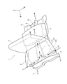
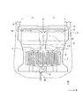
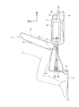
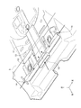
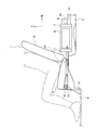
次に、本発明の車両用バッテリパック冷却構造の実施形態について図面を参照しながら説明する。図1は、本実施形態の車両用バッテリパック冷却構造の一実施形態を示す斜視図、図2は、図1の車両用バッテリパック冷却構造の平面図、図3は、図1の車両用バッテリパック冷却構造の側面図、図4は、図1の車両用バッテリパック冷却構造の正面図、図5は、図1の車両用バッテリパック冷却構造の吸気ダクトの斜視図である。本実施形態の車両は、前後2列の座席、即ちシート列を備える電気自動車又はハイブリッド自動車である。後席に相当するリヤシート1は、乗員が着席するシートクッション2と、乗員の背もたれとなるシートバック3を備えて構成される。図1〜図4に示すリヤシート1は、乗員が2〜3人着席できるように、車両幅方向に長手である。
Next, an embodiment of a vehicle battery pack cooling structure of the present invention will be described with reference to the drawings. 1 is a perspective view showing an embodiment of a vehicle battery pack cooling structure of the present embodiment, FIG. 2 is a plan view of the vehicle battery pack cooling structure of FIG. 1, and FIG. 3 is a vehicle battery of FIG. 4 is a side view of the pack cooling structure, FIG. 4 is a front view of the vehicle battery pack cooling structure of FIG. 1, and FIG. 5 is a perspective view of the intake duct of the vehicle battery pack cooling structure of FIG. The vehicle of the present embodiment is an electric vehicle or a hybrid vehicle having two rows of front and rear seats, that is, a seat row. A
前記リヤシート1のシートバック3より車両前方が車室で、リヤシート1のシートバック3より車両後方は、一般にラゲッジルームと呼ばれる荷室である。車室の下面は、フロントフロアパネル4によって床面が構成され、荷室の下面は、リヤフロアパネル5によって底面(床面)が形成されている。本実施形態のフロントフロアパネル4とリヤフロアパネル5は一連であり、両者の連結部分に、リヤフロアパネル5側が高くなる段差部6が形成され、この段差部6の上にリヤシート1のシートクッション2が配置される。本実施形態では、リヤシート1の車両後方のリヤフロアパネル5の上面にバッテリパック7が配置される。このバッテリパック7内には、多数のセルから構成されるバッテリモジュール8が複数収納され、夫々のバッテリモジュール8に電力が蓄積され、また蓄積された電力が放出される。なお、図5では、バッテリパックを省略している。また、荷室では、一般にトノカバーと呼ばれる目隠し用カバーでリヤフロアパネル5上を覆うこともある。
A front of the vehicle from the
バッテリパック7の内部は、車両後方向きに突出配置された排気ダクト9を介して冷却ファン10に接続されている。冷却ファン10を駆動すると、後述する吸気ダクトから車室内の空気が取入れられ、バッテリパック7の内部のバッテリモジュール8を冷却することができる。一方、バッテリパック7の車両幅方向中央部には、バッテリパック7の内部に通じる下流側吸気ダクト部11が接続されている。この下流側吸気ダクト部11は、リヤシート1のシートクッション2とリヤフロアパネル5との間で、車両前方に向けて長手に配置されている。そして、下流側吸気ダクト部11の車両前方端部には、当該下流側吸気ダクト部11の長手方向と交差する方向、つまり車両幅方向に長手な上流側吸気ダクト部12が接続され、この上流側吸気ダクト部12と下流側吸気ダクト部11とでバッテリパック7を冷却する空気の吸気ダクト13が構成されている。この吸気ダクト13を構成する上流側吸気ダクト部12及び下流側吸気ダクト部11は、夫々、リヤシート1のシートクッション2の下面に形成された凹溝内に収納されている。また、特に上流側吸気ダクト部12は、リヤシート1のシートクッション2下のクロスメンバとして機能するなど、吸気ダクト13全体でリヤシート1のシートクッション2の強度部材としても機能する。
The interior of the
本実施形態では、車両幅方向に長手な上流側吸気ダクト部12の車両幅方向両端部に、車室内の空気を取入れる空気取入口14を開設している。この空気取入口14は、リヤシート1のシートクッション2の下方で、車室内の左右のリヤドアの近傍、つまり車室の車両幅方向両端部に開口しており、そこから車室内の空気を取入れてバッテリパック7の内部に吸入する。また、下流側吸気ダクト部11と上流側吸気ダクト部12との接続部は、車両幅方向に長手な上流側吸気ダクト部12の車両幅方向中央部に位置するように構成している。そのため、図2に示すように、下流側吸気ダクト部11から車両右側の空気取入口14までの車両幅方向距離L1と、下流側吸気ダクト部11から車両左側の空気取入口14までの車両幅方向距離L2は同等又は略同等である。
In the present embodiment,
車両の車室内では、周知のように、日照の方向や日照状態によって空気の温度に偏りが生じる。この車室内空気の温度の偏りは、日照が差し込む、差し込まないなどから、車両前後方向と共に車両幅方向に大きく生じる。例えば、バッテリパックの内部を冷却するための空気を車室内から取入れるに際し、空気取入口が車両幅方向の何れか一方にだけ開口している場合には、日照によって温度が過度に上昇した空気を取入れる可能性があり、そのような場合には、バッテリパックの内部の冷却性能が低下する。これに対し、本実施形態の車両用バッテリパック冷却構造では、リヤシート1のシートクッション2の下方において、車室内の車両幅方向両側からバッテリパック7の内部を冷却するための空気を取入れる。そのため、車両幅方向の一方の車室内空気の温度が高い場合であっても、車両幅方向の他方の低い温度の車室内空気を取入れることにより、下流側吸気ダクト部11からバッテリパック7の内部に過度に高い温度の空気が吸入されるのを防止することができる。更には、下流側吸気ダクト部11から車両右側の空気取入口14までの距離L1と車両左側の空気取入口14までの距離L2を等しくすることにより、車両幅方向何れか一方の温度上昇した車室内空気と車両幅方向何れか他方の低温の車室内空気を均等に混合することができる。
As is well known, in the vehicle interior of a vehicle, the air temperature is biased depending on the direction of sunlight and the state of sunlight. The temperature deviation of the passenger compartment air greatly occurs in the vehicle width direction as well as in the vehicle front-rear direction because sunlight is inserted or not. For example, when air for cooling the inside of the battery pack is taken in from the passenger compartment, if the air intake is open only in one of the vehicle width directions, the air whose temperature has excessively increased due to sunlight In such a case, the cooling performance inside the battery pack is deteriorated. On the other hand, in the vehicle battery pack cooling structure of the present embodiment, air for cooling the inside of the
このように本実施形態の車両用バッテリパック冷却構造では、リヤシート1の車両後方でリヤフロアパネル5の上面に配置され、内部にバッテリモジュール8が収納されたバッテリパック7を冷却するに際し、バッテリパック7に接続された下流側吸気ダクト部11をリヤフロアパネル5の上面とリヤシート1のシートクッション2との間で車両前方に向けて配置し、その車両前端部に接続される上流側吸気ダクト部12をリヤフロアパネル5の上面とリヤシート1のシートクッション2との間で車両幅方向に向けて長手に配置し、上流側吸気ダクト部12の車両幅方向両端部に車室内の空気を取入れる空気取入口14を形成した。車室内での空気の温度上昇は、例えば日射の方向や日射状態によって車両幅方向で差異が生じる。これに対し、リヤシート1のシートクッション2の下方の上流側吸気ダクト部12の車両幅方向両端部に形成された空気取入口14から同時に車室内の空気を取入れる。そのため、乗員の脚部などで空気取入口を遮られることなく、車室内の車両幅方向両端部の空気を吸い込んで下流側吸気ダクト部11で合流させる。従って、車室内の車両幅方向で空気の温度差が生じていても、下流側吸気ダクト部11で合流された空気は温度が平均化される。即ち、過度に温度上昇した空気がバッテリパック7の内部へ吸入されるのを防止し、バッテリパック7内部の冷却性能を向上することができる。
As described above, in the vehicle battery pack cooling structure of the present embodiment, when cooling the
また、上流側吸気ダクト部12と下流側吸気ダクト部11との接続部を上流側吸気ダクト部12の車両幅方向中央部に配置した。そのため、車室内の車両幅方向両側で空気の温度差が生じていても、温度上昇した空気と低温な空気とを同量ずつ均等に混合することができ、過度に温度上昇した空気がバッテリパック7の内部へ吸入されるのを確実に防止することができる。
Further, the connecting portion between the upstream side
図6、図7は、本実施形態の車両用バッテリパック冷却構造の変形例であり、図6は、吸気ダクト13の斜視図、図7は吸気ダクト13の側面図である。なお、前記実施形態と同等の構成には同等の符号を付して、その詳細な説明を省略する。この変形例では、下流側吸気ダクト部11を上流側吸気ダクト部12内に貫通させて、更に車両前方(リヤシート1のシートクッション2の車両前方端部)まで延長し、その延長した車両前方端部に車両前方向きに開口する中央空気取入口15を形成した。下流側吸気ダクト部11と上流側吸気ダクト部12は、貫通部において、互いに内部が連結されている。この変形例によれば、前記実施形態に加え、更に車両幅方向中央部の車室内空気もバッテリパック7の内部冷却用空気として取入れて混合することができるため、バッテリパック7内部の冷却用空気温度をより一層均一化することが可能となる。
6 and 7 are modified examples of the vehicle battery pack cooling structure of the present embodiment, FIG. 6 is a perspective view of the
1 リヤシート
2 シートクッション
3 シートバック
4 フロントフロアパネル
5 リヤフロアパネル
6 段差部
7 バッテリパック
8 バッテリモジュール
9 排気ダクト
10 冷却ファン
11 下流側吸気ダクト部
12 上流側吸気ダクト部
13 吸気ダクト
14 空気取入口
15 中央空気取入口
DESCRIPTION OF
Claims (2)
前記リヤフロアパネルの上面と前記リヤシートのシートクッションとの間で前記バッテリパックから車両前方に向けて配置された下流側吸気ダクト部と、
前記下流側吸気ダクト部の車両前端部で当該下流側吸気ダクト部に接続され、前記リヤフロアパネルの上面と前記リヤシートのシートクッションとの間で車両幅方向に向けて長手に配置された上流側吸気ダクト部と、
前記上流側吸気ダクト部の車両幅方向両端部に形成され、車室内の空気を取入れる空気取入口とを備えたことを特徴とする車両用バッテリパック冷却構造。 In the vehicle battery pack cooling structure for cooling the battery pack that is disposed on the upper surface of the rear floor panel behind the rear seat and that houses the battery module,
A downstream intake duct portion disposed from the battery pack toward the front of the vehicle between an upper surface of the rear floor panel and a seat cushion of the rear seat;
Upstream intake air that is connected to the downstream intake duct portion at the vehicle front end of the downstream intake duct portion and is disposed longitudinally in the vehicle width direction between the upper surface of the rear floor panel and the seat cushion of the rear seat. A duct section;
A battery pack cooling structure for a vehicle, comprising air intake ports formed at both ends of the upstream side intake duct portion in the vehicle width direction for taking in air in the vehicle compartment.
Priority Applications (4)
| Application Number | Priority Date | Filing Date | Title |
|---|---|---|---|
| JP2012260110A JP2014104891A (en) | 2012-11-28 | 2012-11-28 | Cooling structure of vehicular battery pack |
| IN4743CH2013 IN2013CH04743A (en) | 2012-11-28 | 2013-10-22 | |
| CN201310560056.8A CN103855442B (en) | 2012-11-28 | 2013-11-12 | Battery pack cooling structure for motor car |
| DE201310223667 DE102013223667A1 (en) | 2012-11-28 | 2013-11-20 | Battery pack cooling structure for motor car, has air intake openings introducing air inside vehicle cabin that is formed at end portions along vehicle width direction of input air intake line portion |
Applications Claiming Priority (1)
| Application Number | Priority Date | Filing Date | Title |
|---|---|---|---|
| JP2012260110A JP2014104891A (en) | 2012-11-28 | 2012-11-28 | Cooling structure of vehicular battery pack |
Publications (1)
| Publication Number | Publication Date |
|---|---|
| JP2014104891A true JP2014104891A (en) | 2014-06-09 |
Family
ID=50679199
Family Applications (1)
| Application Number | Title | Priority Date | Filing Date |
|---|---|---|---|
| JP2012260110A Pending JP2014104891A (en) | 2012-11-28 | 2012-11-28 | Cooling structure of vehicular battery pack |
Country Status (4)
| Country | Link |
|---|---|
| JP (1) | JP2014104891A (en) |
| CN (1) | CN103855442B (en) |
| DE (1) | DE102013223667A1 (en) |
| IN (1) | IN2013CH04743A (en) |
Cited By (6)
| Publication number | Priority date | Publication date | Assignee | Title |
|---|---|---|---|---|
| JP2018129179A (en) * | 2017-02-08 | 2018-08-16 | 株式会社デンソー | Power supply device and working machine |
| JP2019104321A (en) * | 2017-12-11 | 2019-06-27 | トヨタ自動車株式会社 | Cooling duct |
| JP2020043663A (en) * | 2018-09-10 | 2020-03-19 | 株式会社Subaru | Cooling control device of storage battery, and electric vehicle |
| CN113363613A (en) * | 2021-06-01 | 2021-09-07 | 安徽五行动力新能源有限公司 | Lithium battery heat dissipation device capable of achieving graded adjustment and cooling and graded adjustment method thereof |
| WO2021240803A1 (en) * | 2020-05-29 | 2021-12-02 | 日産自動車株式会社 | Structure for discharging battery-cooling air |
| US20220320630A1 (en) * | 2021-03-30 | 2022-10-06 | Honda Motor Co., Ltd. | Electric vehicle |
Families Citing this family (2)
| Publication number | Priority date | Publication date | Assignee | Title |
|---|---|---|---|---|
| KR101655209B1 (en) * | 2015-06-15 | 2016-09-07 | 현대자동차 주식회사 | Cooling structure of seat and electronic module |
| US10608303B2 (en) * | 2017-02-08 | 2020-03-31 | Denso Corporation | Power source apparatus and work machine having the same |
Family Cites Families (4)
| Publication number | Priority date | Publication date | Assignee | Title |
|---|---|---|---|---|
| JP4602164B2 (en) | 2005-06-02 | 2010-12-22 | 本田技研工業株式会社 | vehicle |
| JP2008044424A (en) * | 2006-08-11 | 2008-02-28 | Toyota Motor Corp | Secondary battery cooling structure |
| JP2008221988A (en) * | 2007-03-12 | 2008-09-25 | Toyota Motor Corp | Automobile |
| US9126477B2 (en) * | 2007-05-30 | 2015-09-08 | Ford Global Technologies, Llc | Ductless cooling system for a vehicle power storage unit |
-
2012
- 2012-11-28 JP JP2012260110A patent/JP2014104891A/en active Pending
-
2013
- 2013-10-22 IN IN4743CH2013 patent/IN2013CH04743A/en unknown
- 2013-11-12 CN CN201310560056.8A patent/CN103855442B/en active Active
- 2013-11-20 DE DE201310223667 patent/DE102013223667A1/en active Pending
Cited By (8)
| Publication number | Priority date | Publication date | Assignee | Title |
|---|---|---|---|---|
| JP2018129179A (en) * | 2017-02-08 | 2018-08-16 | 株式会社デンソー | Power supply device and working machine |
| JP2019104321A (en) * | 2017-12-11 | 2019-06-27 | トヨタ自動車株式会社 | Cooling duct |
| JP2020043663A (en) * | 2018-09-10 | 2020-03-19 | 株式会社Subaru | Cooling control device of storage battery, and electric vehicle |
| JP7206079B2 (en) | 2018-09-10 | 2023-01-17 | 株式会社Subaru | Storage battery cooling control device and electric vehicle |
| WO2021240803A1 (en) * | 2020-05-29 | 2021-12-02 | 日産自動車株式会社 | Structure for discharging battery-cooling air |
| JP7448001B2 (en) | 2020-05-29 | 2024-03-12 | 日産自動車株式会社 | Battery cooling air exhaust structure |
| US20220320630A1 (en) * | 2021-03-30 | 2022-10-06 | Honda Motor Co., Ltd. | Electric vehicle |
| CN113363613A (en) * | 2021-06-01 | 2021-09-07 | 安徽五行动力新能源有限公司 | Lithium battery heat dissipation device capable of achieving graded adjustment and cooling and graded adjustment method thereof |
Also Published As
| Publication number | Publication date |
|---|---|
| DE102013223667A1 (en) | 2014-05-28 |
| CN103855442A (en) | 2014-06-11 |
| IN2013CH04743A (en) | 2015-07-31 |
| CN103855442B (en) | 2017-01-11 |
Similar Documents
| Publication | Publication Date | Title |
|---|---|---|
| JP2014104891A (en) | Cooling structure of vehicular battery pack | |
| JP6303030B2 (en) | Vehicle battery cooling structure | |
| CN103764424B (en) | Vehicle and be equipped on the cooling construction of supply unit of vehicle | |
| US10272796B2 (en) | Cooling structure for battery pack | |
| JP5277362B1 (en) | In-vehicle structure of battery pack | |
| US8042637B2 (en) | Vehicle-mounted battery cooling structure | |
| JP5023509B2 (en) | Power supply | |
| JP5198003B2 (en) | Battery pack structure | |
| JP6244391B2 (en) | vehicle | |
| US20100071980A1 (en) | Electric power storage apparatus and car | |
| US20120312610A1 (en) | Battery cooling structure for electric vehicle | |
| JP2009012606A (en) | Cooling structure for battery | |
| US9302573B2 (en) | Duct for high voltage battery air cooling exhaust and recirculation | |
| JP4631177B2 (en) | Vehicle battery cooling system | |
| US20150060167A1 (en) | Duct to influence air cooling distribution to battery module and dc/dc module | |
| JP2010198971A (en) | Battery pack | |
| AU2012261587B2 (en) | Vehicle | |
| JP6693282B2 (en) | Battery pack | |
| JP2003300419A (en) | Battery mounting structure for vehicle | |
| JP2005205953A (en) | Cooling device of electric appliance | |
| JP2014054864A (en) | Cooling structure of power storage device | |
| JP2014084044A (en) | Power device for vehicle | |
| JP2008117708A (en) | Battery pack structure | |
| JP4978050B2 (en) | Electricity storage pack | |
| JP4120484B2 (en) | Battery pack cooling structure and floorboard |