JP2014091237A - Heat transfer device and heat transfer method - Google Patents
Heat transfer device and heat transfer method Download PDFInfo
- Publication number
- JP2014091237A JP2014091237A JP2012241932A JP2012241932A JP2014091237A JP 2014091237 A JP2014091237 A JP 2014091237A JP 2012241932 A JP2012241932 A JP 2012241932A JP 2012241932 A JP2012241932 A JP 2012241932A JP 2014091237 A JP2014091237 A JP 2014091237A
- Authority
- JP
- Japan
- Prior art keywords
- transfer sheet
- sheet
- decorated
- transfer
- gripping
- Prior art date
- Legal status (The legal status is an assumption and is not a legal conclusion. Google has not performed a legal analysis and makes no representation as to the accuracy of the status listed.)
- Granted
Links
Images


Landscapes
- Electronic Switches (AREA)
- Thermal Transfer Or Thermal Recording In General (AREA)
- Registering, Tensioning, Guiding Webs, And Rollers Therefor (AREA)
- Handling Of Sheets (AREA)
- Handling Of Continuous Sheets Of Paper (AREA)
Abstract
【課題】高い位置精度で被加飾体への模様付けを行うことができるとともに、皺の発生や気泡の残留を抑制することができる熱転写装置を提供する。
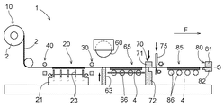
【解決手段】本発明は、ロール状の転写シート2の端部2eを引き出して被加飾体3に供給し、被加飾体3への模様の熱転写を連続的に行う熱転写装置1に関する。熱転写装置1は、被加飾体3を載置する載置部20と、載置部20の下流側に設けられ、転写シート2を把持した状態でシート送り方向F及び幅方向に移動可能な第一把持部30と、載置部20の上流側に設けられ、転写シート2を把持した状態で幅方向に移動可能な第二把持部40と、これらを昇降可能に支持する支持部50と、を備える。
【選択図】図1There is provided a thermal transfer apparatus capable of patterning an object to be decorated with high positional accuracy and suppressing generation of wrinkles and residual bubbles.
The present invention relates to a thermal transfer apparatus 1 that pulls out an end 2e of a roll-shaped transfer sheet 2 and supplies it to a body to be decorated 3 to continuously transfer a pattern to the body 3 to be decorated. The thermal transfer device 1 is provided on the downstream side of the placement unit 20 on which the object to be decorated 3 is placed, and is movable in the sheet feeding direction F and the width direction while holding the transfer sheet 2. A first grip 30; a second grip 40 provided on the upstream side of the placement unit 20 and capable of moving in the width direction while gripping the transfer sheet 2; .
[Selection] Figure 1
Description
本発明は、ロール状に保持された転写シートの端部を引き出し、被加飾体に対して転写シートを供給して加熱し、被加飾体への模様の転写を連続的に行う熱転写装置及び熱転写方法に関する。 The present invention relates to a thermal transfer apparatus that pulls out an end portion of a transfer sheet held in a roll shape, supplies the transfer sheet to the object to be decorated, heats it, and continuously transfers the pattern to the object to be decorated And a thermal transfer method.
上記のような熱転写装置として、特開2002−104350号公報(特許文献1)に記載された装置が知られている。この装置は、平面視で重なるように転写加圧部〔加圧ローラ11〕、転写層を有する転写シート〔転写フィルム6〕、及び被加飾体〔アルミ材1〕を配置した状態で、転写加圧部により被加飾体の表面に転写シートを押し付ける。そして、転写加圧部の熱と圧力とによって、転写シートの転写層を被加飾体に転写する。転写後、転写層が剥離された状態の転写シートは巻き取りローラによって回収される。この一連の工程を連続的に行うことにより、被加飾体への模様の転写を連続的に行っている。 As such a thermal transfer apparatus, an apparatus described in JP-A-2002-104350 (Patent Document 1) is known. In this apparatus, a transfer pressure unit [pressure roller 11], a transfer sheet [transfer film 6] having a transfer layer, and a decoration object [aluminum material 1] are arranged so as to overlap in plan view. The transfer sheet is pressed against the surface of the object to be decorated by the pressure unit. And the transfer layer of a transfer sheet is transcribe | transferred to a to-be-decorated body with the heat and pressure of a transfer pressurization part. After the transfer, the transfer sheet with the transfer layer peeled off is collected by a take-up roller. By continuously performing this series of steps, the pattern is continuously transferred to the object to be decorated.
特許文献1の装置では、ガイドローラで案内された転写シートは、被加飾体の近傍において当該被加飾体に対向するように供給される。この状態で転写加圧部を駆動させて、被加飾体の表面に転写シートを接触させるのと同時に加圧する。このため、転写加圧部の下方にそれぞれ供給される転写シート又は被加飾体に位置ずれ等が生じていたとしても、これらの当初の位置関係が保持されたまま、転写層が被加飾体に転写される。その結果、被加飾体における所望の位置に適切に模様付けを行うことができない可能性があった。また、被加飾体の表面への転写シートの接触とこれらの加圧とが同時に行われる際に、被加飾体に対して転写シートが不十分に沿った形態となり、その結果、転写層に皺が発生したり被加飾体と転写層との間に気泡が残留したりする可能性があった。
In the apparatus of
そこで、高い位置精度で被加飾体への模様付けを行うことができるとともに、皺の発生や気泡の残留を抑制することができる熱転写装置及び熱転写方法の実現が望まれる。 Therefore, it is desired to realize a thermal transfer device and a thermal transfer method that can perform patterning on the object to be decorated with high positional accuracy and can suppress generation of wrinkles and residual bubbles.
本発明に係る、ロール状に保持された転写シートの端部を引き出し、被加飾体に対して前記転写シートを供給して加熱し、前記被加飾体への模様の転写を連続的に行う熱転写装置の特徴構成は、平面視で前記転写シートと重なる位置に前記被加飾体を載置可能な載置部と、前記載置部に対してシート送り方向の下流側に設けられ、前記転写シートを把持可能であり、かつ、前記シート送り方向及び当該シート送り方向に直交する幅方向に移動可能な第一把持部と、前記載置部に対して前記シート送り方向の上流側に設けられ、前記転写シートを把持可能であり、かつ、少なくとも前記幅方向に移動可能な第二把持部と、前記第一把持部及び前記第二把持部をそれぞれ昇降可能に支持する支持部と、を備える点にある。 According to the present invention, the end of the transfer sheet held in a roll shape is pulled out, and the transfer sheet is supplied to the object to be decorated and heated to continuously transfer the pattern to the object to be decorated. The characteristic configuration of the thermal transfer device to be performed is provided on the downstream side in the sheet feeding direction with respect to the placement portion, the placement portion on which the object to be decorated can be placed at a position overlapping the transfer sheet in plan view, A first gripping portion capable of gripping the transfer sheet and movable in the sheet feeding direction and a width direction orthogonal to the sheet feeding direction; and upstream of the placement portion in the sheet feeding direction. A second gripping portion that is provided and capable of gripping the transfer sheet and is movable at least in the width direction; and a support portion that supports the first gripping portion and the second gripping portion so as to be movable up and down. It is in the point provided with.
この特徴構成によれば、被加飾体と平面視で重なるように転写シートが供給された状態で、載置部の下流側において第一把持部により転写シートを把持して、被加飾体に対する転写シートのシート送り方向及び幅方向の位置を調整することができる。また、被加飾体と平面視で重なるように転写シートが供給された状態で、載置部の上流側において第二把持部により転写シートを把持して、被加飾体に対する転写シートの少なくとも幅方向の位置を調整することができる。よって、転写前に、被加飾体に対する転写シートのシート送り方向に沿った位置及び向きを適正化することができる。従って、高い位置精度で被加飾体への模様付けを行うことができる。
また、上記の特徴構成によれば、被加飾体に対する転写シートの位置関係が適正化された状態で、転写シートをそれぞれ把持した第一把持部及び第二把持部を下降させることができる。よって、転写前に、被加飾体と転写シートとを全面的に接触させることができる。従って、被加飾体に対して転写シートが十分に沿った状態で熱転写を行うことができ、皺の発生や気泡の残留を抑制することができる。さらに、被加飾体と転写シートとを全面的に接触させることによって転写シートの伸びムラがなくなるので、被加飾体への模様付けの位置精度をさらに高めることができる。
According to this characteristic configuration, the transfer sheet is gripped by the first gripping portion on the downstream side of the placement portion in a state where the transfer sheet is supplied so as to overlap with the decorating body in plan view, The position of the transfer sheet relative to the sheet in the sheet feeding direction and the width direction can be adjusted. In addition, in a state where the transfer sheet is supplied so as to overlap with the object to be decorated in plan view, at least the transfer sheet with respect to the object to be decorated is gripped by the second gripping part on the upstream side of the placing part. The position in the width direction can be adjusted. Therefore, the position and direction along the sheet feeding direction of the transfer sheet relative to the object to be decorated can be optimized before transfer. Therefore, it is possible to pattern the object to be decorated with high positional accuracy.
Moreover, according to said characteristic structure, the 1st holding part and the 2nd holding part which each hold | gripped the transfer sheet can be lowered | hung in the state in which the positional relationship of the transfer sheet with respect to the to-be-decorated object was optimized. Therefore, the object to be decorated and the transfer sheet can be brought into full contact before transfer. Therefore, thermal transfer can be performed with the transfer sheet sufficiently along the object to be decorated, and generation of wrinkles and residual bubbles can be suppressed. Furthermore, since the unevenness of the transfer sheet is eliminated by bringing the object to be decorated and the transfer sheet into contact with each other, the positional accuracy of patterning on the object to be decorated can be further increased.
ここで、少なくとも前記第一把持部、前記第二把持部、及び前記支持部の動作制御を行う制御部を備え、前記被加飾体が平面視で前記転写シートと重なるように前記載置部に載置された状態で、前記制御部は、前記第一把持部により、前記転写シートの第一部分を把持して当該転写シートの前記シート送り方向の位置及び前記幅方向の位置を調整させ、その後、前記第二把持部により、前記転写シートの第二部分を把持して当該転写シートの前記幅方向の位置を調整させ、その後、前記第一部分が前記第二部分よりも下方に位置する状態で、前記第一把持部及び前記第二把持部を下降させると好適である。 Here, at least the first gripping unit, the second gripping unit, and a control unit that controls the operation of the support unit, the mounting unit described above so that the object to be decorated overlaps the transfer sheet in plan view The controller is configured to hold the first portion of the transfer sheet by the first gripping unit and adjust the position in the sheet feeding direction and the position in the width direction of the transfer sheet, After that, the second gripping portion grips the second portion of the transfer sheet to adjust the position of the transfer sheet in the width direction, and then the first portion is positioned below the second portion. Thus, it is preferable that the first gripping portion and the second gripping portion are lowered.
この構成によれば、載置部の上流側における転写シートの位置調整が行われるよりも前に、下流側における位置調整が行われる。シート送り方向の最上流側には転写シートがロール状に保持されており、このロール状部分は、引き出される転写シートに対して逆張力(バックテンション)を作用させる。この逆張力を利用して、転写シートに作用する張力を維持させたまま、転写シートの第一部分の位置調整を行うことができる。
この場合、第一部分の位置調整の完了時には、転写シートの第二部分のシート送り方向の位置も既に調整されている。このため、第二部分については、幅方向の位置を積極的に調整するだけで、シート送り方向の位置及び幅方向の位置の双方を調整することができる。よって、第二把持部をシート送り方向には移動可能とする必要性がなくなるので、第二把持部を移動可能とするための駆動機構の構成を簡素化できる。
また、第一把持部及び第二把持部を下降させる際には、転写シートの第一部分が第二部分よりも下方に位置する状態で下降させる。これにより、転写シートを下流側から上流側に向かって徐々に被加飾体に接触させることができ、接触領域の中央部での空気の残留を抑制することができる。よって、皺の発生や気泡の残留を有効に抑制できる。
According to this configuration, the position adjustment on the downstream side is performed before the position adjustment of the transfer sheet on the upstream side of the placing portion is performed. The transfer sheet is held in a roll shape on the most upstream side in the sheet feeding direction, and this roll-shaped portion applies reverse tension (back tension) to the drawn transfer sheet. Using this reverse tension, the position of the first portion of the transfer sheet can be adjusted while maintaining the tension acting on the transfer sheet.
In this case, when the position adjustment of the first portion is completed, the position of the second portion of the transfer sheet in the sheet feeding direction has already been adjusted. For this reason, it is possible to adjust both the position in the sheet feeding direction and the position in the width direction by positively adjusting the position in the width direction for the second portion. Accordingly, it is not necessary to make the second gripping part movable in the sheet feeding direction, and the configuration of the drive mechanism for making the second gripping part movable can be simplified.
Further, when the first grip portion and the second grip portion are lowered, the first portion of the transfer sheet is lowered in a state where the first portion is positioned below the second portion. Thereby, a transfer sheet can be made to contact a to-be-decorated body gradually toward the upstream from the downstream, and the residual of the air in the center part of a contact area | region can be suppressed. Therefore, generation | occurrence | production of a soot and a bubble remaining can be suppressed effectively.
また、前記載置部は、一方端が当該載置部の載置面に開口するとともに他方端が吸引装置に接続された吸引孔を有し、前記吸引装置は、前記被加飾体に対して前記転写シートが全面的に接触した状態で吸引動作を行うと好適である。 In addition, the placement unit has a suction hole with one end opening on the placement surface of the placement unit and the other end connected to a suction device, and the suction device is connected to the object to be decorated. It is preferable to perform the suction operation with the transfer sheet in contact with the entire surface.
この構成によれば、吸引装置を動作させることで、被加飾体に対する転写シートの位置関係が適正化され、かつ、被加飾体と転写シートとが全面的に接触した状態を、適切に維持できる。よって、被加飾体の所望の位置に、皺や気泡を残すことなく適切に模様付けを行うことができる。 According to this configuration, by operating the suction device, the positional relationship of the transfer sheet with respect to the object to be decorated is optimized, and the state in which the object to be decorated and the transfer sheet are in full contact with each other is appropriately Can be maintained. Therefore, a pattern can be appropriately formed without leaving a wrinkle or a bubble at a desired position of the object to be decorated.
また、前記載置部が、当該載置部の前記シート送り方向の上流側端部及び下流側端部における前記転写シートに対向する位置に、前記幅方向に沿って側面から見た場合に曲線状となる曲面部を有すると好適である。 Further, when the placement unit is viewed from the side along the width direction at a position facing the transfer sheet at the upstream end and the downstream end in the sheet feeding direction of the placement unit, a curve is obtained. It is preferable to have a curved surface portion.
第一把持部及び第二把持部を下降させて転写シートを被加飾体に接触させる場合には、転写シートにおける第一把持部や第二把持部で把持された部分が、載置部の上面よりも下方まで下降する場合がある。この場合、載置部のシート送り方向の両側の端縁部と転写シートとが擦れ合って、転写シートに傷がついたり、その一部が剥離していわゆる箔チリが発生したりする可能性がある。
そこで上記の構成のように、載置部がその上流側端部及び下流側端部に転写シートに対向する曲面部を有する構成とすることで、載置部と転写シートとを、載置部の曲面部に沿って滑らかに面接触させることができる。よって、転写シートの損傷や箔チリの発生を有効に抑制することができる。
When lowering the first gripping part and the second gripping part to bring the transfer sheet into contact with the object to be decorated, the portion gripped by the first gripping part or the second gripping part of the transfer sheet There is a case where it descends below the upper surface. In this case, the transfer sheet may rub against the edge of both sides of the loading section in the sheet feeding direction, and the transfer sheet may be scratched, or a part of the transfer sheet may be peeled off to generate so-called foil dust. There is.
Therefore, as in the configuration described above, the placement portion has a curved surface portion facing the transfer sheet at the upstream end portion and the downstream end portion thereof, so that the placement portion and the transfer sheet are placed on the placement portion. The surface can be smoothly contacted along the curved surface portion. Therefore, damage to the transfer sheet and generation of foil dust can be effectively suppressed.
また、前記載置部は、平面視で矩形状に形成されるとともに前記上流側端部及び前記下流側端部の辺部に沿って形成される切欠状溝部を有する載置台と、前記切欠状溝部に配置される円筒状部材とを備え、前記曲面部が、前記円筒状部材の表面により構成されていると好適である。 Further, the mounting portion is formed in a rectangular shape in plan view and has a mounting table having a notched groove portion formed along a side portion of the upstream end portion and the downstream end portion, and the cutout shape. It is preferable that a cylindrical member disposed in the groove portion is provided, and the curved surface portion is constituted by a surface of the cylindrical member.
この構成によれば、矩形状の載置台の対向する辺部に沿って切欠状溝部を形成するとともに、その切欠状溝部に円筒状部材を配置することで、円筒状部材の表面を利用した簡素な構成で、一対の曲面部を有する載置部を実現できる。 According to this structure, while forming the notch-shaped groove part along the opposing side part of a rectangular mounting base, and arrange | positioning a cylindrical member in the notch-shaped groove part, the simple using the surface of the cylindrical member With this configuration, a mounting portion having a pair of curved surface portions can be realized.
また、冷媒を流通させる冷媒流通経路を備え、前記冷媒流通経路が、前記円筒状部材の内周空間を通るように構成されていると好適である。 In addition, it is preferable that a refrigerant flow path for flowing the refrigerant is provided, and the refrigerant flow path is configured to pass through an inner circumferential space of the cylindrical member.
熱転写を行う際には、被加飾体を加熱するべく載置台が高温状態とされる場合がある。この場合、その熱によって載置台と転写シートとが融着してしまう可能性がある。
この構成によれば、円筒状部材の内周空間を流通する冷媒との間の熱交換により、曲面部に沿って接触している転写シートの部分を冷却することができる。よって、当該部分において、載置台と転写シートとが融着するのを抑制することができる。つまり、転写シートの損傷や箔チリの発生を抑制するための構成を有効利用して、載置台と転写シートとの融着をも抑制することができる。
When performing thermal transfer, the mounting table may be in a high temperature state to heat the object to be decorated. In this case, the mounting table and the transfer sheet may be fused by the heat.
According to this configuration, the portion of the transfer sheet that is in contact with the curved surface portion can be cooled by heat exchange with the refrigerant flowing through the inner circumferential space of the cylindrical member. Therefore, in the said part, it can suppress that a mounting base and a transfer sheet fuse | melt. That is, it is possible to effectively suppress the fusion between the mounting table and the transfer sheet by effectively utilizing the configuration for suppressing damage to the transfer sheet and generation of foil dust.
また、前記第一把持部及び前記第二把持部は、それぞれ上側把持部と下側把持部とを有し、前記第一把持部及び前記第二把持部のそれぞれにおける上側把持部が、対をなす下側把持部に対向する位置に、前記幅方向に沿って側面から見た場合に曲線状となる曲面部を有すると好適である。 The first gripping part and the second gripping part each have an upper gripping part and a lower gripping part, and the upper gripping part in each of the first gripping part and the second gripping part is paired. It is preferable to have a curved surface portion that is curved when viewed from the side surface along the width direction at a position facing the lower gripping portion formed.
この構成によれば、第一把持部の上側把持部と転写シートとを、当該上側把持部の曲面部に沿って滑らかに接触させることができる。また、第二把持部の上側把持部と転写シートとを、当該上側把持部の曲面部に沿って滑らかに接触させることができる。よって、転写シートの損傷や箔チリの発生を有効に抑制することができる。 According to this configuration, the upper grip portion of the first grip portion and the transfer sheet can be smoothly contacted along the curved surface portion of the upper grip portion. In addition, the upper gripping portion of the second gripping portion and the transfer sheet can be smoothly contacted along the curved surface portion of the upper gripping portion. Therefore, damage to the transfer sheet and generation of foil dust can be effectively suppressed.
本発明に係る、ロール状に保持された転写シートの端部を引き出し、被加飾体に対して前記転写シートを供給して加熱し、前記被加飾体への模様の転写を連続的に行う熱転写方法の特徴構成は、引き出された前記転写シートと平面視で重なる位置に前記被加飾体を載置する載置工程と、前記載置工程の後、前記被加飾体に対してシート送り方向の下流側において、前記転写シートの第一部分を把持して、前記第一部分の前記シート送り方向の位置及び前記シート送り方向に直交する幅方向の位置を調整する第一調整工程と、前記第一調整工程の後、前記被加飾体に対して前記シート送り方向の上流側において、前記転写シートの第二部分を把持して、前記第二部分の前記幅方向の位置を調整する第二調整工程と、前記第二調整工程の後、前記転写シートが前記シート送り方向の下流側から上流側に向かって徐々に前記被加飾体に接触するように、前記転写シートの前記第一部分及び前記第二部分を下降させる下降工程と、を備える点にある。 According to the present invention, the end of the transfer sheet held in a roll shape is pulled out, and the transfer sheet is supplied to the object to be decorated and heated to continuously transfer the pattern to the object to be decorated. The characteristic configuration of the thermal transfer method to be performed is a placement step of placing the object to be decorated at a position overlapping the drawn-out transfer sheet in a plan view, and after the placement step, On the downstream side in the sheet feeding direction, a first adjustment step of gripping the first part of the transfer sheet and adjusting the position of the first part in the sheet feeding direction and the position in the width direction perpendicular to the sheet feeding direction; After the first adjustment step, the second portion of the transfer sheet is gripped on the upstream side in the sheet feeding direction with respect to the object to be decorated, and the position of the second portion in the width direction is adjusted. After the second adjustment step and the second adjustment step, A lowering step of lowering the first portion and the second portion of the transfer sheet so that the copy sheet gradually contacts the object to be decorated from the downstream side to the upstream side in the sheet feeding direction. In the point.
この特徴構成によれば、載置工程により転写シートと平面視で重なる位置に被加飾体が載置された状態で、第一調整工程により、被加飾体に対する転写シートの第一部分の、シート送り方向及び幅方向の位置を調整することができる。また、その状態で、第二調整工程により、被加飾体に対する転写シートの第二部分の、幅方向の位置を調整することができる。よって、転写前に、被加飾体に対する転写シートのシート送り方向に沿った位置及び向きを適正化することができる。従って、高い位置精度で被加飾体への模様付けを行うことができる。
このとき、第二調整工程により載置部の上流側における転写シートの位置調整が行われるよりも前に、第一調整工程により下流側における位置調整が行われる。シート送り方向の最上流側には転写シートがロール状に保持されており、このロール状部分は、引き出される転写シートに対して逆張力を作用させる。この逆張力を利用して転写シートに作用する張力を維持させたまま、転写シートの第一部分の位置調整を行うことができる。また、この場合、第一部分の位置調整の完了時には、転写シートの第二部分のシート送り方向の位置も既に調整されている。このため、第二調整工程では、第二部分の幅方向の位置を積極的に調整するだけで、シート送り方向の位置及び幅方向の位置の双方を調整することができる。よって、第二調整工程を簡素化できる。
また、上記の特徴構成によれば、被加飾体に対する転写シートの位置関係が適正化された状態で、下降工程により、転写シートの第一部分及び第二部分を下降させる。その際、下流側から上流側に向かって転写シートを徐々に被加飾体に接触させることで、転写前に、接触領域の中央部での空気の残留を抑制しつつ、被加飾体と転写シートとを全面的に接触させることができる。従って、被加飾体に対して転写シートが十分に沿った状態で熱転写を行うことができ、皺の発生や気泡の残留を有効に抑制することができる。さらに、被加飾体と転写シートとを全面的に接触させることによって転写シートの伸びムラがなくなるので、被加飾体への模様付けの位置精度をさらに高めることができる。
According to this characteristic configuration, in the state where the object to be decorated is placed at a position overlapping with the transfer sheet in plan view by the placing process, the first adjustment step of the first part of the transfer sheet with respect to the object to be decorated, The position in the sheet feeding direction and the width direction can be adjusted. Moreover, the position of the width direction of the 2nd part of the transfer sheet with respect to a to-be-decorated body can be adjusted by the 2nd adjustment process in the state. Therefore, the position and direction along the sheet feeding direction of the transfer sheet relative to the object to be decorated can be optimized before transfer. Therefore, it is possible to pattern the object to be decorated with high positional accuracy.
At this time, before the position adjustment of the transfer sheet on the upstream side of the placement portion is performed in the second adjustment step, the position adjustment on the downstream side is performed in the first adjustment step. The transfer sheet is held in a roll shape on the most upstream side in the sheet feeding direction, and this roll-shaped portion applies a reverse tension to the drawn transfer sheet. The position of the first portion of the transfer sheet can be adjusted while maintaining the tension acting on the transfer sheet using this reverse tension. In this case, when the position adjustment of the first part is completed, the position of the second part of the transfer sheet in the sheet feeding direction is already adjusted. For this reason, in the second adjustment step, both the position in the sheet feeding direction and the position in the width direction can be adjusted only by positively adjusting the position in the width direction of the second portion. Therefore, the second adjustment process can be simplified.
Moreover, according to said characteristic structure, in the state in which the positional relationship of the transfer sheet with respect to the to-be-decorated body was optimized, the 1st part and 2nd part of a transfer sheet are lowered | hung by a descent | fall process. At that time, by gradually bringing the transfer sheet into contact with the object to be decorated from the downstream side toward the upstream side, before the transfer, while suppressing the residual air in the center of the contact area, The transfer sheet can be brought into full contact with the transfer sheet. Therefore, thermal transfer can be performed with the transfer sheet sufficiently along the object to be decorated, and generation of wrinkles and residual bubbles can be effectively suppressed. Furthermore, since the unevenness of the transfer sheet is eliminated by bringing the object to be decorated and the transfer sheet into contact with each other, the positional accuracy of patterning on the object to be decorated can be further increased.
ここで、前記下降工程の後、前記被加飾体の下方から前記転写シートを吸引する吸引工程をさらに備えると好適である。 Here, after the descending step, it is preferable to further include a suction step of sucking the transfer sheet from below the decoration object.
この構成によれば、下降工程の後に吸引工程を実行することで、被加飾体に対する転写シートの位置関係が適正化され、かつ、被加飾体と転写シートとが全面的に接触した状態を、適切に維持できる。よって、被加飾体の所望の位置に、皺や気泡を残すことなく適切に模様付けを行うことができる。 According to this configuration, by performing the suction step after the descending step, the positional relationship of the transfer sheet with respect to the object to be decorated is optimized, and the object to be decorated and the transfer sheet are in full contact with each other Can be maintained appropriately. Therefore, a pattern can be appropriately formed without leaving a wrinkle or a bubble at a desired position of the object to be decorated.
また、前記下降工程において、前記転写シートの前記第二部分を把持した第二把持部を、前記転写シートの前記第一部分を把持した第一把持部に対して所定時間だけ遅延させて下降させると好適である。 Further, in the lowering step, the second gripping portion that grips the second portion of the transfer sheet is lowered with a predetermined time delay with respect to the first gripping portion that grips the first portion of the transfer sheet. Is preferred.
或いは、前記下降工程において、前記転写シートの前記第一部分を把持した第一把持部と前記転写シートの前記第二部分を把持した第二把持部とを、前記第一部分が前記第二部分よりも下方に位置する状態で一体的に下降させると好適である。 Alternatively, in the descending step, the first grip portion that grips the first portion of the transfer sheet and the second grip portion that grips the second portion of the transfer sheet, the first portion is more than the second portion. It is preferable to lower it integrally in a state of being located below.
これらの構成によれば、下降工程において転写シートの第一部分及び第二部分を下降させる際に、下流側から上流側に向かって転写シートを徐々に被加飾体に接触させる構成を適切に実現できる。 According to these configurations, when the first portion and the second portion of the transfer sheet are lowered in the descending step, a configuration in which the transfer sheet is gradually brought into contact with the object to be decorated from the downstream side toward the upstream side is appropriately realized. it can.
本発明に係る熱転写装置及び熱転写方法の実施形態について、図面を参照して説明する。本実施形態に係る熱転写装置1は、ロール状に保持された転写シート2の端部2eを引き出し、被加飾体3に対して転写シート2を供給して加熱し、被加飾体3への模様の転写を連続的に行うための装置である。本実施形態に係る熱転写装置1は、ロール式の熱転写装置として構成されている。以下、本実施形態に係る熱転写装置1の構成、及びこの熱転写装置1を用いて実行される熱転写方法の手順について詳細に説明する。
Embodiments of a thermal transfer apparatus and a thermal transfer method according to the present invention will be described with reference to the drawings. The
なお、本実施形態では、引き出される転写シート2が順次送られる方向を「シート送り方向F」と定義する。このシート送り方向Fは、転写シート2の長手方向に平行である。また、本実施形態では、「上流」及び「下流」の用語は、シート送り方向Fを基準として定義する。すなわち、シート送り方向Fに沿って、相対的にシート保持部10側(図1における左側)を「上流側」と表し、相対的に排出部85側(図1における右側)を「下流側」と表す。また、転写シート2に沿ってシート送り方向Fに直交する方向を「幅方向W」と定義する。
In the present embodiment, the direction in which the drawn
1.熱転写装置の全体構成
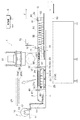
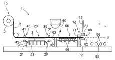
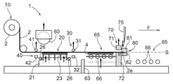
図1に示すように、熱転写装置1は、シート保持部10、載置部20、第一把持部30、第二把持部40、支持部50、及び転写加圧部60を備えている。また、熱転写装置1は、待機部65、固定狭持部70、切断部75、可動狭持部80、及び排出部85を備えている。さらに、熱転写装置1は、これら各部の動作制御を行う制御部6を備えている。シート保持部10、第二把持部40、載置部20、第一把持部30、待機部65、切断部75、及び排出部85は、シート送り方向Fに沿って記載の順に配置されている。
1. Overall Configuration of Thermal Transfer Device As shown in FIG. 1, the
支持部50は、第一把持部30及び第二把持部40を昇降可能に支持している。転写加圧部60は、載置部20に対してシート送り方向Fに相対移動可能に構成されている。固定狭持部70は、待機部65の下流側端部の位置に固定されている。可動狭持部80は、平面視で排出部85と重なる領域をシート送り方向Fに沿ってスライド可能に構成されている。これらの各部は、転写加圧部60を除き、シート送り方向Fに沿ってスライド可能に構成された転写テーブル90上に配置されている。
The
シート保持部10は、ロール巻きされた状態の転写シート2を保持している。シート保持部10は、転写テーブル90に固定された保持台11と、転写シート2の幅方向Wの両側において互いに対向するように保持台11に立設された保持板12と、対向する保持板12の間に架け渡された支軸13とを有する。転写シート2は、支軸13にロール巻きされた状態で保持されている。転写シート2は、シート送り方向Fの下流側の端部2eが可動狭持部80によって挟持されて引き出される(図14を参照)。引き出された転写シート2は、ガイドローラ14によって案内されて載置部20及び被加飾体3に供給される。なお、ガイドローラ14を粘着ロール等で構成して、案内機能に加えて埃除去機能を付与しても良い。
The
ガイドローラ14よりも下流側では、引き出された転写シート2は、載置部20の上面(載置台21の載置面21a)に対して上方に離間している。すなわち、転写テーブル90を基準とする転写シート2のシート高さは載置面21aの高さよりも高い。本実施形態では、このときの転写シート2の位置を「シート基準位置S」と定義する。
On the downstream side of the
図1に拡大して示すように、転写シート2は、基体シート2Aと、この基体シート2Aに形成された転写層2Bとを備えている。基体シート2Aは、長尺状のシート体であり、このシート体上に断続的に所定配列で形成される複数の転写層2Bを支持している。基体シート2Aは、ポリエステル系樹脂、ポリプロピレン系樹脂、アクリル系樹脂、ポリカーボネート系樹脂、ポリアミド系樹脂、ポリイミド系樹脂、オレフィン系樹脂、ウレタン系樹脂、及びアクリロニトリルブタジエンスチレン系樹脂等の合成樹脂を用いて構成することができる。これらの樹脂の共重合体や混合物を用いて構成しても良い。中でも、ポリエチレンテレフタレート等のポリエステル系樹脂は、形状安定性に優れており熱変形しにくいため、基体シート2Aを構成する材料として好適である。また、基体シート2Aは、単層シートとして構成しても良いし、複数の単層シートを積層してなる積層シートとして構成しても良い。
As shown in FIG. 1 in an enlarged manner, the
転写層2Bは、基体シート2A上に形成された図柄層2Baと、図柄層2Ba上に形成された接着層2Bbとを有する。図柄層2Baは、例えば着色インキや金属薄膜等を含み、文字や絵柄等を表現する。接着層2Bbは、加飾対象である被加飾体3の材質に応じた感熱性又は感圧性の樹脂層を含み、被加飾体3と図柄層2Baとの接着性を向上させる。なお、転写層2Bは、表面強度を向上させて耐擦傷性を付与するためのハードコート層や、層間密着性を向上させるためのアンカー層等をさらに有しても良い。さらに、基体シート2Aと転写層2Bとの間に、基体シート2Aからの転写層2Bの剥離性を向上させるための離型層が備えられても良い。これらの各層は、グラビア印刷法、スクリーン印刷法、及びオフセット印刷法等の印刷法や、グラビアコート法、ロールコート法、及びコンマコート法等のコート法等により形成することができる。
The transfer layer 2B has a design layer 2Ba formed on the
被加飾体3は、図柄層2Baを有する転写層2Bが転写されることによって加飾される対象となる部材である。本実施形態では、被加飾体3として金属体を用いる。例えば金属プレス板等を被加飾体3とすることができる。本例のように金属体を加飾対象とする場合には、前処理が施されたものを用いることが好ましい。このような前処理としては、プラズマ処理やフレーム処理等の表面処理が例示される。アルミニウムを主成分とする金属体の場合には、アルマイト処理であっても良い。また、前処理として、金属体の表面に接着剤や接着シート等による接着層を予め形成しておいても良い。なお、何の前処理も行われていない被加飾体3を用いることもできる。また、被加飾体3としてガラス板や樹脂板等を用いることも可能である。
The to-
熱転写装置1には、転写シート2のシート送り方向Fの位置を検出するセンサ(図示せず)と、幅方向Wの位置を検出するセンサ(図示せず)とが備えられている。これらのセンサは、基体シート2Aに施された、当該基体シート2Aの長手方向に沿った基準線(フローライン)や、転写層2Bの位置に応じて一定間隔で現れる基準点(アイマーク)を検出する。可動狭持部80による転写シート2の引き出し動作は、基体シート2A上の基準点が検出されると停止する。これにより、載置部20及び被加飾体3に対する転写シート2(ここでは特に、転写層2B)のおおよその位置合わせ(以下、「予備位置合わせ」と称する)をすることができる。
The
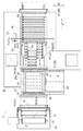
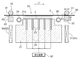
載置部20は、平面視で転写シート2と重なる位置に被加飾体3を載置可能に構成されている。図1及び図2に示すように、載置部20は、平面視で矩形状となる、直方体状に形成された載置台21を備えている。載置台21は、被加飾体3を載置する載置面21aを上面として有する。図2に示すように、載置台21は、幅方向Wに沿ってその下部に設けられたレール体22上をスライド可能に構成されている。これにより、載置台21は、平面視で転写シート2と重なる位置に配置された重複状態と、平面視で転写シート2と重なることなく幅方向Wの異なる位置に配置された非重複状態とをとり得る。非重複状態で被加飾体3を載置面21aに新たに載置した後、重複状態とすることで、平面視で転写シート2と重なる位置に被加飾体3が載置される(図7等も参照)。
The
載置台21は、その内部に埋設されたヒータ(図示せず)によって加熱されるホットプレートである。また、載置部20は、先端部が載置面21aから突出可能な複数のピン部材23を備えている。図2に示すように、複数のピン部材23は、平面視で、載置台21の略全面に亘って所定規則で配列されている。複数のピン部材23は、縦横にそれぞれ一定間隔で規則的に(本例では、直交格子状に)配列されている。図13及び図17等に示すように、ピン部材23は、その先端部が載置面21aの位置とシート基準位置Sとの間で突出引退可能に構成されている。
The mounting table 21 is a hot plate that is heated by a heater (not shown) embedded therein. Further, the mounting
載置台21とピン部材23とは、被加飾体3の載置状態を切替可能な載置状態切替機構Mとして機能する。載置状態切替機構Mは、当接載置状態と離間載置状態とを切替可能である。当接載置状態は、被加飾体3を載置面21aに当接させて配置させた状態である(図5を参照)。この当接載置状態は、載置面21aからピン部材23を引退させる(ピン部材23の先端部を載置面21aのレベルに一致させることを含む)により実現される。離間載置状態は、被加飾体3の上面(被転写面)の位置がシート基準位置Sとなるまで被加飾体3を離間して配置させた状態(図13を参照)である。この離間載置状態は、載置面21aからピン部材23を突出させることにより実現される。
The mounting table 21 and the
また、載置台21は、載置面21aに開口する複数の吸引孔24を有する。図2に示すように、複数の吸引孔24は、平面視で、載置台21の略全面に亘って所定規則で配列されている。本例では、複数の吸引孔24は、幅方向Wに互いに隣接するピン部材23の間に1つずつ設けられている。すなわち、ピン部材23が設けられたシート送り方向Fの各位置において、ピン部材23と吸引孔24とが交互に配置されている。図6に示すように、各吸引孔24は、配管等を介して吸引装置92に接続されている。吸引装置92を作動させることで、載置台21に載置された被加飾体3及びその上方の転写シート2を吸引保持することができる。
Moreover, the mounting table 21 has a plurality of suction holes 24 that open to the mounting
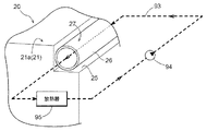
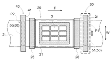
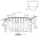
平面視で矩形状の載置台21は、図3に示すように、当該載置台21の上流側端部及び下流側端部の辺部に沿って形成された切欠状溝部25を有する。切欠状溝部25は、載置台21を幅方向Wの全域に亘って切り欠くようにして形成されている。載置台21の上流側端部及び下流側端部は、切欠状溝部25により、それぞれ段差を有するように形成されている。載置部20は、幅方向Wに沿って切欠状溝部25に配置される円筒状部材26を備えている。本実施形態では、円筒状部材26は、支持部材(図示せず)を介して、載置台21との間に隙間を空けた状態で切欠状溝部25に配置されている(図10等も参照)。このような円筒状部材26を備えることで、載置部20は、当該載置部20の上流側端部及び下流側端部に、側面視(幅方向Wに沿って側面から見た状態)で転写シート2側に向かって凸状の曲線状となる曲面部27を有する。すなわち、載置部20は、上流側端部及び下流側端部に、円筒状部材26の表面により構成された曲面部27を有する。曲面部27は、転写シート2に対向する位置に設けられている。なお、円筒状部材26は、載置台21に当接する状態で切欠状溝部25に配置されても良い。このような場合には、載置台21と円筒状部材26との間の熱伝導を抑制するべく、これらの間に断熱部材を介在させることが好ましい。
As shown in FIG. 3, the mounting table 21 having a rectangular shape in plan view has a notch-shaped
円筒状部材26の内周空間は、冷媒が流通する冷媒流通経路93を構成している。すなわち、図3に示すように、熱転写装置1に別途備えられる冷媒流通経路93が、円筒状部材26の内周空間を通るように構成されている。冷媒としては、水等の液体や空気等の気体を用いることができる。冷媒流通経路93は、冷媒を流通させるための経路であり、図3には冷媒循環回路として構成した場合の例を示している。図示の例では、冷媒を圧送するための循環ポンプ94と、冷媒の熱を外気に対して放熱させるための放熱器95とが、冷媒循環回路に介在されている。なお、このような例に限られず、冷媒として空気を用い、これを送風ファン等で連続的に、循環させることなく円筒状部材26の内周空間に供給可能に構成しても良い。なお、図3では下流側の円筒状部材26のみを図示しているが、もちろん、冷媒流通経路93は上流側の円筒状部材26の内周空間をも通るように構成されている。
The inner circumferential space of the
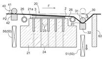
図1に示すように、載置部20に対してシート送り方向Fの両側にそれぞれ隣接して、第一把持部30と第二把持部40とが備えられている。第一把持部30は、載置部20の下流側に隣接配置されている。第一把持部30は、上下の把持部(第一上側把持部31,第一下側把持部32)を有しており、これら2つの把持部31,32で転写シート2を上下方向に把持する。本実施形態では、第一上側把持部31は、幅方向Wに沿って配置された円柱状部材により構成されている。これにより、第一上側把持部31は、対をなす第一下側把持部32に対向する位置に、側面視で曲線状となる曲面部33を有する(図10を参照)。すなわち、第一上側把持部31は、円柱状部材の表面により構成された曲面部33を有する。第一下側把持部32は、幅方向Wに沿って配置された角柱状部材により構成されている。第一把持部30は、2つの把持部31,32の上下方向の位置関係を調整することにより、転写シート2の把持/解放を切替可能に構成されている。本実施形態では、第一上側把持部31の位置を固定した状態で、第一下側把持部32を上昇又は下降させることにより、転写シート2の把持/解放を切り替える。
As shown in FIG. 1, a
第一把持部30は、第1の駆動機構(図示せず)により、シート送り方向F及び幅方向Wに移動可能に構成されている。第一把持部30の2つの把持部31,32は、一体的に、シート送り方向F及び幅方向Wに移動可能に構成されている。本実施形態では、駆動機構により移動可能な第一把持部30の位置分解能は、可動狭持部80の位置分解能よりも高い。第一把持部30の位置分解能は、可動狭持部80の位置分解能に対して、例えば5倍〜20倍(その中でも特に10倍程度)に設定することができる。これにより、可動狭持部80で引き出されて予備位置合わせがなされた転写シート2のシート送り方向Fの位置を、第一把持部30により微調整することができる。また、転写シート2の幅方向Wの位置を微調整することができる。より具体的には、目標位置に対して±1〜2mmの範囲内に収まるように予備位置合わせがなされた転写シート2のシート送り方向F及び幅方向Wの位置を、±0.15〜0.2mmの範囲内に収まるように、高精度な位置調整を行うことができる。
The
第二把持部40は、載置部20の上流側に隣接配置されている。第二把持部40は、上下の把持部(第二上側把持部41,第二下側把持部42)を有しており、これら2つの把持部41,42で転写シート2を上下方向に把持する。本実施形態では、第二上側把持部41は、幅方向Wに沿って配置された円柱状部材により構成されている。これにより、第二上側把持部41は、対をなす第二下側把持部42に対向する位置に、側面視で曲線状となる曲面部43を有する(図10を参照)。すなわち、第二上側把持部41は、円柱状部材の表面により構成された曲面部43を有する。第二下側把持部42は、幅方向Wに沿って配置された角柱状部材により構成されている。第二把持部40は、2つの把持部41,42の上下方向の位置関係を調整することにより、転写シート2の把持/解放を切替可能に構成されている。本実施形態では、第二上側把持部41の位置を固定した状態で、第二下側把持部42を上昇又は下降させることにより、転写シート2の把持/解放を切り替える。
The
第二把持部40は、第2の駆動機構(図示せず)により、幅方向Wに移動可能に構成されている。なお、本実施形態では、第一把持部30とは異なり、シート送り方向Fには移動可能とはされていない。これにより、駆動機構の構成が簡素化されている。第二把持部40の2つの把持部41,42は、一体的に、幅方向Wに移動可能に構成されている。本実施形態では、駆動機構により移動可能な第二把持部40の位置分解能は、第一把持部30の位置分解能と同一に設定されている。これにより、転写シート2の幅方向Wの位置を微調整することができる。
The
支持部50は、第一把持部30及び第二把持部40をそれぞれ昇降可能に支持する。そのため、支持部50は第一支持部51と第二支持部56とを備えている。第一支持部51は、第一把持部30を上下方向に沿って上昇及び下降可能に支持している。第二支持部56は、第二把持部40を上下方向に沿って上昇及び下降可能に支持している。本実施形態では、第一支持部51及び第二支持部56は、第一把持部30及び第二把持部40をそれぞれ独立して昇降させることができるように構成されている。第一支持部51は、それぞれ上昇位置及び下降位置をとり得る。ここで、第一支持部51の上昇位置は、第一上側把持部31の下端部がシート基準位置Sよりも上方となる位置である。また、下降位置は、第一上側把持部31の下端部が当接載置状態の被加飾体3の上面よりも下方となる位置である。第二支持部56に関しても同様である。
The
転写加圧部60は、載置部20に載置された被加飾体3に転写シート2を押し付ける。本実施形態では、転写加圧部60は転写ロールとして構成されている。また、転写加圧部60は、転写テーブル90には固定されておらず、転写テーブル90のスライド移動とは無関係に、シート送り方向Fにおける特定位置に配置されている。さらに、転写加圧部60は、加熱装置(図示せず)によって加熱されているとともに、エアシリンダ61によって昇降可能に構成されている。転写加圧部60は、上昇位置と下降位置とをとり得る。ここで、転写加圧部60の上昇位置は、当該転写加圧部60の下端部がシート基準位置Sよりも上方となる位置である。また、下降位置は、転写加圧部60の下端部の高さが、載置部20に載置された被加飾体3の上面の高さにほぼ等しく、かつ、それ以下となる位置である。
The
転写加圧部60が下降した状態で、転写テーブル90はシート送り方向Fに前進する。これにより、下降した転写加圧部60に対して、転写シート2及び被加飾体3が相対的にシート送り方向Fに前進する。その結果、加熱状態にある転写加圧部60は、シート送り方向Fに前進する転写シート2に対して回転接触しながら、載置台21により支持された被加飾体3に対して転写シート2を順次押し付ける。これにより、被加飾体3の表面に接着層2Bbを介して図柄層2Baが一体化される。なお、この状態では図柄層2Baは基体シート2Aからは剥離しておらず、被加飾体3と転写シート2とが一体化された状態となる。以下では、転写シート2に対して一体化された1つ以上の被加飾体3の各部分を、「複合体4」と称する。
The transfer table 90 advances in the sheet feeding direction F in a state where the
図5に示すように、熱転写装置1は、載置部20の下流側に、転写シート2に対して突出引退可能なシート支持部材63を備えている。シート支持部材63は、転写シート2に向かって、その先端部がシート基準位置Sに一致するまで突出可能とされている。この状態(突出状態)で、シート支持部材63は転写シート2を下方から支持することが可能である。また、シート支持部材63は、下降した状態の第一下側把持部32の上面よりも下方の位置まで引退可能とされている。本実施形態では、シート支持部材63は、先端部における少なくとも上流側端部に、側面視で曲線状となる曲面部64を有する(図10を参照)。本例では、シート支持部材63の先端部の角を丸めることによって当該シート支持部材63に一体的に曲面部64が形成されている。
As shown in FIG. 5, the
図1に示すように、載置部20の下流側には、待機部65が隣接配置されている。待機部65は、載置部20から引き出される複合体4を受け取る。待機部65は、複合体4を搬送するための複数の搬送ローラ66を有する。これら複数の搬送ローラ66は、一体的に昇降可能に構成されている。搬送ローラ66は、上昇位置と下降位置とをとり得るように構成されている。ここで、搬送ローラ66の上昇位置は、当該搬送ローラ66によって搬送される被加飾体3の上面(或いは、被加飾体3に一体化された転写シート2)が、シート基準位置Sに一致する位置である。また、搬送ローラ66の下降位置は、本例では搬送ローラ66の上端部が載置面21aよりも下方となる位置に設定されている。
As shown in FIG. 1, a
待機部65は、幅方向Wに互いに隣接する複数の搬送列部67を備えている。これら複数の搬送列部67により、搬送ローラ66が構成されている。図2に示すように、本実施形態では、待機部65は幅方向Wに3つ並んで配置された第一搬送列部67A、第二搬送列部67B、及び第三搬送列部67Cを備えている。これら3つの搬送列部67A,67B,67Cは、これらのうち少なくとも一組の隣接するものが、シート送り方向Fに沿って相対移動可能に構成されている。本実施形態では、中央の第二搬送列部67Bはシート送り方向Fの位置が固定されており、これに隣接する両側の第一搬送列部67A及び第三搬送列部67Cは、一体的に連結された状態でシート送り方向Fに沿ってスライド可能とされている。中央の第二搬送列部67Bとその両側の搬送列部67A,67Cとの重複領域の長さを変更することで、待機部65のシート送り方向Fの長さを調節することができる。
The
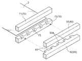
図1に示すように、待機部65の下流側には、固定狭持部70が隣接配置されている。固定狭持部70は、待機部65とともに転写テーブル90に固定されている。固定狭持部70は、転写シート2の高精度位置調整時や切断時等に、当該転写シート2を挟持して保持する。固定狭持部70は、上下の挟持部(上側挟持部71,下側挟持部72)を有しており、これら2つの挟持部71,72で転写シート2を上下方向に挟持する。上下の挟持部71,72は、それぞれ幅方向Wに沿って配置された角柱状部材により構成されている。図4に示すように、下側挟持部72は、可動狭持部80の下側挟持部82に対向する面に形成された凹部73を有する。このような凹部73は、幅方向Wに沿って複数(本例では5つ)、互いに等間隔で形成されている。それぞれの凹部73は、可動狭持部80の下側挟持部82に形成された対応する凸状爪部83に対して嵌合可能とされている。
As shown in FIG. 1, a fixed holding
図1に示すように、固定狭持部70の下流側には、可動狭持部80が配置されている。可動狭持部80は、上下の挟持部(上側挟持部81,下側挟持部82)を有しており、これら2つの挟持部81,82で転写シート2の端部2eを上下方向に挟持する。上下の挟持部81,82は、それぞれ幅方向Wに沿って配置された角柱状部材により構成されている。図4に示すように、下側挟持部82は、固定狭持部70の下側挟持部72に対向する面に形成された凸状爪部83を有する。このような凸状爪部83は、幅方向Wに沿って複数(本例では5つ)、互いに等間隔で形成されている。それぞれの凸状爪部83は、固定狭持部70の下側挟持部72に形成された対応する凹部73に対して嵌合可能とされている。
As shown in FIG. 1, a
それぞれの凸状爪部83は、転写シート2側となる上面側に傾斜面83aを有している。この傾斜面83aは、凸状爪部83の基端部側から先端部側に向かう(シート送り方向Fの上流側に向かう)に従って転写シート2から離間する面となっている。言い換えれば、傾斜面83aは、凸状爪部83の先端部側から基端部側に向かう(シート送り方向Fの下流側に向かう)に従って転写シート2に近接する面となっている。凸状爪部83にこのような傾斜面83aを設けることで、この傾斜面83aによって転写シート2の端部2eを可動狭持部80の上下の挟持部81,82の間へと導き、当該端部2eを適切に挟持することができる。特に、転写シート2の端部2eが垂れ下がってカール状になっている場合でも、当該端部2eを適切に挟持することができる。
Each convex nail | claw part 83 has the
可動狭持部80は、固定狭持部70の下流側に隣接配置された排出部85の上方を、シート送り方向Fに沿ってスライド可能に構成されている(図14を参照)。可動狭持部80が転写シート2の端部2eを挟持した状態で上流側から下流側に向かってスライドすることで、ロール状に保持された転写シート2を引き出すことができる。これにより、載置部20に載置された被加飾体3に対して転写シート2(ここでは特に、転写層2B)を供給することができる。また、転写後の複合体4を下流側へと搬送することができる。なお、可動狭持部80は、転写シート2の解放後に下流側から上流側に向かってスライドすることで、次回の転写シート2の引き出し動作に備える。
The
排出部85は、待機部65から引き出される複合体4を受け取る。図1に示すように、排出部85は、複合体4を受け取るための複数の受取ローラ86を有する。これら複数の受取ローラ86は、個別に昇降可能に構成されている(図15を参照)。それぞれの受取ローラ86は、独立して、上昇位置と下降位置とをとり得るように構成されている。ここで、受取ローラ86の上昇位置及び下降位置は、待機部65の搬送ローラ66の上昇位置及び下降位置とそれぞれ同じである。複合体4が待機部65から引き出される際には、各受取ローラ86は、順次上昇してそれぞれ上昇位置に保持されて複合体4を受け取る。なお、排出部85に複合体4が配置された状態で、転写シート2は、その切断箇所が固定狭持部70の下流側に隣接配置された切断部75の位置となるように位置合わせされる。
The
切断部75は、固定狭持部70と可動狭持部80との間に保持された転写シート2を幅方向Wに切断する。切断部75は、転写シート2の幅方向Wの全域に亘ってスライド可能なカッター(例えば、ロータリーカッターやヒートカッター等)を備えている。排出部85に配置された複合体4は、切断部75によってそれよりも上流側の転写シート2から分離された後、取り出される。
The cutting
2.熱転写方法
次に、図5〜図17を参照して、上述した熱転写装置1を用いて実行される熱転写方法(被加飾体3への模様の転写方法)の手順について説明する。本実施形態に係る熱転写方法は、載置工程、位置決め工程、転写工程、引出工程、切断工程、及び取出工程を備えている。これらは、記載の順に実行されるとともに、逐次繰り返して実行される。本実施形態では、これらの各工程は、制御部6が熱転写装置1の各部の動作を協調的に制御することにより実行される。言い換えれば、制御部6は、各工程において以下に説明する態様で熱転写装置1の各部を制御する。
2. Thermal Transfer Method Next, a procedure of a thermal transfer method (pattern transfer method to the object to be decorated 3) executed using the above-described
なお、本例では、図5に示された、未転写の転写層2Bが平面視で載置部20と重なる位置まで転写シート2が引き出されている状態を初期状態として説明する。この初期状態では、第一把持部30及び第二把持部40はいずれも解放状態にあり、支持部50により上昇位置に保持されている。転写加圧部60は上昇位置にあり、シート支持部材63は突出状態とされている。搬送ローラ66は上昇位置に保持され、各受取ローラ86は下降位置に保持されている。固定狭持部70は挟持状態とされ、可動狭持部80は解放状態にてその可動範囲内における最上流側に位置している。
In this example, the state in which the
2−1.載置工程
載置工程は、引き出された転写シート2と平面視で重なる位置に被加飾体3を載置する工程である。載置工程では、載置台21がレール体22に沿って側方に引き出されて非重複状態とされ、転写シート2と平面視で重ならない位置において、その載置台21に被加飾体3が載置される。なお、本実施形態では、各転写サイクルにおいて、複数の被加飾体3に対して一斉に模様の転写を行う。このため、複数の被加飾体3は、載置台21(載置面21a)における予め定められた領域に、所定規則で配列される。本例では、計9個の被加飾体3が、シート送り方向F及び幅方向Wにそれぞれ3個ずつ並ぶように、互いに所定間隔を隔てて配置される(図7を参照)。なお、転写シート2に形成される転写層2Bの位置も、それに応じて設定されている。その後、載置台21はレール体22に沿って転写シート2の下方に戻されて重複状態とされる。これにより、被加飾体3と転写シート2とが平面視で重なる状態となる。その際、被加飾体3は当接載置状態とされる。
2-1. Placement Step The placement step is a step of placing the object to be decorated 3 at a position that overlaps the drawn
2−2.位置決め工程
位置決め工程は、各被加飾体3に対する転写シート2(ここでは特に、各転写層2B)の位置関係を調整して位置決めを行う工程である。この位置決め工程は、上述した基体シート2Aに施された基準線や基準点の検出に基づく予備位置合わせとは異なる工程である。位置決め工程では、予備位置合わせに比べて高精度な位置決めが行われる。位置決め工程は、第一調整工程、第二調整工程、下降工程、及び吸引工程を備えている。これらは、記載の順に実行される。
2-2. Positioning Step The positioning step is a step of positioning by adjusting the positional relationship of the transfer sheet 2 (here, in particular, each transfer layer 2B) with respect to each decorated
第一調整工程は、被加飾体3に対してシート送り方向Fの下流側において、第一把持部30により転写シート2の第一部分P1を把持して、第一部分P1のシート送り方向Fの位置及び幅方向Wの位置を調整する工程である。第一調整工程では、第一下側把持部32を上昇させて、第一上側把持部31と第一下側把持部32との間に転写シート2の第一部分P1を把持する。ここで、転写シート2の第一部分P1は、各転写サイクルにおいて転写される転写層2Bよりも下流側の、第一把持部30の位置に対応する部分である。上述したように、第一把持部30は高い位置分解能で駆動可能に構成されており、図6に示すように、被加飾体3に対する転写シート2のシート送り方向Fの位置が微調整される。また、図7に示すように、幅方向Wの位置が微調整される。これらの位置は、載置台21の近傍(位置決め対象となる被加飾体3及び転写層2Bの近傍)に設置された位置センサによる検出結果に基づいて微調整される。その際、基体シート2Aに施された基準線及び基準点をそれぞれ検出するセンサによる検出結果を合わせて考慮しても良い。
In the first adjustment step, the first portion P1 of the
この第一調整工程の実行中は、第二把持部40は初期状態(すなわち、解放状態)のまま維持される。このため、転写シート2に作用する張力を維持させたまま、第一調整工程を実行することができ、転写シート2のシート送り方向Fの位置を簡易かつ適切に微調整することができる。すなわち、シート送り方向Fの最上流側には転写シート2がロール状に保持されているので、このロール状部分による逆張力(バックテンション)が転写シート2に作用している。この逆張力が、解放状態の第二把持部40によっては遮断されることがないので、転写シート2の第一部分P1のシート送り方向Fの位置を微調整するだけで、第二部分P2のシート送り方向Fの位置をも微調整することができる。ここで、転写シート2の第二部分P2は、各転写サイクルにおいて転写される転写層2Bよりも上流側の、第二把持部40の位置に対応する部分である。
During the execution of the first adjustment process, the
第二調整工程は、被加飾体3に対してシート送り方向Fの上流側において、第二把持部40により転写シート2の第二部分P2を把持して、第二部分P2の幅方向Wの位置を調整する工程である。第一調整工程の完了時には既に第二部分P2のシート送り方向Fの位置が調整されているので、第二調整工程では、第二部分P2の幅方向Wの位置のみが調整される。第二調整工程では、第二下側把持部42を上昇させて、第二上側把持部41と第二下側把持部42との間に転写シート2の第二部分P2を把持する。上述したように、第二把持部40も高い位置分解能で駆動可能に構成されており、図8に示すように、幅方向Wの位置が微調整される。
In the second adjustment step, the second portion P2 of the
第一調整工程及び第二調整工程を実行することにより、転写前に、被加飾体3に対する転写シート2のシート送り方向Fに沿った位置及び向きを適正化することができる。すなわち、予備位置合わせだけでは不可避となる、被加飾体3に対する転写シート2の位置ずれを、実質的に解消することができる。
By performing the first adjustment process and the second adjustment process, the position and orientation along the sheet feeding direction F of the
なお、本実施形態のように、各転写サイクルで複数の被加飾体3に対して一斉に模様の転写を行う場合には、転写シート2の位置ずれが各被加飾体3に与える影響度は、その個数が多くなるほど(各被加飾体3が小さくなるほど)相対的に大きくなる。よって、そのような場合には、転写工程の実行前に位置決め工程を実行し、被加飾体3に対する転写シート2のシート送り方向Fに沿った位置及び向きを高精度に調整して適正化しておくことが特に有利となる。
In addition, like this embodiment, when transferring a pattern simultaneously with respect to several to-
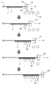
下降工程は、転写シート2が被加飾体3に接触するように、第一部分P1を把持した第一把持部30及び第二部分P2を把持した第二把持部40を下降させる工程である。本実施形態では、図9及び図10に示すように、第一把持部30と第二把持部40とが、第一把持部30、第二把持部40の順に下降位置まで下降される。本実施形態では、第二把持部40が、第一把持部30と同じ降下速度で、当該第一把持部30に対して所定時間だけ遅延して下降される。なお、その際、第一把持部30の下降動作と第二把持部40の下降動作とが部分的に重なっても良い。これにより、転写シート2を、第一部分P1が第二部分P2よりも下方に位置する傾斜姿勢で下降させることができ、転写シート2を下流側から上流側に向かって徐々に被加飾体3に接触させることができる。
The lowering step is a step of lowering the first gripping
下降工程では、下流側から上流側に向かって転写シート2を徐々に被加飾体3に接触させることで、接触領域の中央部における空気の残留を抑制しながら、被加飾体3と転写シート2とを全面的に接触させることができる。つまり、被加飾体3に対して転写シート2を平行姿勢に保ったまま接触させる場合には、接触領域の中央部に空気が残留する可能性があるが、被加飾体3に対して転写シート2を傾斜姿勢で接触させることで、そのような可能性を低減できる。そして、被加飾体3と転写シート2とを全面的に接触させることで、被加飾体3に対して転写シート2が十分に沿った状態を実現するとともに、転写シート2の伸びムラをなくすことができる。
In the descending step, the
ところで、図10に示すように、下降工程の完了時には、第一把持部30及び第二把持部40は下降位置まで下降している。この状態では、第一上側把持部31及び第二上側把持部41の下端部は、当接載置状態の被加飾体3の上面よりも下方に位置している。さらに本実施形態では、第一上側把持部31及び第二上側把持部41は、その上端部が当接載置状態の被加飾体3の上面よりも下方に位置しており、その下端部は載置面21aよりも下方に位置している。このため、転写シート2の第一部分P1及び第二部分P2は、載置面21aよりも下方に位置することになり、転写シート2は載置部20の外形に沿って屈曲する。
By the way, as shown in FIG. 10, the
また、下降工程の完了時には、シート支持部材63は未だ突出状態にあるので、転写シート2における第一部分P1よりも下流側の部分は、上下方向の位置がシート基準位置Sに保たれている。さらに、転写シート2における第二部分P2よりも上流側の部分には、当該部分の上下方向の位置をシート基準位置Sに戻そうとする力が作用する。このため、転写シート2は、第一上側把持部31や第二上側把持部41の下端部側の外形に沿って屈曲する。また、転写シート2は、シート支持部材63の先端部の外形に沿って屈曲する。
Further, when the lowering process is completed, the
このような場合であっても、本実施形態に係る載置部20は、その上流側端部及び下流側端部の双方に、円筒状部材26の表面により構成された曲面部27を有する。また、第一上側把持部31は、第一下側把持部32に対向する下端側に、円柱状部材の表面により構成された曲面部33を有する。同様に、第二上側把持部41は、第二下側把持部42に対向する下端側に、円柱状部材の表面により構成された曲面部43を有する。さらに、シート支持部材63は、先端部における少なくとも上流側端部に曲面部64を有する。よって、載置部20と転写シート2とを、載置部20の曲面部27に沿って滑らかに面接触させることができる。また、第一上側把持部31や第二上側把持部41と転写シート2とを、それぞれ曲面部33,43に沿って滑らかに面接触させることができる。さらに、シート支持部材63と転写シート2とを、曲面部64に沿って滑らかに面接触させることができる。よって、転写シート2の損傷や箔チリの発生を有効に抑制することができる。
Even in such a case, the mounting
さらに本実施形態では、載置部20の曲面部27を構成する円筒状部材26の内周空間を通るように、冷媒流通経路93が設けられている(図3を参照)。これにより、円筒状部材26の内周空間を通って冷媒流通経路93を循環する冷媒との間の熱交換により、曲面部27に沿って接触している転写シート2の部分を冷却することができる。よって、被加飾体3を加熱するために載置台21が加熱される場合であっても、高温状態の載置台21と転写シート2とが融着するのを抑制することができる。つまり、転写シート2の損傷や箔チリの発生を抑制するための構成の一部(円筒状部材26)を有効利用して、載置部20(ここでは、円筒状部材26)と転写シート2との融着を抑制することもできる。なお、円筒状部材26を載置台21との間に隙間を空けて配置することで、載置台21から円筒状部材26への熱伝導が有効に抑制されている。これにより、円筒状部材26を介した冷却構造の実効効率の向上が図られている。
Furthermore, in this embodiment, the refrigerant |
吸引工程は、被加飾体3の下方から転写シート2を吸引する工程である。本実施形態では、図11に示すように、下降工程が完了して被加飾体3に対して転写シート2が全面的に接触した状態で、吸引装置92による吸引動作が行われる。これにより、載置台21の吸引孔24から空気が吸引され、その時に生じる負圧により、載置台21に被加飾体3が吸引保持されるとともに、載置台21に被加飾体3を介して転写シート2が吸引保持される。その結果、被加飾体3と転写シート2との位置関係が保持される。また、被加飾体3と転写シート2とが全面的に接触した状態も保持される。
The suction step is a step of sucking the
なお、下降工程が完了するよりも前に吸引工程を開始することも可能であるが、そのような場合には転写時に気泡が残留する場合があることが確認されている。これは、吸引動作に伴って載置台21及び転写シート2の側方から流れ込んでくる空気によって、泡噛みしやすくなるためであると考えられる。この点、本実施形態では下降工程の完了後に吸引工程を実行するので、上記のような不都合が生じることはほとんどなく、気泡の残留を有効に抑制することができる。
It is possible to start the suction process before the completion of the descending process, but in such a case, it has been confirmed that bubbles may remain during transfer. This is presumably because the air that flows in from the sides of the mounting table 21 and the
2−3.転写工程
転写工程は、被加飾体3に転写シート2を押し付けて、被加飾体3に模様を転写する工程である。転写工程では、転写加圧部60が下降位置まで下降される。その際、図12に示すように、第一部分P1よりも下流側の転写シート2と転写加圧部60とが接触しないように、転写加圧部60の下降動作に合わせてシート支持部材63が非突出状態とされる。また、搬送ローラ66が下降位置まで下降される。その後、転写テーブル90がシート送り方向Fの下流側に向かってスライドされる。これにより、載置台21によって下方から支持された被加飾体3の上を、転写シート2を介して転写加圧部60が転動する。このときの転写加圧部60の熱と圧力とによって、転写シート2上の転写層2Bが被加飾体3の表面に転写される。その結果、被加飾体3の表面に模様(絵柄)が転写される。
2-3. Transfer Process The transfer process is a process in which the
本実施形態では、転写工程の前に実行される位置決め工程において、被加飾体3に対する転写シート2のシート送り方向Fに沿った位置及び向きが適正化され、実質的に位置ずれのない状態となっている。また、被加飾体3と転写シート2とが全面的に接触され、被加飾体3に対して転写シート2が十分に沿った状態となっている。よって、そのような状態で転写工程を行うことで、高い位置精度で被加飾体3への模様付けを行うことができるとともに、完成品における皺の発生や気泡の残留を抑制することができる。
In the present embodiment, in the positioning step executed before the transfer step, the position and orientation along the sheet feeding direction F of the
2−4.引出工程
引出工程は、転写シート2の端部2eを挟持して、転写シート2を引き出す工程である。図13に示すように、引出工程では、第一把持部30及び第二把持部40が、いずれも上昇位置まで上昇されるとともに解放状態とされる。また、転写加圧部60が上昇位置まで上昇されるとともに、載置台21からピン部材23が突出されて被加飾体3が離間載置状態とされる。また、搬送ローラ66が上昇位置まで上昇される。また、可動狭持部80は転写シート2の端部2eを挟持し、固定狭持部70は転写シート2を解放する。なお、シート支持部材63は非突出状態のまま保持され、受取ローラ86は下降位置のまま保持される。その後、図14に示すように、可動狭持部80は、受取ローラ86の上方を、シート送り方向Fに沿って下流側に向かってスライドする。
2-4. Drawing Step The drawing step is a step of pulling out the
可動狭持部80のスライドによって転写シート2が引き出される。その際、載置部20に位置していた複合体4(転写直後のもの)が待機部65に移されるとともに、待機部65に位置していた複合体4(1サイクル前に転写されたもの)が排出部85に移される。また、転写シート2における未転写の転写層2Bの部分が、載置部20に新たに供給される。このような観点からは、引出工程は、被加飾体3との密着状態を維持したまま転写シート2を載置部20から引き出す工程であるとともに、シート保持部10から引き出される転写シート2を載置部20に供給する工程(供給工程)であるとも言える。なお、転写シート2は、次の基準点が検出されるまで引き出されて、予備位置合わせが行われる。
The
引出工程では、ピン部材23によって支持されて離間載置状態とされた被加飾体3は、ピン部材23の上面を滑り、その後、上昇位置に保持された搬送ローラ66によって支持されつつ搬送される。このとき、複合体4は、載置部20から待機部65に亘って転写シート2がシート基準位置Sを維持したままの状態で、待機部65に搬送される。このように、載置部20から待機部65に複合体4が搬送される際に、複合体4が同じ高さで支持可能な状態とされるので、円滑な搬送が可能となる。また、シート基準位置Sに維持される転写シート2には被加飾体3の上面に沿う方向に張力が働きやすくなるので、転写シート2からの被加飾体3の剥離の可能性を有効に低減できる。なお、シート支持部材63は非突出状態とされているので、被加飾体3との干渉が生じることもない。
In the drawing process, the
図15に示すように、個別に昇降可能に構成された受取ローラ86のそれぞれは、可動狭持部80がその上方を通過すると順次上昇して、上昇位置に保持される。これにより、待機部65から排出部85へと、複合体4を同じ高さで円滑に搬送することができる。さらに、載置部20から排出部85までの全体に亘って同じ高さで、転写シート2を引き出すことができる。また、複数の受取ローラ86を個別に昇降可能とすることで、待機部65よりも下流側の領域において、シート送り方向Fにスライド可能な可動狭持部80と排出部85(受取ローラ86)とを平面視で重なるように配置することができる。よって、熱転写装置1の設置スペースを小さくすることができる。
As shown in FIG. 15, each of the receiving
なお、図14に示すように、可動狭持部80により転写シート2が引き出されるのに合わせて、転写テーブル90がシート送り方向Fの上流側にスライド(復帰移動)される。これにより、転写加圧部60は、載置部20に対して相対的に下流側の位置に戻る。なお、この時点では載置部20に被加飾体3が未だ載置されていないため、復帰移動の完了後にシート支持部材63が突出状態とされる(図16を参照)。これにより、転写シート2を下方から支持して、加熱状態にある載置台21に転写シート2が接触するのを防止することができる。
As shown in FIG. 14, the transfer table 90 is slid (returned) upstream in the sheet feeding direction F as the
2−5.切断工程
切断工程は、転写シート2を幅方向Wに切断する工程である。図16に示すように、切断工程では、固定狭持部70も転写シート2を挟持し、固定狭持部70及び可動狭持部80の双方によって転写シート2が挟持される。その後、排出部85に配置された複合体4における、被加飾体3の上流側端部からはみ出した部分が、切断部75によって幅方向Wに切断される。こうして、長尺状の転写シート2からその下流側端部の一部が切り離され、排出部85において、転写シート2が密着した状態の被加飾体3(転写シート2付きの被加飾体3)が得られる。
2-5. Cutting process The cutting process is a process of cutting the
2−6.取出工程
取出工程は、転写シート2付きの被加飾体3を取り出す工程である。図17に示すように、取出工程では、可動狭持部80が解放状態とされ、フリーの状態となった転写シート2付きの被加飾体3が、排出部85から取り出される。その後、全ての受取ローラ86が下降位置まで下降されてから、可動狭持部80がシート送り方向Fの上流側に向かってスライドされ、転写シート2の新たな端部2eの位置まで戻される。また、載置台21のピン部材23が引退されて、新たな被加飾体3が載置台21に載置可能となる。
2-6. Extraction process The extraction process is a process of removing the object to be decorated 3 with the
以後、上記の各工程を繰り返すことで、加飾製品としての転写シート2付きの被加飾体3を、連続的に(断続的に)製造することができる。特に本実施形態では、特徴的な位置決め工程及び引出工程を備えることで、高い位置精度で模様付けがなされた加飾製品を、効率良く製造することができる。
Thereafter, by repeating the above steps, the object to be decorated 3 with the
3.その他の実施形態
最後に、本発明に係る熱転写装置及び熱転写方法の、その他の実施形態について説明する。なお、以下のそれぞれの実施形態で開示される構成は、矛盾が生じない限り、他の実施形態で開示される構成と組み合わせて適用することも可能である。
3. Other Embodiments Finally, other embodiments of the thermal transfer apparatus and the thermal transfer method according to the present invention will be described. Note that the configurations disclosed in the following embodiments can be applied in combination with the configurations disclosed in other embodiments as long as no contradiction arises.
(1)上記の実施形態では、第一調整工程の完了後に第二調整工程を実行する構成を例として説明した。しかし、本発明の実施形態はこれに限定されない。例えば、第一調整工程と第二調整工程とを同時に実行しても良い。この場合、第二部分P2に関しても、シート送り方向F及び幅方向Wの双方の位置を積極的に調整する必要がある。また、このような位置調整を可能とするためには、第二把持部40を、幅方向Wに加えてシート送り方向Fにも移動可能とする必要がある。そして、同時に実行される第一調整工程及び第二調整工程では、転写シート2のシート送り方向Fの位置を調整する際には、第一把持部30と第二把持部40とをシート送り方向Fに同期して移動させる。転写シート2に作用する張力を維持させながら位置調整を行うためである。なお、幅方向Wには、第一把持部30と第二把持部40とを同時に移動させても良いし、順次移動させても良い。
(1) In the above embodiment, the configuration in which the second adjustment step is executed after the completion of the first adjustment step has been described as an example. However, the embodiment of the present invention is not limited to this. For example, you may perform a 1st adjustment process and a 2nd adjustment process simultaneously. In this case, it is necessary to positively adjust both the sheet feeding direction F and the width direction W with respect to the second portion P2. In addition, in order to enable such position adjustment, it is necessary to make the second gripping
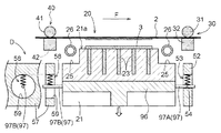
(2)上記の実施形態では、下降工程において、第二把持部40を第一把持部30に対して独立に、所定時間だけ遅延して下降させる構成を例として説明した。しかし、本発明の実施形態はこれに限定されない。例えば、第二把持部40を第一把持部30の下降に対して関係性を持たせつつ、所定時間だけ遅延して下降させても良い。このような構成は、例えば図18に示すように、第一支持部51及び第二支持部56に設けられる遅延機構Dによって実現できる。なお、図18では、第二支持部56に関して、シート送り方向Fから見た側面図を併記している。第一支持部51は、第一内周面54によって画定される円形の第一開口部53が形成された第一支持部材52を有し、第二支持部56は、第二内周面59によって画定される円形の第二開口部58が形成された第二支持部材57を有する。第二開口部58は、第一開口部53よりも大径に形成されている。また、第一支持部51と第二支持部56とは、第一開口部53の上端部の位置と第二開口部58の上端部の位置とが一致する状態で対向して配置されている。そして、シート送り方向Fの両側に延出する一対の連結軸97を有する駆動部材96が、第一支持部51と第二支持部56との間に配置されている。一方の連結軸97Aは、第一開口部53の下端部において第一内周面54に接している。他方の連結軸97Bは、第二開口部58の中心付近において浮遊した状態となっている。これらの各部によって遅延機構Dが構成される。一体の駆動部材96を下降させると、直ちにこれに同期して第一支持部51及び第一把持部30が下降する。その後、やがて連結軸97Bが第二開口部58の下端部において第二内周面59に接すると、駆動部材96に同期して第二支持部56及び第二把持部40も下降する。このような遅延機構Dを備えることにより、第一把持部30と第二把持部40とを、転写シート2の第一部分P1が第二部分P2よりも下方に位置する状態で一体的に下降させることができる。そして、転写シート2を下流側から上流側に向かって徐々に被加飾体3に接触させることができる。その際、第一把持部30と第二把持部40とを一体的に下降させるので、これらを個別に下降させる場合と比較して、駆動機構の構成を簡素化することができる。
(2) In the above-described embodiment, the configuration in which the second gripping
(3)或いは、第一把持部30と第二把持部40とを、完全に同期させつつ、転写シート2の第一部分P1が第二部分P2よりも下方に位置する状態で一体的に下降させても良い。このような構成は、例えば図19に示すように、第一上側把持部31を第二上側把持部41よりも大きく(大径に)形成し、かつ、それぞれの中心の側面視での高さが互いに一致するように配置することで実現できる。このような構成によっても、比較的簡素な構成の駆動機構を用いて、転写シート2を下流側から上流側に向かって徐々に被加飾体3に接触させることができる。また、この構成では、第一上側把持部31と第二上側把持部41とのサイズを異ならせるだけで良いので、この点からも装置構成の簡素化を図ることができる。
(3) Alternatively, the first gripping
(4)上記の実施形態では、下降工程において、第二把持部40を第一把持部30に対して所定時間だけ遅延して同じ降下速度で下降させる構成を例として説明した。しかし、本発明の実施形態はこれに限定されない。第一把持部30と第二把持部40とを異なる降下速度で下降させても良い。例えば、第二把持部40の降下速度を第一把持部30の降下速度よりも遅くすることによっても、転写シート2を下流側から上流側に向かって徐々に被加飾体3に接触させることは可能である。
(4) In the above embodiment, the configuration in which the second gripping
(5)上記の実施形態では、下降工程において、転写シート2が下流側から上流側に向かって徐々に被加飾体3に接触するように、被加飾体3に対して転写シート2を傾斜姿勢で下降させる構成を例として説明した。しかし、本発明の実施形態はこれに限定されない。例えば、転写シート2の全体がほぼ同時に被加飾体3に接触するように、被加飾体3に対して転写シート2を水平姿勢で下降させても良い。このような構成は、第一把持部30と第二把持部40とを同時に同じ降下速度で下降させることによって実現できる。この場合、被加飾体3と転写シート2との接触領域の中央部に多少の空気が残留する可能性はあるが、少なくとも両者を非接触としたままで転写工程を実行する場合と比較して、皺の発生や気泡の残留を低減することができる。
(5) In the above embodiment, in the descending step, the
(6)上記の実施形態では、下降工程の完了後に吸引工程を実行する構成を例として説明した。しかし、本発明の実施形態はこれに限定されない。下降工程が完了するよりも前に吸引工程を開始しても良い。例えば、下降工程において所定範囲(一例として、下流側の70%の範囲)の全体で被加飾体3と転写シート2とが接触した時点で、吸引工程を開始しても良い。
(6) In the above embodiment, the configuration in which the suction step is executed after the completion of the descending step has been described as an example. However, the embodiment of the present invention is not limited to this. The suction process may be started before the descent process is completed. For example, the suction process may be started when the object to be decorated 3 and the
(7)上記の実施形態では、載置部20の曲面部27が、載置台21の切欠状溝部25に配置された円筒状部材26の表面により構成された例について説明した。しかし、本発明の実施形態はこれに限定されない。例えば円柱状部材の表面により曲面部27が構成されても良い。これらの場合において、円筒状部材26又は円柱状部材が、一部、切欠状溝部25の側面や底面に当接する平坦面を有するように形成されても良い。また、例えば図20に示すように、直方体状の載置台21の辺部の角を丸めることによって当該載置台21に一体的に曲面部27を形成しても良い。この場合、曲面部27は、転写シート2に対向する位置となる少なくとも上端部に設ける。なお、載置部20が曲面部27を有さない構成とすることも可能である。
(7) In the above embodiment, the example in which the
(8)上記の実施形態では、第一上側把持部31の曲面部33が、円柱状部材の表面により構成された例について説明した。しかし、本発明の実施形態はこれに限定されない。例えば円筒状部材の表面により曲面部33が構成されても良い。これらの場合において、円柱状部材又は円筒状部材における、第一下側把持部32とは反対側となる上端側が、平坦面を有するように形成されても良い。なお、第一上側把持部31が曲面部33を有さない構成とすることも可能である。第二上側把持部41に関しても同様である。
(8) In the above embodiment, the example in which the
(9)上記の実施形態では、転写工程において転写加圧部60の下降動作に合わせてシート支持部材63が非突出状態とされるとともに搬送ローラ66が下降位置まで下降される例について説明した。しかし、本発明の実施形態はこれに限定されない。例えば下降工程において第一把持部30の下降動作に合わせてシート支持部材63が非突出状態とされるとともに搬送ローラ66が下降位置まで下降されても良い。この場合、非突出状態のシート支持部材63は第一部分P1よりも下流側の転写シート2とは接触しないので、シート支持部材63の先端部は、曲面部64を有することなく角部を有する形状であっても良い。
(9) In the above-described embodiment, the example in which the
(10)上記の実施形態では、シート送り方向F及び幅方向Wにそれぞれ3個ずつ並んで配置される計9個の被加飾体3に対して一斉に模様の転写を行う構成を例として説明した。しかし、本発明の実施形態はこれに限定されない。一度に模様付けされる被加飾体3の個数は、完成品に要求されるサイズ等に応じて、例えば4個,6個,12個,・・・等、適宜設定することができる。なお、単一(1個)の被加飾体3に対して模様の転写を行う場合にも、当然、本発明を適用することができる。
(10) In the above-described embodiment, as an example, a configuration in which a pattern is transferred all at once to a total of nine objects to be decorated 3 arranged side by side in the sheet feeding direction F and the width direction W, respectively. explained. However, the embodiment of the present invention is not limited to this. The number of
(11)上記の実施形態では、本発明をロール式の熱転写装置1に適用した例について説明した。しかし、本発明の実施形態はこれに限定されない。ホットスタンプ式の熱転写装置に本発明を適用することもできる。この場合、転写加圧部60として、転写ロールに代えて平板状の転写版を用いる。
(11) In the above embodiment, the example in which the present invention is applied to the roll-type
(12)その他の構成に関しても、本明細書において開示された実施形態は全ての点で例示であって、本発明の実施形態はこれに限定されない。すなわち、本願の特許請求の範囲に記載されていない構成に関しては、本発明の目的を逸脱しない範囲内で適宜改変することが可能である。 (12) Regarding other configurations as well, the embodiments disclosed herein are illustrative in all respects, and the embodiments of the present invention are not limited thereto. In other words, configurations that are not described in the claims of the present application can be modified as appropriate without departing from the object of the present invention.
本発明は、例えばロール式やホットスタンプ式の熱転写装置及び熱転写方法に利用することができる。 The present invention can be used in, for example, a roll type or hot stamp type thermal transfer apparatus and a thermal transfer method.
1 :熱転写装置
2 :転写シート
3 :被加飾体
6 :制御部
20 :載置部
21 :載置台
24 :吸引孔
25 :切欠状溝部
26 :円筒状部材
27 :曲面部
30 :第一把持部
31 :第一上側把持部
32 :第一下側把持部
33 :曲面部
40 :第二把持部
41 :第二上側把持部
42 :第二下側把持部
43 :曲面部
50 :支持部
51 :第一支持部
56 :第二支持部
92 :吸引装置
93 :冷媒流通経路
P1 :第一部分
P2 :第二部分
F :シート送り方向
W :幅方向
1: Thermal transfer device 2: Transfer sheet 3: Decorated body 6: Control part 20: Placement part 21: Placement table 24: Suction hole 25: Notch-shaped groove part 26: Cylindrical member 27: Curved surface part 30: First grip Part 31: First upper gripping part 32: First lower gripping part 33: Curved part 40: Second gripping part 41: Second upper gripping part 42: Second lower gripping part 43: Curved part 50: Support part 51 : First support part 56: Second support part 92: Suction device 93: Refrigerant flow path P1: First part P2: Second part F: Sheet feeding direction W: Width direction
Claims (11)
平面視で前記転写シートと重なる位置に前記被加飾体を載置可能な載置部と、
前記載置部に対してシート送り方向の下流側に設けられ、前記転写シートを把持可能であり、かつ、前記シート送り方向及び当該シート送り方向に直交する幅方向に移動可能な第一把持部と、
前記載置部に対して前記シート送り方向の上流側に設けられ、前記転写シートを把持可能であり、かつ、少なくとも前記幅方向に移動可能な第二把持部と、
前記第一把持部及び前記第二把持部をそれぞれ昇降可能に支持する支持部と、
を備える熱転写装置。 A thermal transfer apparatus that pulls out the end of a transfer sheet held in a roll shape, supplies the transfer sheet to the object to be decorated, heats it, and continuously transfers the pattern to the object to be decorated. And
A placement unit capable of placing the object to be decorated at a position overlapping the transfer sheet in plan view;
A first gripping portion that is provided downstream of the mounting portion in the sheet feeding direction, is capable of gripping the transfer sheet, and is movable in the sheet feeding direction and a width direction orthogonal to the sheet feeding direction. When,
A second gripping portion provided upstream of the placement portion in the sheet feeding direction, capable of gripping the transfer sheet, and movable at least in the width direction;
A support part for supporting the first grip part and the second grip part so as to be movable up and down;
A thermal transfer apparatus comprising:
前記被加飾体が平面視で前記転写シートと重なるように前記載置部に載置された状態で、
前記制御部は、
前記第一把持部により、前記転写シートの第一部分を把持して当該転写シートの前記シート送り方向の位置及び前記幅方向の位置を調整させ、
その後、前記第二把持部により、前記転写シートの第二部分を把持して当該転写シートの前記幅方向の位置を調整させ、
その後、前記第一部分が前記第二部分よりも下方に位置する状態で、前記第一把持部及び前記第二把持部を下降させる請求項1に記載の熱転写装置。 At least a control unit that performs operation control of the first gripping unit, the second gripping unit, and the support unit,
In a state where the object to be decorated is placed on the placement portion so as to overlap the transfer sheet in plan view,
The controller is
The first gripping part grips the first portion of the transfer sheet to adjust the position in the sheet feeding direction and the position in the width direction of the transfer sheet,
Thereafter, the second gripping portion grips the second portion of the transfer sheet to adjust the position in the width direction of the transfer sheet,
2. The thermal transfer apparatus according to claim 1, wherein the first grip portion and the second grip portion are lowered while the first portion is positioned below the second portion.
前記吸引装置は、前記被加飾体に対して前記転写シートが全面的に接触した状態で吸引動作を行う請求項2に記載の熱転写装置。 The mounting portion has a suction hole whose one end opens on the mounting surface of the mounting portion and whose other end is connected to the suction device,
The thermal transfer device according to claim 2, wherein the suction device performs a suction operation in a state where the transfer sheet is in full contact with the object to be decorated.
前記曲面部が、前記円筒状部材の表面により構成されている請求項4に記載の熱転写装置。 The mounting portion is formed in a rectangular shape in a plan view and has a mounting table having a notch-shaped groove portion formed along a side portion of the upstream-side end portion and the downstream-side end portion, and the notch-shaped groove portion. A cylindrical member to be disposed;
The thermal transfer apparatus according to claim 4, wherein the curved surface portion is configured by a surface of the cylindrical member.
前記冷媒流通経路が、前記円筒状部材の内周空間を通るように構成されている請求項5に記載の熱転写装置。 Provided with a refrigerant distribution channel for distributing the refrigerant,
The thermal transfer device according to claim 5, wherein the refrigerant flow path is configured to pass through an inner circumferential space of the cylindrical member.
前記第一把持部及び前記第二把持部のそれぞれにおける上側把持部が、対をなす下側把持部に対向する位置に、前記幅方向に沿って側面から見た場合に曲線状となる曲面部を有する請求項4から6のいずれか一項に記載の熱転写装置。 The first grip part and the second grip part each have an upper grip part and a lower grip part,
A curved surface portion that is curved when viewed from the side along the width direction at a position where the upper gripping portion of each of the first gripping portion and the second gripping portion faces the paired lower gripping portion. The thermal transfer apparatus according to any one of claims 4 to 6, wherein:
引き出された前記転写シートと平面視で重なる位置に前記被加飾体を載置する載置工程と、
前記載置工程の後、前記被加飾体に対してシート送り方向の下流側において、前記転写シートの第一部分を把持して、前記第一部分の前記シート送り方向の位置及び前記シート送り方向に直交する幅方向の位置を調整する第一調整工程と、
前記第一調整工程の後、前記被加飾体に対して前記シート送り方向の上流側において、前記転写シートの第二部分を把持して、前記第二部分の前記幅方向の位置を調整する第二調整工程と、
前記第二調整工程の後、前記転写シートが前記シート送り方向の下流側から上流側に向かって徐々に前記被加飾体に接触するように、前記転写シートの前記第一部分及び前記第二部分を下降させる下降工程と、
を備える熱転写方法。 This is a thermal transfer method in which an end of a transfer sheet held in a roll shape is pulled out, the transfer sheet is supplied to the object to be decorated and heated, and the pattern is continuously transferred to the object to be decorated. And
A placing step of placing the object to be decorated at a position overlapping the pulled-out transfer sheet in plan view;
After the previous placing step, on the downstream side in the sheet feeding direction with respect to the object to be decorated, the first portion of the transfer sheet is gripped, and the position of the first portion in the sheet feeding direction and the sheet feeding direction are A first adjustment step of adjusting the position in the orthogonal width direction;
After the first adjustment step, the second portion of the transfer sheet is gripped on the upstream side in the sheet feeding direction with respect to the object to be decorated, and the position of the second portion in the width direction is adjusted. A second adjustment step;
After the second adjustment step, the first portion and the second portion of the transfer sheet so that the transfer sheet gradually contacts the object to be decorated from the downstream side to the upstream side in the sheet feeding direction. A lowering step of lowering
A thermal transfer method comprising:
Priority Applications (1)
| Application Number | Priority Date | Filing Date | Title |
|---|---|---|---|
| JP2012241932A JP5945494B2 (en) | 2012-11-01 | 2012-11-01 | Thermal transfer apparatus and thermal transfer method |
Applications Claiming Priority (1)
| Application Number | Priority Date | Filing Date | Title |
|---|---|---|---|
| JP2012241932A JP5945494B2 (en) | 2012-11-01 | 2012-11-01 | Thermal transfer apparatus and thermal transfer method |
Publications (2)
| Publication Number | Publication Date |
|---|---|
| JP2014091237A true JP2014091237A (en) | 2014-05-19 |
| JP5945494B2 JP5945494B2 (en) | 2016-07-05 |
Family
ID=50935684
Family Applications (1)
| Application Number | Title | Priority Date | Filing Date |
|---|---|---|---|
| JP2012241932A Active JP5945494B2 (en) | 2012-11-01 | 2012-11-01 | Thermal transfer apparatus and thermal transfer method |
Country Status (1)
| Country | Link |
|---|---|
| JP (1) | JP5945494B2 (en) |
Cited By (1)
| Publication number | Priority date | Publication date | Assignee | Title |
|---|---|---|---|---|
| KR101483140B1 (en) | 2014-10-30 | 2015-01-16 | 전선아 | Machine for Imprinting Printed Layer onto Window Panel |
Citations (5)
| Publication number | Priority date | Publication date | Assignee | Title |
|---|---|---|---|---|
| JPH06122184A (en) * | 1992-08-31 | 1994-05-06 | Toppan Printing Co Ltd | Image recorder |
| JP2002104350A (en) * | 2000-09-28 | 2002-04-10 | Sanko:Kk | Thermal transfer device for transferring film to metal material |
| JP2003096658A (en) * | 2001-09-25 | 2003-04-03 | Konica Corp | Ink-jet printing apparatus |
| JP2003171043A (en) * | 2001-12-04 | 2003-06-17 | Navitas Co Ltd | Positioning device for belt-shaped film |
| JP2007196513A (en) * | 2006-01-26 | 2007-08-09 | Miyakoshi Printing Machinery Co Ltd | Printing device |
-
2012
- 2012-11-01 JP JP2012241932A patent/JP5945494B2/en active Active
Patent Citations (5)
| Publication number | Priority date | Publication date | Assignee | Title |
|---|---|---|---|---|
| JPH06122184A (en) * | 1992-08-31 | 1994-05-06 | Toppan Printing Co Ltd | Image recorder |
| JP2002104350A (en) * | 2000-09-28 | 2002-04-10 | Sanko:Kk | Thermal transfer device for transferring film to metal material |
| JP2003096658A (en) * | 2001-09-25 | 2003-04-03 | Konica Corp | Ink-jet printing apparatus |
| JP2003171043A (en) * | 2001-12-04 | 2003-06-17 | Navitas Co Ltd | Positioning device for belt-shaped film |
| JP2007196513A (en) * | 2006-01-26 | 2007-08-09 | Miyakoshi Printing Machinery Co Ltd | Printing device |
Cited By (1)
| Publication number | Priority date | Publication date | Assignee | Title |
|---|---|---|---|---|
| KR101483140B1 (en) | 2014-10-30 | 2015-01-16 | 전선아 | Machine for Imprinting Printed Layer onto Window Panel |
Also Published As
| Publication number | Publication date |
|---|---|
| JP5945494B2 (en) | 2016-07-05 |
Similar Documents
| Publication | Publication Date | Title |
|---|---|---|
| JP4614470B1 (en) | Label post-processing apparatus and label processing apparatus | |
| EP2578405A1 (en) | Film transfer apparatus | |
| JP5801591B2 (en) | Thermal transfer apparatus and thermal transfer method | |
| JP3439646B2 (en) | Injection molding simultaneous painting equipment | |
| JP5945494B2 (en) | Thermal transfer apparatus and thermal transfer method | |
| JP5293318B2 (en) | Intermittent film forming method and intermittent film forming apparatus | |
| CA2996367A1 (en) | Production facility and process for manufacturing motor vehicle license plates | |
| US12325219B2 (en) | System for introducing a substrate into a nip | |
| JP2012148474A (en) | Continuous embossing machine and embossing method using the same | |
| JP4144965B2 (en) | Injection molding simultaneous painting method and apparatus | |
| JP4878021B2 (en) | Decorative sheet feeding apparatus and method for producing simultaneously molded decorative molded product | |
| JP6236265B2 (en) | Sheet sticking device and sticking method | |
| CA3158377A1 (en) | Method and apparatus for introducing a substrate into a nip | |
| JP6114970B2 (en) | Skin pack package manufacturing equipment | |
| JP4774243B2 (en) | Photosensitive laminate manufacturing apparatus and manufacturing method | |
| JP2021165208A (en) | Thermal transfer printing device | |
| KR20070106795A (en) | Apparatus and method for producing photosensitive laminate | |
| AU2020200354B2 (en) | Apparatus for application of a conductive pattern to a substrate | |
| JP5531706B2 (en) | Embossed decorative sheet manufacturing apparatus and embossed decorative sheet manufacturing method | |
| JP7751799B2 (en) | Sheet supply device, sheet transport system, forming system, sheet supply method, and sheet transport method | |
| KR20130039421A (en) | Iml injection method using rolling film | |
| KR200346636Y1 (en) | Apparatus for Laminating Green Sheet | |
| JP5712088B2 (en) | Production equipment for sheet molded products | |
| JP5654965B2 (en) | Manufacturing method of sheet molded product | |
| CN121375099A (en) | An automated wood board surface coating machine |
Legal Events
| Date | Code | Title | Description |
|---|---|---|---|
| A621 | Written request for application examination |
Free format text: JAPANESE INTERMEDIATE CODE: A621 Effective date: 20150804 |
|
| A977 | Report on retrieval |
Free format text: JAPANESE INTERMEDIATE CODE: A971007 Effective date: 20160516 |
|
| TRDD | Decision of grant or rejection written | ||
| A01 | Written decision to grant a patent or to grant a registration (utility model) |
Free format text: JAPANESE INTERMEDIATE CODE: A01 Effective date: 20160524 |
|
| A61 | First payment of annual fees (during grant procedure) |
Free format text: JAPANESE INTERMEDIATE CODE: A61 Effective date: 20160530 |
|
| R150 | Certificate of patent or registration of utility model |
Ref document number: 5945494 Country of ref document: JP Free format text: JAPANESE INTERMEDIATE CODE: R150 |
|
| S533 | Written request for registration of change of name |
Free format text: JAPANESE INTERMEDIATE CODE: R313533 |
|
| R350 | Written notification of registration of transfer |
Free format text: JAPANESE INTERMEDIATE CODE: R350 |
|
| R250 | Receipt of annual fees |
Free format text: JAPANESE INTERMEDIATE CODE: R250 |
|
| R250 | Receipt of annual fees |
Free format text: JAPANESE INTERMEDIATE CODE: R250 |
|
| R250 | Receipt of annual fees |
Free format text: JAPANESE INTERMEDIATE CODE: R250 |
|
| R250 | Receipt of annual fees |
Free format text: JAPANESE INTERMEDIATE CODE: R250 |
|
| R250 | Receipt of annual fees |
Free format text: JAPANESE INTERMEDIATE CODE: R250 |
|
| R250 | Receipt of annual fees |
Free format text: JAPANESE INTERMEDIATE CODE: R250 |
|
| R250 | Receipt of annual fees |
Free format text: JAPANESE INTERMEDIATE CODE: R250 |