JP2014088746A - Partition panel device - Google Patents
Partition panel device Download PDFInfo
- Publication number
- JP2014088746A JP2014088746A JP2012240621A JP2012240621A JP2014088746A JP 2014088746 A JP2014088746 A JP 2014088746A JP 2012240621 A JP2012240621 A JP 2012240621A JP 2012240621 A JP2012240621 A JP 2012240621A JP 2014088746 A JP2014088746 A JP 2014088746A
- Authority
- JP
- Japan
- Prior art keywords
- panel
- panel support
- support
- piece
- partition
- Prior art date
- Legal status (The legal status is an assumption and is not a legal conclusion. Google has not performed a legal analysis and makes no representation as to the accuracy of the status listed.)
- Granted
Links
Images
Landscapes
- Securing Of Glass Panes Or The Like (AREA)
Abstract
Description
本発明は、天井と床面とに設けたパネル支持体間に、ガラス等よりなるパネルを建付けしてなる間仕切パネル装置に関する。 The present invention relates to a partition panel device in which a panel made of glass or the like is installed between panel supports provided on a ceiling and a floor surface.
この種の間仕切パネル装置としては、ガラス本体の上部と下部に、それぞれ上部フレームと下部フレームを取り付けたガラスパネルを、天井と床面のパネル支持体に、上部フレームと下部フレームをそれぞれボルトとナットにより固定して取り付けたもの(例えば特許文献1参照)、ガラスパネルの上下の端部に取り付けた縁枠材を、天井と床面のパネル支持体の係合溝に、押え部材をもって係合溝より外れるのを防止しうるように、上下方向に移動可能に嵌合したもの(例えば特許文献2参照)、透明パネルの下部に縁枠部材を取り付け、この縁枠部材を、天井と床面のパネル支持体(横フレーム)に、けんどん(倹飩)式で取り付けたもの(例えば特許文献3参照)などがある。 This type of partition panel device includes a glass panel with an upper frame and a lower frame attached to the upper and lower parts of the glass body, a panel support on the ceiling and floor, respectively, and an upper frame and a lower frame that are bolts and nuts, respectively. (See, for example, Patent Document 1), the edge frame material attached to the upper and lower ends of the glass panel, and the engaging groove with the pressing member in the engaging groove of the panel support on the ceiling and floor surface In order to prevent further detachment, a fitting fitted to be movable in the vertical direction (see, for example, Patent Document 2), an edge frame member is attached to the lower part of the transparent panel, and the edge frame member is attached to the ceiling and the floor surface. There is a panel support (horizontal frame) that is attached in a kendon (倹 飩) manner (for example, see Patent Document 3).
上記特許文献1に記載の間仕切パネル装置においては、床面と天井とのパネル支持体との間に、ガラスパネルを、そのガラス本体の前面を大きく露出させて建付けしうる利点がある。しかしながら、ガラス本体に取り付けた上部フレームと下部フレームを、上部フレームと下部フレームに、ボルトとナットにより固定しているので、多数のガラスパネルを建付けする際の作業効率が悪い。
The partition panel device described in
上記特許文献2に記載の間仕切パネル装置は、パネルを、上下のパネル支持体に上下方向に移動可能に、また、特許文献3に記載の間仕切パネル装置は、パネルを、上下のパネル支持体に、けんどん式により、それぞれ取り付けているので、地震等によりパネルが上下方向にがたつくことがある。特に、けんどん式でパネルを建付けすると、大きな地震等でパネルが上方に移動すると、下部のパネル支持体よりパネルが外れる虞がある。
The partition panel device described in
また、特許文献2及び3に記載の間仕切パネル装置は、いずれも、パネルの下端部を支持するパネル支持体は、床面に設けた幅木やカバー部材の上端よりも上方に位置しているので、足元の幅木やカバー部材、及びパネル支持体のパネル支持部が目立ち過ぎ、見栄えが悪いだけでなく、床面と天井間におけるパネル本体の前面の露出面積が小さくなるという問題がある。
Moreover, as for the partition panel apparatus as described in
本発明は、このような問題点に着目してなされたもので、足元の幅木やパネル支持部等を目立ちにくくして見栄えを向上させうるとともに、パネルを容易に、かつ安定よく建付けすることができ、さらに、パネル前面の露出面積を大とすることができるようにした間仕切パネル装置を提供することを目的としている。 The present invention has been made paying attention to such problems, and can improve the appearance by making the base skirting board and the panel support portion inconspicuous and improve the appearance of the panel easily and stably. Furthermore, it is an object of the present invention to provide a partition panel device that can increase the exposed area of the front surface of the panel.
前記課題を解決するために、本発明の間仕切パネル装置は、
天井に設けた上部パネル支持体と、床面に設けた下部パネル支持体との間に、パネルを建付けしてなる間仕切パネル装置であって、
前記下部パネル支持体を、床面に設けた幅木の少なくとも前面上部を覆うように配設し、前記下部パネル支持体における前記幅木よりも前方に突出する部分の下部を、前上方から後下方に傾斜する直線上に沿って傾斜させたことを特徴としている。
この特徴によれば、人がパネルの前方に立って目線を下方に向けた際に、足元のパネル支持体における幅木より前方に突出する部分や幅木が目立ちにくくなるので、見栄えが向上する。
In order to solve the above-described problem, the partition panel device of the present invention includes:
A partition panel device constructed by installing a panel between an upper panel support provided on the ceiling and a lower panel support provided on the floor surface,
The lower panel support is arranged so as to cover at least the front upper part of the baseboard provided on the floor surface, and the lower part of the lower panel support that protrudes forward from the baseboard is arranged from the front upper side to the rear side. It is characterized by being inclined along a straight line that is inclined downward.
According to this feature, when a person stands in front of the panel and turns his / her line of sight downward, the portion that projects forward from the skirting board or the skirting board on the panel support at the foot becomes less conspicuous, so that the appearance is improved. .
本発明の間仕切パネル装置は、
前記パネルを、パネル本体の上下の端部に幅方向を向く縁材を嵌着したものとし、前記上部の縁材の後面に、前記上部パネル支持体の前部に設けた上部係合溝に上方より係合する上部係合片を設けるとともに、前記下部の縁材の後面下部に、後下方に向かって延出する下部係合片を設け、前記下部のパネル支持体における前記幅木よりも前方に突出する部分に、前記下部の縁材の下面を支持する支持部を有するとともに、前記下部係合片が係合する前上方から後下方に向かって傾斜する下部係合溝を有するパネル支持部を設けたことを特徴としている。
この特徴によれば、上部の縁材における上部係合片を、上部パネル支持体の上部係合溝に、下部の縁材の下部係合片を下部パネル支持体の下部係合溝に、それぞれ、落とし込んで係合させるだけで、パネルを容易に建付けすることができる。また、下部の縁材の下部係合片を、後下方に傾斜させ、この下部係合片を、下部パネル支持体のパネル支持部に設けた後下方に傾斜する下部係合溝に嵌合しているので、大きな地震等でパネルが上下方向に振動しても、下部係合片が下部係合溝より離脱して脱落する虞は小さく、上下のパネル支持体間にパネルを安定よく建付けすることができる。さらに、下部パネル支持体における前上方に傾斜するパネル支持部の上面により、パネルの下端部を支持しているので、パネルの下部前面の露出面積を大とすることができ、体裁がよくなる。
The partition panel device of the present invention is
It is assumed that the panel is fitted with edge members facing in the width direction at the upper and lower ends of the panel body, and the upper engagement groove provided in the front part of the upper panel support is formed on the rear surface of the upper edge member. An upper engagement piece that engages from above is provided, and a lower engagement piece that extends rearward and downward is provided at the lower rear surface of the lower edge member, and more than the baseboard in the lower panel support. A panel support having a support portion that supports the lower surface of the lower edge member at a portion protruding forward, and a lower engagement groove that is inclined from the front upper side to the rear lower side where the lower engagement piece engages. It is characterized by providing a section.
According to this feature, the upper engagement piece in the upper edge member is in the upper engagement groove of the upper panel support, and the lower engagement piece in the lower edge member is in the lower engagement groove of the lower panel support. By simply dropping and engaging, the panel can be easily installed. Further, the lower engaging piece of the lower edge member is inclined rearward and downward, and this lower engaging piece is fitted into the lower engaging groove provided on the panel support portion of the lower panel support body and inclined downward. Therefore, even if the panel vibrates in the vertical direction due to a large earthquake, etc., the lower engagement piece is less likely to be detached from the lower engagement groove and fall off, and the panel is stably installed between the upper and lower panel supports. can do. Furthermore, since the lower end part of the panel is supported by the upper surface of the panel support part inclined upward and forward in the lower panel support body, the exposed area of the lower front surface of the panel can be increased and the appearance is improved.
本発明の間仕切パネル装置は、
前記下部係合片の下面と、該下面に当接する下部係合溝の上面とを、後下方に沿って複数の段差面としたことを特徴としている。
この特徴によれば、複数の段差面により、下部係合片が下部係合溝より離脱するのが規制されるので、パネルの下端部が下部パネル支持体より離脱するのが効果的に防止される。
The partition panel device of the present invention is
The lower surface of the lower engaging piece and the upper surface of the lower engaging groove in contact with the lower surface have a plurality of step surfaces along the rear lower side.
According to this feature, since the lower engagement pieces are prevented from being separated from the lower engagement grooves by the plurality of step surfaces, the lower end portion of the panel is effectively prevented from being separated from the lower panel support. The
本発明の間仕切パネル装置は、
前記上部パネル支持体に、前記パネルの上端部の前面と当接若しくは近接する押え部材を設けたことを特徴としている。
この特徴によれば、縁材の上部係合片が上部のパネル支持体の上部係合溝より離脱しても、パネルの上端部の前面が押え部材により押さえられるので、パネルの上部が前方に転倒するのが防止される。
The partition panel device of the present invention is
The upper panel support is provided with a pressing member that comes into contact with or is close to the front surface of the upper end of the panel.
According to this feature, even if the upper engaging piece of the edge member is separated from the upper engaging groove of the upper panel support, the front surface of the upper end portion of the panel is pressed by the pressing member, so that the upper portion of the panel is moved forward. Falling over is prevented.
本発明の間仕切パネル装置は、
前記パネルをガラスパネルとしたことを特徴としている。
この特徴によれば、パネルをガラスパネルとすると、前述したように、足元の幅木は目立ちにくくなっており、またパネルの下部前面の露出面積が大となっているので、ガラスパネルの特徴である見栄えや意匠的効果を高めることができる。
The partition panel device of the present invention is
The panel is a glass panel.
According to this feature, when the panel is a glass panel, as mentioned above, the base skirting board is less noticeable, and the exposed area of the lower front surface of the panel is large. A certain appearance and design effect can be enhanced.
本発明に係る間仕切パネル装置を実施するための形態を実施例に基づいて以下に説明する。 EMBODIMENT OF THE INVENTION The form for implementing the partition panel apparatus which concerns on this invention is demonstrated below based on an Example.
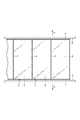
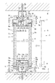
図1及び図2に示すように、実施例1に係る間仕切パネル装置は、オフィス等の室内の床面Fに設けた左右方向を向く下部パネル支持体1と、天井Rに設けた左右方向を向く上部パネル支持体2間に、パネルとしての左右複数のガラスパネル3を、前後に離間させて建付けした二重ガラスパネル構造とされている。なお、以下においては、図2の右方を前、左方を後として説明する。
As shown in FIG.1 and FIG.2, the partition panel apparatus which concerns on Example 1 has the left-right direction provided in the lower
左右に隣接するガラスパネル3、3の対向端部同士は、ポリカーボネート等よりなる上下方向を向く透明な連結部材4により、互いに連結されている。
Opposite ends of the
各ガラスパネル3は、2枚の透明な板ガラス5a、5aを重合して強化した合わせガラスとしたパネル本体5と、このパネル本体5の幅方向の上下の端部に嵌合され、両面接着テープあるいはホットメルト接着材6により固定された下向きコ字状の上部縁材7及び上向きコ字状の下部縁材8とからなっている。下部縁材8の上下寸法は、パネル本体5の下部の支持領域が大となるように、上部縁材7の上下寸法よりも大としてある。さらに、下部縁材8の下部パネル支持体1側の起立片8aの上下寸法を、外側の起立片8bよりも大としてある。なお、現場での建付けや施工時間を短縮するために、上部縁材7と下部縁材8は、工場等においてパネル本体5に予め取り付けられ、ガラスパネル3は完成品として出荷される。
Each
前側のガラスパネル3における上部縁材7の後端上部には、後端に下向きの係止部9aを有する上部係合片9が、全幅に亘って後向きに突設されている。また、後側のガラスパネル3における上部縁材7の前端上部にも、前端に下向きの係止部9aを有する上部係合片9が、前向きに突設されている。
An
前側のガラスパネル3における下部縁材8の後端下部には、後端部が上方及び下方に折曲された下部係合片10が、後下方に向かって傾斜するように突設されている。また、後側のガラスパネル3における下部縁材8の後端下部にも、前側の下部係合片10と前後対称をなす下部係合片10が、前下方に向かって突設されている。下部係合片10の下面には、後下方に沿って上下2段の段差面10aが形成されている。
A
床面Fには、側面視上向きコ字状断面をなす左右方向の幅木11が、複数のアンカーボルト12により固定されている。幅木11内の上面には、左右複数の支持金具13が、アンカーボルト12により共締めして固定されており、各支持金具13の上面板13aには、高さ調整用のアジャスタボルト14が螺合されている。前記下部パネル支持体1は、複数のアジャスタボルト14の上端の受け板14aにより、高さ調節可能として支持されている。
On the floor surface F, left and
前記下部パネル支持体1は、幅木11に、その上半部を覆うようにして上方より外嵌された側面視ほぼ下向きコ字状断面の嵌合部15と、この嵌合部15の前後の下向片15a、15aの下端と連続する、前方及び後方を向く前後対称のパネル支持部16、16とを備えている。前側のパネル支持部16及びその下面は、手前側、すなわち前側のガラスパネル3の前面側から幅木11に向かって後下方に傾斜する直線L上にほぼ沿うように、前上方に傾斜させてあり、また、後側のパネル支持部16は、後側のガラスパネル3の後面側から幅木11に向かって前下方に傾斜する直線L上にほぼ沿うように、後上方に傾斜させてある。本実施例では、直線Lの傾斜角度を、床面(水平面)に対し25度程度としてある。
The
前側のパネル支持部16の前端部と後側のパネル支持部16の後端部は、それぞれ、ガラスパネル3の下部縁材8の下面を支持可能な水平支持部16aとなっている。前側のパネル支持部16における水平支持部16aを除いた上面と、前側の下向片15aの前面との間には、前側のガラスパネル3の下部縁材8の係合片10が斜め前上方より係脱可能に係合する、係合片10と同方向に後下方に向かって傾斜するほぼV字状断面の下部係合溝17が形成されている。この下部係合溝17の上面には、係合片10の下面の上下2段の段差面10aが当接する、それと同形の2段の段差面17aが形成されている。
The front end portion of the front
後側のパネル支持部16における水平支持部16aを除いた上面と、後側の下向片15aの後面との間にも、後側のガラスパネル3の下部縁材8の係合片10が上方より係脱可能に係合する下部係合溝17が、前側の下部係合溝17と前後対称、かつ傾斜方向を反対向きとして形成されている。
The
下部パネル支持体1における嵌合部15の前上端と後上端とには、それぞれ、前後の下部縁材8の係合片10と同じ突出寸法の前向突片18と後向突片19とが突設され、ガラスパネル3を建付けした際、前向突片18の前面は、前側の下部縁材8の後面に、後向突片19の後面は、後側の下部縁材8の前面に、それぞれ当接若しくは近接するようになっている。
A front projecting
嵌合部15の上面には、左右方向を向くカバー取付部材20がねじ止めされ、このカバー取付部材20の上端の後向片20aには、嵌合部15の上方を体裁よく覆う下部カバー部材21が取付けられている。すなわち、この下部カバー部材21は、その下面に突設されたL字状の係止片21aを前記後向片20aの下面に弾性係合させるとともに、下部カバー部材21の前端に突設された後向きL字状の下向片21bの下面を嵌合部15の上面に当接させて装着されている。なお、下部カバー部材21の前後の端部には、前後のガラスパネル3を建付けしたとき、それらの下部縁材10の前面及び後面が当接または近接するようになっている。
A cover mounting member 20 that faces in the left-right direction is screwed to the upper surface of the
天井Rには、左右方向を向く側面視下向きコ字状断面の天レール22が、左右複数のボルト23により固定され、天レール22内の下面には、左右複数の吊支金具24が、ボルト23により共締めして固定されている。各吊支金具24の下面板24aには、高さ調整用のアジャスタボルト25が螺合されている。前記上部パネル支持体2は、複数のアジャスタボルト25の下端の受支板25aにより、高さ調整可能として吊支されている。
A
前記上部パネル支持体2は、天レール22に、上端部を残して下方より嵌合された嵌合部26と、この嵌合部26の下面に下向きに連設され、アジャスタボルト25の受支板25aにより支持された側面視コ字状断面の上部パネル支持部27とを備えている。上部パネル支持部27の前後の下向片27a、27aの下端部に形成された外向折曲部27b、27bの上面には、それぞれ、上方に開口する上部係合溝28、28が形成されている。ガラスパネル3の建付け時において、前側の上部係合溝28には、前側のガラスパネル3における上部縁材7の係合片9の係止部9aが、また、後側の上部係合溝28には、後側のガラスパネル3における上部縁材7の係合片9の係止部9aが、それぞれ上方より係脱可能に係合しうるようになっている。
The
上部パネル支持部27の下方は、上部カバー部材29により体裁よく覆われている。この上部カバー部材29の後部寄りの上面には、上端に前向係合部29aを有する左右方向を向く上向係止片29bが、また、前部寄りの上面には、上向係止片29aよりも短寸の前向係止片30が、それぞれ連設されている。この上向係止片29bの前向係合部29aを、上部パネル支持部27の下面に取り付けた左右複数の係止片31の外向片31aの上面に掛止するとともに、前向係止片30を、パネル支持部27における前側の下向片27aの下部後面に設けた係止溝32に嵌合することにより、上部カバー部材29は、上部パネル支持部27の下面と当接または近接するようにして取り付けられている。なお、上部カバー部材29の前後の端部は、前後のガラスパネル3を建付けした際、それらの後面と前面とに当接または近接するようになっている。
The lower part of the upper panel support part 27 is covered with an
前面側のガラスパネル3を建付けするには、図2の2点鎖線で示すように、まずガラスパネル3を、その下部係合片10の下端が下部パネル支持体1における水平支持部16aよりも上方となるように、上下のパネル支持体1、2の前方に位置させる。
In order to install the
次いで、この状態で、ガラスパネル3を上下のパネル支持体1、2に向かって平行に移動させ、上部縁材7の係止部9aを上部パネル支持体2における上部係合溝28に、下部縁材8の下部係合片10を下部パネル支持体1の下部係合溝17に、それぞれ、ほぼ同時に落とし込んで係合させる。
Next, in this state, the
最後に、ガラスパネル3の上端部の前面に当接または近接する倒立L字状断面の押え部材33を、上部パネル支持体2における嵌合部26の直下の前面に、複数の止めねじ34により固定する。なお、後側のガラスパネル3についても、前側のガラスパネル3と同じ要領で建付けすることができる。
Finally, the holding
これにより、前後のガラスパネル3の建付けが完了し、前後の上部縁材7が、下部パネル支持体1の下向片27aと押え部材33との対向面に当接または近接することにより、ガラスパネル3の上端部が安定よく保持される。また、前後の下部縁材8の起立片8aの後面と前面、及び下部係合片10の後面と前面が、それぞれ、下部パネル支持体1の前向突片18と後向突片19、及び下向片15aの前後の面に当接または近接することにより、ガラスパネル3の下端部も安定よく保持される。
Thereby, the installation of the front and
以上説明したように、実施例1に係る間仕切パネル装置においては、下部パネル支持体1を、幅木11の上半部を覆うように設け、かつ前後のガラスパネル3の下端部を支持するパネル支持部16、16及びその下面を、前側のものについては、その前面側から幅木11に向かって後下方に傾斜する直線L上にほぼ沿うように前上方に傾斜させ、後側のものについては、前下方に傾斜する直線L上にほぼ沿うように後上方に傾斜させてあるので、人がガラスパネル3の前方及び後方に立って目線を下方に向けた際に、足元の幅木11やパネル支持部16が目立ちにくくなり、見栄えが向上する。
As described above, in the partition panel device according to the first embodiment, the
また、上部縁材7の係止部9aを上部パネル支持体2における上部係合溝28に、下部縁材8の下部係合片10を下部パネル支持体1の下部係合溝17に、それぞれ、落とし込んで係合させるだけで、ガラスパネル3を容易に建付けすることができる。しかも、下面に2段の段差面10aを有する下部縁材8の下部係合片10を、前側のガラスパネル3においては後下方に、後側のガラスパネル3においては前下方に、それぞれ傾斜させ、それらの下部係合片10を、下部パネル支持体1のパネル支持部16に設けた、上面に2段の段差面17aを有する後下方及び前下方に傾斜する下部係合溝17に嵌合して建付けしているので、大きな地震等でガラスパネル3が上下方向に振動しても、下部係合片10が下部係合溝17より離脱する虞は小さく、ガラスパネル3の下端部が下部パネル支持体1より外れるのが防止される。
In addition, the engaging
さらに、上部パネル支持体2には、ガラスパネル3の前端部の前面及び後面に当接または近接する押え部材33を取付けているので、上部縁材7の係止部9aが上部パネル支持体2の上部係合溝28より離脱しても、ガラスパネル3の上部が前方及び後方に転倒する虞はない。
Further, the
下部パネル支持体1における前上方及び後下方に傾斜するパネル支持部16の上面により、ガラスパネル3の下端部を支持しているので、ガラスパネル3の下部前面の露出面積を大とすることができ、体裁がよくなる。
Since the lower end part of the
下部パネル支持体1は、アジャスタボルト14と支持金具13を介して、実質的に幅木11の上面により直接支持され、前後のガラスパネル3の重量は、幅木11を介して床面Fにより受けられので、下部パネル支持体1により前後のガラスパネル3の下部を安定よく支持することができる。
The
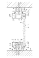
次に、実施例2に係る間仕切パネル装置を、図3を参照して説明する。この実施例においては、前記実施例1の間仕切パネル装置より、後側のガラスパネル3を取外し、前側のガラスパネル3のみを、前記と同形の下部パネル支持体1と上部パネル支持体2との間に建付けしたものである。従って、前記実施例と共通する部材については、それと同じ符号を付して、詳細な説明は省略する。
Next, the partition panel device according to the second embodiment will be described with reference to FIG. In this embodiment, the
この実施例2の下部カバー部材21は、前記と同様の下部カバー部材21の後端に、後側のパネル支持部16の上方を覆いうる倒立L字状断面の後部カバー片21cを連設し、その後下面を後側のパネル支持部16の後端部上面に当接させてある。また、上部パネル支持体2に取り付けた後側の押え部材33の下端には、上部パネル支持体2の下方と後側の下向片27aの後面を覆いうる前向カバー片33aが連設されている。後部カバー片21cと前向カバー片33aの後面は、互いに上下方向に同一面となるように整合させてある。
In the
実施例2に係る間仕切パネル装置においても、前記実施例1に係る間仕切パネル装置と同様の作用効果を奏することができる。 In the partition panel device according to the second embodiment, the same effects as the partition panel device according to the first embodiment can be achieved.
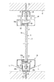
次に、実施例3に係る間仕切パネル装置を、図4を参照して説明する。前記実施例と共通する部材については、それと同じ符号を付して、詳細な説明は省略する。 Next, a partition panel device according to Example 3 will be described with reference to FIG. About the member which is common in the said Example, the same code | symbol is attached | subjected and it abbreviate | omits detailed description.
この実施例においては、幅木11より外側の前部と後部が中空をなす下部パネル支持体35と上部パネル支持体36とにおける中央部の対向面に、対向面方向に開口する凹部37、37を設けてある。
In this embodiment, the
これら上下の凹部37、37に、上下の端部にコ字状断面の縁材38、38を取り付けたガラスパネル3を、上下のパネル支持体35、36の一方である後面の外側端より挿入させて嵌合したのち、上下の縁材38、38の後面を、それぞれ、上部パネル支持体36の後部寄りの垂下片36aにねじ止めした上向コ字状断面の保持部材39の前面と、下部パネル支持体35の後部寄りの上向片35aにねじ止めした上向コ字状断面の保持部材40の前面とにより、前方に押圧して保持することにより、ガラスパネル3を上下のパネル支持体35、36の対向面間に建付けしたものである。
The
下部パネル支持体35における幅木11の前方と後方に突出する部分の下端部35b、35bは、それぞれ、前記実施例1と同様に、前方及び後方から幅木11に向かって後下方及び前下方に傾斜する直線L上にほぼ沿うように、前上方と後上方とに傾斜させてある。
The
この実施例3の間仕切パネル装置においても、下部パネル支持体35における幅木11の前方と後方に突出する部分の下端部35b、35bを、それぞれ、前上方と後上方とに傾斜させてあるので、足元の幅木11が目立ちにくくなり、見栄えが向上する。
Also in the partition panel device of the third embodiment, the
以上、本発明の実施例を図面により説明してきたが、具体的な構成は前記実施例に限定されるものではなく、本発明の要旨を逸脱しない範囲内における変形や追加があっても、本発明に含まれる。 Although the embodiments of the present invention have been described with reference to the drawings, the specific configuration is not limited to the above-described embodiments, and the present invention can be modified or added within the scope not departing from the gist of the present invention. Included in the invention.
例えば、前記各実施例では、下部パネル支持体1、35を、幅木11の上半部を覆うように設けてあるが、ほぼ幅木11全体を覆うように設けてもよい。
For example, in each of the above embodiments, the lower panel supports 1 and 35 are provided so as to cover the upper half of the skirting
また、前記各実施例1及び2では、下部係合片10の下面とパネル支持部16の上面に、段差面10a、17aを形成したが、このような段差面10a、17aを省略して実施することもある。
Further, in each of the first and second embodiments, the step surfaces 10a and 17a are formed on the lower surface of the
さらに、下部パネル支持体1のパネル支持部16の傾斜角度、及び下部パネル支持体35の下端部の傾斜角度は、25度よりも大または小としてもよい。
Furthermore, the inclination angle of the
本発明は、前記ガラスパネル3を用いた間仕切パネル装置の外、通常のボード状のパネル等を用いた間仕切パネル装置にも適用することができる。
The present invention can be applied to a partition panel device using a normal board-like panel or the like in addition to the partition panel device using the
1 下部パネル支持体
2 上部パネル支持体
3 ガラスパネル(パネル)
4 連結部材
5 パネル本体
5a 板ガラス
6 両面接着テープあるいはホットメルト接着材
7 上部縁材
8 下部縁材
8a 起立片
8b 起立片
9 上部係合片
9a 係止部
10 下部係合片
10a 段差面
11 幅木
12 アンカーボルト
13 支持金具
13a 上面板
14 アジャスタボルト
14a 受け板
15 嵌合部
15a 下向片
16 パネル支持部
16a 水平支持部
17 下部係合溝
17a 段差面
18 前向突片
19 後向突片
20 カバー取付部材
20a 後向片
21 下部カバー部材
21a 係止片
21b 下向片
21c 後部カバー片
22 天レール
23 ボルト
24 吊支金具
24a 下面板
25 アジャスタボルト
25a 受支板
26 嵌合部
27 上部パネル支持部
27a 下向片
27b 外向折曲部
28 上部係合溝
29 上部カバー部材
29a 前向係合部
29b 上向係止片
30 前向係止片
31 係止片
31a 外向片
32 係止溝
33 押え部材
33a 前向カバー片
34 止めねじ
35 下部パネル支持体
35a 上向片
35b 下端部
36 上部パネル支持体
36a 垂下片
37 凹部
38 縁材
39 保持部材
40 保持部材
1
4 Connecting
Claims (5)
前記下部パネル支持体を、床面に設けた幅木の少なくとも前面上部を覆うように配設し、前記下部パネル支持体における前記幅木よりも前方に突出する部分の下部を、前上方から後下方に傾斜する直線上に沿って傾斜させたことを特徴とする間仕切パネル装置。 A partition panel device constructed by installing a panel between an upper panel support provided on the ceiling and a lower panel support provided on the floor surface,
The lower panel support is arranged so as to cover at least the front upper part of the baseboard provided on the floor surface, and the lower part of the lower panel support that protrudes forward from the baseboard is arranged from the front upper side to the rear side. A partition panel device, wherein the partition panel device is inclined along a straight line inclined downward.
Priority Applications (1)
| Application Number | Priority Date | Filing Date | Title |
|---|---|---|---|
| JP2012240621A JP6121688B2 (en) | 2012-10-31 | 2012-10-31 | Partition panel device |
Applications Claiming Priority (1)
| Application Number | Priority Date | Filing Date | Title |
|---|---|---|---|
| JP2012240621A JP6121688B2 (en) | 2012-10-31 | 2012-10-31 | Partition panel device |
Publications (2)
| Publication Number | Publication Date |
|---|---|
| JP2014088746A true JP2014088746A (en) | 2014-05-15 |
| JP6121688B2 JP6121688B2 (en) | 2017-04-26 |
Family
ID=50790843
Family Applications (1)
| Application Number | Title | Priority Date | Filing Date |
|---|---|---|---|
| JP2012240621A Active JP6121688B2 (en) | 2012-10-31 | 2012-10-31 | Partition panel device |
Country Status (1)
| Country | Link |
|---|---|
| JP (1) | JP6121688B2 (en) |
Cited By (4)
| Publication number | Priority date | Publication date | Assignee | Title |
|---|---|---|---|---|
| KR20230078252A (en) * | 2021-11-26 | 2023-06-02 | 주식회사 아이넌 | Hanger bolt structure for setting building room space partitioning panel |
| KR20230078247A (en) * | 2021-11-26 | 2023-06-02 | 주식회사 아이넌 | Hanger bracket structure for setting building room space partitioning panel |
| KR20230078255A (en) * | 2021-11-26 | 2023-06-02 | 주식회사 아이넌 | Building room space partitioning panel setting method |
| JP7642962B2 (en) | 2021-03-04 | 2025-03-11 | 小松ウオール工業株式会社 | Adjustment mechanism for bottom frame in partition device |
Citations (4)
| Publication number | Priority date | Publication date | Assignee | Title |
|---|---|---|---|---|
| FR2238020A1 (en) * | 1973-07-19 | 1975-02-14 | Pollet Sa | Fire resistant partition wall panels - are erected on vert. grid allowing warping and expansion without collapsing |
| JPH11241442A (en) * | 1997-12-17 | 1999-09-07 | Nippon Light Metal Co Ltd | Wall panel mounting structure for clean room |
| JP2005009263A (en) * | 2003-06-23 | 2005-01-13 | Mitsubishi Kagaku Sanshi Corp | Partition wall |
| JP2008121267A (en) * | 2006-11-10 | 2008-05-29 | Kokuyo Co Ltd | Partition device |
-
2012
- 2012-10-31 JP JP2012240621A patent/JP6121688B2/en active Active
Patent Citations (4)
| Publication number | Priority date | Publication date | Assignee | Title |
|---|---|---|---|---|
| FR2238020A1 (en) * | 1973-07-19 | 1975-02-14 | Pollet Sa | Fire resistant partition wall panels - are erected on vert. grid allowing warping and expansion without collapsing |
| JPH11241442A (en) * | 1997-12-17 | 1999-09-07 | Nippon Light Metal Co Ltd | Wall panel mounting structure for clean room |
| JP2005009263A (en) * | 2003-06-23 | 2005-01-13 | Mitsubishi Kagaku Sanshi Corp | Partition wall |
| JP2008121267A (en) * | 2006-11-10 | 2008-05-29 | Kokuyo Co Ltd | Partition device |
Cited By (7)
| Publication number | Priority date | Publication date | Assignee | Title |
|---|---|---|---|---|
| JP7642962B2 (en) | 2021-03-04 | 2025-03-11 | 小松ウオール工業株式会社 | Adjustment mechanism for bottom frame in partition device |
| KR20230078252A (en) * | 2021-11-26 | 2023-06-02 | 주식회사 아이넌 | Hanger bolt structure for setting building room space partitioning panel |
| KR20230078247A (en) * | 2021-11-26 | 2023-06-02 | 주식회사 아이넌 | Hanger bracket structure for setting building room space partitioning panel |
| KR20230078255A (en) * | 2021-11-26 | 2023-06-02 | 주식회사 아이넌 | Building room space partitioning panel setting method |
| KR102648595B1 (en) * | 2021-11-26 | 2024-03-18 | 주식회사 아이넌 | Hanger bracket structure for setting building room space partitioning panel |
| KR102648610B1 (en) * | 2021-11-26 | 2024-03-18 | 주식회사 아이넌 | Building room space partitioning panel setting method |
| KR102667908B1 (en) * | 2021-11-26 | 2024-05-21 | 주식회사 아이넌 | Hanger bolt structure for setting building room space partitioning panel |
Also Published As
| Publication number | Publication date |
|---|---|
| JP6121688B2 (en) | 2017-04-26 |
Similar Documents
| Publication | Publication Date | Title |
|---|---|---|
| JP6121687B2 (en) | Partition panel device | |
| JP6121688B2 (en) | Partition panel device | |
| WO2013110067A4 (en) | Vertical wall mount system | |
| CN201125470Y (en) | Post-installed beam curtain wall | |
| KR102054616B1 (en) | Composite insulation panel constructing method | |
| DK2219495T3 (en) | Hidden and adjustable support for wall mounting of a suspended furniture element | |
| JP6233020B2 (en) | Glass panel equipment | |
| CN105064588A (en) | A brand-new composite suspended ceiling and its installation method | |
| JP6689795B2 (en) | Partition panel device | |
| JP6719968B2 (en) | Partition panel device | |
| KR200484378Y1 (en) | Display booth easy to install and remove of panel | |
| KR20190104916A (en) | Combination structure of canopy | |
| JP5539811B2 (en) | Lighting device installation structure | |
| KR20140145371A (en) | Light Emitting Diode Flat Panel Lighting | |
| CN102877589A (en) | Adjustable edge strip accommodation installation structure for indoor ceiling wall surface | |
| JP4188767B2 (en) | Partition panel device | |
| CN204804139U (en) | Brand -new compound furred ceiling | |
| RU2006133878A (en) | METAL FASTENING FOR EXTERNAL WALL DESIGN AND EXTERNAL WALL DESIGN | |
| JP2017089229A (en) | Partition panel device | |
| JP3193455U (en) | Mounting structure of shelf support panel | |
| KR101081041B1 (en) | Structure of installing round well type's ceiling, using PVC | |
| JP2005023632A (en) | Partition panel | |
| CN104314222B (en) | Compound-silver mirror ceiling system | |
| JP4188745B2 (en) | Partition panel installation structure | |
| JP4777089B2 (en) | Bathroom counter and bathroom unit having this bathroom counter |
Legal Events
| Date | Code | Title | Description |
|---|---|---|---|
| RD04 | Notification of resignation of power of attorney |
Free format text: JAPANESE INTERMEDIATE CODE: A7424 Effective date: 20150630 |
|
| A621 | Written request for application examination |
Free format text: JAPANESE INTERMEDIATE CODE: A621 Effective date: 20151005 |
|
| A977 | Report on retrieval |
Free format text: JAPANESE INTERMEDIATE CODE: A971007 Effective date: 20160819 |
|
| A131 | Notification of reasons for refusal |
Free format text: JAPANESE INTERMEDIATE CODE: A131 Effective date: 20160830 |
|
| A521 | Request for written amendment filed |
Free format text: JAPANESE INTERMEDIATE CODE: A523 Effective date: 20161025 |
|
| TRDD | Decision of grant or rejection written | ||
| A01 | Written decision to grant a patent or to grant a registration (utility model) |
Free format text: JAPANESE INTERMEDIATE CODE: A01 Effective date: 20170307 |
|
| A61 | First payment of annual fees (during grant procedure) |
Free format text: JAPANESE INTERMEDIATE CODE: A61 Effective date: 20170330 |
|
| R150 | Certificate of patent or registration of utility model |
Ref document number: 6121688 Country of ref document: JP Free format text: JAPANESE INTERMEDIATE CODE: R150 |
|
| S533 | Written request for registration of change of name |
Free format text: JAPANESE INTERMEDIATE CODE: R313533 |
|
| R350 | Written notification of registration of transfer |
Free format text: JAPANESE INTERMEDIATE CODE: R350 |
|
| R250 | Receipt of annual fees |
Free format text: JAPANESE INTERMEDIATE CODE: R250 |
|
| R250 | Receipt of annual fees |
Free format text: JAPANESE INTERMEDIATE CODE: R250 |
|
| R250 | Receipt of annual fees |
Free format text: JAPANESE INTERMEDIATE CODE: R250 |
|
| R250 | Receipt of annual fees |
Free format text: JAPANESE INTERMEDIATE CODE: R250 |
|
| R250 | Receipt of annual fees |
Free format text: JAPANESE INTERMEDIATE CODE: R250 |
|
| R250 | Receipt of annual fees |
Free format text: JAPANESE INTERMEDIATE CODE: R250 |
|
| R250 | Receipt of annual fees |
Free format text: JAPANESE INTERMEDIATE CODE: R250 |