JP2014088739A - Shelf and set for execution of shelf - Google Patents
Shelf and set for execution of shelf Download PDFInfo
- Publication number
- JP2014088739A JP2014088739A JP2012240422A JP2012240422A JP2014088739A JP 2014088739 A JP2014088739 A JP 2014088739A JP 2012240422 A JP2012240422 A JP 2012240422A JP 2012240422 A JP2012240422 A JP 2012240422A JP 2014088739 A JP2014088739 A JP 2014088739A
- Authority
- JP
- Japan
- Prior art keywords
- shelf
- plate portion
- horizontal plate
- construction member
- plate
- Prior art date
- Legal status (The legal status is an assumption and is not a legal conclusion. Google has not performed a legal analysis and makes no representation as to the accuracy of the status listed.)
- Pending
Links
- 239000000463 material Substances 0.000 claims abstract description 25
- 238000010276 construction Methods 0.000 claims description 115
- 210000001061 forehead Anatomy 0.000 claims description 28
- 229920003002 synthetic resin Polymers 0.000 claims description 10
- 239000000057 synthetic resin Substances 0.000 claims description 10
- 238000000034 method Methods 0.000 description 10
- 238000007373 indentation Methods 0.000 description 7
- 238000004519 manufacturing process Methods 0.000 description 5
- 239000000853 adhesive Substances 0.000 description 3
- 230000001070 adhesive effect Effects 0.000 description 3
- 230000035699 permeability Effects 0.000 description 3
- 230000000694 effects Effects 0.000 description 2
- BZHJMEDXRYGGRV-UHFFFAOYSA-N Vinyl chloride Chemical compound ClC=C BZHJMEDXRYGGRV-UHFFFAOYSA-N 0.000 description 1
- 229920000122 acrylonitrile butadiene styrene Polymers 0.000 description 1
- 210000000245 forearm Anatomy 0.000 description 1
- 238000009434 installation Methods 0.000 description 1
- 239000002648 laminated material Substances 0.000 description 1
- 239000002184 metal Substances 0.000 description 1
- 239000002245 particle Substances 0.000 description 1
- 239000011120 plywood Substances 0.000 description 1
- 229920005989 resin Polymers 0.000 description 1
- 239000011347 resin Substances 0.000 description 1
- 238000009423 ventilation Methods 0.000 description 1
Images

Landscapes
- Assembled Shelves (AREA)
Abstract
Description
本発明は、押入やクロゼットの中段棚、枕棚などの棚およびその施工に用いる棚施工用セットに関する。 The present invention relates to a shelf such as a press shelf, a middle shelf of a closet, a pillow shelf, and a shelf construction set used for the construction thereof.
従来、押入の内部には、中段棚や枕棚が設けられている(例えば、特許文献1、2参照)。図10は、押入の中段棚や枕棚の一例を示す概略断面図である。本例の棚100において、102は前框、104は棚板を示す。
Conventionally, a middle shelf and a pillow shelf are provided inside the press-in (see, for example, Patent Documents 1 and 2). FIG. 10 is a schematic cross-sectional view illustrating an example of a middle shelf or a pillow shelf in the press. In the
前框102は、四角形の板材103の上面前後方向中間部に長手方向に沿って係合溝106が設けられているとともに、係合溝106の前方に前側突出部108、後方に上記前側突出部108よりも高さが低い後側突出部110が形成されたものである。また、板材103の前面から下面にかけては化粧紙112(図中点線で示す)が貼られている。
The
棚板104は、四角形の板材105の前端部下面に係合凸部114、その後方に係合凹部116が形成されたものである。また、板材105の上面には化粧紙118(図中点線で示す)が貼られている。
The
本例の棚100を施工する場合、前框102および四角棒状の受桟(図示せず)を押入内に取り付け、棚板104の係合凸部114を前框102の係合溝106に挿入し、前框102の後側突出部110を棚板104の係合凹部116に挿入した状態で、棚板104を前框102および受桟に固定する。
When constructing the
しかし、図10に示した棚には、以下のような問題があった。
(1)棚板104の係合凸部114を前框102の係合溝106に挿入し、前框102の後側突出部110を棚板104の係合凹部116に挿入した状態で、棚板104を前框102および受桟に固定するものであるため、棚板104の配置態様が1種類しかなく、棚板104の配置態様の自由度が無い。
(2)枕棚のように棚板104の取り付け位置が目線より高くなる場合は、棚板104を上下反転させて化粧紙118が下から見えるように施工することが考えられる。しかし、図10の棚は、棚板104の係合凸部114を前框102の係合溝106に挿入し、前框102の後側突出部110を棚板104の係合凹部116に挿入する必要があるため、棚板104を上下反転させて施工することができない。
(3)前框102に係合溝106、前側突出部108、後側突出部110の加工が必要であり、棚板104に係合凸部114、係合凹部116の加工が必要であるため、前框102および棚板104の製造コストが高くなる。
(4)前框102の前面を化粧紙112で化粧加工しているが、化粧紙112は強度が低いため、前框102の前面に凹みや傷が付きやすい。
(5)前框102の前面を化粧紙112で化粧加工しているが、化粧紙112は薄いため、前框102の表面から下地(板材103の表面)が透けて見えたり、前框102の表面に下地(同前)の凹凸が現れたりすることがある。
(6)上記のように前框102の表面から下地が透けて見えたり、前框102の表面に下地の凹凸が現れたりすることがあるため、板材103として表面品質の良いものしか使えない。
However, the shelf shown in FIG. 10 has the following problems.
(1) With the
(2) When the attachment position of the
(3) Because it is necessary to process the
(4) Although the front surface of the
(5) The front surface of the
(6) As described above, the base can be seen through from the surface of the
本発明は、上述した事情に鑑みてなされたもので、棚板の配置態様の自由度を有し、また、棚板を上下反転させて施工することができるとともに、前框および棚板のいずれにも加工を行う必要がなく、したがって前框および棚板の製造コストを下げることができ、しかも前框の前面に凹みや傷が付いたり、前框の表面から下地が透けて見えたり、前框の表面に下地の凹凸が現れたりすることのない棚およびその施工に用いる棚施工用セットを提供することを目的とする。 The present invention has been made in view of the above-described circumstances, has a degree of freedom in arrangement of shelf boards, and can be constructed by inverting the shelf board up and down, There is no need to process the front plate, so the manufacturing cost of the front and shelf plates can be reduced, and the front surface of the front plate is dented or scratched. It is an object of the present invention to provide a shelf in which unevenness of the foundation does not appear on the surface of the ridge and a shelf construction set used for the construction.
本発明は、前記目的を達成するため、
棚施工用部材と、前框と、棚板とを備えた棚であって、
前記棚施工用部材は、四角形の垂直板部と、前記垂直板部の下端から後方に突出した下側水平板部と、前記垂直板部の上下方向中間部から後方に突出した中間水平板部と、前記垂直板部の上端から後方に突出した上側水平板部とを有し、前記下側水平板部と前記中間水平板部との間の距離が前記前框の高さとほぼ等しく、前記中間水平板部と前記上側水平板部との間の距離が前記棚板の厚さとほぼ等しいものであり、
前記前框は、上面および下面が平面状で、横方向の長さが前記棚施工用部材の横方向の長さとほぼ等しい四角板材からなるものであり、
前記棚板は、上面および下面が平面状で、横方向の長さが前記棚施工用部材の横方向の長さより短い複数の四角板材からなるものであり、
前記下側水平板部と前記中間水平板部との間に前記前框が挿入され、前記中間水平板部と前記上側水平板部との間に前記棚板の複数の四角板材の一部または全部の前端部が挿入されていることを特徴とする棚を提供する。
In order to achieve the above object, the present invention provides
It is a shelf provided with a shelf construction member, an outpost, and a shelf board,
The shelf construction member includes a rectangular vertical plate portion, a lower horizontal plate portion protruding rearward from a lower end of the vertical plate portion, and an intermediate horizontal plate portion protruding rearward from an intermediate portion in the vertical direction of the vertical plate portion. And an upper horizontal plate portion that protrudes rearward from the upper end of the vertical plate portion, and the distance between the lower horizontal plate portion and the intermediate horizontal plate portion is substantially equal to the height of the forehead, The distance between the intermediate horizontal plate portion and the upper horizontal plate portion is substantially equal to the thickness of the shelf plate,
The front wing is a flat plate having an upper surface and a lower surface, and is composed of a square plate material whose lateral length is substantially equal to the lateral length of the shelf construction member,
The shelf board is composed of a plurality of square plate materials whose upper and lower surfaces are planar and whose lateral length is shorter than the lateral length of the shelf construction member,
The front wing is inserted between the lower horizontal plate portion and the intermediate horizontal plate portion, and a part of the plurality of square plate members of the shelf plate between the intermediate horizontal plate portion and the upper horizontal plate portion or There is provided a shelf characterized in that all front end portions are inserted.
また、本発明は、
棚施工用部材と、前框と、棚板とを備えた棚施工用セットであって、
前記棚施工用部材は、四角形の垂直板部と、前記垂直板部の下端から後方に突出した下側水平板部と、前記垂直板部の上下方向中間部から後方に突出した中間水平板部と、前記垂直板部の上端から後方に突出した上側水平板部とを有し、前記下側水平板部と前記中間水平板部との間の距離が前記前框の高さとほぼ等しく、前記中間水平板部と前記上側水平板部との間の距離が前記棚板の厚さとほぼ等しいものであり、
前記前框は、上面および下面が平面状で、横方向の長さが前記棚施工用部材の横方向の長さとほぼ等しい四角板材からなるものであり、
前記棚板は、上面および下面が平面状で、横方向の長さが前記棚施工用部材の横方向の長さより短い複数の四角板材からなるものであり、
前記下側水平板部と前記中間水平板部との間に前記前框を挿入し、前記中間水平板部と前記上側水平板部との間に前記棚板の複数の四角板材の一部または全部の前端部を挿入することを特徴とする棚施工用セットを提供する。
The present invention also provides:
It is a set for shelf construction provided with a member for shelf construction, an outpost, and a shelf board,
The shelf construction member includes a rectangular vertical plate portion, a lower horizontal plate portion protruding rearward from a lower end of the vertical plate portion, and an intermediate horizontal plate portion protruding rearward from an intermediate portion in the vertical direction of the vertical plate portion. And an upper horizontal plate portion that protrudes rearward from the upper end of the vertical plate portion, and the distance between the lower horizontal plate portion and the intermediate horizontal plate portion is substantially equal to the height of the forehead, The distance between the intermediate horizontal plate portion and the upper horizontal plate portion is substantially equal to the thickness of the shelf plate,
The front wing is a flat plate having an upper surface and a lower surface, and is composed of a square plate material whose lateral length is substantially equal to the lateral length of the shelf construction member,
The shelf board is composed of a plurality of square plate materials whose upper and lower surfaces are planar and whose lateral length is shorter than the lateral length of the shelf construction member,
A part of the plurality of square plate members of the shelf plate is inserted between the lower horizontal plate portion and the intermediate horizontal plate portion, and between the intermediate horizontal plate portion and the upper horizontal plate portion, or There is provided a shelf construction set characterized by inserting all front end portions.
本発明において、棚板の各四角板材の横方向の長さAと棚施工用部材の横方向の長さBとの比A:Bは、A:B=1:2〜1:10、より好ましくはA:B=1:5〜1:8の範囲にあり、かつ、棚板の複数の四角板材の横方向の長さの合計Cと棚施工用部材の横方向の長さBとの比C:Bは、C:B=1:0.5〜1:1.5、より好ましくはC:B=1:0.8〜1:1.2の範囲にある構成とすることができる。このようにすると、棚板の配置態様の自由度を大きくすることができる。 In the present invention, the ratio A: B between the lateral length A of each square plate member of the shelf board and the lateral length B of the shelf construction member is A: B = 1: 2 to 1:10. Preferably, it is in the range of A: B = 1: 5 to 1: 8, and the total length C of the lateral lengths of the plurality of square plate members of the shelf board and the lateral length B of the shelf construction member The ratio C: B can be configured such that C: B = 1: 0.5 to 1: 1.5, more preferably C: B = 1: 0.8 to 1: 1.2. . If it does in this way, the freedom degree of the arrangement | positioning aspect of a shelf board can be enlarged.
本発明において、棚施工用部材は、下側水平板部の後端に上方に突出した下側係止板が形成され、垂直板部と下側係止板との間の距離が前框の厚さとほぼ等しく、垂直板部と下側係止板との間に前框の下端部を挿入するものである構成とすることができる。このようにすると、下側水平板部と中間水平板部との間に前框全体を確実に取り付けることができる。 In the present invention, the shelf construction member is formed with a lower locking plate protruding upward at the rear end of the lower horizontal plate portion, and the distance between the vertical plate portion and the lower locking plate is a forehead. It can be set as the structure which is substantially equal to thickness and inserts the lower end part of a front collar between a vertical board part and a lower side latching board. If it does in this way, the whole forehead can be securely attached between the lower horizontal plate portion and the intermediate horizontal plate portion.
本発明において、棚施工用部材は、中間水平板部の後端に下方に突出した上側係止板が形成され、垂直板部と上側係止板との間の距離が前框の厚さとほぼ等しく、垂直板部と上側係止板との間に前框の上端部を挿入するものである構成とすることができる。このようにすると、下側水平板部と中間水平板部との間に前框全体を確実に取り付けることができる。 In the present invention, the shelf construction member is formed with an upper locking plate protruding downward at the rear end of the intermediate horizontal plate portion, and the distance between the vertical plate portion and the upper locking plate is substantially equal to the thickness of the forehead. Equally, it is possible to adopt a configuration in which the upper end portion of the front wing is inserted between the vertical plate portion and the upper locking plate. If it does in this way, the whole forehead can be securely attached between the lower horizontal plate portion and the intermediate horizontal plate portion.
本発明において、棚施工用部材の材質に限定はなく、合成樹脂、金属等の適宜材料で形成することができるが、前框の前面に凹みや傷が付いたり、前框の表面から下地が透けて見えたり、前框の表面に下地の凹凸が現れたりすることのない棚を施工する点、および、棚施工用部材を軽量化する点で、不透明な合成樹脂により形成することが好ましい。この場合、上記合成樹脂としては、例えば、塩化ビニル樹脂、ABS樹脂等を挙げることができる。 In the present invention, the material of the shelf construction member is not limited, and can be formed of an appropriate material such as a synthetic resin or metal. It is preferable to form it with an opaque synthetic resin from the viewpoint of constructing a shelf that does not show through and the surface of the foreboard does not appear as unevenness of the foundation and reduces the weight of the shelf construction member. In this case, examples of the synthetic resin include a vinyl chloride resin and an ABS resin.
本発明において、前框および棚板の材質としては、例えばムク板、合板、集成材、パーティクルボード、MDF、LVL等が挙げられる。なお、棚板の片面または両面には、必要に応じ化粧紙を貼ることができる。 In the present invention, examples of the material for the front and shelf boards include mug board, plywood, laminated material, particle board, MDF, and LVL. Note that decorative paper can be attached to one side or both sides of the shelf as needed.
本発明の棚および棚施工用セットは、押入やクロゼットの中段棚、枕棚などの他、室内に適宜施工される棚にも適用することができる。 The shelf and shelf construction set of the present invention can be applied to shelves that are appropriately constructed indoors, in addition to indentations, closet shelves, and pillow shelves.
本発明の棚および棚施工用セットは、棚板の配置態様の自由度を有するため、複数の態様で棚板を配置することができ、また、棚板を上下反転させて施工することができるとともに、前框および棚板のいずれにも加工を行う必要がなく、したがって前框および棚板の製造コストを下げることができ、しかも前框の前面に凹みや傷が付いたり、前框の表面から下地が透けて見えたり、前框の表面に下地の凹凸が現れたりすることのない棚を施工することが可能である。 Since the shelf and the shelf construction set of the present invention have a degree of freedom of the arrangement mode of the shelf board, the shelf board can be arranged in a plurality of aspects, and can be constructed by inverting the shelf board upside down. At the same time, there is no need to process both the front and shelf plates, so the production cost of the front and shelf plates can be reduced, and the front surface of the front plate has dents and scratches. It is possible to construct a shelf in which the groundwork is not seen through and the surface of the foreboard does not appear uneven.
より詳しくは、本発明の棚施工用部材および棚施工用セットは、下記の作用効果を奏する。
[1]棚板の配置態様の自由度が有るため、後述する実施形態に示すように、種々の態様で棚板を配置した棚を施工することができる。
[2]棚板の取り付け位置が目線より高くなる場合などにおいて、棚板の上面のみに化粧紙が貼られているときに、棚板を上下反転させて化粧紙が下から見えるように施工することができる。これは、棚板が上面および下面が平面状の四角板材からなり、図10に示した従来例のように、棚板および前框の加工部分同士を係合させる必要がないためである。
[3]前框および棚板として、上面および下面が平面状の四角板材からなるものを使用することができ、前框および棚板の両方に加工が不要であるため、前框および棚板の製造コストを安くすることができる。
[4]前框の前面を合成樹脂からなる棚施工用部材の垂直板部で覆っているため、前框の前面に凹みや傷が付きにくい。
[5]前框の前面を不透明の合成樹脂からなる棚施工用部材の垂直板部で覆っているため、棚施工用部材の表面から下地が透けて見えたり、棚施工用部材の表面に下地の凹凸が現れたりすることがない。
[6]上記のように棚施工用部材の表面から下地が透けて見えたり、棚施工用部材の表面に下地の凹凸が現れたりすることがないため、前框として表面品質の悪いものも使用することができる。
[7]予め棚施工用部材を取り付けた前框を押入内に固定したり、前框を押入内に固定してから前框に棚施工用部材を取り付けたりすることができるなど、棚の施工方法の自由度が増加する。
More specifically, the shelf construction member and the shelf construction set of the present invention have the following effects.
[1] Since there is a degree of freedom in the arrangement mode of the shelf board, as shown in the embodiment described later, it is possible to construct a shelf in which the shelf board is arranged in various modes.
[2] When the installation position of the shelf board is higher than the line of sight, when the decorative paper is pasted only on the upper surface of the shelf board, the shelf board is turned upside down so that the decorative paper can be seen from below. be able to. This is because the shelf plate is made of a square plate material whose upper surface and lower surface are planar, and it is not necessary to engage the processed portions of the shelf plate and the front wing as in the conventional example shown in FIG.
[3] As the foreboard and the shelf board, the upper and lower surfaces can be made of a square plate material, and both the foreboard and the shelf board need not be processed. Manufacturing cost can be reduced.
[4] Since the front surface of the front wing is covered with the vertical plate portion of the shelf construction member made of synthetic resin, the front surface of the front ridge is hardly damaged or damaged.
[5] Since the front surface of the front cover is covered with the vertical plate portion of the shelf construction member made of opaque synthetic resin, the foundation can be seen through from the surface of the shelf construction member, or the surface of the shelf construction member is grounded There will be no unevenness.
[6] As described above, the surface of the shelf construction member cannot be seen through, or the surface of the shelf construction member does not appear uneven, so that a surface with poor surface quality is also used as a front. can do.
[7] Shelf construction, such as fixing a foreboard with a shelf construction member attached in advance, or attaching a shelf construction member to the foreboard after securing the foreboard in the indentation Increased freedom of method.
以下、本発明に用いる棚施工用部材の実施形態および本発明に係る棚の実施形態を、この順で図面を参照して説明する。 Hereinafter, an embodiment of a shelf construction member used in the present invention and an embodiment of a shelf according to the present invention will be described in this order with reference to the drawings.
(棚施工用部材の第1実施形態)
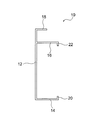
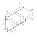
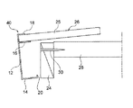
図1は、本発明に用いる棚施工用部材の第1実施形態を示す側面図、図2は、図1の棚施工用部材を用いて施工した本発明の棚を示す概略斜視図である。本例の棚施工用部材10は、適宜色彩が施された不透明な合成樹脂により一体成形されたものである。
(First embodiment of shelf construction member)
FIG. 1 is a side view showing a first embodiment of a shelf construction member used in the present invention, and FIG. 2 is a schematic perspective view showing a shelf of the present invention constructed using the shelf construction member of FIG. The
本例の棚施工用部材10において、12は長尺長方形の垂直板部、14は垂直板部12の下端から後方に突出した長尺長方形の下側水平板部、16は垂直板部12の上下方向中間部から後方に突出した長尺長方形の中間水平板部、18は垂直板部12の上端から後方に突出した長尺長方形の上側水平板部を示す。下側水平板部14と中間水平板部16との間の距離は前框24の高さとほぼ等しく、中間水平板部16と上側水平板部18との間の距離は棚板26の各四角板材25の厚さとほぼ等しい。
In the
また、下側水平板部14の後端には、上方に突出した長尺長方形の下側係止板20が形成されているとともに、中間水平板部16の後端には、下方に突出した長尺長方形の上側係止板22が形成されている。垂直板部12と下側係止板20との間の距離、および、垂直板部12と上側係止板22との間の距離は、いずれも前框24の厚さとほぼ等しい。
Further, a long rectangular
本例の棚施工用部材10を用いて、押入やクロゼットの中段棚、枕棚等の棚を施工する場合、図2に示すように、本例の棚施工用部材10と、上面および下面が平面状の四角板材からなる前框24と、上面および下面が平面状の複数の四角板材25からなる棚板26とを組み合わせる。なお、図2では、図示の便宜上、2枚の四角板材25を示しているが、四角板材25の枚数に限定はない。また、棚板26の四角板材25の上面には化粧紙(図示せず)が貼られている。
When using the
そして、棚を施工するに当たり、下側水平板部14と中間水平板部16との間に前框24全体を挿入し、中間水平板部16と上側水平板部18との間に棚板26の各四角板材25の前端部を挿入する。また、垂直板部12と下側係止板20との間に前框24の下端部を挿入し、垂直板部12と上側係止板22との間に前框24の上端部を挿入する。
In constructing the shelf, the
この場合、例えば下記(ア)〜(エ)の手順で棚を施工することができるが、棚の施工手順はこれらに限定されるものではない。
(ア)予め棚施工用部材10を取り付けた前框24および後受桟を押入内に固定し、次いで前框24および後受桟に棚板26の各四角板材25を固定した後、横受桟を押入内に固定する。
(イ)予め棚施工用部材10を取り付けた前框24、後受桟および横受桟を押入内に固定した後、前框24、後受桟および横受桟に棚板26の各四角板材25を固定する。
(ウ)前框24および後受桟を押入内に固定し、次いで前框24に棚施工用部材10を取り付けた後、前框24および後受桟に棚板26の各四角板材25を固定し、さらに横受桟を押入内に固定する。
(エ)前框24、後受桟および横受桟を押入内に固定し、次いで前框24に棚施工用部材10を取り付けた後、前框24、後受桟および横受桟に棚板26の各四角板材25を固定する。
In this case, for example, the shelf can be constructed by the following procedures (a) to (d), but the shelf construction procedure is not limited to these.
(A) The
(A) After fixing the
(C) After fixing the
(D) After fixing the
なお、(ウ)、(エ)のように前框24を押入内に固定してから前框24に棚施工用部材10を取り付ける場合、棚施工用部材10の後端部を開いて前框24に棚施工用部材10を押し込む。また、前框24と横受桟との間に上側係止板22が介在することを防止するために、上側係止板22の横受桟の端面に対向する部分を予め切除してもよい。
In addition, when attaching the
本例の棚施工用部材10の寸法に限定はなく、前框および棚板の寸法に応じて適宜設定することができるが、通常、垂直板部12の長さ(押入・クロゼットの間口に相当)は800〜3000mm、下側水平板部14と中間水平板部16との間の距離(前框の高さに相当)は40〜80mm、中間水平板部16と上側水平板部18との間の距離(棚板の厚さに相当)は5〜20mm、垂直板部12と下側係止板20との間の距離(前框の厚さに相当)は20〜30mm、垂直板部12と上側係止板22との間の距離(前框の厚さに相当)は20〜30mmとすることが適当である。
There is no limitation on the dimensions of the
本実施形態の棚施工用部材10は、下記の作用効果を奏する。
[1]前框24および棚板26として、上面および下面が平面状の四角板材からなるものを使用することができ、前框24および棚板26の両方に加工が不要であるため、前框24および棚板26の製造コストを安くすることができる。
[2]前框24の前面を合成樹脂からなる棚施工用部材10で覆っているため、前框24の前面に凹みや傷が付きにくい。
[3]前框24の前面を不透明の合成樹脂からなる棚施工用部材10で覆っているため、棚施工用部材10の表面から下地(前框24の表面)が透けて見えたり、棚施工用部材10の表面に下地(同前)の凹凸が現れたりすることがない。
[4]上記のように棚施工用部材10の表面から下地が透けて見えたり、棚施工用部材10の表面に下地の凹凸が現れたりすることがないため、前框24として表面品質が悪いものも使用することができる。
[5]枕棚のように棚板26の取り付け位置が目線より高くなる場合などにおいて、棚板26の四角板材25の上面のみに化粧紙が貼られているときに、棚板26の四角板材25を上下反転させて化粧紙が下から見えるように施工することができる。これは、棚板26が上面および下面が平面状の複数の四角板材25からなり、図10に示した従来例のように、棚板および前框の加工部分同士を係合させる必要がないためである。
[6]予め棚施工用部材10を取り付けた前框24を押入内に固定したり、前框24を押入内に固定してから前框24に棚施工用部材10を取り付けたりすることができるなど、棚の施工方法の自由度が増加する。
The
[1] Since the front and
[2] Since the front surface of the
[3] Since the front surface of the
[4] As described above, since the base is not seen through from the surface of the
[5] When the mounting position of the
[6] The
(棚施工用部材の第2実施形態)
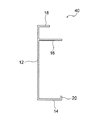
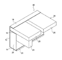
図3は、本発明に用いる棚施工用部材の第2実施形態を示す側面図、図4は、図3の棚施工用部材を用いて施工した本発明の棚を示す概略斜視図である。本例の棚施工用部材40は、第1実施形態の棚施工用部材10において、上側係止板22を形成していないものである。その他の構成は第1実施形態の棚施工用部材10と同様であるため、図3において図1と同一構成の部分には、同一の参照符号を付してその説明を省略する。
(Second embodiment of shelf construction member)
FIG. 3 is a side view showing a second embodiment of the shelf construction member used in the present invention, and FIG. 4 is a schematic perspective view showing the shelf of the present invention constructed using the shelf construction member of FIG. The
本例の棚施工用部材40を用いて棚を施工するに当たっては、図4に示すように、下側水平板部14と中間水平板部16との間に前框24全体を挿入し、中間水平板部16と上側水平板部18との間に棚板26の各四角板材25の前端部を挿入する。また、垂直板部12と下側係止板20との間に前框24の下端部を挿入する。なお、図4において符号28は横受桟を示す。
In constructing a shelf using the
本例の棚施工用部材40を用いて、押入やクロゼットの中段棚、枕棚等の棚を施工する場合、前述した(ア)〜(エ)の手順で棚を施工することができるが、第1実施形態と同様に、棚の施工手順はこれらに限定されるものではない。
Using the
また、前述した手順(エ)、すなわち、前框24、後受桟および横受桟28を押入内に固定し、次いで前框24に棚施工用部材40を取り付けた後、前框24、後受桟および横受桟に棚板26の四角板材25を固定する手順を採用した場合、上側係止板22がないため、図5に示すように、棚板26の四角板材25に取り付けた棚施工用部材40を斜め前方から滑らすようにして前框24に取り付けることができ、棚施工用部材40の前框24への取り付け作業が容易である。また、棚施工用部材40の表面から下地が透けて見えることがないため、前框24を横受桟28にビス30を用いて固定することができ、前框24の固定作業が容易である。
In addition, the above-described procedure (d), that is, after the
なお、本発明に用いる棚施工用部材の形状・構造は、前述した実施形態に限定されるものではなく、必要に応じて種々の変更が可能である。例えば、下側係止板20および上側係止板22をいずれも形成しなくてもよく、上側係止板22のみを形成してもよい。また、下側水平板部14、中間水平板部16、上側水平板部18、下側係止板20および上側係止板22の形状は長尺長方形に限定されるものではなく、他の適宜形状とすることができる。
In addition, the shape and structure of the member for shelf construction used for this invention are not limited to embodiment mentioned above, A various change is possible as needed. For example, neither the
(棚の第1実施形態)
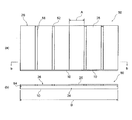
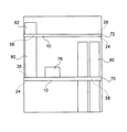
図6は、本発明の棚の第1実施形態を示すもので、(a)は平面図、(b)は(a)図のb−b線に沿った断面図である。
(First embodiment of the shelf)
FIG. 6: shows 1st Embodiment of the shelf of this invention, (a) is a top view, (b) is sectional drawing along the bb line of (a) figure.
本例の棚50は、図1、図2に示した棚施工用部材10と、前框24と、棚板26とを備えた棚である。図6において、図1、図2と同一構成の部分には、同一の参照符号を付してその説明を省略する。なお、図6では、棚施工用部材10の下側係止板および上側係止板の図示を省略してある。また、図6において、52は後受桟、54は横受桟を示す。
The
本例の棚50において、棚板26は、6枚の四角板材25からなる。具体的には、棚板26の各四角板材25の横方向の長さAは約300mm、横方向の長さの合計C(図示なし)は約1800mm、前後方向の長さは約900mm、厚さは約15mmである。また、棚施工用部材10の横方向の長さBは約2000mmである。したがって、A:B=1:2〜1:10の範囲にあり、C:B=1:0.5〜1:1.5の範囲にある。
In the
本例では、四角板材25を棚施工用部材10の横方向においてほぼ均等に配置して棚板26を構成している。ただし、所定の四角板材25間の4箇所に幅(横方向の長さ)が約45mmの隙間56を設けることにより、棚板26の通気性を良くしている。
In this example, the
本例において、棚板26の各四角板材25は、棚施工用部材10に接着剤等で固定してもよく、接着剤等で固定せずに、棚施工用部材10に沿って移動させたり、棚施工用部材10から取り外したりすることができるようにしてもよい。
In this example, each
(棚の第2実施形態)
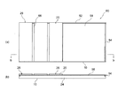
図7は、本発明の棚の第2実施形態を示すもので、(a)は平面図、(b)は(a)図b−b線に沿った断面図である。
(Second embodiment of the shelf)
FIG. 7: shows 2nd Embodiment of the shelf of this invention, (a) is a top view, (b) is sectional drawing along the (a) figure bb line.
本例の棚60は、本例の棚50は、前述した本発明の棚の第1実施形態と同じ棚施工用部材10、前框24および棚板26を備えた棚であり、第1実施形態とは異なる態様で棚板26を配置したものである。
The
本例では、棚施工用部材10の横方向の長さの半分の部分に四角板材25を2枚重ねて配置して棚板26を形成することにより、棚板26に重量物を載せることができるようにしてある。また、棚施工用部材10の横方向の長さのもう一方の半分の部分に四角板材25を配置していない吹き抜け部58を設けることにより、この吹き抜け部58を利用して長物を収納できるようにしてある。さらに、所定の四角板材25間の2箇所に幅が約45mmの隙間56を設けることにより、棚板26の通気性を良くしている。なお、重ねた2枚の四角板材25は、接着剤等で互いに固定してもよく、互いに固定しなくてもよい。
In this example, it is possible to place a heavy article on the
(棚の第3実施形態)
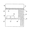
図8は、本発明の棚の第3実施形態を示す模式的正面図である。図8において、70は中段棚、72は枕棚、74はハンガーパイプを示す。上記中段棚70および枕棚72は、いずれも、前述した本発明の棚の第1実施形態と同じ棚施工用部材10、前框24および棚板26を備えた棚であり、第1実施形態とは異なる態様で棚板26を配置したものである。ただし、枕棚72の前後方向の長さは約600mmである。
(Third embodiment of the shelf)
FIG. 8 is a schematic front view showing a third embodiment of the shelf of the present invention. In FIG. 8, 70 is a middle shelf, 72 is a pillow shelf, and 74 is a hanger pipe. Each of the
本例では、中段棚70の一部に棚板26を形成し、この棚板26に物品76を載せることができるようにしてある。また、中段棚70の一部に棚板26を配置していない吹き抜け部58を設けることにより、この吹き抜け部58を利用してハンガーパイプ74にロングコート78等の長物を吊すことができるようにしてある。
In this example, the
また、図示していないが、中段棚70および枕棚72では、棚板26に前記実施形態と同様の隙間を設けることにより、棚板26の通気性を良くしている。
Further, although not shown, in the
(棚の第4実施形態)
図9は、本発明の棚の第4実施形態を示す模式的正面図である。図9において、70は中段棚、72は枕棚を示す。上記中段棚70および枕棚72は、いずれも、前述した本発明の棚の第1実施形態と同じ棚施工用部材10、前框24および棚板26を備えた棚であり、第1実施形態とは異なる態様で棚板26を配置したものである。ただし、枕棚72の前後方向の長さは約600mmである。
(4th Embodiment of a shelf)
FIG. 9 is a schematic front view showing a fourth embodiment of the shelf of the present invention. In FIG. 9,
本例では、中段棚70の一部に棚板26を形成し、この棚板26に物品76を載せることができるようにしてある。また、中段棚70の一部に棚板26を配置していない吹き抜け部58を設けることにより、この吹き抜け部58を利用して長物80を収納できるようにしてある。さらに、枕棚72の一部に棚板26を配置していない吹き抜け部58を設けることにより、この吹き抜け部58を利用して中段棚70に長物80を載置できるようにしてある。
In this example, the
また、図示していないが、本例の中段棚70および枕棚72では、棚板26に前記実施形態と同様の隙間を設けることにより、棚板26の通気性を良くしている。
Moreover, although not shown in figure, in the
上述した本例の棚50、棚60、中段棚70および枕棚72は、いずれも、棚板26の配置態様の自由度を有するものである。なお、本発明の棚における棚板の配置態様は、前述した実施形態に限定されるものではなく、その他の種々の態様で棚板を配置することができる。
All of the
10 棚施工用部材
12 垂直板部
14 下側水平板部
16 中間水平板部
18 上側水平板部
20 下側係止板
22 上側係止板
24 前框
25 四角板材
26 棚板
50 棚
60 棚
70 中段棚
72 枕棚
DESCRIPTION OF
Claims (10)
前記棚施工用部材は、四角形の垂直板部と、前記垂直板部の下端から後方に突出した下側水平板部と、前記垂直板部の上下方向中間部から後方に突出した中間水平板部と、前記垂直板部の上端から後方に突出した上側水平板部とを有し、前記下側水平板部と前記中間水平板部との間の距離が前記前框の高さとほぼ等しく、前記中間水平板部と前記上側水平板部との間の距離が前記棚板の厚さとほぼ等しいものであり、
前記前框は、上面および下面が平面状で、横方向の長さが前記棚施工用部材の横方向の長さとほぼ等しい四角板材からなるものであり、
前記棚板は、上面および下面が平面状で、横方向の長さが前記棚施工用部材の横方向の長さより短い複数の四角板材からなるものであり、
前記下側水平板部と前記中間水平板部との間に前記前框が挿入され、前記中間水平板部と前記上側水平板部との間に前記棚板の複数の四角板材の一部または全部の前端部が挿入されていることを特徴とする棚。 It is a shelf provided with a shelf construction member, an outpost, and a shelf board,
The shelf construction member includes a rectangular vertical plate portion, a lower horizontal plate portion protruding rearward from a lower end of the vertical plate portion, and an intermediate horizontal plate portion protruding rearward from an intermediate portion in the vertical direction of the vertical plate portion. And an upper horizontal plate portion that protrudes rearward from the upper end of the vertical plate portion, and the distance between the lower horizontal plate portion and the intermediate horizontal plate portion is substantially equal to the height of the forehead, The distance between the intermediate horizontal plate portion and the upper horizontal plate portion is substantially equal to the thickness of the shelf plate,
The front wing is a flat plate having an upper surface and a lower surface, and is composed of a square plate material whose lateral length is substantially equal to the lateral length of the shelf construction member,
The shelf board is composed of a plurality of square plate materials whose upper and lower surfaces are planar and whose lateral length is shorter than the lateral length of the shelf construction member,
The front wing is inserted between the lower horizontal plate portion and the intermediate horizontal plate portion, and a part of the plurality of square plate members of the shelf plate between the intermediate horizontal plate portion and the upper horizontal plate portion or A shelf characterized in that all front ends are inserted.
前記棚施工用部材は、四角形の垂直板部と、前記垂直板部の下端から後方に突出した下側水平板部と、前記垂直板部の上下方向中間部から後方に突出した中間水平板部と、前記垂直板部の上端から後方に突出した上側水平板部とを有し、前記下側水平板部と前記中間水平板部との間の距離が前記前框の高さとほぼ等しく、前記中間水平板部と前記上側水平板部との間の距離が前記棚板の厚さとほぼ等しいものであり、
前記前框は、上面および下面が平面状で、横方向の長さが前記棚施工用部材の横方向の長さとほぼ等しい四角板材からなるものであり、
前記棚板は、上面および下面が平面状で、横方向の長さが前記棚施工用部材の横方向の長さより短い複数の四角板材からなるものであり、
前記下側水平板部と前記中間水平板部との間に前記前框を挿入し、前記中間水平板部と前記上側水平板部との間に前記棚板の複数の四角板材の一部または全部の前端部を挿入することを特徴とする棚施工用セット。 It is a set for shelf construction provided with a member for shelf construction, an outpost, and a shelf board,
The shelf construction member includes a rectangular vertical plate portion, a lower horizontal plate portion protruding rearward from a lower end of the vertical plate portion, and an intermediate horizontal plate portion protruding rearward from an intermediate portion in the vertical direction of the vertical plate portion. And an upper horizontal plate portion that protrudes rearward from the upper end of the vertical plate portion, and the distance between the lower horizontal plate portion and the intermediate horizontal plate portion is substantially equal to the height of the forehead, The distance between the intermediate horizontal plate portion and the upper horizontal plate portion is substantially equal to the thickness of the shelf plate,
The front wing is a flat plate having an upper surface and a lower surface, and is composed of a square plate material whose lateral length is substantially equal to the lateral length of the shelf construction member,
The shelf board is composed of a plurality of square plate materials whose upper and lower surfaces are planar and whose lateral length is shorter than the lateral length of the shelf construction member,
A part of the plurality of square plate members of the shelf plate is inserted between the lower horizontal plate portion and the intermediate horizontal plate portion, and between the intermediate horizontal plate portion and the upper horizontal plate portion, or A shelf construction set characterized by inserting all front end portions.
Priority Applications (1)
| Application Number | Priority Date | Filing Date | Title |
|---|---|---|---|
| JP2012240422A JP2014088739A (en) | 2012-10-31 | 2012-10-31 | Shelf and set for execution of shelf |
Applications Claiming Priority (1)
| Application Number | Priority Date | Filing Date | Title |
|---|---|---|---|
| JP2012240422A JP2014088739A (en) | 2012-10-31 | 2012-10-31 | Shelf and set for execution of shelf |
Publications (1)
| Publication Number | Publication Date |
|---|---|
| JP2014088739A true JP2014088739A (en) | 2014-05-15 |
Family
ID=50790838
Family Applications (1)
| Application Number | Title | Priority Date | Filing Date |
|---|---|---|---|
| JP2012240422A Pending JP2014088739A (en) | 2012-10-31 | 2012-10-31 | Shelf and set for execution of shelf |
Country Status (1)
| Country | Link |
|---|---|
| JP (1) | JP2014088739A (en) |
Citations (7)
| Publication number | Priority date | Publication date | Assignee | Title |
|---|---|---|---|---|
| JPS565734U (en) * | 1979-06-25 | 1981-01-19 | ||
| JPS5938337U (en) * | 1982-09-03 | 1984-03-10 | 株式会社長谷川工務店 | closet shelf |
| JPS59179939U (en) * | 1983-05-18 | 1984-12-01 | フクビ化学工業株式会社 | front stile of closet shelf |
| JP3077686B2 (en) * | 1998-12-16 | 2000-08-14 | 日新電機株式会社 | Circuit breaker circuit inspection device |
| JP3079798B2 (en) * | 1992-09-04 | 2000-08-21 | トヨタ自動車株式会社 | Beam welding method |
| JP2004263503A (en) * | 2003-03-04 | 2004-09-24 | Rosuko Kk | Built-up type closet and construction method for it |
| JP2008038533A (en) * | 2006-08-09 | 2008-02-21 | Wood One:Kk | Installation shelf and installation shelf |
-
2012
- 2012-10-31 JP JP2012240422A patent/JP2014088739A/en active Pending
Patent Citations (7)
| Publication number | Priority date | Publication date | Assignee | Title |
|---|---|---|---|---|
| JPS565734U (en) * | 1979-06-25 | 1981-01-19 | ||
| JPS5938337U (en) * | 1982-09-03 | 1984-03-10 | 株式会社長谷川工務店 | closet shelf |
| JPS59179939U (en) * | 1983-05-18 | 1984-12-01 | フクビ化学工業株式会社 | front stile of closet shelf |
| JP3079798B2 (en) * | 1992-09-04 | 2000-08-21 | トヨタ自動車株式会社 | Beam welding method |
| JP3077686B2 (en) * | 1998-12-16 | 2000-08-14 | 日新電機株式会社 | Circuit breaker circuit inspection device |
| JP2004263503A (en) * | 2003-03-04 | 2004-09-24 | Rosuko Kk | Built-up type closet and construction method for it |
| JP2008038533A (en) * | 2006-08-09 | 2008-02-21 | Wood One:Kk | Installation shelf and installation shelf |
Similar Documents
| Publication | Publication Date | Title |
|---|---|---|
| US11517130B2 (en) | Frame apparatus | |
| US20110011855A1 (en) | Prefabricated recipient box | |
| US20140150614A1 (en) | Recessed reveal wall panel system | |
| US12279706B2 (en) | Frame apparatus | |
| US10188232B2 (en) | Decorative article with receiving member | |
| JP2014088739A (en) | Shelf and set for execution of shelf | |
| JP4117329B2 (en) | Long material for hanging ceiling boards | |
| JP2018104950A (en) | Mounting method of storage unit | |
| JP2014047490A (en) | Shelf construction member and shelf construction set | |
| CN212015045U (en) | Shelf and cloakroom | |
| EP2840937B1 (en) | System for displaying items | |
| KR100982305B1 (en) | Fixed frame with mirror fixtures and fixtures | |
| JP2014005680A (en) | Members for constructing shelf and set for constructing shelf | |
| JP5046270B2 (en) | Panel and partition device | |
| JPH053091Y2 (en) | ||
| JP6807731B2 (en) | Fixed structure of shelf board and construction method of shelf board | |
| JP4916142B2 (en) | Storage device | |
| JP4918837B2 (en) | Wall structure | |
| US5876004A (en) | Furniture supporting system | |
| CN212465584U (en) | A kind of anti-deformation picture frame strip and its picture frame | |
| JP6973760B1 (en) | Wall mount | |
| JP7670952B2 (en) | Fixture structure | |
| JP7746663B2 (en) | Fixture structure | |
| JP6320352B2 (en) | Shelf board structure | |
| JP2018108418A (en) | Storage box and storage box manufacturing method |
Legal Events
| Date | Code | Title | Description |
|---|---|---|---|
| A621 | Written request for application examination |
Free format text: JAPANESE INTERMEDIATE CODE: A621 Effective date: 20151030 |
|
| A977 | Report on retrieval |
Free format text: JAPANESE INTERMEDIATE CODE: A971007 Effective date: 20160824 |
|
| A131 | Notification of reasons for refusal |
Free format text: JAPANESE INTERMEDIATE CODE: A131 Effective date: 20160830 |
|
| A02 | Decision of refusal |
Free format text: JAPANESE INTERMEDIATE CODE: A02 Effective date: 20170307 |