JP2014088731A - Wiring pulling-in device - Google Patents
Wiring pulling-in device Download PDFInfo
- Publication number
- JP2014088731A JP2014088731A JP2012240161A JP2012240161A JP2014088731A JP 2014088731 A JP2014088731 A JP 2014088731A JP 2012240161 A JP2012240161 A JP 2012240161A JP 2012240161 A JP2012240161 A JP 2012240161A JP 2014088731 A JP2014088731 A JP 2014088731A
- Authority
- JP
- Japan
- Prior art keywords
- wiring
- base
- cover
- wiring support
- support portion
- Prior art date
- Legal status (The legal status is an assumption and is not a legal conclusion. Google has not performed a legal analysis and makes no representation as to the accuracy of the status listed.)
- Granted
Links
Images
Landscapes
- Roof Covering Using Slabs Or Stiff Sheets (AREA)
Abstract
【解決手段】本発明の配線引込装置は、屋外の配線を支持して開口部から屋内へ導入するもので、その支持手段は発泡性弾性樹脂材からなる配線支持部が基台とカバーに各々相互に圧縮するように配置され、それらにより配線を狭持して支持するものである。また、第一の配線支持部と第二の配線支持部とに高低差を設けている。
【効果】発泡性弾性樹脂材により各々を圧縮するように挟持すること、2つの配線支持部が高低差を設けることで、雨水等が侵入し難くなり、高い止水性を発揮する。また、カバーの装着により簡単に支持することができ、換気棟と連結して一体性があるため、外観上も優れる。
【選択図】図8A wiring lead-in device of the present invention supports outdoor wiring and introduces it into an indoor through an opening, and the supporting means includes wiring support portions made of a foamed elastic resin material on a base and a cover, respectively. They are arranged so as to compress each other, and support the wiring by sandwiching them. Further, a height difference is provided between the first wiring support portion and the second wiring support portion.
[Effect] Each of the two wiring support portions is sandwiched so as to be compressed by the foaming elastic resin material, and rainwater or the like is difficult to invade by providing a height difference between the two wiring support portions, thereby exhibiting high water stoppage. Moreover, it can be easily supported by attaching a cover, and since it is integrated with the ventilation building, it is excellent in appearance.
[Selection] Figure 8
Description
本発明は、屋根の頂頭部を開口して換気する換気棟と連続して設置する配線引込装置であって、高い止水性を有し、太陽電池パネル等の屋根上配置機器の配線を屋内に引き込むための装置に関する。 The present invention is a wiring lead-in device that is installed continuously with a ventilation building that opens and ventilates the top of the roof, has a high water-stopping property, and the wiring of roof-arranged equipment such as solar cell panels indoors It relates to a device for retracting.
太陽光発電パネルの配線を屋内に引き込むための引き込み構造において、ベース板に開口を形成する配線の引き込み構造は存在した。
(例えば特許文献1参照)
また、換気のための開口部と配線の引き込み口を同一の開口部とするものも存在した。
(例えば特許文献2参照)
In the lead-in structure for drawing the wiring of the photovoltaic power generation panel indoors, there is a lead-in structure of the wiring that forms an opening in the base plate.
(For example, see Patent Document 1)
In addition, there is one in which the opening for ventilation and the wiring inlet are the same opening.
(For example, see Patent Document 2)
特許文献1に記載の発明は、太陽光パネルの配線の引き込み口が防水効果を有するように引き込むものであり、換気棟を併設した場合に別途開口部を形成する必要があり、施工に手間がかかった。
また、特許文献2に記載の発明は、換気棟の開口部を配線の引き込み口と兼ねるもので施工の手間は省略できるが、換気棟の内方まで太陽光パネルを設置しなければならず、太陽光パネル及び換気棟の施工が簡単ではなく、高い止水性を有するものではなかった。
In the invention described in
Moreover, although the invention of
そこで、高い止水性を有し、施工の手間がかからず、簡単に太陽光パネル等の屋根上配置機器の配線を引き込むことができる配線引込装置が求められていた。 Therefore, there has been a demand for a wiring drawing-in device that has high water-stopping properties, does not require labor for construction, and can easily pull in wiring of equipment arranged on the roof such as a solar panel.
そこで、本発明の配線引込装置は、屋根上配置機器の配線を開口部から屋内に引き込むためのものであって、少なくとも基台と、カバーとからなり、前記基台は、配線を下側から支持するものであって、発泡性弾性樹脂材からなる基台配線支持部を有し、前記カバーは、配線を上側から支持するものであって、発泡性弾性樹脂材からなるカバー配線支持部を有し、前記基台配線支持部と前記カバー配線支持部は、カバーを基台に取り付けて配線を支持したときに、互いに圧縮し、前記配線を狭持して支持することを特徴とするものである。 Therefore, the wiring lead-in device of the present invention is for drawing the wiring of the arrangement device on the roof indoors from the opening, and is composed of at least a base and a cover, and the base has the wiring from the lower side. A support wiring support portion made of an expandable elastic resin material, the cover supporting the wiring from above, and a cover wiring support portion made of an expandable elastic resin material; The base wiring support part and the cover wiring support part are compressed to each other when the cover is attached to the base to support the wiring, and the wiring is sandwiched and supported. It is.
また、前記開口部は、勾配屋根の屋根頂部をその長手方向に開口する棟換気用の開口部であって、前記基台は、前記開口部の長手方向に沿って配置される換気棟と連続して配置されたことが好ましい。 The opening is an opening for building ventilation that opens a roof top of a sloped roof in the longitudinal direction thereof, and the base is continuous with a ventilation building that is arranged along the longitudinal direction of the opening. Are preferably arranged.
また、前記基台配線支持部は、前記基台の開口部分側の第一の基台配線支持部と、軒先側の第二の基台配線支持部とからなり、第一の基台配線支持部は、基台の開口部分側の端辺を延長して上側で折り返した折り返し片の上面に取り付けられたことが好ましい。 In addition, the base wiring support section includes a first base wiring support section on the opening portion side of the base and a second base wiring support section on the eaves side, and the first base wiring support section It is preferable that the part is attached to the upper surface of the folded piece which is extended on the upper side by extending the end side on the opening portion side of the base.
また、前記カバー配線支持部は、前記第一の基台配線支持部に対応する第一のカバー配線支持部と、前記第二の基台配線支持部に対応する第二のカバー配線支持部とからなり、前記第二のカバー配線支持部は、カバーの裏面から台上に配置されたことが好ましい。 The cover wiring support portion includes a first cover wiring support portion corresponding to the first base wiring support portion, and a second cover wiring support portion corresponding to the second base wiring support portion. It is preferable that the second cover wiring support portion is disposed on the table from the back surface of the cover.
また、前記配線引込装置は外観上換気棟とほぼ同じ形態であって、換気棟及びその他の屋根部材と連結するための連結手段を有することが好ましい。 Moreover, it is preferable that the said wiring drawing-in apparatus is a form substantially the same as a ventilation building in an external appearance, and has a connection means for connecting with a ventilation building and another roof member.
請求項1に記載の発明により、配線を屋内に導入することができるとともに、弾性のある発泡性樹脂材により配線を狭持して支持することにより、配線を傷めずに支持することができるのみならず、配線を伝って外部の雨水等の流入を遮断することができ、止水性が高い配線引込装置を提供することができる。 According to the first aspect of the present invention, the wiring can be introduced indoors and can be supported without damaging the wiring by sandwiching and supporting the wiring with an elastic foamable resin material. In addition, it is possible to block the inflow of external rainwater and the like through the wiring, and to provide a wiring drawing-in device having a high water-stopping property.
請求項2に記載の発明により、弾性のある発泡性樹脂材が互いに圧縮するように配置されていることから、外部の雨水等が発泡性樹脂材に染み込んで屋内に流入することを防止することができ、更に高い止水性を有する配線引込装置を提供することができる。 According to the second aspect of the present invention, since the elastic foamable resin materials are arranged so as to compress each other, it is possible to prevent external rainwater or the like from infiltrating into the foamable resin material and flowing into the room. Thus, it is possible to provide a wiring drawing device having a higher water-stopping property.
請求項3に記載の発明により、基台の配線支持部が開口部分側と軒先側との二か所に配置され、開口部側の第一の配線支持部が折り返し片により高い位置に配置されていることから、折り返し片が水切り材としての効果を発揮するため、更に高い止水性を有する配線引込装置を提供することができる。 According to the third aspect of the present invention, the wiring support portions of the base are arranged at two locations, the opening portion side and the eaves side, and the first wiring support portion on the opening portion side is arranged at a higher position by the folded piece. Therefore, since the folded piece exhibits an effect as a draining material, it is possible to provide a wiring drawing device having a higher water-stopping property.
請求項4に記載の発明により、第二の基台配線支持部に相当する位置の第二のカバー配線支持部は、カバーの裏面から台上に配置され、第一のカバー配線支持部よりも高い位置に配置されている。これにより、第一の基台配線支持部及び第一のカバー配線支持部により支持される位置と、第二の基台配線支持部及び第二のカバー配線支持部により支持される位置との間に高低差を設けることができ、外部の雨水等の流入を防止し、更に高い止水性を有する配線引込装置を提供することができる。
According to the invention of
請求項5に記載の発明により、換気棟と連結することができ、換気棟と外観上ほぼ同じ形態をとるため、両者を連結して配置したとき、外観上優れた配線引込装置を提供することができる。 According to the fifth aspect of the present invention, it is possible to connect to a ventilation building, and since it takes almost the same form as the ventilation building, when the both are connected and arranged, a wiring drawing device excellent in appearance is provided. Can do.
本発明の実施の一例を図面に沿って説明する。
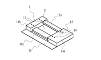
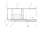
図1ないし図5は、本発明の第一実施例にかかる配線引込装置であって、片流れの屋根9に取り付けるものである。図1は、配線引込装置1に用いる基台2の一例を示す。配線引込装置1は、基台2とカバー3からなるが、カバー3を取り付けるためにカバー台座4を使用する。この配線引込装置1により、屋根9上の太陽光パネルなどの屋根上配置機器の配線5を支持しつつ、屋根9の開口部7を通って屋内に引き込むことができる。屋根の開口部7は、換気棟8(図5)を用いた場合に屋根の頂頭部を開口する部分を利用する。
An embodiment of the present invention will be described with reference to the drawings.
FIGS. 1 to 5 show a wiring drawing apparatus according to a first embodiment of the present invention, which is attached to a single-flow roof 9. FIG. 1 shows an example of a
基台2は、平板状の底板11と、第一の基台配線支持部13aと、第二の基台配線支持部13bと、カバー取付台14a、14bとからなる。
基台2の底板11の開口部7側(図1の右上側)には、その端辺を延長して折り返して片持ち状にした折り返し片12が形成される。折り返し片12の折り返した上面には緩衝材を配置して第一の基台配線支持部13aを形成する。
The
On the opening 7 side (upper right side in FIG. 1) of the
また、底板11の上面であって、第一の基台配線支持部13aの軒先側(図1の左手前側)に、さらに緩衝材を配置して第二の基台配線支持部13bを形成する。折り返し片12は、底板11の端辺を延長し、直角以上の角度で折曲し、その後、さらに軒方向(図1の左手前方向)に向けて折曲したものであるため、第一の基台配線支持部13aは第二の基台配線支持部13bよりも高い位置に配置されている。
Further, a buffer material is further disposed on the eaves side of the first base
緩衝材は、弾性を有する発泡性の樹脂材である。具体的には、エチレンプロピレンゴム材(EPDM)が好ましいが、弾性を有する発泡性の樹脂材であれば、ウレタン系樹脂材やシリコン系樹脂材であっても良い。底板11は、鋼板を成形することにより作ることができるが、屋外に設置するため、高い防食性を備えたガルバリウム鋼板を用いることが好ましい。しかし、ガルバリウム鋼板のみに限定されるものではなく、通常の亜鉛メッキ鋼板やアルミニウム鋼板など、その他の材質のものであっても良い。
The buffer material is a foamable resin material having elasticity. Specifically, an ethylene propylene rubber material (EPDM) is preferable, but a urethane resin material or a silicon resin material may be used as long as it is a foamable resin material having elasticity. The
第二の基台配線支持部13bよりも軒先側は、先述のカバー取付台14a、14bなどが配置されておらず、底板11の幅方向(図1の左右方向)全体に渡って配線導入部15として利用することができる。配線導入部15の軒側の端辺は、使用者が怪我をしないように、下側に折り返してある。
The above-described
底板11の両側方(図1の右手前側と左奥側)には、カバー取付台14a、14bが配置されている。カバー取付台14a、14bは底板11から台状に隆起させたもので、その高さは第一の基台配線支持部13aよりも高い。カバー取付台14a、14bの高さは平板状のカバー3、カバー台座4を取り付けたときに、換気棟8と同じ高さとなるようにする。なお、カバー取付台14a、14bにはカバー3、カバー台座4を取り付けるためのネジ孔16、16が形成されている。
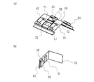
図2(a)に示すように、基台2にはカバー台座4を取り付ける。図1に示すように、この基台2における2つのカバー取付台14a、14bのうち、手前側の第一のカバー取付台14aを奥側の第二のカバー取付台14bよりも、幅方向(図1、図2(a)の左右方向)に延長されていて、底板11、配線導入部15も第一のカバー取付台14aの大きさに合わせて、延長されている。この延長された部分は、換気棟8や他の配線引込装置1の連結部24と連結するための部分となる。
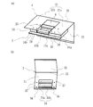
As shown in FIG. 2A, a
図2(a)に示すように、カバー台座4は、平板部21と垂直部22とからなり、垂直部22は、平板部21の端辺から垂直方向に折曲25して形成されている。平板部21は、基台2の底板11と同じく平板状のものである。平板部21は、第一の平板部21aと第二の平板部21bの間を、軒側から所定の部分を切除してあるため、平面略コの字状になっている。この切除部分23は、カバー台座4を基台2に取り付けた場合、基台2の第一の基台配線支持部13aと第二の基台配線支持部13b及び通路6が、露出するように切除されている。
As shown in FIG. 2A, the
カバー台座4の軒側(図2(a)の手前側)の端辺は、カバー取付台14a、14bの軒側の端辺と同じ位置となるように形成されている。カバー台座4の第一の平板部21aは、延長された第一のカバー取付台14aと同じ幅を有し、これと同じ大きさの第二の平板部21bが第二のカバー取付台14bに取り付けられる。そのため、第二の平板部21bの下側の一部にのみ第二のカバー取付台14bが位置することになり、他の部分は空洞になっている。この空洞部分が換気棟8や他の配線引込装置1と連結するための空洞連結部24となる。
The edge of the
また、図2(a)及び図4に示すように、カバー台座4の平板部21の奥行きは、基台2の奥行きよりも長く形成され、その部分が垂直方向に折曲された垂直部22となっている。したがって、この基台2の奥端面と垂直部22までの間には所定の間隔が空いている。この部分に配線5が導入されて屋内に達するまでの通路6となる。
As shown in FIGS. 2A and 4, the depth of the
平板部21には、第一のカバー取付台14a、第二のカバー取付台14bに形成されているネジ孔16、16に対応する位置にネジ孔26、26が形成され、これらにネジを通すことにより、カバー台座4を基台2に取り付けて固定することができる。
Screw holes 26 and 26 are formed in the
図2(b)に示すように、カバー3は、平板部31の端辺から垂直方向に折曲33して形成される垂直部32とからなる。この平板部31をカバー台座4の切除部分23を覆うように取り付けると、カバー3の折曲部33、垂直部32がカバー台座4の折曲部25、垂直部22に重なる。
As shown in FIG. 2B, the
平板部31は、カバー台座4の平板部21の切除部分23よりも若干大きく形成されている。平板部31が切除部分23を覆うようにカバー3をカバー台座4に取り付けると、切除部分23の周囲の第一の平板部21a、第二の平板部22bに、平板部31の周縁が重なり、切除部分23を上方から覆うことができる。この状態で、前記ネジ孔16、26とこれらに対応して形成されているネジ孔37、37とにネジを通すことによりカバー3をカバー台座4に固定する。
The
また、平板部31の軒先側(図2(b)の下側)を垂直方向に折曲して遮断壁36が形成されている。この遮断壁の高さは第一のカバー取付台14a、第二のカバー取付台14bの半分程度である。このため、カバー3を基台2に取り付けたとき、第二の基台配線支持部13bに配線5を挿入し得る配線開口部10を上方から一部遮断することができ、雨水の浸入を遮断できる。つまり、図3に示すように、この遮断壁36に覆われない部分は、配線5が挿通するための配線開口部10となる。
Further, a blocking
図2(b)に示すように、カバー3の裏面、すなわち平板部31の裏面には、取付時に基台2の第一の基台配線支持部13a、第二の基台配線支持部13bに相当する位置に、第一のカバー配線支持部34a、第二のカバー配線支持部34bが配置される。これら第一のカバー配線支持部34a、第二のカバー配線支持部34bは、緩衝材を配置することにより形成され、この緩衝材は基台の配線支持部13a、13bと同じく、弾性のある発泡性樹脂材からなるものとすることができる。
As shown in FIG. 2B, the back surface of the
また、平板部31の裏面には台35が形成され、その台上に第二のカバー配線支持部34bが配置されている。そのため、図2(b)では、第一のカバー配線支持部34aに比して第二のカバー配線支持部34bが高い位置に配置されることになる。これにより、第二の基台配線支持部13bは第一の基台配線支持部13aよりも低い位置に配置されることになり、第二のカバー配線支持部34bは、この第二の基台配線支持部13bに接触し、お互いを圧縮することができる。
Further, a
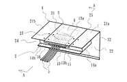
基台2の配線開口部10に配線5を挿通し、カバー台座4、カバー3を取り付けた状態を図3、図4に示す。カバー3を取り付けた状態で遮断壁36の下方となる配線開口部10から引き入れられた配線5は、第二の基台配線支持部13bと第二のカバー配線支持部34bに挟持され、その後、第一の基台配線支持部13a、第一のカバー配線支持部34aに挟持されて支持され、通路6を通り、屋根を開口した開口部7から屋内に引き入れられる。
3 and 4 show a state where the
図4に示すように、底板11に、折り返し片12が形成され、第一の基台配線支持部13aは、底板11よりも高いところに位置する。これにより、雨水などが配線引込装置1の配線開口部10から流入したとしても、この折り返し片12が水切りの役割を果たし、開口部7へ流入しない。
As shown in FIG. 4, the folded
また、第二のカバー配線支持部34bは、平板部31から台35を設けて配置されていることから、配線引込装置1に引き込まれた配線5は、第二の基台配線支持部13bと第二のカバー配線支持部34bによりいったん基台2の底板11付近で挟持され、その後、折り返し片12により基台2の底板11よりも高い位置で第一の基台配線支持部13aと第一のカバー配線支持部34aにより支持される。そのため、配線5はいったん支持された後に、底板11から高い位置で支持されることになり、配線を伝って雨水が流入したとしても、この高低差により雨水の浸入を防止することができる。
Moreover, since the 2nd cover
基台配線支持部13a、13bとカバー配線支持部34a、34bは、お互いを圧縮している。配線5を挟持する部分では、配線5を挟み込んでいるので、各々の緩衝材の高さが支持する前の状態から5分の1程度になるまで圧縮している。また、図示しないが、配線5を挟み込んでいない部分では、各々の緩衝材が接触して、お互いを圧縮し、その高さが約半分程度になるようにすることが好ましい。この緩衝材がお互いを圧縮しているので、外部からの雨水等の流入を防止するとともに、配線の周囲からの雨水等の流入も防止することができる。
The base
図5に示すように、配線引込装置1は、換気棟8と連結することができる。このとき、配線引込装置1の連結部分24と同様に、換気棟8にも連結部分24aが形成され、この部分に配線引込装置1の第一のカバー取付台14a、第一の平板部分21aのうち延長された部分を挿入して連結している。この配線引込装置1のカバー台座4、カバー3の表面の傾斜や基台2の配線導入部15が、換気棟8の外表面の形態とほぼ同じとなり、外観上、見栄えの良い配線引込装置とすることができる。
As shown in FIG. 5, the
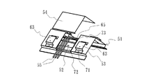
次に、図6から図8に示すように、両棟に傾斜を有する屋根に取り付ける配線引込装置51について説明する。この配線引込装置51は、基台52、カバー台座53、カバー54とからなる。
Next, as shown in FIG. 6 to FIG. 8, a description will be given of the wiring lead-in
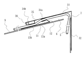
図6(a)に示すように、カバー台座53は、板状材を一部折曲して山型の形状とした山型平板部61からなり、その長手方向中央部分の頂頭部を開口して、配線5が通る通路65を形成している。この山型平板部61は換気棟58の基本的な形態となる基板とほぼ同じ形態とすることが好ましい。
As shown in FIG. 6 (a), the
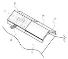
図8に示すように、換気棟58は、屋根9の頭頂部を開口した開口部56から換気をしており、配線引込装置51を換気棟58と連結したときに、カバー台座53の通路65の真下に屋根9の開口部56が位置することになる。なお、カバー台座53の山型平板部61には、台状に形成した全体カバーを取り付けるための取付台63、63が配置されている。
As shown in FIG. 8, the
この通路65から軒方向の両側にかけて基台52を配置することができる基台配置部62、62が形成される。図6に示す実施例では、台座52は基台配置部62、62の一方にのみ取り付け、もう一方には配置していない。両方に配置するか一方に配置するかは、配線55の位置、数量等を考慮して決定すれば良い。
基台52は、図1に示す第一実施例にかかる基台2とほぼ同じ形態であるが、一方のカバー取付台のみを大きくしたものではなく、双方のカバー取付台が同じ大きさである。この基台52には第一の基台配線支持部71、第二の基台配線支持部72が配置され、第一の基台配線支持部71は折り返し片73により一段高い位置に配置される。第一の基台配線支持部71、第二の基台配線支持部72は緩衝材からなり、この緩衝材は弾性を有する発泡性樹脂材からなるものであることは、第一実施例にかかる基台2と同じである。
The
カバー54は、図2(b)に示す第一実施例にかかるカバー3とほぼ同じ形態である。第一のカバー配線支持部81、第二のカバー配線支持部82が配置され、第二のカバー配線支持部82は台83により一段高く配置されている。これも弾性を有する発泡性樹脂材からなる。また、カバー53の先端を折り返して遮断壁84を形成している。
The
図7に示すように、配線55は第二の基台配線支持部72、第一の基台配線支持部71から、通路65を通り、屋根9の開口部56を通って屋内へ入る。
カバー54は、第一実施例と同じく、カバー台座にその周縁を重ねるように取り付ける。そのとき、第一の基台配線支持部71と第一のカバー配線支持部81とが、第二の基台配線支持部72と第二のカバー配線支持部82とが、配線55を支持した状態で互いに接触し、お互いを圧縮する点についても、第一実施例と同様である。
As shown in FIG. 7, the
As with the first embodiment, the
図8に示すように、配線引込装置51に配線55を通して支持した状態で、全体カバー57を取付台63、63に取り付ける。この全体カバー57は換気棟58の外側カバーとほぼ同じ形状であるため、換気棟58と連続して配置することによって、外観上、換気棟58と配線引込装置51とが同じ形態となり、外観上優れた配線引込装置51を提供することができる。また、図示しないが、配線引込装置51に連結部を形成して換気棟58と連結させることもできる。
As shown in FIG. 8, the
1…配線引込装置、2…基台、3…カバー、4…カバー台座、5…配線、6…通路、8…換気棟、12…折り返し片、13a…第一の基台配線支持部、13b…第二の基台配線支持部、21…平板部、24…空洞連結部、34a…第一のカバー配線支持部、34b…第二のカバー配線支持部、36…遮断壁、
51…配線引込装置、52…基台、53…カバー台座、54…カバー、55…配線、56…開口部、58…換気棟、71…第一の基台配線支持部、72…第二の基台配線支持部、81…第一のカバー配線支持部、82…第二のカバー配線支持部
DESCRIPTION OF
DESCRIPTION OF
Claims (5)
少なくとも基台と、カバーとからなり、
前記基台は、配線を下側から支持するものであって、発泡性弾性樹脂材からなる基台配線支持部を有し、
前記カバーは、配線を上側から支持するものであって、発泡性弾性樹脂材からなるカバー配線支持部を有し、
前記基台配線支持部と前記カバー配線支持部は、カバーを基台に取り付けて配線を支持したときに、互いに圧縮し、前記配線を狭持して支持することを特徴とする配線引込装置。 For drawing the wiring of the equipment placed on the roof indoors from the opening,
At least a base and a cover,
The base is for supporting the wiring from below, and has a base wiring support portion made of a foamable elastic resin material,
The cover is for supporting the wiring from above, and has a cover wiring support portion made of a foaming elastic resin material,
The wiring drawing device according to claim 1, wherein the base wiring support portion and the cover wiring support portion compress each other and support the wiring while sandwiching the cover when the cover is attached to the base to support the wiring.
前記基台は、前記開口部の長手方向に沿って配置される換気棟と連続して配置されたことを特徴とする請求項1に記載の配線引込装置。 The opening is an opening for building ventilation that opens a roof top of a sloped roof in the longitudinal direction thereof,
The wiring lead-in device according to claim 1, wherein the base is disposed continuously with a ventilation ridge disposed along a longitudinal direction of the opening.
第一の基台配線支持部は、基台の開口部分側の端辺を延長して上側で折り返した折り返し片の上面に取り付けられたことを特徴とする請求項1または2のいずれかに記載の配線引込装置。 The base wiring support part consists of a first base wiring support part on the opening portion side of the base and a second base wiring support part on the eaves side,
The first base wiring support part is attached to the upper surface of a folded piece that is extended on the upper side by extending an end of the base on the opening portion side. Wiring retractor.
前記第二のカバー配線支持部は、カバーの裏面から台上に配置されたことを特徴とする請求項3に記載の配線引込装置。 The cover wiring support portion includes a first cover wiring support portion corresponding to the first base wiring support portion and a second cover wiring support portion corresponding to the second base wiring support portion. ,
The wiring lead-in device according to claim 3, wherein the second cover wiring support portion is disposed on a table from the back surface of the cover.
換気棟及びその他の屋根部材と連結するための連結手段を有することを特徴とする請求項1、2、3ないし4のいずれかに記載の配線引込装置。
The wiring pull-in device has almost the same form as the ventilation building in appearance,
The wiring drawing-in device according to any one of claims 1, 2, 3 to 4, further comprising connecting means for connecting to a ventilation building and other roof members.
Priority Applications (1)
| Application Number | Priority Date | Filing Date | Title |
|---|---|---|---|
| JP2012240161A JP6129516B2 (en) | 2012-10-31 | 2012-10-31 | Wiring retractor |
Applications Claiming Priority (1)
| Application Number | Priority Date | Filing Date | Title |
|---|---|---|---|
| JP2012240161A JP6129516B2 (en) | 2012-10-31 | 2012-10-31 | Wiring retractor |
Publications (2)
| Publication Number | Publication Date |
|---|---|
| JP2014088731A true JP2014088731A (en) | 2014-05-15 |
| JP6129516B2 JP6129516B2 (en) | 2017-05-17 |
Family
ID=50790830
Family Applications (1)
| Application Number | Title | Priority Date | Filing Date |
|---|---|---|---|
| JP2012240161A Active JP6129516B2 (en) | 2012-10-31 | 2012-10-31 | Wiring retractor |
Country Status (1)
| Country | Link |
|---|---|
| JP (1) | JP6129516B2 (en) |
Cited By (4)
| Publication number | Priority date | Publication date | Assignee | Title |
|---|---|---|---|---|
| JP2015218453A (en) * | 2014-05-15 | 2015-12-07 | Jfe鋼板株式会社 | Wiring storage box for solar panel |
| JP2017044039A (en) * | 2015-08-28 | 2017-03-02 | 積水化学工業株式会社 | Roof wiring structure and building |
| JP2018053707A (en) * | 2016-09-21 | 2018-04-05 | 株式会社トーコー | Construction method of cable lead-in unit such as solar cell and cable lead-in unit such as solar cell |
| JP2020111883A (en) * | 2019-01-08 | 2020-07-27 | 株式会社トーコー | Cable entry unit for solar cells |
Citations (6)
| Publication number | Priority date | Publication date | Assignee | Title |
|---|---|---|---|---|
| JPH1181542A (en) * | 1997-09-04 | 1999-03-26 | Sekisui Chem Co Ltd | Building wrapping joints and cable wiring structure of photovoltaic power generation system |
| JP2603739Y2 (en) * | 1993-12-25 | 2000-03-21 | 大東電材株式会社 | Fixing device for protective pipes for overhead distribution lines |
| JP2000226917A (en) * | 1998-12-04 | 2000-08-15 | Canon Inc | Structure of solar cell roof, construction method, solar power generation device and building |
| JP2000282650A (en) * | 1999-03-31 | 2000-10-10 | Kubota Corp | Roof structure with solar cells and roof structures used for the roof ridge |
| JP2001311279A (en) * | 2000-04-28 | 2001-11-09 | Sekisui House Ltd | Wiring of roof equipment |
| JP2005102398A (en) * | 2003-09-24 | 2005-04-14 | Kubota Matsushitadenko Exterior Works Ltd | Ridge structure |
-
2012
- 2012-10-31 JP JP2012240161A patent/JP6129516B2/en active Active
Patent Citations (7)
| Publication number | Priority date | Publication date | Assignee | Title |
|---|---|---|---|---|
| JP2603739Y2 (en) * | 1993-12-25 | 2000-03-21 | 大東電材株式会社 | Fixing device for protective pipes for overhead distribution lines |
| JPH1181542A (en) * | 1997-09-04 | 1999-03-26 | Sekisui Chem Co Ltd | Building wrapping joints and cable wiring structure of photovoltaic power generation system |
| JP2000226917A (en) * | 1998-12-04 | 2000-08-15 | Canon Inc | Structure of solar cell roof, construction method, solar power generation device and building |
| US20020134421A1 (en) * | 1998-12-04 | 2002-09-26 | Yoshitaka Nagao | Solar cell roof structure, construction method thereof, photovoltaic power generating apparatus, and building |
| JP2000282650A (en) * | 1999-03-31 | 2000-10-10 | Kubota Corp | Roof structure with solar cells and roof structures used for the roof ridge |
| JP2001311279A (en) * | 2000-04-28 | 2001-11-09 | Sekisui House Ltd | Wiring of roof equipment |
| JP2005102398A (en) * | 2003-09-24 | 2005-04-14 | Kubota Matsushitadenko Exterior Works Ltd | Ridge structure |
Cited By (6)
| Publication number | Priority date | Publication date | Assignee | Title |
|---|---|---|---|---|
| JP2015218453A (en) * | 2014-05-15 | 2015-12-07 | Jfe鋼板株式会社 | Wiring storage box for solar panel |
| JP2017044039A (en) * | 2015-08-28 | 2017-03-02 | 積水化学工業株式会社 | Roof wiring structure and building |
| JP2018053707A (en) * | 2016-09-21 | 2018-04-05 | 株式会社トーコー | Construction method of cable lead-in unit such as solar cell and cable lead-in unit such as solar cell |
| JP7005002B2 (en) | 2016-09-21 | 2022-01-21 | 株式会社トーコー | Construction method of cable lead-in unit such as solar cell and cable lead-in unit such as solar cell |
| JP2020111883A (en) * | 2019-01-08 | 2020-07-27 | 株式会社トーコー | Cable entry unit for solar cells |
| JP7194989B2 (en) | 2019-01-08 | 2022-12-23 | 株式会社トーコー | Cable lead-in unit for solar cells, etc. |
Also Published As
| Publication number | Publication date |
|---|---|
| JP6129516B2 (en) | 2017-05-17 |
Similar Documents
| Publication | Publication Date | Title |
|---|---|---|
| JP7005002B2 (en) | Construction method of cable lead-in unit such as solar cell and cable lead-in unit such as solar cell | |
| JP4365449B2 (en) | Solar cell module construction method | |
| KR20080078798A (en) | Solar module frame | |
| JP6208795B2 (en) | Kasagi ventilation parts | |
| JP6129516B2 (en) | Wiring retractor | |
| CN105464294A (en) | Roof system and continuous welding roof layer structure | |
| JP5662003B2 (en) | Installation structure of solar cell module | |
| JP6033585B2 (en) | Multi-functional top structure with sloped roof | |
| JP6085223B2 (en) | Wiring drawing structure and wiring drawing tool | |
| JP2017179730A (en) | Eaves edge structure and building | |
| JP2010084415A (en) | Method and structure for mounting ventilation ridge | |
| JP2019073899A (en) | Photovoltaic power generation device | |
| JP2010248819A (en) | Single-flow roof ventilation building mounting structure | |
| JP4651572B2 (en) | Gradient type ventilation building | |
| JP6688963B2 (en) | Solar power generator | |
| JP6103625B2 (en) | Roof surface ventilation material with wiring processing function | |
| CN105839862B (en) | Roof system, occlus-roof layer structure and slide fastener | |
| CN222836945U (en) | Rear plate of smoke machine and smoke machine | |
| JP2011144574A (en) | Structure of photovoltaic panel-installed roof, and method for constructing the same | |
| JP7240189B2 (en) | Eaves structure | |
| JP4928225B2 (en) | Waterproof structure on the roof | |
| JP2024032934A (en) | Gutter receiving material and eave structure using it | |
| JP3198955U (en) | Solar module equipment | |
| JP6688067B2 (en) | Keraba cosmetics | |
| GB2634535A (en) | A roof tile |
Legal Events
| Date | Code | Title | Description |
|---|---|---|---|
| A621 | Written request for application examination |
Free format text: JAPANESE INTERMEDIATE CODE: A621 Effective date: 20151020 |
|
| A977 | Report on retrieval |
Free format text: JAPANESE INTERMEDIATE CODE: A971007 Effective date: 20160808 |
|
| A131 | Notification of reasons for refusal |
Free format text: JAPANESE INTERMEDIATE CODE: A131 Effective date: 20160817 |
|
| A521 | Request for written amendment filed |
Free format text: JAPANESE INTERMEDIATE CODE: A523 Effective date: 20161011 |
|
| TRDD | Decision of grant or rejection written | ||
| A01 | Written decision to grant a patent or to grant a registration (utility model) |
Free format text: JAPANESE INTERMEDIATE CODE: A01 Effective date: 20170220 |
|
| A61 | First payment of annual fees (during grant procedure) |
Free format text: JAPANESE INTERMEDIATE CODE: A61 Effective date: 20170412 |
|
| R150 | Certificate of patent or registration of utility model |
Ref document number: 6129516 Country of ref document: JP Free format text: JAPANESE INTERMEDIATE CODE: R150 |
|
| R250 | Receipt of annual fees |
Free format text: JAPANESE INTERMEDIATE CODE: R250 |
|
| R250 | Receipt of annual fees |
Free format text: JAPANESE INTERMEDIATE CODE: R250 |
|
| R250 | Receipt of annual fees |
Free format text: JAPANESE INTERMEDIATE CODE: R250 |
|
| R250 | Receipt of annual fees |
Free format text: JAPANESE INTERMEDIATE CODE: R250 |
|
| R250 | Receipt of annual fees |
Free format text: JAPANESE INTERMEDIATE CODE: R250 |
|
| R250 | Receipt of annual fees |
Free format text: JAPANESE INTERMEDIATE CODE: R250 |
|
| R250 | Receipt of annual fees |
Free format text: JAPANESE INTERMEDIATE CODE: R250 |