JP2014088712A - Water jet type removing device for road surface - Google Patents
Water jet type removing device for road surface Download PDFInfo
- Publication number
- JP2014088712A JP2014088712A JP2012239610A JP2012239610A JP2014088712A JP 2014088712 A JP2014088712 A JP 2014088712A JP 2012239610 A JP2012239610 A JP 2012239610A JP 2012239610 A JP2012239610 A JP 2012239610A JP 2014088712 A JP2014088712 A JP 2014088712A
- Authority
- JP
- Japan
- Prior art keywords
- road surface
- ejector
- removing device
- fountain
- pulley
- Prior art date
- Legal status (The legal status is an assumption and is not a legal conclusion. Google has not performed a legal analysis and makes no representation as to the accuracy of the status listed.)
- Pending
Links
- XLYOFNOQVPJJNP-UHFFFAOYSA-N water Substances O XLYOFNOQVPJJNP-UHFFFAOYSA-N 0.000 title claims abstract description 77
- 238000002347 injection Methods 0.000 claims description 34
- 239000007924 injection Substances 0.000 claims description 34
- 239000007921 spray Substances 0.000 claims description 28
- 238000006073 displacement reaction Methods 0.000 claims description 8
- 238000005096 rolling process Methods 0.000 description 17
- 239000000463 material Substances 0.000 description 13
- 230000007246 mechanism Effects 0.000 description 7
- 238000000034 method Methods 0.000 description 7
- 230000008569 process Effects 0.000 description 7
- 229910052782 aluminium Inorganic materials 0.000 description 6
- XAGFODPZIPBFFR-UHFFFAOYSA-N aluminium Chemical compound [Al] XAGFODPZIPBFFR-UHFFFAOYSA-N 0.000 description 6
- 229910001220 stainless steel Inorganic materials 0.000 description 5
- 239000010935 stainless steel Substances 0.000 description 5
- 230000008859 change Effects 0.000 description 3
- 230000002093 peripheral effect Effects 0.000 description 3
- 230000036544 posture Effects 0.000 description 3
- 239000002699 waste material Substances 0.000 description 3
- 230000009471 action Effects 0.000 description 2
- 238000010586 diagram Methods 0.000 description 2
- 239000011435 rock Substances 0.000 description 2
- 229910000831 Steel Inorganic materials 0.000 description 1
- 230000008878 coupling Effects 0.000 description 1
- 238000010168 coupling process Methods 0.000 description 1
- 238000005859 coupling reaction Methods 0.000 description 1
- 238000007599 discharging Methods 0.000 description 1
- 230000000694 effects Effects 0.000 description 1
- 239000004973 liquid crystal related substance Substances 0.000 description 1
- 229910052751 metal Inorganic materials 0.000 description 1
- 239000002184 metal Substances 0.000 description 1
- 230000004048 modification Effects 0.000 description 1
- 238000012986 modification Methods 0.000 description 1
- 239000003973 paint Substances 0.000 description 1
- 239000002245 particle Substances 0.000 description 1
- 230000004044 response Effects 0.000 description 1
- 239000010959 steel Substances 0.000 description 1
Images
Landscapes
- Road Repair (AREA)
- Cleaning By Liquid Or Steam (AREA)
- Special Spraying Apparatus (AREA)
- Nozzles (AREA)
- Coating Apparatus (AREA)
Abstract
Description
本発明は、路面上に付着した付着物や路面表面自体などの被除去物を路面に向けて噴出した高圧の水によって除去する路面用噴水型除去装置に関する。 The present invention relates to a road surface fountain type removing device that removes an object to be removed such as a deposit adhered on a road surface or a road surface itself with high-pressure water ejected toward the road surface.
従来から、路面に向けて高圧の水を噴射することにより路面上に付着している付着物や路面の表面自体などを被除去物として路面から除去する路面用噴水型除去装置が知られている。例えば、下記特許文献1には、円盤状に形成されて回転駆動するノズルホルダの外周部に高圧水を噴射するノズルを少なくとも2つ備えて路面上の白線などを除去する噴流噴射装置が開示されている。 Conventionally, there is known a fountain type removal device for a road surface that removes deposits adhering to the road surface, the surface of the road surface itself, etc. from the road surface as an object to be removed by jetting high pressure water toward the road surface. . For example, Patent Document 1 below discloses a jet injection device that includes at least two nozzles that inject high-pressure water on the outer periphery of a nozzle holder that is formed in a disk shape and is driven to rotate, and removes white lines on a road surface. ing.
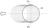
しかしながら、上記特許文献1に記載された噴流噴射装置においては、図8に示すように、噴流噴射装置から噴射される水の円状の噴水軌道90が噴流噴射装置を支持する車両の進行方向(図示矢印参照)に沿って直線的に移動するため、噴水軌道90における幅方向両端部91a,91bが通過した路面上と噴水軌道90におけるその他の部分が通過した路面上とにおける被除去物の除去量に差が生じるという問題があった。すなわち、円状の噴水軌道90においては、幅方向両端部91a,91bにおける軌道部分が噴水軌跡90全体の移動方向に対して平行に近いため、噴水軌道90における幅方向両端部91a,91bが路面上を移動する時間が噴水軌道90におけるその他の部分が移動する時間よりも実質的に長くなる。このため、従来の噴流噴射装置においては、噴水軌道90における幅方向両端部91a,91bが通過した路面上における被除去物の除去量が噴水軌道90におけるその他の部分が通過した路面上における被除去物の除去量よりも多くなる傾向があり、その結果、被除去物の除去作業を行った路面に被除去物の除去量のムラが生じることがあった。なお、図8においては、噴水軌道90が移動する過程を二点鎖線で示している。
However, in the jet injection device described in Patent Document 1, as shown in FIG. 8, the
本発明は上記問題に対処するためなされたもので、被除去物の除去作業を行う路面における除去量のムラを抑えて被除去物を精度良く均一に除去することができる路面用噴水型除去装置を提供することにある。 The present invention has been made to address the above-described problem, and is a fountain type removal device for a road surface that can remove the removal object accurately and uniformly while suppressing unevenness in the removal amount on the road surface where the removal object is removed. Is to provide.
上記目的を達成するため、本発明の特徴は、路面上の被除去物に水を噴射して除去する路面用噴水型除去装置であって、路面に向けて水を噴射する噴射体と、噴射体から噴射される水の噴射方向を円状に変位させるための噴射方向変位手段と、噴射体を路面に沿って移動させる噴射体移動手段と、噴射体が路面に向けて水を噴射している際に噴射体移動手段による噴射体の移動方向に対して交わる方向に噴射体を揺動させる噴射体揺動手段とを備えることにある。 In order to achieve the above object, a feature of the present invention is a road surface fountain type removing device that injects and removes water on an object to be removed on a road surface, and an injection body that injects water toward a road surface, Injection direction displacement means for displacing the injection direction of water injected from the body in a circular shape, injection body moving means for moving the injection body along the road surface, and the injection body injecting water toward the road surface And an ejector oscillating means for oscillating the ejector in a direction intersecting with the direction of movement of the ejector by the ejector moving means.
このように構成した本発明の特徴によれば、路面用噴水型除去装置は、噴射体から噴射させる水を円状に変位させる際、噴射体を噴射体の移動方向に対して交わる方向に揺動させる噴射体揺動手段を備えて構成されている。このため、路面用噴水型除去装置は、噴射される水の円状の軌道である噴水軌道が噴水軌道全体の移動方向に交わる方向(例えば、直交方向)に変位しながら移動するようになる。これにより、路面用噴水型除去装置は、円状の噴水軌道における噴水軌道の移動方向と交わる方向の軌道部分、より具体的には、噴水軌道の移動方向に対して平行に近い軌道部分が路面における特定の位置にその他の駆動部分に比べて相対的に長い時間位置することが防止されるため、被除去物の除去量のムラが生じることを抑えて被除去物を精度よく均一に除去することができる。 According to the feature of the present invention configured as described above, the road surface fountain type removing device swings the spray body in a direction intersecting the moving direction of the spray body when the water sprayed from the spray body is displaced in a circular shape. An ejector swinging means for moving is provided. For this reason, the fountain type removing device for road surface moves while fountain orbits, which are circular orbits of water to be ejected, are displaced in a direction (for example, orthogonal direction) intersecting the movement direction of the entire fountain orbit. As a result, the road surface fountain type removing device is configured so that the track portion in the direction intersecting the moving direction of the fountain track in the circular fountain track, more specifically, the track portion close to parallel to the moving direction of the fountain track is the road surface. Therefore, it is possible to prevent the object to be removed from being removed at a specific position with high precision and evenness by suppressing occurrence of unevenness in the removal amount of the object to be removed. be able to.
なお、上記引用文献1に記載された噴流噴射装置においては、ノズルホルダを備えた装置架台が車両の進行方向に直交する方向、すなわち車幅方向に水平シフトするように構成されている。しかし、上記引用文献1に記載された噴流噴射装置においては、架台は車両側に搭載されたシフト用駆動モータによって車幅方向にスライドされる一方で、架台自身には路面を転動する車輪が設けられているため、水を噴射する除去作業中に架台を車幅方向にスライドできるものではなく、本発明における路面用噴水型除去装置とは構成が異なるとともに本発明における路面用噴水型除去装置による作用効果を発揮するものではない。 In addition, in the jet injection apparatus described in the above cited reference 1, the apparatus mount including the nozzle holder is configured to horizontally shift in a direction orthogonal to the traveling direction of the vehicle, that is, in the vehicle width direction. However, in the jet injection device described in the above cited reference 1, the gantry is slid in the vehicle width direction by the shift drive motor mounted on the vehicle side, while the gantry itself has wheels that roll on the road surface. Since it is provided, the gantry cannot be slid in the vehicle width direction during the removing operation for jetting water, and the configuration is different from the fountain type removing device for road surface according to the present invention and the fountain type removing device for road surface according to the present invention It does not demonstrate the effect of.
また、本発明の他の特徴は、前記路面用噴水型除去装置において、噴射体移動手段は、噴射体および噴射体揺動手段を搭載して路面上を移動する移動体で構成されていることにある。 Another feature of the present invention is that in the fountain mold removing device for a road surface, the ejector moving means is configured by a moving body that mounts the injector and the ejector swinging means and moves on the road surface. It is in.
このように構成した本発明の他の特徴によれば、路面用噴水型除去装置は、噴射体および噴射体揺動手段を搭載して路面上を移動する移動体で構成されているため、路面上を自由に移動しつつこの移動方向に対して交わる方向に噴射体を揺動させることができる。 According to another feature of the present invention configured as described above, the road surface fountain type removing device includes a jet body and a jet body swinging means and is configured by a moving body that moves on the road surface. The ejector can be swung in a direction intersecting with the moving direction while freely moving above.
また、本発明の他の特徴は、前記路面用噴水型除去装置において、噴射方向変位手段は、噴射体を保持する噴射体保持手段と、噴射体保持手段を回転駆動する保持体回転駆動手段とを有し、噴射体揺動手段は、噴射体保持手段を揺動させることにある。 According to another aspect of the present invention, in the road surface fountain type removing device, the ejection direction displacement unit includes: an ejector holding unit that holds the ejector; and a holding body rotation driving unit that rotationally drives the ejector holding unit. And the ejector swinging means swings the ejector holding means.
このように構成した本発明の他の特徴によれば、路面用噴水型除去装置は、噴射体を保持する噴射体保持手段を備えるとともに、保持体回転駆動手段が噴射体保持手段を回転駆動するため、噴射体自体が噴水を円状に変位させる機構を備える必要がなく構成を簡単にできる。また、路面用噴水型除去装置は、噴射体保持手段に異なるタイプの噴射体を付け替えることによって幅広いタイプの噴射体を用いることができるとともに、噴射体が故障した場合であっても迅速に噴射体を交換することができる。 According to another feature of the present invention configured as described above, the road surface fountain type removing device includes the ejector holding means for holding the ejector, and the holding body rotation driving means rotationally drives the ejector holding means. Therefore, it is not necessary for the ejector itself to include a mechanism for displacing the fountain in a circular shape, and the configuration can be simplified. Further, the road surface fountain type removing device can use a wide variety of injectors by changing different types of injectors to the injector holder, and can quickly eject the injector even if the injector fails. Can be exchanged.
また、本発明の他の特徴は、前記路面用噴水型除去装置において、噴射体保持手段は、保持体回転駆動手段によって回転駆動される回転用プーリと、噴射体を保持して回転用プーリに対して着脱自在に装着される噴射体保持体とを備えることにある。 Another feature of the present invention is that in the road surface fountain mold removing device, the ejector holding means includes: a rotating pulley that is rotated by a holding body rotation driving means; and a rotating pulley that holds the injector and rotates. And providing an ejector holding body that is detachably attached thereto.
このように構成した本発明の他の特徴によれば、路面用噴水型除去装置は、回転駆動される回転用プーリに対して噴射体を保持する噴射体保持体を着脱自在に装着されるように構成されている。これにより、路面用噴水型除去装置は、噴射体自体が噴水を円状に変位させる機構を備える必要がなく構成を簡単にできるとともに噴射体保持体に異なるタイプの噴射体を付け替えることによって幅広いタイプの噴射体を用いることができる。また、路面用噴水型除去装置は、噴射体を互いに異なる姿勢で保持する複数種類の噴射体保持体を用意することにより、噴射する水の範囲や角度を簡単に変更することができる。 According to another feature of the present invention configured as described above, the road surface fountain type removing device is configured such that an ejector holding body for holding an ejector is detachably attached to a rotation pulley that is rotationally driven. It is configured. As a result, the road surface fountain type removing device does not need to be provided with a mechanism for causing the fountain to displace the fountain in a circular shape, and the configuration can be simplified. Can be used. Moreover, the road surface fountain mold removing device can easily change the range and angle of water to be sprayed by preparing a plurality of types of spray body holding bodies that hold the spray bodies in different postures.
また、本発明の他の特徴は、前記路面用噴水型除去装置において、噴射体揺動手段は、保持体回転駆動手段における噴射体保持手段の回転中心とは異なる回転中心によって噴射体保持手段を回転させることにある。 Another feature of the present invention is that in the fountain type removing device for a road surface, the ejector swinging means is configured such that the ejector holding means has a rotation center different from the rotation center of the injector holding means in the holding body rotation driving means. Rotate.
このように構成した本発明の他の特徴によれば、路面用噴水型除去装置は、保持体回転駆動手段における噴射体保持手段の回転中心とは異なる位置を回転中心として噴射体保持手段を回転させるため、簡単な構成によって噴射体を揺動させることができる。 According to another feature of the present invention configured as described above, the road surface fountain type removing device rotates the ejector holding means around a position different from the rotation center of the ejector holding means in the holding body rotation driving means. Therefore, the ejector can be swung with a simple configuration.
また、本発明の他の特徴は、前記路面用噴水型除去装置において、噴射体揺動手段は、噴射体保持手段を噴射体の移動方向に対して交わる方向に往復動させることにある。 Another feature of the present invention is that, in the fountain type removing device for a road surface, the spray body swinging means reciprocates the spray body holding means in a direction intersecting the moving direction of the spray body.
このように構成した本発明の他の特徴によれば、路面用噴水型除去装置は、噴射体保持手段を前記噴射体の移動方向に対して交わる方向に往復動させるため、簡単な構成によって噴射体を揺動させることができる。 According to another feature of the present invention configured as described above, the road surface fountain mold removing device reciprocates the ejector holding means in a direction intersecting the moving direction of the ejector. The body can be swung.
また、本発明の他の特徴は、前記路面用噴水型除去装置において、噴射体移動手段は、路面上を転がる3つの車輪を有していることにある。 Another feature of the present invention is that, in the road surface fountain mold removing device, the spray body moving means has three wheels that roll on the road surface.
このように構成した本発明の他の特徴によれば、路面用噴水型除去装置は、噴射体は3つの車輪を有した噴射体移動手段によって路面上を移動する。これにより、路面用噴水型除去装置は、噴射体を路面に対して所謂三点支持するため、路面に凹凸があった場合においても常に安定的に噴射体を移動させることができる。 According to another feature of the present invention configured as described above, in the road surface fountain type removing device, the spray body moves on the road surface by the spray body moving means having three wheels. Thereby, since the fountain type removing device for road surface supports the ejector on the road surface at so-called three points, the ejector can always be stably moved even when the road surface is uneven.
(第1実施形態)
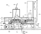
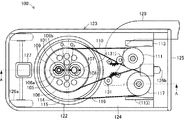
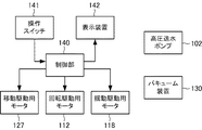
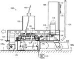
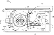
以下、本発明に係る路面用噴水型除去装置の第1実施形態について図面を参照しながら説明する。図1は、本発明に係る路面用噴水型除去装置100の外観構成の概略を示す一部破断側面図である。また、図2は、図1に示す路面用噴水型除去装置100の外観構成における主要部分を概略的に示す一部破断平面図である。また、図3は、図1に示す路面用噴水型除去装置100の作動を制御する制御システムのブロック図である。なお、本明細書において参照する各図は、本発明の理解を容易にするために一部の構成要素を誇張して表わすなど模式的に表している。このため、各図面間および各構成要素間の寸法や比率などは異なっていることがある。この路面用噴水型除去装置100は、道路などの路面Gに形成された白線Lに高圧水を噴射することによって路面G上から白線Lを剥離させて除去するための機械装置である。
(First embodiment)
DESCRIPTION OF EMBODIMENTS Hereinafter, a first embodiment of a road surface fountain mold removing device according to the present invention will be described with reference to the drawings. FIG. 1 is a partially broken side view showing an outline of an external configuration of a road surface fountain
(路面用噴水型除去装置100の構成)
路面用噴水型除去装置100は、噴射体101を備えている。噴射体101は、路面Gに対して高圧水を噴射するための器具であり、ステンレス材を長尺の管状に形成して構成されている。この噴射体101は、一方(図示上側)の端部に高圧水を供給する高圧送水ポンプ102に可撓性を有する送水ホース103を介して接続されているとともに、他方(図示下側)の端部に高圧水を噴射する噴水ノズル104が設けられている。この場合、噴水ノズル104は、高圧送水ポンプ102から供給された高圧水を1本または複数本の水柱状に噴射するノズルを用いることができる。
(Configuration of road surface fountain mold removing device 100)
The road surface fountain
高圧送水ポンプ102は、水を加圧して噴射体101に供給する機械装置であり、図示しない台車上に設けられている。この高圧送水ポンプ102は、図示しない水源(例えば、一般上水道、貯水タンク、貯水池など)から水の供給を受けるとともに、この水を100MPa以上かつ300MPa以下の範囲で加圧した所謂超高圧水を噴射体101に供給する。本実施形態においては、高圧送水ポンプ102は、200MPaの超高圧水を噴射体101に供給する。
The high-
噴射体101は、噴射体保持体105を介して回転用プーリ106に保持されている。噴射体保持体105は、噴射体101を着脱自在に保持するためのアルミニウム製の部材であり、噴射体101が貫通する貫通孔を備えた段付きの円筒状に構成されている。この噴射体保持体105は、噴射体101を保持する貫通孔が垂直方向に対して10°の角度で図示下方に向かって外側に傾斜して形成されるとともに、この貫通孔の内部に噴射体101を回転自在な状態で保持するためのベアリングを備えて構成されている。
The
回転用プーリ106は、噴射体保持体105を介して保持した噴射体101を回転変位させるための機械要素であり、アルミニウム材によって構成されている。この回転用プーリ106には、平面視において中央部に互いに対向した状態で2つの嵌合孔106aが形成されるとともに、これら2つの嵌合孔106aの両側にそれぞれ4つずつのエア導入孔106bがそれぞれ形成されている。これらのうち、2つの嵌合孔106aは、噴射体保持体105および後述するウエイト保持体107がそれぞれ着脱自在に嵌合する段付きの貫通孔である。また、8つのエア導入孔106bは、詳しくは後述する内スカート120の内側領域に外気を導入するための貫通孔である。
The
ウエイト保持体107は、ウエイト108を着脱自在に保持するためのアルミニウム製の部材であり、噴射体保持体105と同様に、ウエイト108が貫通する貫通孔を備えた段付きの円筒状に構成されている。この場合、ウエイト保持体107は、噴射体保持体105と同様に、ウエイト108を保持する貫通孔が垂直方向に対して10°の角度で図示下方に向かって外側に傾斜して形成されている。ウエイト108は、噴射体101を保持して回転駆動する回転用プーリ106において噴射体101とのバランスを合わせるためのステンレス製の錘であり、噴射体101と同等の長さおよび重さの丸棒状に形成されている。なお、路面用噴射型除去装置100は、ウエイト108を省略して構成することもできる。
The
回転用プーリ106は、ベアリング109を介して揺動用プーリ114に回転自在に支持された状態で平ベルト110を介して回転駆動用プーリ111に連結されている。平ベルト110は、回転駆動用プーリ112の回転駆動力を回転用プーリ106に伝達するための機械要素であり、帯状のゴム材をリング状に形成して構成されている。この平ベルト110は、回転用プーリ106および回転駆動用プーリ111に対して摩擦接触した状態で架設されている。回転駆動用プーリ111は、回転駆動用モータ112の回転駆動によって回転する機械要素である。回転駆動用モータ112は、後述する制御部140の作動制御によって回転駆動する電動機であり、支持台113上に固定されている。すなわち、回転用プーリ106は、回転駆動用モータ112の回転駆動によって回転駆動する。本実施形態においては、回転駆動用モータ112は、回転用プーリ106を300rpm以上かつ500rpmの範囲の速度で回転させる。支持台113は、後述する載置板124上に凸状に固定されたステンレス製の棚である。
The
揺動用プーリ114は、回転用プーリ106を回転用プーリ106の回転中心O1とは異なる位置を回転中心O2として回転変位、すなわち、自転する回転プーリ106を自転中心O1とは異なる位置を回転中心O2とする円軌道に沿って公転させるための機械要素であり、アルミニウム材によって構成されている。この揺動用プーリ114の内側には、回転用プーリ106の回転駆動によって回転変位する噴射体101およびウエイト108が貫通可能な貫通孔が形成されている。そして、この揺動用プーリ114は、ベアリング115を介してプーリホルダ122に回転自在に支持された状態で平ベルト116を介して揺動駆動用プーリ117に連結されている。
Swinging
平ベルト116は、前記平ベルト110と同様に、揺動駆動用プーリ117の回転駆動力を揺動用プーリ114に伝達するための機械要素であり、帯状のゴム材をリング状に形成して構成されている。この平ベルト116は、揺動用プーリ114および揺動駆動用プーリ117に対して摩擦接触した状態で架設されている。揺動駆動用プーリ117は、揺動駆動用モータ118の回転駆動によって回転する機械要素である。揺動駆動用モータ118は、制御部140の作動制御によって回転駆動する電動機であり、前記支持台113上に固定されている。すなわち、揺動用プーリ114は、揺動駆動用モータ118の回転駆動によって回転駆動する。本実施形態においては、揺動駆動用モータ118は、揺動用プーリ114を20rpm以上かつ60rpmの範囲の速度で回転させる。
As with the
また、揺動用プーリ114の下面には、リング状のカラー119を介して内スカート120が設けられている。内スカート120は、自転および揺動する噴射体101の周囲を囲むカバーであり、ステンレス材を円筒状に形成して構成されている。この内スカート120は、揺動用プーリ114に固定される固定側内スカート120aと、この固定側内スカート120aの外側に2つの固定ボルト121によって固定側内スカート120aの軸線方向に変位可能に取り付けられた可動側内スカート120bとによって構成されている。すなわち、内スカート120は、2つの固定ボルト121を弛めることによって筒部が伸縮して長さが調整可能に形成されている。この場合、内スカート120は、後述する外スカート128の長さ以下の長さで調整できるように構成されている。
An
プーリホルダ122は、揺動用プーリ114を回転自在に保持する部材であり、アルミニウム材をリング状に形成して構成されている。この場合、プーリホルダ122の内側に形成された貫通孔は、回転用プーリ106の回転駆動によって回転変位する噴射体101およびウエイト108が貫通可能な大きさに形成されている。そして、このプーリホルダ122は、移動台123の載置板124上に固定されている。
The
移動台123は、路面用噴水型除去装置100を構成する部品や機器を支持して路面上を移動させるための台車であり、主として載置板124、把持棒125、前輪126aおよび後輪126bによって構成されている。載置板124は、前記プーリホルダ122を含む路面用噴水型除去装置100を構成する部品や機器を支持する方形平板状のステンレス製の台である。この場合、載置板124には、プーリホルダ122を支持する部分の内側に回転用プーリ106の回転駆動によって回転変位する噴射体101およびウエイト108が貫通可能な貫通孔が形成されている。
The moving table 123 is a cart for supporting the parts and equipment constituting the road surface fountain
把持棒125は、路面用噴水型除去装置100の掴み手となる部分であり、ステンレス製のパイプ材によって構成されている。この把持棒125は、長方形状に形成された載置板124における3辺を囲むとともに路面用噴水型除去装置100の後方に延びる部分が図示上方に屈曲した後水平方向に延びて作業者による把持部分を構成している。
The
前輪126aおよび後輪126bは、路面用噴水型除去装置100を移動させるための輪であり、載置板124の裏面における路面用噴水型除去装置100の前方側および後方側にそれぞれ取り付けられている。これらのうち、路面用噴水型除去装置100の前方側に設けられた2つの前輪126aは、移動駆動用モータ127に連結されて同移動駆動用モータ127によって回転駆動するように構成されている。移動駆動用モータ127は、制御部120の作動制御によって回転駆動する電動機であり、載置板124の表面上に固定されている。一方、路面用噴水型除去装置100の後方側に設けられた1つの後輪126bは、載置板124に対して向きおよび回転が自在なフリーな状態で設けられている。すなわち、移動台123は、2つの前輪126aおよび1つの後輪126bからなる3つの車輪によって路面Gに対して3点支持されている。
The
プーリホルダ122の下面には、外スカート128が設けられている。外スカート128は、前記内スカート120の外側を囲むカバーであり、ステンレス材を円筒状に形成して構成されている。この外スカート128は、内スカート120との間に内スカート120の容積よりも小さい容積のリング状のバキューム領域(空間)VEを形成する内径でかつ路面Gとの間に所定の隙間を介しつつ内スカート120よりも長い長さで形成されている。この外スカート128は、路面Gとの間に所定の隙間を介しつつ内スカート120よりも長い長さで形成されている。この場合、外スカート128と路面Gとの間の隙間は、路面Gから突出する白線の厚さ以上、より具体的には、3mm以上かつ10mm以内が好適である。また、外スカート128の内径は、内スカート120の外周面との間に30mm以上かつ60mm以内の隙間が形成される大きさに形成されているとよい。
An
この外スカート128の壁面には、外スカート128の内側領域に貫通した状態で排出ダクト129が接続されている。排出ダクト129は、噴射体101による加圧水の噴射により剥離された白線屑を空気とともに外スカート128の内側領域、より具体的にはバキューム領域VEから排出するための管であり、ステンレス材を筒状に形成して構成されている。この排出ダクト129は、バキューム装置130に接続されている。バキューム装置130は、空気を吸引するとともに吸引した空気から白線屑を分別して排気する機械装置であり、移動台123とは別の図示しない台車上に設けられている。
A
また、移動台123における載置板124上には、平ベルト110,116の下方にテンショナ131がそれぞれ設けられている。テンショナ131は、平ベルト110,116にそれぞれテンションを付与して弛みを防止するための器具である。また、載置板124上は、外筐132によって覆われている。外筐132は、載置板124上を覆う筐体であり、ステンレス材を板金加工により箱状に形成して構成されている。この外筐132における路面用噴水型除去装置100の後ろ側には、制御ボックス133が設けられている。
Further,
制御ボックス133は、この路面用噴水型除去装置100の作動を制御する制御部140を収容する鋼板製の収容箱であり、移動台123上に設けられた外筐132上に固定的に取り付けられている。制御部140は、CPU、ROM、RAMなどからなるマイクロコンピュータによって構成されており、回転駆動用モータ112、揺動駆動用モータ118および移動駆動用モータ127の各作動をそれぞれ制御する。具体的には、制御部140は、後述する操作スイッチ141の操作に応じてROMなどの記憶装置に予め記憶された制御プログラムを実行することによって回転駆動用モータ112、揺動駆動用モータ118および移動駆動用モータ127の各作動の開始および停止をそれぞれ制御する。
The
また、制御ボックス133の外表面には、路面用噴水型除去装置100の後方に向かって操作スイッチ141および表示装置142がそれぞれ露出した状態で設けられている。操作スイッチ141は、制御部140に対して作業者の指示を入力するための入力装置であり、回転駆動用モータ112、揺動駆動用モータ118および移動駆動用モータ127の各作動の開始および停止をそれぞれ指示するための押しボタンによって構成されている。また、表示装置142は、制御部140の作動状態を表示するための液晶表示画面である。なお、この制御ボックス133内には、外部電源から導入した電力を回転駆動用モータ112、揺動駆動用モータ118および移動駆動用モータ127にそれぞれ供給するための図示しない電源部なども備えているが、これらについては、本発明に直接関わらないため、その説明は省略する。
Further, the
(路面用噴水型除去装置100の作動)
次に、このように構成された路面用噴水型除去装置100の作動について説明する。まず、作業者は、路面用噴水型除去装置100、高圧送水ポンプ102およびバキューム装置130をそれぞれ用意するとともに、これらを互いに接続する。次いで、作業者は、路面用噴水型除去装置100における図示しない電源スイッチをONにすることにより制御部140を起動させる。これにより、制御部140は、ROMなどの記憶装置に予め記憶された制御プログラムを実行することによって作動を介して作業者からの指示を待つ待機状態となる。
(Operation of road surface fountain mold removing device 100)
Next, the operation of the road surface fountain
次に、作業者は、路面G上の白線Lの除去作業を開始する。具体的には、作業者は、移動体123を人手で押すことにより路面用噴水型除去装置100を除去対象となる白線L上に移動させる。次に、作業者は、内スカート120の長さを調節する。この場合、作業者は、内スカート120内および外スカート128内での吸引環境に応じて内スカート120の長さを調節する。
Next, the worker starts removing white lines L on the road surface G. Specifically, the operator moves the road surface fountain
具体的には、作業者は、路面Gに向けて噴射した霧状の水および除去した白線屑の外スカート128外への漏出(例えば、白線屑が粉状の場合)には、内スカート120における可動側内スカート120bを下げる。一方、作業者は、除去した白線屑の粒径が比較的大きい場合には、内スカート120内スカート120における可動側内スカート120bを上昇させることにより、噴射体101から高圧水が噴射される路面Gに排出ダクト129が露出するようにする。なお、内スカート120の長さの調整は、移動体123を傾斜させて行うことができる。
Specifically, when the worker leaks mist-like water jetted toward the road surface G and the removed white line debris to the outside of the outer skirt 128 (for example, when the white line debris is powdery), the
次に、作業者は、操作スイッチ141を操作することにより制御部141に対して回転駆動用モータ112、揺動駆動用モータ118および移動駆動用モータ127の各作動の開始を指示する。これにより、路面用噴水型除去装置100は、噴射体101を回転用プーリ106の回転中心O1を回転中心として回転変位させるとともに、この回転変位する噴射体101を揺動用プーリ114の回転中心O2を回転中心として更に回転変位させながら前輪126aを回転駆動させて前進(図1において左側)(図示矢印参照)を開始する。
Next, the operator operates the
次いで、作業者は、高圧送水ポンプ102およびバキューム装置130における図示しない電源スイッチをONにすることによりこれらをそれぞれ起動させる。これにより、路面用噴水型除去装置100は、噴射体101の噴水ノズル104から高圧の水の噴射が開始されるとともに、内スカート120および外スカート128内における空気の吸引が排出ダクト129を通じて開始される。
Next, the operator activates the high pressure
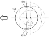
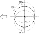
この場合、回転用プーリ106の回転中心O1と揺動用プーリ114の回転中心O2とが互いに異なっている。このため、路面用噴水型除去装置100は、噴射体101の前方への移動に際して回転用プーリ106の回転駆動によって円運動する噴射体101を噴射体101の移動方向に対して交わる方向(本実施形態においては直交する方向)に揺動させることができる。より具体的には、路面用噴水型除去装置100は、図4に示すように、噴射体101における円状の噴水軌道150の幅方向両端部151a,151b、換言すれば、噴水軌道150における噴水軌道150全体の移動方向(図示矢印参照)に対して平行に近い軌道部分が路面用噴水型除去装置100の移動とともに路面用噴水型除去装置100の幅方向に揺動させる。
In this case, the rotation center O 2 of the rotation center O 1 and the
これにより、路面用噴水型除去装置100は、円状の噴水軌道150の幅方向両端部151a,151bが路面用噴水型除去装置100の移動方向と平行に移動することが防止されて噴射体101から噴射された高圧水が路面G上における特定の場所に相対的に長時間当て続けられることが防止できる。したがって、路面用噴水型除去装置100は、噴射体101から噴射させた高圧水によって路面G上の白線Lをムラなく均一に除去することができる。
As a result, the road surface fountain
一方、路面用噴水型除去装置100における内スカート120および外スカート128の各内側領域は、排出ダクト129を介して空気が吸引されるとともに回転用プーリ106に形成されたエア導入孔106bを介して外気が導入される。このため、噴射体101から噴射された水および路面Gから剥がされた白線屑は排出ダクト129を通じて吸引される。この場合、内スカート120内の水および白線屑は、内スカート120の下端部と路面Gとの間に設けられた隙間を介して内スカート120と外スカート128との間のリング状のバキューム領域VEに導かれる。
On the other hand, each of the inner regions of the
この場合、内スカート120の内側領域と外側領域とは内スカート120と路面Gとの間に形成された隙間、換言すれば、流路が狭められたオリフィス部を介して連通している。そして、この隙間は、外カバー128の下端部と路面Gとの間の隙間よりも広く形成されている。これらにより、路面用噴水型除去装置100は、路面Gに噴射されて飛び散った水および路面Gから剥がされた白線屑を内スカート120の下端部と路面Gとの間の隙間を介して効果的に外スカート128の内側におけるリング状のバキューム領域VEに導くとともに、外スカート128の内側におけるバキューム領域VEに導かれた水および白線屑を外スカート128の外側への漏出を抑えながら効果的に吸引して回収することができる。なお、路面G上からの白線Lの除去作業中においては、揺動用プーリ114の回転駆動によって内スカート120も回転駆動している。
In this case, the inner region and the outer region of the
排出ダクト129を介して吸引された空気、水および白線屑からなる吸引物は、図示しないフィルタなどを介して互いに分離されて水と白線屑とがそれぞれ別々に回収される。この場合、路面用噴水型除去装置100は、回収した水を再び白線Lの除去作業に用いる。すなわち、作業者は、路面用噴水型除去装置100を移動させながら連続的に白線Lの除去作業を行うことができる。そして、白線Lの除去作業を終了する場合には、作業者は、高圧送水ポンプ102およびバキューム装置130における図示しない電源スイッチをOFFにしてこれらの作動を停止させた後、操作スイッチ141を操作することによって制御部140に対して回転駆動用モータ112、揺動駆動用モータ118および移動駆動用モータ127の各作動の停止を指示する。これにより、作業者は、路面用噴水型除去装置100における回転駆動用モータ112、揺動駆動用モータ118、移動駆動用モータ127、高圧送水ポンプ102およびバキューム装置130の各作動を停止させて白線Lの除去作業を終了することができる。
The sucked material composed of air, water, and white line waste sucked through the
上記作動説明からも理解できるように、上記第1実施形態によれば、路面用噴水型除去装置100は、噴射体101から噴射させる水を円状に変位させる際、噴射体101を噴射体101の移動方向に対して交わる方向に揺動させるように構成されている。このため、路面用噴水型除去装置100は、噴射される水の円状の軌道である噴水軌道150が噴水軌道150全体の移動方向に交わる方向(例えば、直交方向)に変位しながら移動するようになる。これにより、路面用噴水型除去装置100は、円状の噴水軌道150における噴水軌道150の移動方向と交わる方向の軌道部分である幅方向両端部151a,151b、より具体的には、噴水軌道の移動方向に対して平行に近い軌道部分が路面における特定の位置にその他の駆動部分に比べて相対的に長い時間位置することが防止されるため、白線Lの除去量のムラが生じることを抑えて白線Lを精度よく均一に除去することができる。
As can be understood from the above description of the operation, according to the first embodiment, the road surface fountain
(第2実施形態)
次に、本発明に係る路面用噴水型除去装置の第2実施形態について図面を参照しながら説明する。図5は、本発明に係る路面用噴水型除去装置200の外観構成の概略を示す一部破断側面図である。また、図6は、図5に示す路面用噴水型除去装置200の外観構成における主要部分を概略的に示す一部破断平面図である。この第2実施形態においては、上記第1実施形態における構成要素と同一の部分については同一の符号を付して、その説明は適宜省略する。この第2実施形態に係る路面用噴水型除去装置200は、回転用プーリ106を路面用噴水型除去装置200の幅方向に直線状に往復変位させる点において上記第1実施形態における路面用噴水型除去装置100と異なる。
(Second Embodiment)
Next, a second embodiment of the road surface fountain mold removing device according to the present invention will be described with reference to the drawings. FIG. 5 is a partially broken side view showing an outline of an external configuration of the road surface fountain
(路面用噴水型除去装置200の構成)
具体的には、路面用噴水型除去装置200は、回転用プーリ106がベアリング109を介して揺動用ベース161に回転自在な状態で支持されている。揺動用ベース161は、回転用プーリ106の回転変位を許容した状態で回転用プーリ106を路面用噴水型除去装置200の進行方向に直交する幅方向に往復動可能に支持する部材であり、アルミニウム材を平面視で方形筒状に形成して構成されている。この場合、揺動用ベース161の中央部分に形成された貫通孔は、前記揺動用プーリ114と同様に、回転用プーリ106の回転駆動によって回転変位する噴射体101およびウエイト108が貫通可能な大きさの円形に形成されている。
(Configuration of road surface fountain mold removing device 200)
Specifically, in the road surface fountain
この揺動用ベース161は、外周部分から張り出した状態で4つの転動ベアリング162が設けられており、この転動ベアリング162を介して転動レール163に支持されている。転動ベアリング162は、揺動用ベース161を路面用噴水型除去装置200の幅方向に往復動させるための機械要素であり、転動レール163内に転がり可能な状態で嵌め込まれている。転動レール163は、転動ベアリング162を路面用噴水型除去装置200の幅方向に転がり変位させるための軌道部材であり、ステンレス材を断面コ字状に形成されている。この転動レール163は、移動体123の載置板124上における転動ベース161の周囲であって転動ベアリング162に対応する位置にそれぞれ固定されている。そして、この載置板124の裏面には、内スカート120が取り付けられている。すなわち、本第2実施形態においては、内スカート120は、載置板124に固定されているため、白線Lの除去作業中において不動である。
The rocking
また、揺動用ベース161における外周部には、路面用噴水型除去装置200の後方(図示右側)に向かって張り出した連結片164を介して揺動機構165が連結されている。揺動機構165は、揺動ベース161を路面用噴水型除去装置200の幅方向に揺動させる部材群であり、主として、偏芯片166、揺動棒167および支持柱168によって構成されている。偏芯片166は、揺動駆動用モータ118の回転駆動軸に接続されるとともに、この回転駆動軸の径方向外側に延びるプレート体である。
Further, a
一方、揺動棒167は、揺動用ベース161と揺動駆動用モータ118とを互いに連結するためのアルミニウム製の板状部材であり、移動体123の載置板124上に起立する支持柱168に対して回転自在の状態で支持されている。この揺動棒167の両端部には、それぞれ長孔状の貫通孔が形成されており、これらの各長孔を介して揺動用ベース161の連結片164および揺動駆動用モータ118に接続された偏芯片166がそれぞれ回動自在に連結されている。
On the other hand, the
(路面用噴水型除去装置200の作動)
このように構成した路面用噴水型除去装置200による白線Lの除去作業時においては、噴射体101から高圧水が噴射された状態で回転する回転用プーリ106が揺動される。具体的には、作業者は、噴射体101から高圧水が噴射された状態において操作スイッチ141を操作することにより制御部141を介して揺動駆動用モータ118の作動を開始させる。これにより、路面用噴水型除去装置200は、図6に示すように、揺動棒167が支持柱168を回動中心として路面用噴水型除去装置200の幅方向に延びる円弧軌道上を往復変位することによって揺動ベース161を同幅方向に往復変位させることができる。
(Operation of road surface fountain mold removing device 200)
During the removal operation of the white line L by the road surface fountain
すなわち、路面用噴水型除去装置200は、噴射体101の前方への移動(図示矢印参照)に際して回転用プーリ106の回転駆動によって円運動する噴射体101を噴射体101の移動方向に対して交わる方向(本実施形態においては直交する方向)に揺動させることができる。より具体的には、路面用噴水型除去装置200は、図7に示すように、噴射体101における円状の噴水軌道150の幅方向両端部151a,151b、換言すれば、噴水軌道150における噴水軌道150全体の移動方向(図示矢印参照)に対して平行に近い軌道部分が路面用噴水型除去装置200の移動とともに路面用噴水型除去装置100の幅方向に揺動させる。
In other words, the road surface fountain
これにより、路面用噴水型除去装置200は、円状の噴水軌道150の幅方向両端部151a,151bが路面用噴水型除去装置200の移動方向と平行に移動することが防止されて噴射体101から噴射された高圧水が路面G上における特定の場所に相対的に長時間当て続けられることが防止できる。したがって、路面用噴水型除去装置200は、噴射体101から噴射させた高圧水によって路面G上の白線Lをムラなく均一に除去することができる。
As a result, the road surface fountain
上記作動説明からも理解できるように、上記第2実施形態によれば、路面用噴水型除去装置200は、噴射体101から噴射させる水を円状に変位させる際、噴射体101を噴射体101の移動方向に対して交わる方向に揺動させるように構成されている。このため、路面用噴水型除去装置200は、噴射される水の円状の軌道である噴水軌道150が噴水軌道150全体の移動方向に交わる方向(例えば、直交方向)に変位しながら移動するようになる。これにより、路面用噴水型除去装置200は、円状の噴水軌道150における噴水軌道150の移動方向と交わる方向の軌道部分である幅方向両端部151a,151b、より具体的には、噴水軌道の移動方向に対して平行に近い軌道部分が路面における特定の位置にその他の駆動部分に比べて相対的に長い時間位置することが防止されるため、白線Lの除去量のムラが生じることを抑えて白線Lを精度よく均一に除去することができる。
As can be understood from the above description of the operation, according to the second embodiment, the road surface fountain
さらに、本発明の実施にあたっては、上記各実施形態に限定されるものではなく、本発明の目的を逸脱しない限りにおいて種々の変更が可能である。 Further, the implementation of the present invention is not limited to the above-described embodiments, and various modifications can be made without departing from the object of the present invention.
例えば、上記各実施形態においては、噴射体101から噴射された高圧水は噴射体101が回転用プーリ106によって回転駆動されることにより円状の軌道150上を変位するように構成されている。すなわち、上記各実施形態における回転用プーリ106、回転駆動用プーリ111および回転駆動用モータ112が、本発明に係る噴射方向変位手段に相当する。しかし、この噴射方向変位手段は、噴射体101から噴射される水の噴射方向を円状の軌道150で変位するように構成されていれば、必ずしも上記実施形態に限定されるものではない。例えば、噴射方向変位手段は、噴水ノズル104を噴射体101に回転可能に設けた状態で路面用噴水型除去装置100,200に可動的または固定的に保持させることにより噴水方向を変化させることができる。なお、この場合、噴射体101から噴射される高圧水の軌道150は、円の他に楕円を含むものである。
For example, in each of the above-described embodiments, the high-pressure water ejected from the
また、上記各実施形態においては、噴射体101は噴射体保持体105によって図示下方に向かって外側に傾斜して保持されている。しかし、噴射体101は、路面Gに向かって高圧水を噴射するように保持されていればよく、必ずしも、上記実施形態に限定されるものではない。すなわち、噴射体101は、例えば、上記各実施形態における10°以外の傾斜角度(例えば、5°や20°)で高圧水を噴射する姿勢で保持されていてもよいし、
路面Gに向かって直交する姿勢で保持されていてもよい。また、路面用噴水型除去装置100,200は、噴射体101を傾斜させる角度に応じた噴射体保持体105を予め用意しておくことにより、噴射体101を傾斜角度ごとの噴射体保持体105に付け替えることによって噴水の噴射角度を容易に変更することができる。
Further, in each of the above embodiments, the
It may be held in a posture orthogonal to the road surface G. In addition, the road surface fountain
また、上記各実施形態においては、噴射体101は移動駆動用モータ127が搭載された移動体123によって路面G上を移動するように構成されている。すなわち、上記各実施形態における路面用噴水型除去装置100,200は、自走式で構成されている。この場合、上記各実施形態における移動体123および移動駆動用モータ127が本発明に係る噴射体移動手段に相当する。しかし、噴射体移動手段は、噴射体101を路面Gに沿って移動させることができれば、必ずしも上記各実施形態に限定されるものではない。例えば、噴射体移動手段は、上記各実施形態における移動体123から移動駆動用モータ127を省略して手押し式の台車として構成するができる。また、噴射体移動手段は、移動体123に別体で構成されて移動体123に連結される駆動体、例えば、自動車を含んで構成することもできる。
Further, in each of the above embodiments, the
このように噴射体移動手段を自動車などの自走式車両を含んで構成した場合、噴射体101を揺動させる噴射体揺動手段を自走式車両側に設けることができる。例えば、上記第1実施形態における揺動駆動用プーリ117および揺動駆動用モータ118や上記第2実施形態における偏芯片166、揺動棒167および揺動駆動用モータ118を自走式車両側に設けることができる。
In this way, when the injector moving means includes a self-propelled vehicle such as an automobile, the injector swinging means for swinging the
また、上記各実施形態においては、移動体123は、2つの前輪126aと1つの後輪126bからなる3つの車輪を備えて構成されている。これにより、移動体123は、噴射体101を路面Gに対して所謂三点支持するため、路面Gに凹凸があった場合においても常に安定的に噴射体101を移動させることができる。しかし、移動体123は、路面G上において噴射体101を移動させることができれば、必ずしも上記実施形態に限定されるものではない。すなわち、移動体123は、4つ以上の車輪を備えて構成されていてもよいし、車輪に代えてまたは加えて無限軌道を備えて構成されていてもよい。
Further, in each of the above-described embodiments, the moving
また、上記第1実施形態においては、揺動用プーリ114、平ベルト116、揺動駆動用プーリ117、揺動駆動用モータ118およびプーリホルダ122によって噴射体101を揺動させるように構成した。また、上記第2実施形態においては、揺動用ベース161、転動ベアリング162、転動レール163、連結片164および揺動機構165によって噴射体101を揺動させるように構成した。すなわち、上記第1実施形態においては揺動用プーリ114、平ベルト116、揺動駆動用プーリ117、揺動駆動用モータ118およびプーリホルダ122が本発明に係る噴射体揺動手段に相当し、第2実施形態においては、揺動用ベース161、転動ベアリング162、転動レール163、連結片164および揺動機構165が本発明に係る噴射体揺動手段に相当する。しかし、これらの噴射体揺動手段は、噴射体101を路面Gにおける白線Lに沿った噴射体101の移動方向に対して直交する方向に変位させるように構成すれば、必ずしも上記各実施形態に限定されるものではない。
In the first embodiment, the
また、上記各実施形態においては、路面用噴水型除去装置100,200は、路面G上の白線Lを被除物とした。しかし、路面用噴水型除去装置100,200は、路面G上の白線L以外のもの、例えば、塗料、異物、汚れなどの各種付着物を被除去物として除去することができる。また、路面用噴水型除去装置100,200は、路面Gの表面自体を被除去物として除去することもできる。すなわち、路面用噴水型除去装置100,200は、路面Gに対する付着物除去装置、ハツリ装置および/または目粗し装置としても実施できる。
Moreover, in each said embodiment, the fountain
G…路面、L…白線、O1…回転用プーリの回転中心、O2…揺動用プーリの回転中心、VE…バキューム領域、
90,150…噴水軌道、91a,91b,151a,151b…幅方向両端部、
100,200…路面用噴水型除去装置、101…噴射体、102…高圧送水ポンプ、103…送水ホース、104…噴水ノズル、105…噴射体保持体、106…回転用プーリ、106a…嵌合孔、106b…エア導入孔、107…ウエイト保持体、108…ウエイト、109…ベアリング、110…平ベルト、111…回転駆動用プーリ、112…回転駆動用モータ、113…支持台、
114…揺動用プーリ、115…ベアリング、116…平ベルト、117…揺動駆動用プーリ、118…揺動駆動用モータ、119…カラー、120…内スカート、120a…固定側内スカート、120b…可動側内スカート、121…固定ボルト、122…プーリホルダ、
123…移動体、124…載置板、125…把持棒、126a…前輪、126b…後輪、127…移動駆動用モータ、128…外スカート、
129…排出ダクト、130…バキューム装置、131…テンショナ、132…外筐、133…制御ボックス、
140…制御部、141…操作スイッチ、142…表示装置、
161…揺動用ベース、162…転動ベアリング、163…転動レール、164…連結片、165…揺動機構、166…偏芯片、167…揺動棒、168…支持柱。
G ... road surface, L ... white line, O 1 ... rotation center of rotation pulley, O 2 ... rotation center of swing pulley, VE ... vacuum region,
90, 150 ... fountain orbit, 91a, 91b, 151a, 151b ... both ends in the width direction,
DESCRIPTION OF SYMBOLS 100,200 ... Road surface fountain type removal apparatus, 101 ... Injection body, 102 ... High pressure water supply pump, 103 ... Water supply hose, 104 ... Fountain nozzle, 105 ... Injection body holding body, 106 ... Rotation pulley, 106a ...
114: Swing pulley, 115 ... Bearing, 116 ... Flat belt, 117 ... Swing drive pulley, 118 ... Swing drive motor, 119 ... Collar, 120 ... Inner skirt, 120a ... Fixed side inner skirt, 120b ...
123: moving body, 124: mounting plate, 125 ... gripping rod, 126a ... front wheel, 126b ... rear wheel, 127 ... motor for movement drive, 128 ... outer skirt,
129 ... Discharge duct, 130 ... Vacuum device, 131 ... Tensioner, 132 ... Outer casing, 133 ... Control box,
140 ... control unit, 141 ... operation switch, 142 ... display device,
Reference numeral 161: swing base, 162: rolling bearing, 163: rolling rail, 164: coupling piece, 165: swing mechanism, 166: eccentric piece, 167: swing bar, 168: support column.
Claims (7)
前記路面に向けて水を噴射する噴射体と、
前記噴射体から噴射される水の噴射方向を円状に変位させるための噴射方向変位手段と、
前記噴射体を前記路面に沿って移動させる噴射体移動手段と、
前記噴射体が前記路面に向けて水を噴射している際に前記噴射体移動手段による前記噴射体の移動方向に対して交わる方向に前記噴射体を揺動させる噴射体揺動手段とを備えることを特徴とする路面用噴水型除去装置。 A fountain type removing device for road surface that jets and removes water on an object to be removed on the road surface,
An injection body for injecting water toward the road surface;
An injection direction displacement means for displacing the injection direction of water injected from the injection body in a circular shape;
An ejector moving means for moving the ejector along the road surface;
An ejector oscillating means for oscillating the ejector in a direction intersecting the moving direction of the ejector by the ejector moving means when the ejector is ejecting water toward the road surface; A fountain type removing device for road surfaces characterized by the above.
前記噴射体移動手段は、
前記噴射体および前記噴射体揺動手段を搭載して前記路面上を移動する移動体で構成されていることを特徴とする路面用噴水型除去装置。 The road surface fountain mold removing device according to claim 1,
The ejector moving means includes:
A road surface fountain type removing device comprising a movable body mounted with the spray body and the spray body swinging means and moving on the road surface.
前記噴射方向変位手段は、
前記噴射体を保持する噴射体保持手段と、
前記噴射体保持手段を回転駆動する保持体回転駆動手段とを有し、
前記噴射体揺動手段は、
前記噴射体保持手段を揺動させることを特徴とする路面用噴水型除去装置。 In the fountain type removal apparatus for road surface according to claim 1 or claim 2,
The ejection direction displacement means is
An injection body holding means for holding the injection body;
Holding body rotation driving means for rotationally driving the ejector holding means,
The ejector swinging means includes:
A road surface fountain mold removing device characterized by swinging the spray body holding means.
前記噴射体保持手段は、
前記保持体回転駆動手段によって回転駆動される回転用プーリと、
前記噴射体を保持して前記回転用プーリに対して着脱自在に装着される噴射体保持体とを備えることを特徴とする路面用噴水型除去装置。 In the fountain type removing apparatus for road surface according to claim 3,
The ejector holding means includes:
A rotation pulley that is rotated by the holding body rotation driving means;
A road surface fountain mold removing device comprising: an ejector holding body that holds the ejector and is detachably attached to the rotation pulley.
前記噴射体揺動手段は、
前記保持体回転駆動手段における前記噴射体保持手段の回転中心とは異なる回転中心によって前記噴射体保持手段を回転させることを特徴とする路面用噴水型除去装置。 In the fountain type removing device for a road surface according to claim 3 or claim 4,
The ejector swinging means includes:
The road surface fountain mold removing device, wherein the spray body holding means is rotated by a rotation center different from the rotation center of the spray body holding means in the holding body rotation driving means.
前記噴射体揺動手段は、
前記噴射体保持手段を前記噴射体の移動方向に対して交わる方向に往復動させることを特徴とする路面用噴水型除去装置。 In the fountain type removing device for a road surface according to claim 3 or claim 4,
The ejector swinging means includes:
The road surface fountain type removing device, wherein the spray body holding means is reciprocated in a direction intersecting with a moving direction of the spray body.
前記噴射体移動手段は、
前記路面上を転がる3つの車輪を有していることを特徴とする路面用噴水型除去装置。
In the fountain type removing device for a road surface according to any one of claims 1 to 6,
The ejector moving means includes:
A fountain mold removing device for a road surface, comprising three wheels that roll on the road surface.
Priority Applications (1)
| Application Number | Priority Date | Filing Date | Title |
|---|---|---|---|
| JP2012239610A JP2014088712A (en) | 2012-10-30 | 2012-10-30 | Water jet type removing device for road surface |
Applications Claiming Priority (1)
| Application Number | Priority Date | Filing Date | Title |
|---|---|---|---|
| JP2012239610A JP2014088712A (en) | 2012-10-30 | 2012-10-30 | Water jet type removing device for road surface |
Publications (2)
| Publication Number | Publication Date |
|---|---|
| JP2014088712A true JP2014088712A (en) | 2014-05-15 |
| JP2014088712A5 JP2014088712A5 (en) | 2015-11-05 |
Family
ID=50790811
Family Applications (1)
| Application Number | Title | Priority Date | Filing Date |
|---|---|---|---|
| JP2012239610A Pending JP2014088712A (en) | 2012-10-30 | 2012-10-30 | Water jet type removing device for road surface |
Country Status (1)
| Country | Link |
|---|---|
| JP (1) | JP2014088712A (en) |
Cited By (4)
| Publication number | Priority date | Publication date | Assignee | Title |
|---|---|---|---|---|
| JP2017203304A (en) * | 2016-05-12 | 2017-11-16 | レントリー多摩株式会社 | Scattering / dust suction system |
| CN107774516A (en) * | 2017-11-26 | 2018-03-09 | 金陈敏 | A kind of automatic gluing machine for automobile luggage racks |
| CN110761234A (en) * | 2019-11-18 | 2020-02-07 | 南通威而多专用汽车制造有限公司 | Double-disc rotary high-pressure water jet cleaning trolley |
| JP2020151695A (en) * | 2019-03-24 | 2020-09-24 | ウラカミ合同会社 | Device with rotating nozzle |
Citations (4)
| Publication number | Priority date | Publication date | Assignee | Title |
|---|---|---|---|---|
| JPH0332953U (en) * | 1989-07-28 | 1991-03-29 | ||
| JPH0671565A (en) * | 1991-06-08 | 1994-03-15 | Nippon Kotsu Sangyo Kk | Grinding attachment for marking of road surface |
| JP2005230982A (en) * | 2004-02-20 | 2005-09-02 | Atsuji Tekko Kk | Overhead position polishing/cleaning device |
| JP2007283183A (en) * | 2006-04-14 | 2007-11-01 | Teruo Yahiro | Construction method and construction system by water-foam jet |
-
2012
- 2012-10-30 JP JP2012239610A patent/JP2014088712A/en active Pending
Patent Citations (4)
| Publication number | Priority date | Publication date | Assignee | Title |
|---|---|---|---|---|
| JPH0332953U (en) * | 1989-07-28 | 1991-03-29 | ||
| JPH0671565A (en) * | 1991-06-08 | 1994-03-15 | Nippon Kotsu Sangyo Kk | Grinding attachment for marking of road surface |
| JP2005230982A (en) * | 2004-02-20 | 2005-09-02 | Atsuji Tekko Kk | Overhead position polishing/cleaning device |
| JP2007283183A (en) * | 2006-04-14 | 2007-11-01 | Teruo Yahiro | Construction method and construction system by water-foam jet |
Cited By (6)
| Publication number | Priority date | Publication date | Assignee | Title |
|---|---|---|---|---|
| JP2017203304A (en) * | 2016-05-12 | 2017-11-16 | レントリー多摩株式会社 | Scattering / dust suction system |
| CN107774516A (en) * | 2017-11-26 | 2018-03-09 | 金陈敏 | A kind of automatic gluing machine for automobile luggage racks |
| JP2020151695A (en) * | 2019-03-24 | 2020-09-24 | ウラカミ合同会社 | Device with rotating nozzle |
| WO2020194896A1 (en) * | 2019-03-24 | 2020-10-01 | ウラカミ合同会社 | Device comprising rotary nozzle |
| JP7222163B2 (en) | 2019-03-24 | 2023-02-15 | ウラカミ合同会社 | Apparatus with rotating nozzle |
| CN110761234A (en) * | 2019-11-18 | 2020-02-07 | 南通威而多专用汽车制造有限公司 | Double-disc rotary high-pressure water jet cleaning trolley |
Similar Documents
| Publication | Publication Date | Title |
|---|---|---|
| JP2014088712A (en) | Water jet type removing device for road surface | |
| JP4940331B2 (en) | Hydraulic scaler | |
| JP2015003286A (en) | Water jet type removal device and water jet type removal method | |
| JP2014088713A (en) | Water jet type removing device for road surface | |
| JP3201879U (en) | Road surface fountain removal device | |
| US20200147756A1 (en) | Mobile blasting apparatus | |
| JP3192958U (en) | Vehicle cleaning device | |
| KR101202407B1 (en) | Waterjet cutting apparatus | |
| JP5191273B2 (en) | High pressure water jet cleaning device | |
| JP2014151223A (en) | Water column formation method and water column formation device | |
| JP2006035347A (en) | Polishing apparatus and polishing method | |
| JP5984532B2 (en) | Work surface treatment equipment | |
| JP2014088713A5 (en) | ||
| JP3532169B2 (en) | Panel cleaning device | |
| KR101245491B1 (en) | Automatic cleaning apparatus for mask | |
| KR101757546B1 (en) | Cleaning apparatus for marking device | |
| JP2527919B2 (en) | Fluid spray device | |
| KR101571870B1 (en) | Slurry removal device and Polishing system for glass plate comprising the same | |
| KR101738574B1 (en) | Waterjet apparatus for cutting metallic structure in underwater and, methods using the same | |
| JP4621561B2 (en) | Endless track vehicle cleaning system | |
| JP3217726B2 (en) | Ultra high pressure water processing equipment and ultra high pressure water processing system | |
| JPH06246474A (en) | Vertical laser beam machine | |
| JP5749324B2 (en) | Wet blasting equipment | |
| JP6543552B2 (en) | Resin coating equipment | |
| JP7236070B2 (en) | mist jet device |
Legal Events
| Date | Code | Title | Description |
|---|---|---|---|
| A521 | Request for written amendment filed |
Free format text: JAPANESE INTERMEDIATE CODE: A523 Effective date: 20150910 |
|
| A621 | Written request for application examination |
Free format text: JAPANESE INTERMEDIATE CODE: A621 Effective date: 20150911 |
|
| A977 | Report on retrieval |
Free format text: JAPANESE INTERMEDIATE CODE: A971007 Effective date: 20160706 |
|
| A131 | Notification of reasons for refusal |
Free format text: JAPANESE INTERMEDIATE CODE: A131 Effective date: 20160712 |
|
| A02 | Decision of refusal |
Free format text: JAPANESE INTERMEDIATE CODE: A02 Effective date: 20170201 |