JP2014088711A - Ceiling panel - Google Patents
Ceiling panel Download PDFInfo
- Publication number
- JP2014088711A JP2014088711A JP2012239495A JP2012239495A JP2014088711A JP 2014088711 A JP2014088711 A JP 2014088711A JP 2012239495 A JP2012239495 A JP 2012239495A JP 2012239495 A JP2012239495 A JP 2012239495A JP 2014088711 A JP2014088711 A JP 2014088711A
- Authority
- JP
- Japan
- Prior art keywords
- ceiling panel
- shell plate
- nut
- upper pressing
- ceiling
- Prior art date
- Legal status (The legal status is an assumption and is not a legal conclusion. Google has not performed a legal analysis and makes no representation as to the accuracy of the status listed.)
- Pending
Links
Images


Landscapes
- Building Environments (AREA)
Abstract
【課題】 天井パネルにおける下表殻板の支持を確実且つ強固なものとし、火災等の非常時においても下表殻板の剥離・落下をより確実に防止できるようにした新規な天井パネルの開発を課題とする。
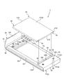
【解決手段】 本発明の天井パネル1は、建築物の構造材から垂下状態に設けられる吊持部材2(梁材8)によって天井付近に支持されるものであって、平面形状が矩形状を成す上下の表殻板3・4を具え、このうち下表殻板3は、例えばエンド側の二縁辺が室内天井面に相当する展開面部31に対して対向するように形成された上押さえ縁33を有し、この上押さえ縁33において、ボルト・ナット形式等の締結手段6により吊持部材2との取り付けを図るようにしたことを特徴とする。
【選択図】図1PROBLEM TO BE SOLVED: To develop a new ceiling panel that can securely and firmly support a lower surface shell plate in a ceiling panel, and can more reliably prevent peeling and dropping of the lower surface shell plate in an emergency such as a fire. Is an issue.
A ceiling panel 1 according to the present invention is supported near a ceiling by a suspension member 2 (beam member 8) provided in a suspended state from a structural material of a building, and has a rectangular planar shape. The upper and lower outer shell plates 3 and 4 are formed, and the lower outer shell plate 3 is, for example, an upper pressing edge formed such that two edges on the end side face the development surface portion 31 corresponding to the indoor ceiling surface. The upper holding edge 33 is attached to the suspension member 2 by a fastening means 6 such as a bolt / nut type.
[Selection] Figure 1
Description
本発明は、例えば冷凍・冷蔵倉庫等の天井面として施工される天井パネルに関するものであって、特に、該パネルの下表殻板が火災等の非常時において焼損により落下することを回避できるようにした新規な天井パネルに係るものである。 The present invention relates to a ceiling panel constructed as a ceiling surface of a freezing / refrigerated warehouse, for example, and in particular, it can be avoided that the lower shell plate of the panel falls due to burning in an emergency such as a fire. This relates to the new ceiling panel.
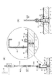
例えば天井パネルは、パネル内部に設けられた断熱素材を金属製の表殻板で上下から挟み込み(いわゆるサンドイッチ状)、上下方向に断熱性を持たせたものが普及している。この天井パネル1′の従来の一般的な支持構造は、例えば図13(a)に示すように、建築物自体の構造材である建屋梁Bからターンバックル機構91′を具えた連結部材9′を介して、断面C字状等の梁材(補強梁)8′を吊持し、この梁材8′に天井パネル1′を固定するものである。
For example, a ceiling panel in which a heat insulating material provided inside the panel is sandwiched from above and below by a metal shell plate (so-called sandwich shape) and has a heat insulating property in the vertical direction is widely used. For example, as shown in FIG. 13 (a), a conventional general support structure for the ceiling panel 1 'includes a connecting member 9' having a turnbuckle mechanism 91 'from a building beam B which is a structural material of the building itself. A beam member (reinforcing beam) 8 ′ having a C-shaped cross section is suspended through the, and the
すなわち、建屋梁Bから梁材8′を吊持するにあたっては、例えば上記図13(a)や図12(b)に示すように、ターンバックル機構91′の下部ネジボルト91D′に取り付けられた一対の吊り金具92′・93′によって、断面C字状を成す梁材8′の上片部を挟み付けるようにして梁材8′を吊持するものである。
また、この梁材8′に天井パネル1′を固定するにあたっては、一対のパネル固定金具81′・82′によって上記梁材8′を外側から抱え込むように係止させた状態で、このパネル固定金具81′・82′の上方からボルト63′等をネジ込む等して天井パネル1′を梁材8′に固定するものである。ここで、図中符号83′は、梁材8′とパネル固定金具82′との間に打ち込むクサビであり、これは両者の密着固定を強化し、天井パネル1′を確実に固定するためのものである。
That is, when suspending the beam 8 'from the building beam B, for example, as shown in FIGS. 13 (a) and 12 (b), a pair of screws attached to the
Further, when the ceiling panel 1 'is fixed to the beam member 8', the panel member is fixed in a state where the beam member 8 'is locked so as to be held from the outside by a pair of panel fixing brackets 81' and 82 '. The
このように天井パネル1′は、建屋梁Bからターンバックル機構91′や梁材8′等を介して支持(吊持)され、これにより天井パネル1′が室内の天井面として施工されるものである。
なお、天井パネル1′における妻面部32′には、例えば図13(a)の拡大図に示すように、各々の表殻板3′・4′の端縁を曲成した嵌込縁Fとし、この嵌込縁Fを別途アルミニウム製の型材等より成る妻面用接続片Jで連結し、妻面部32′をつなぐようにしている。
In this way, the ceiling panel 1 'is supported (suspended) from the building beam B via the turnbuckle mechanism 91', the beam member 8 ', etc., so that the ceiling panel 1' is constructed as an indoor ceiling surface. It is.
The end face 32 'of the ceiling panel 1' has, as shown in the enlarged view of FIG. The fitting edge F is separately connected by a connecting piece J for a face surface made of an aluminum mold or the like so as to connect the end face portion 32 '.
このような構造等から理解できるように、従来の天井パネル1′の支持(吊持)は、実質的に上表殻板4′を直に吊るものが多く、下表殻板3′には直接、支持力が作用しない吊持態様となっている。このため従来のパネル支持手法においては、火災が発生した場合、熱により天井パネル1′の下表殻板3′が剥がれて落下し、消火作業に支障をきたすことがあり、甚だしい場合には消火作業者の負傷等、重大な事故をも誘発することがあった。
As can be understood from such a structure and the like, the conventional support (suspension) of the
もちろん、上記以外のパネル支持手法としては、例えば図13(b)に示すように、天井パネル1′を吊持する支持力が下表殻板3′に作用するものもある。すなわち、図13(b)に示すものは、梁材8′が略逆T字状の断面形状を成すチャンネル材として形成され、この梁材8′の水平部分に天井パネル1′の下端縁を載せるようにした支持手法である(例えば特許文献1、2)。
因みに、本図13(b)では、略逆T字状断面を成す梁材8′の左右両側に、断面L字状のアングルピースMを設け、梁材8′の下端水平部とアングルピースMとの間では天井パネル1′を挟み込むようにしている。すなわち、この支持手法は、梁材8′の下端水平部に天井パネル1′を載せるように載置しながら、アングルピースMを設置した部位では、アングルピースMの上方から天井パネル1′をネジ留めする手法であり、天井パネル1′を下方から支持しながら同時に部分的な挟持も併用した手法と言える。
しかしながら、このような支持手法であっても天井パネル1′の支持、特に下表殻板3′の支持(保持)は、まだ不充分と考えられ、火災時等における下表殻板3′の剥離・落下をより完全に防止できる天井パネルが望まれていた。
Of course, as a panel support method other than the above, as shown in FIG. 13B, for example, there is a method in which a support force for suspending the ceiling panel 1 'acts on the lower shell plate 3'. That is, in the case shown in FIG. 13B, the beam member 8 'is formed as a channel member having a substantially inverted T-shaped cross section, and the lower edge of the ceiling panel 1' is formed on the horizontal portion of the beam member 8 '. This is a support method to be placed (for example,
Incidentally, in FIG. 13B, angle pieces M having an L-shaped cross section are provided on both left and right sides of the beam member 8 'having a substantially inverted T-shaped cross section, and the lower end horizontal portion of the beam member 8' and the angle piece M are provided. The ceiling panel 1 'is sandwiched between the two. That is, in this support method, the
However, even with such a support method, it is considered that the support of the
本発明は、このような背景を認識してなされたものであって、下表殻板を直接吊持することにより、下表殻板の支持を確実且つ強固なものとし、火災等の非常時においても下表殻板の剥離・落下をより確実に防止できるようにした新規な天井パネルの開発を技術課題とするものである。 The present invention has been made in view of such a background, and by directly suspending the lower shell plate, the support of the lower shell plate is ensured and strong, and in the event of an emergency such as a fire. The technical challenge is to develop a new ceiling panel that can more reliably prevent peeling and falling of the lower shell plate.
すなわち請求項1記載の天井パネルは、
建築物の構造材から垂下状態に設けられる吊持部材によって天井付近に支持される天井パネルにおいて、
この天井パネルは、平面形状が矩形状を呈する上下の表殻板を具えて成るものであり、
このうち下表殻板は、少なくとも対向する二縁辺が、室内天井面に相当する展開面部に対し上方に折り返し状に形成され、この折り返し部分において、前記吊持部材との取り付けを図るようにしたことを特徴として成るものである。
That is, the ceiling panel according to
In the ceiling panel supported near the ceiling by a suspension member provided in a suspended state from the structural material of the building,
This ceiling panel is composed of upper and lower outer shell plates having a rectangular planar shape,
Of these, the lower shell plate is formed so that at least two opposing edges are folded upward with respect to the development surface corresponding to the indoor ceiling surface, and the folded member is attached to the suspension member. It is characterized by this.
また請求項2記載の天井パネルは、前記請求項1記載の要件に加え、
前記下表殻板が吊持部材に取り付けられる部位は、展開面部に対してほぼ対向状態に折り返して形成された上押さえ縁であり、
この上押さえ縁と吊持部材とには、これらの固定を図るための締結用開口が各々対応した位置に形成され、
また天井パネルの内部には、締結手段の一方が設けられるものであり、
天井パネルを吊持部材に固定するにあたっては、前記締結手段により、上押さえ縁と吊持部材とに形成された締結用開口を通して下表殻板を吊持部材に固定するようにしたことを特徴として成るものである。
Moreover, in addition to the requirements of
The site where the lower shell plate is attached to the suspension member is an upper holding edge formed by folding back in a substantially opposite state with respect to the development surface portion,
The upper pressing edge and the suspension member are formed with fastening openings for fixing them at corresponding positions,
One of the fastening means is provided inside the ceiling panel,
When fixing the ceiling panel to the suspension member, the lower shell plate is fixed to the suspension member through the fastening opening formed in the upper pressing edge and the suspension member by the fastening means. It consists of
また請求項3記載の天井パネルは、前記請求項2記載の要件に加え、
前記上押さえ縁を下表殻板の展開面部に対してほぼ対向状態に形成するにあたっては、展開面部から、ほぼ直角に立ち上がるように形成された妻面部に対し、更にその上端縁から展開面部に沿うようにほぼ直角に内曲げして、上押さえ縁を形成するようにしたことを特徴として成るものである。
Moreover, in addition to the requirement of the said
In forming the upper pressing edge substantially opposite to the development surface portion of the lower shell plate, the upper surface edge is further extended from the development surface portion to the development surface portion with respect to the wife surface portion formed so as to rise substantially at a right angle. It is characterized in that it is bent inward substantially at right angles so as to form an upper pressing edge.
また請求項4記載の天井パネルは、前記請求項2または3記載の要件に加え、
前記天井パネルの取り付けにあたっては、締結手段が下表殻板の上押さえ縁を貫通することに加え、上表殻板も貫通して下表殻板を吊持部材に固定するようにしたことを特徴として成るものである。
Further, the ceiling panel according to
In attaching the ceiling panel, the fastening means penetrates the upper pressing edge of the lower surface shell plate, and the upper surface shell plate also penetrates to fix the lower surface shell plate to the suspension member. It consists of features.
また請求項5記載の天井パネルは、前記請求項2、3または4記載の要件に加え、
前記締結手段の一方を天井パネルの内部に設けるにあたっては、当該締結手段と表殻板とが直接接触しないようにヒートインシュレータが設けられることを特徴として成るものである。
Further, the ceiling panel according to
When one of the fastening means is provided inside the ceiling panel, a heat insulator is provided so that the fastening means and the outer shell plate are not in direct contact with each other.
また請求項6記載の天井パネルは、前記請求項5記載の要件に加え、
前記上押さえ縁において締結手段による締結を受ける部位は、上押さえ縁の上側に、更に断熱性の部材が設けられることを特徴として成るものである。
Moreover, in addition to the requirements of
The portion of the upper pressing edge that is fastened by the fastening means is characterized in that a heat insulating member is further provided on the upper side of the upper pressing edge.
また請求項7記載の天井パネルは、前記請求項2、3、4、5または6記載の要件に加え、
前記下表殻板の上押さえ縁と、吊持部材との締結は、ボルトとナットとを適用した螺合であることを特徴として成るものである。
The ceiling panel according to claim 7 is in addition to the requirement according to
The fastening of the upper pressing edge of the lower outer shell plate and the suspension member is a screw engagement using bolts and nuts.
また請求項8記載の天井パネルは、前記請求項7記載の要件に加え、
前記天井パネルの内部に設けられる締結手段は、ナットであることを特徴として成るものである。
Further, the ceiling panel according to
The fastening means provided inside the ceiling panel is a nut.
また請求項9記載の天井パネルは、前記請求項8記載の要件に加え、
前記ナットは、メネジが形成される水平部と、この水平部に対しほぼ直角に折り曲げ形成される垂直部とを具えた板ナットであり、この垂直部が天井パネルの内部で固定されることを特徴として成るものである。
The ceiling panel according to
The nut is a plate nut having a horizontal part in which a female screw is formed and a vertical part that is bent at a substantially right angle to the horizontal part, and the vertical part is fixed inside the ceiling panel. It consists of features.
また請求項10記載の天井パネルは、前記請求項3、4、5、6、7、8または9記載の要件に加え、
前記上押さえ縁が連続形成される一対の妻面部以外の他の一対の面には、妻面部にほぼ直交する方向に一対の骨枠材が設けられ、
このうち一方の骨枠材には、隣り合うパネル同士を接続するオスザネが形成され、もう一方の骨枠材には、このオスザネに嵌まるメスザネが形成されることを特徴として成るものである。
Further, the ceiling panel according to claim 10 is in addition to the requirement according to
The pair of other surfaces other than the pair of wife face portions in which the upper pressing edge is continuously formed is provided with a pair of bone frame members in a direction substantially orthogonal to the wife face portion,
Of these, one bone frame material is formed with a male zane that connects adjacent panels, and the other bone frame material is formed with a female zane that fits into this male zane.
これら各請求項記載の発明の構成を手段として前記課題の解決が図られる。
まず請求項1記載の発明によれば、天井パネルを吊持部材に固定するにあたり、下表殻板の展開面部から上方に折り返した部位で吊持部材との取り付けを図るため、下表殻板を吊持部材に対し、直接且つ強固に固定することができ、例えば火災による熱損傷を受けても下表殻板が落下してしまうことを防止できる。
また、下表殻板(展開面部)から上方に折り返した部位で吊持部材との固定を図るため、例えば隣り合う二つの天井パネルを、一つの吊持部材(梁材)で一挙に吊る場合でも、天井パネルの収まりが良く(見栄えが良く)、またボルトやナット等の締結手段が天井パネルの合わせを阻害することも防止できる。
The above-described problems can be solved by using the configuration of the invention described in each of the claims.
First, according to the first aspect of the present invention, when the ceiling panel is fixed to the suspension member, the lower surface shell plate is attached to the suspension member at a portion folded upward from the development surface portion of the lower surface shell plate. Can be directly and firmly fixed to the suspension member, and for example, the lower outer shell plate can be prevented from falling even if it is damaged by heat.
Also, for example, when two adjacent ceiling panels are suspended at once by one suspension member (beam material) in order to secure the suspension member at a portion folded upward from the lower surface shell plate (deployment surface). However, the ceiling panel fits well (looks good), and fastening means such as bolts and nuts can also prevent the ceiling panel from being obstructed.
また請求項2記載の発明によれば、例えば下表殻板に対してほぼ対向状態に形成される上押さえ縁において吊持部材との固定を図るなど、天井パネルを吊持部材に対しどのように固定するのかをより具体的なものとする。 According to the second aspect of the present invention, the ceiling panel is fixed to the suspension member by, for example, fixing the suspension panel to the suspension member at the upper holding edge formed substantially opposite to the lower shell plate. It will be more specific whether it is fixed to.
また請求項3記載の発明によれば、下表殻板の展開面部からほぼ直角に立ち上がるように妻面部が形成され、更にこの妻面部からほぼ直角に内曲げされて、前記上押さえ縁が連続形成されるため、妻面部がフラットな立ち上がり面として形成され、例えば隣り合う二つの天井パネルを、一つの吊持部材(梁材)で一挙に吊る場合、天井パネルをより一層見栄え良く収めることができる。 According to the third aspect of the present invention, the end face portion is formed so as to rise substantially at a right angle from the developed surface portion of the lower shell plate, and is further bent inwardly at a substantially right angle from the end face portion so that the upper pressing edge is continuous. Because it is formed, the end face part is formed as a flat rising surface. For example, when two adjacent ceiling panels are suspended at once by one suspension member (beam material), the ceiling panel can be further enhanced in appearance. it can.
また請求項4記載の発明によれば、天井パネルの取り付けにあたり、ボルト等の締結手段が、下表殻体(上押さえ縁)だけでなく、上表殻体をも貫通するため、天井パネルの吊持部材(梁材)への固定や下表殻板の支持を、より一層強化することができる。
According to the invention described in
また請求項5記載の発明によれば、天井パネルの内部に設けられるナット等の締結手段と、下表殻板における上押さえ縁との間には、ヒートインシュレータを介在させるため、締結手段と上押さえ縁とを熱絶縁状態で維持することができる。従って、天井パネルに断熱性が要求される場合に、例えば室内空間の熱が、下表殻板の展開面部から上押さえ縁まで伝わっても、ナット等の締結手段には熱が伝わらないものである。つまり、天井パネルの内部に設けたナット等の締結手段が、熱橋(ヒートブリッジ)となって天井パネルの断熱効果を低下(悪化)させてしまうことがないものである。
また、ヒートインシュレータによって上押さえ縁から締結手段への伝熱が防止できることは、一旦、締結した締結手段の熱変形(熱膨張)も防げることになり、これに起因する締結手段の弛みや締結力の低下なども防止できる。
According to the invention described in
In addition, the fact that heat transfer from the upper holding edge to the fastening means can be prevented by the heat insulator can also prevent thermal deformation (thermal expansion) of the fastening means once fastened, resulting in loosening and fastening force of the fastening means. It is also possible to prevent a decrease in the level.
また請求項6記載の発明によれば、上押さえ縁において締結手段による締結を受ける部位は、断熱性を有する部材によって上下方向から挟み込まれるため、上記のようにたとえ上押さえ縁が熱を持ったとしても、この熱が上表殻板や、天井パネルの内部に設けたナットに伝わることがないものである。
According to the invention described in
また請求項7記載の発明によれば、天井パネルを吊持部材に固定する際、極めて一般的なボルト・ナット形式の締結手段を適用するため、施工者(職人)も扱い慣れており、確実且つ効率的な施工・取り付けが行える。 Further, according to the invention described in claim 7, when a ceiling panel is fixed to the suspension member, a very general bolt / nut type fastening means is applied, so that a builder (craftsman) is used and is surely sure. In addition, efficient installation and installation can be performed.
また請求項8記載の発明によれば、天井パネルの内部に設けられる締結手段がナットであるため、天井パネルの上部がほぼフラットになり、ボルトのオネジ部が天井パネルから突き出ることがない。従って天井パネルを施工現場に搬入する場合や、製造後に倉庫等で保管する場合、あるいは施工現場において実作業に取り掛かるまでの仮置き等において、天井パネルの取り扱いが極めて行い易く、便利である。もちろん施工現場等においては、ボルト先端部等の飛び出しがないことから、例えば職人が作業服等を引っ掛けてしまう心配もなく、施工がよりスムーズに行えるものである。 According to the eighth aspect of the present invention, since the fastening means provided inside the ceiling panel is a nut, the upper portion of the ceiling panel is substantially flat, and the male screw portion of the bolt does not protrude from the ceiling panel. Therefore, when the ceiling panel is carried into the construction site, stored in a warehouse after production, or temporarily placed until actual work is started at the construction site, the ceiling panel is extremely easy to handle and convenient. Of course, since there is no protrusion of the bolt tip or the like at the construction site or the like, for example, there is no concern that the craftsman will hook the work clothes or the like, and the construction can be performed more smoothly.
また請求項9記載の発明によれば、メネジが切られた水平部に対してほぼ90度に折り曲げて成る垂直部を、天井パネルの内部に固定するため、天井パネルの上方からボルトをネジ込んだ際にナットが共回りしてしまうことを確実に防止でき、着実に天井パネルを吊持部材(梁材)に固定することができる。 According to the ninth aspect of the present invention, a bolt is screwed from above the ceiling panel in order to fix the vertical portion, which is bent at about 90 degrees with respect to the horizontal portion where the female thread is cut, to the inside of the ceiling panel. In this case, the nut can be reliably prevented from rotating together, and the ceiling panel can be steadily fixed to the suspension member (beam member).
また請求項10記載の発明によれば、妻面部とほぼ直交するサイド端の一方に、オスザネを有した骨枠材を設け、もう一方にメスザネを有した骨枠材を対向状態に設けるため、隣り合う天井パネルにおけるサイド端同士の接続が、上記サネ構造によって確実に行える。 Further, according to the invention of claim 10, in order to provide a bone frame material having a male zane on one of the side ends substantially orthogonal to the wife face portion, and to provide a bone frame material having a female zane on the other side, The side ends of adjacent ceiling panels can be reliably connected to each other by the above-described frame structure.
本発明を実施するための形態は、以下の実施例に述べるものをその一つとするとともに、更にその技術思想内において改良し得る種々の手法を含むものである。 The mode for carrying out the present invention includes one described in the following embodiments, and further includes various methods that can be improved within the technical idea.
本発明は、例えば上下で対を成す表殻板3・4の間に断熱材5をサンドイッチ状に収納して成る天井パネル1に関するものであり、上下の表殻板3・4は平面視形状が矩形状を成し、また素材としてはアルミニウム等の金属素材で形成される。
因みに、このような天井パネル1は、室内空間の天井面としてそのまま使用(施工)されることが多く、本明細書でもこのような態様(仕様)を基本とする。また、本発明の天井パネル1が天井面として施工される室(部屋)の例としては、断熱性が要求される冷凍・冷蔵倉庫、物流倉庫、恒温室、パソコンルーム、食品工業用クリーンルーム等が挙げられる。
The present invention relates to a
Incidentally, such a
ここで天井パネル1の一般的な支持構造(固定状況)について概略的に説明しておく。
天井パネル1は、建築物自体の梁や桁など建築物そのものの構造材(本明細書ではこれを「建屋梁B」とする)から垂下状態に設けられる吊持部材2に保持・固定されるものであり、これにより室内の天井面として施工される。
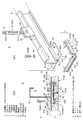
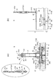
吊持部材2は、一例として図1に示すように、ほぼC字状の断面形状を成す梁材(補強梁)8を主要部材とし、この梁材8に天井パネル1を固定し、吊持するものである。この際、建築物そのものの構造材である建屋梁Bと、天井パネル1を固定するための梁材8との間には、ターンバックル機構91を具えた連結部材9を介在させるものであり、これは天井パネル1の吊り高さを調整するためである。また、このため上記吊持部材2としては、天井パネル1を固定するための梁材8に加え、ターンバックル機構91を具えた連結部材9も含むものとする。
Here, a general support structure (fixed state) of the
The
As shown in FIG. 1 as an example, the
そして、本発明では、平面視矩形状を成す下表殻板3の四縁辺のうち、少なくとも対向する二縁辺を上方に折り返すように形成し、この上方折り返し部で吊持部材2との直接固定(吊持)を図るものである。このため本発明では、天井パネル1における特に下表殻板3を吊持部材2に強固に固定(緊結)することができ、堅固な支持固定が実現できる。このため万一、火災が起きても、下表殻板3が熱損傷によって剥離・落下してしまうことがなく、これが本発明の大きな特徴である。
なお、本明細書では天井パネル1を梁材8(吊持部材2)に固定する構造を支持構造Sとするものであり、この支持構造Sは、天井パネル1そのものに加え、吊持部材2を含む概念とし、以下、これら天井パネル1と吊持部材2とについて説明する。
And in this invention, it forms so that at least two opposing sides may be folded up among the four edges of the lower
In this specification, the structure for fixing the
天井パネル1は、例えば上述したように断熱材5を金属製の表殻板3・4で上下からサンドイッチ状に挟み込むように収納して、上下方向に断熱効果を持たせたパネルであり、このものは一例として図1〜図4に示すように、下表殻板3と上表殻板4と断熱材5とを具えて成る。
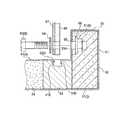
ここで上記実施例では図示のように、天井パネル1の内部、特にここでは断熱材5の一部に、締結手段6としてのナット61(特にここでは板ナットを基本とする)を固定状態に設けるものであり、これは梁材8に係止したパネル固定金具81・82の上方からボルト63をネジ込むことにより、天井パネル1を梁材8(吊持部材2)に固定するためである。このように、本発明においては天井パネル1の内部に締結手段6の一方を固定状態に設けるものであり、これに因み天井パネル1は、上下の表殻板3・4及び断熱材5に加え、締結手段6をも含めた概念とする。
The
Here, in the above-described embodiment, as shown in the drawing, a nut 61 (in particular, a plate nut here) is fixed in the interior of the
なお、天井パネル1の内部には、通常、上記のような断熱材5を収容し、パネルの上下方向に断熱性を持たせたものが多いため、本明細書でも天井パネル1の内部に断熱材5を収める形態を前提として説明する。しかしながら、本発明の主目的は、上記のように万一、火災が起きても、天井パネル1における下表殻板3が熱損傷によって剥離・落下してしまうことを防止することである。従って天井パネル1においては必ずしも断熱性は必要ではなく、そのため本発明の天井パネル1としては上記断熱材5を省略することもできるし、当該断熱材5を非断熱性の素材、具体的には適宜の長さにカットした金属製の角パイプ材などで代用することも可能である。もちろん、このような場合には「断熱材」という名称はそぐわないかも知れないが、本明細書では一般的な天井パネル1の構造に基づき、パネル内に収容されることが多い収容物を「断熱材」と称したものである。因みに、断熱性を前提とした天井パネル1は、「断熱天井パネル」と称されることも多い。
In many cases, the
また、本実施例における断熱材5は、基本的に複数のパーツ(これを断熱材要素とする)を組み合わせて成る集合体であることから、当該断熱材を「断熱集合体」と称することもある。また以下の説明では、天井パネル1を構成する各部材の詳細な説明に先立ち、まず表殻板3・4と断熱集合体5の概略構成について説明する。
上下の表殻板3・4は、断熱集合体5を所定の状態(規則的な状態)で収容する言わばケーシング(収納ケース)として形成される。特に本実施例では、一例として図3・4に示すように、下表殻板3を角皿状と表現できるような容器状に形成し、ここに断熱集合体5を規則的に収めた後、上表殻板4で蓋をするような構成を採る。
In addition, since the
The upper and lower
以下、下表殻板3について更に説明する。
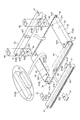
下表殻板3は、例えば図4に示すように、一枚の金属板材(ブランク材)から立体的に折り曲げ形成されるものであり、施工状態で室内空間の天井面となり、且つ断熱集合体5を収めるケーシングの底部となる展開面部31と、この展開面部31の少なくとも対向する二縁辺を展開面部31から上向きにほぼ直角に折り曲げて形成される妻面部32と、この妻面部32の上端縁から展開面部31に対してほぼ対向状態(ほぼ平行状態)に内曲げ形成される上押さえ縁33とを具えて成るものである。
ここで天井パネル1や立体的に形成された下表殻板3を平面から視た場合に、上押さえ縁33が形成される二縁辺(妻面部32)を「エンド側」または「エンド端」と定義し、上押さえ縁33や妻面部32に直交する残余の二縁辺を「サイド側」または「サイド端」と定義する。
因みに、天井パネル1(下表殻板3)は、サイド側の長さ(一方のエンド端から他方のエンド端までの長さ)がエンド側よりも長く形成され、例えばエンド側の長さは約900mmが標準寸法であるのに対し、サイド側の長さは約1800mmまたは2700mmが標準寸法として形成される。このように天井パネル1は、サイド側がエンド側よりも長く形成されるのが一般的であり、このため上記「サイド」とは天井パネル1や立体的な下表殻板3における長手方向を意味し、「エンド」とは短手方向を意味するものでもある。
Hereinafter, the
For example, as shown in FIG. 4, the lower
Here, when the
Incidentally, the ceiling panel 1 (the lower shell plate 3) is formed such that the side length (the length from one end end to the other end end) is longer than the end side. About 900 mm is the standard dimension, while the side length is about 1800 mm or 2700 mm. Thus, the
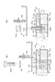
そして、前記上押さえ縁33と展開面部31との間には、例えば図3に示すように、妻面部32もしくはエンド端に沿って、細長い二本の直方体状の断熱材要素を収容するものである。この断熱材要素には、長いものと短いものとがあり、長い方がエンド端寄りに設けられ、これを「エンド断熱材要素51」とし、このものは上押さえ縁33とほぼ同じ長さ(エンド方向の長さ)に形成される。一方、これよりも短い方がその隣(センター寄り)に設けられ、これを「エンド断熱材要素52」とする。
ここでエンド断熱材要素52をエンド断熱材要素51よりも短く形成したのは、締結手段6としてのナット61等を天井パネル1の内部に設けるためである。
なお、本実施例ではエンド断熱材要素51・52を別々の棒状部材として形成したが、必ずしもその必要はなく、双方の厚み寸法(高さ寸法)がほぼ同じであることから、一定厚みを有する板状の断熱材からエンド断熱材要素51・52を合わせて、一挙に切り出すことも可能である。
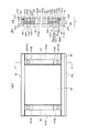
And between the said upper pressing
The reason why the end heat insulating
In this embodiment, the end
また、立体的に形成された下表殻板3の両サイドには、このサイド端に沿うように、つまり妻面部32に直交するように、別の細長い断熱材要素が収められるものであり、これをサイド骨枠材53とする。このような構成に因み、展開面部31の両サイド端には上方に向かう折り返し部31Sが形成され、この折り返し部31Sにより当該サイド骨枠材53がサイド端に沿って綺麗に収容されるものである。
なお、サイド骨枠材53の厚み寸法(高さ寸法)は、一例として図2(b)・図3に示すように、展開面部31から上押さえ縁33までの間隔寸法よりも大きく形成され、上記エンド断熱材要素51・52よりも大きな厚み寸法を有する。このためサイド骨枠材53の上面は、収納状態で上押さえ縁33よりも上方に位置するものである。従って、上押さえ縁33の両サイド端は、サイド骨枠材53との干渉を避けるように一部、切欠き状に形成されており、ここを干渉回避部34とする。また、この干渉回避部34は、妻面部32にも形成されている。
因みに、断熱集合体5の一構成要素であるサイド骨枠材53を「断熱材(要素)」ではなく「骨枠材」と称したのは、このものが断熱機能を有すると同時に、他の断熱材要素よりも硬い素材で形成され、天井パネル1の強度(フレーム強度)、特に当該パネルのサイド方向もしくは長手方向の強度アップを担っているためである。
Further, on both sides of the lower
In addition, the thickness dimension (height dimension) of the side
Incidentally, the side
ここで断熱集合体5について総括的に説明する。
断熱集合体5は、上述したようにエンド断熱材要素51・52とサイド骨枠材53を具える他、一例として図3・4に示すように、これらによって取り囲まれるほぼ中央部にセンター断熱材要素54を具えて成るものである。
なお、センター断熱材要素54の厚み(高さ)も、サイド骨枠材53とほぼ同じ厚み寸法に形成されるため、センター断熱材要素54もサイド骨枠材53と同様に、収納状態で上面が上押さえ縁33よりも上方に位置するものである。
Here, the
The
In addition, since the thickness (height) of the center heat insulating
また、左右一対のサイド骨枠材53には、隣接する天井パネル1同士(接触するサイド端同士)を接続するためのサネ(実)が形成される。具体的には二つのサイド骨枠材53のうち一方(図3では右奥側)のサイド端長手方向に溝状のメスザネ(雌実)53Tが形成されるとともに、他方のサイド骨枠材53(図3では左手前側)のサイド端長手方向に凸状のオスザネ(雄実)53tが形成されるものであり、これらメスザネ53Tとオスザネ53tとの嵌め合いによって、隣り合う天井パネル1同士が接続されるものである。
なお図1(b)や図5では、上記隣接する天井パネル1の隙間にコーキング処理が施されており、これはコーキング剤の充填により当該隙間をシールする手法であり、主として目的の部屋(室内)に気密性が要求される場合に施される処理である(単に隙間を隠すという見栄え向上の目的で施されることもある)。しかし、このようなコーキング処理は実際には手間の掛かる作業であり、このため上記サネ構造の嵌め合い部分にパッキンを噛ませ、隣接する天井パネル1を押し込むだけで気密が保てるようにすることもでき、これに適したオスザネ53tの形状が、例えば図2(b)や図3に示すように、オスザネ53tの先端部を凹陥状に形成した形状である。すなわち、先端部が凹陥状に形成されたオスザネ53tは、気密性を目的としたコーキング処理を不要とするための構造と言える。
Moreover, the pair of left and right side
In FIG. 1B and FIG. 5, a caulking process is performed on the gap between the
また本実施例では、上述したようにボルト・ナット形式の締結手段6により、天井パネル1を梁材8に固定するものであり、このためサイド骨枠材53には、ナット61(板ナット)を固定状態に取り付けるものである。
ここでナット61は、一例として図2(b)・図3に示すように、メネジが切られるほぼ水平な水平部61Hから、ほぼ90度折り曲げられた垂直部61Vを有するように形成され、この垂直部61Vがサイド骨枠材53の側部にネジ留め等によって固定される。もちろん、ナット61は、水平部61H(メネジ部)が天井パネル1の内側(ここではエンド断熱材要素52)に張り出すように、サイド骨枠材53に取り付けられるものである。
In the present embodiment, as described above, the
Here, as an example, as shown in FIGS. 2B and 3, the
また下表殻板3の上押さえ縁33や上表殻板4あるいはパネル固定金具81・82には、ボルト63を通すための締結用開口33H・41H・81H・82Hを形成しておくものであり、これを利用してパネル固定金具81・82の上方からボルト63を差し込み、サイド骨枠材53に固定したナット61と螺合させることで、天井パネル1を梁材8に固定するものである。
なお、図1・2中の符号64は、ボルト63をパネル固定金具81・82の上からネジ込む際に使用されるワッシャ(座金)である。
因みに、図3では上押さえ縁33の締結用開口33Hを円形つまり円孔として図示しているが、この締結用開口33Hは、必ずしも円形等の孔状に限定されるものではなく、例えば図4(b)に示すように、切欠き状に形成することも可能である。
Also, fastening holes 33H, 41H, 81H, and 82H for passing
In addition, the code |
Incidentally, in FIG. 3, the
次に、サイド骨枠材53に取り付けられるナット61の固定状況(設置状況)について説明する。本実施例では、上述したようにナット61をネジ留め等によりサイド骨枠材53に固定するものであり、これはボルト63をネジ込む際、ナット61が回転してしまうこと(共回り)を防止するためである。
またナット61の上部、つまりナット61と上押さえ縁33との間には、ヒートインシュレータ65を介在させるものであり、これはナット61と上押さえ縁33とが直接接触しないようにするためであり、言わば熱絶縁のためである。これにより例えば下表殻板3の展開面部31が室内空間の熱により温められ、この熱が妻面部32を通して上押さえ縁33に伝わっても、ナット61はヒートインシュレータ65によって上押さえ縁33から隔離(熱絶縁)されているため、上押さえ縁33からナット61に熱が伝わることはないものである。従って、天井パネル1に断熱性が要求される場合には、パネル内部(サイド骨枠材53)に固定したナット61が、熱橋(ヒートブリッジ)となって天井パネル1の断熱効果(室内の断熱)を低下(悪化)させてしまうことがなく、高い断熱性能が確保できるものである。
なお、ヒートインシュレータ65によってナット61等の締結手段6への伝熱を阻止する上記構成は、ナット61自体の熱変形(熱膨張)も防げるため、これに起因する弛みや締結力の低下なども防止できるものである。
因みにヒートインシュレータ65は、接着剤等によってナット61の上面に一体的に接合される(取り付けられる)ものである。
Next, a fixing state (installation state) of the
Further, a
Note that the above-described configuration in which the
Incidentally, the
またナット61の下部には、一例として図2(b)や図3に示すように、ナット61の水平部61Hを支持するナット受け材62が設けられ、このものも断熱性の素材で形成される。これは下表殻板3の展開面部31が室内空間の熱により温められた場合、この熱がナット61に伝わることを防止するためである。
このナット受け材62は、ほぼ直方体状に形成され、その平面視形状は、ナット61の水平部61Hとほぼ同じ形状である。また、ナット受け材62には、ボルト63をナット61にネジ込んだ際の底付きを防止するための空間(これを底付き防止部62Eとする)が形成される。
Further, as shown in FIG. 2B and FIG. 3 as an example, a
The
次に上表殻板4について説明する。上表殻板4は、上述したように収納ケースとなる下表殻板3に断熱集合体5を規則的に収めた後、この状態を維持するように、その上方から被せる蓋部材の作用を担うものである。
この上表殻板4は、一例として図4に示すように、下表殻体3の展開面部31とほぼ同じ平面視形状を有する天面部41を本体部として具える。そして、この天面部41におけるエンド側の底面には、下表殻体3の上押さえ縁33に接触する上押さえ材42が貼設され、下表殻体3(断熱集合体5を収めた状態)に上表殻板4を被せた際には、上押さえ材42が上押さえ縁33を上方から押さえ込む、もしくは押し付けるように構成される。もちろん、上押さえ材42は、サイド骨枠材53やセンター断熱材要素54と干渉しないように設けられるものである。
なお、この上押さえ材42も断熱性を有する素材で形成されるものであり、これにより、たとえ上押さえ縁33が熱を持ったとしても、この熱が上表殻板4に伝わることはないものである。また、このような構成上、上押さえ縁33は、図2(b)に示すように、上下方向から共に断熱性を有する上押さえ材42とヒートインシュレータ65とによって挟持されるものである。
Next, the
As shown in FIG. 4 as an example, the upper
The upper pressing
以下、上押さえ材42について更に説明する。
上押さえ材42の厚み寸法(高さ寸法)は、一例として図1(b)や図2(b)に示すように、サイド骨枠材53やセンター断熱材要素54が上押さえ縁33から突出する寸法とほぼ同じである。
また、上押さえ材42は、上記図1(b)・図4に併せ示すように、エンド側の下端縁が一部、切り欠き状に形成されており(ここを嵌合材受入部Rとする)、これは隣り合う天井パネル1同士をエンド端で接続する際、平板状のパネル嵌合材PJを嵌めて接続するためである。すなわち、室内天井として隣り合う天井パネル1同士を接続するにあたり、エンド側では上記図1(b)に示すように、細長い平板状のパネル嵌合材PJを嵌めて天井パネル1同士の接続を図るものである。このため、一つの上押さえ材42に形成される嵌合材受入部Rは、パネル嵌合材PJの約半分程度の幅寸法に形成されるものである。なお、天井パネル1同士のサイド側での接続は、上述したようにサイド骨枠材53に形成されているサネ構造、つまりメスザネ53Tとオスザネ53tとの嵌め合いにより接続を図るものである。
Hereinafter, the upper pressing
For example, as shown in FIGS. 1B and 2B, the thickness dimension (height dimension) of the upper pressing
Further, as shown in FIGS. 1 (b) and 4 above, the upper pressing
そして、このような嵌合材受入部Rは、例えば図3に示すように、サイド骨枠材53にも形成される。因みにサイド骨枠材53は、上述したように比較的長い部材である。従って、このような長い部材の両端を一部切り欠いて(切削して)、上記のような嵌合材受入部Rを形成することが加工上難しいことも考えられる。このため、その場合には、例えばサイド骨枠材53を中央部とその両端部分とに三分割する構成とし、短寸状となった両端部分に嵌合材受入部Rを形成した後、下表殻板3に収める際に、これらを直列状に並べるように収容することも可能である。
因みに、パネル嵌合材PJは、例えば耐熱性を有する合成樹脂等の素材で形成されることが好ましい。
And such a fitting material receiving part R is formed also in the side
Incidentally, the panel fitting material PJ is preferably formed of a material such as a heat-resistant synthetic resin.
また本実施例では、上記図1(b)に併せ示すように、上押さえ縁33の上方では、上表殻板4が上押さえ縁33にオーバーラップするように設けられるため、ボルト63は、下表殻体3だけでなく上表殻体4をも貫通することになる。このため、上表殻板4の天面部41や上押さえ材42にも締結用開口41H・42Hが形成される。なお、ボルト63が下表殻体3だけでなく上表殻体4も貫通することにより、天井パネル1の固定ひいては下表殻板3の支持が、より一層強化されるものである。
Further, in this embodiment, as shown in FIG. 1 (b), the
また、上表殻板4の天面部41にはサイド端及びエンド端において下向きの折り返しが形成され(図4参照)、サイド側の折り返し部41Sは、図2(b)に示すようにサイド骨枠材53に係止し、サイド骨枠材53を収納状態で保持・維持するものであり、エンド側の折り返し部41Eは、図4に示すように、天面部41の底面に貼設される上押さえ材42に係止し、上押さえ材42を貼設する際の端部押さえとして作用する。
なお、断熱集合体5を収めた下表殻板3に対し、上表殻板4を蓋部材として取付固定するにあたっては、例えば上表殻板4のサイド端縁にタッピングスクリューを打ち込み、当該スクリューをサイド骨枠材53までネジ込むことで固定することができる(図9(a)参照)。
Further, the
In attaching and fixing the upper
次に吊持部材2について説明する。吊持部材2は、上述したように例えば略C字状断面を成す梁材8を主要部材とし、当該梁材8と建屋梁Bとをつなぐ連結部材9も含むものである。以下、これら梁材8と連結部材9とについて説明する。
梁材8は、天井パネル1を直に支持する部材であり、これには一例として図1に示すように、一対のパネル固定金具81・82が使用される。この一対のパネル固定金具81・82は、エンド側において隣り合う各々の天井パネル1を梁材8に固定するものであり、一つ目のパネル固定金具81(図1(b)において左側のもの)は、概ねクランク状の断面を有するものである。そして、このパネル固定金具81は、断面C字状を成す梁材8の外側に係止するように取り付けられる。より詳細には、当該パネル固定金具81の上方略水平部と略垂直部とを、梁材8の上片部及び垂直部を外側から抱え込むように係止させた後、当該パネル固定金具81の下方略水平部を天井パネル1(図1(b)における左側のパネル)の上表殻板4に密着させ、この状態で当該パネル固定金具81の上方からボルト63等をネジ込んで、当該天井パネル1を梁材8に固定するものである。ここで図中符号81H(82H)は、上述したようにパネル固定金具81(82)に形成された締結用開口である。
Next, the
The
一方、二つ目のパネル固定金具82(図1(b)において右側のもの)は、先端にフック状の係止部を具えながら全体的に偏平状を成すものであり、その係止部を断面C字状を成す梁材8の下片部(折り返し)に係止させた状態で、当該パネル固定金具82の他端水平部を天井パネル1(図1(b)における右側のパネル)の上表殻板4に密着させ、当該パネル固定金具82の上方からボルト63等をネジ込んで、当該天井パネル1を梁材8に固定するものである。
なお、二つ目のパネル固定金具82の係止部と梁材8との間には、これらの密着固定を強化するためにクサビ83が打ち込まれるものである(図12(b)参照)。
On the other hand, the second panel fixing bracket 82 (on the right side in FIG. 1 (b)) has a hook-shaped locking portion at the tip, and has a flat shape as a whole. With the other end horizontal portion of the
In addition, a
次に連結部材9について説明する。連結部材9は、上述したように建築物自体の構造材である建屋梁Bと、天井パネル1が固定される梁材8とを中継接続する部材であり、一例として図1(a)に示すように、上部ネジボルト91Uと下部ネジボルト91Dとをターンバックル91Tで連結したターンバックル機構91を主な構成部材とする。また下部ネジボルト91Dの下端部には一対の吊り金具92・93が設けられ、この吊り金具92・93を、断面C字状を成す梁材8の上片部に掛止させ(挟持状態の掛止)、梁材8を吊持するものである。因みに、梁材8に対する吊り金具92・93の設置位置は、パネル固定金具81・82の設置位置とは異なる位置に設定され、双方が干渉しないように考慮されている。
Next, the connecting
なお、連結部材9にターンバックル機構91を組み込むのは、天井パネル1の吊り高さを適宜、調整可能とするためである。すなわち、例えばターンバックル91Tの上部に螺嵌される上部ネジボルト91Uには右ネジを形成する一方、ターンバックル91Tの下部に螺嵌される下部ネジボルト91Dには左ネジ(逆ネジ)を形成するものであり、これによりターンバックル91Tを正転または逆転させた場合に、双方のネジボルト91U・91Dが互いに接近または離反するものであり、かかる構成により天井パネル1の上下位置を調整することができるものである。
The reason why the
本発明の天井パネル1は、以上のような基本構造を有するものであり、以下、当該天井パネル1を梁材8に固定する取付態様(吊持態様)について説明する。
天井パネル1を梁材8に固定するにあたっては、まず一対のパネル固定金具81・82を梁材8に係止させるものであり、その後、このパネル固定金具81・82の上方から、ワッシャ64を介してボルト63を各々の締結用開口81H・82Hからネジ込むものである。
ここで天井パネル1の内部(サイド骨枠材53)には、このボルト63(締結用開口81H・82H)に対応した位置に、ナット61が動かないように固定されているため、上記ボルト63のネジ込み操作中に、ナット61が回転(共回り)してしまうことがなく、ボルト63のネジ込み操作が確実に行えるものである。
The
In fixing the
Here, since the
また、ナット61と上押さえ縁33との間には、図1(b)・図2(b)に示すように、これらが直接接触しないように、ヒートインシュレータ65が設けられる。これによりナット61は、上押さえ縁33に対して熱絶縁状態が維持されており、例えば室内側の熱が、室内天井面となる展開面部31から、これに連続して形成される妻面部32、そして上押さえ縁33へと伝わっても、上押さえ縁33からナット61に熱が伝わることはないものである。つまり天井パネル1に断熱性が要求される場合には、ナット61が熱橋(ヒートブリッジ)となって天井パネル1の断熱機能(室内の断熱効果)を低下させてしまうことがなく、高い断熱性能が得られるものである。もちろん、このような熱絶縁機能の維持・向上は、展開面部31とナット61との間に設けられる断熱性のナット受け材62についても言えることである。
Further, as shown in FIGS. 1B and 2B, a
また本実施例では、上押さえ縁33の上部にも断熱素材で形成された上押さえ材42を設けるため、上押さえ縁33は上下が断熱性の素材で挟持されることになる。これにより上押さえ縁33と梁材8(もしくは上表殻板4)との間においても熱絶縁状態が維持されることになり、上記のようにたとえ上押さえ縁33が熱を持っても、この熱が上押さえ縁33から梁材8(もしくは上表殻板4)に伝わることはないものである。これにより、本実施例の天井パネル1の断熱性は、より一層向上し得るものである。
なお、上記説明では梁材8に対し、一対のパネル固定金具81・82を係止させるように述べたが、例えば図12(a)に示すように、天井パネル1の施工箇所が室内の壁際等であれば、梁材8に係止させるパネル固定金具は一つ(パネル固定金具81のみ)で良いものである。
In this embodiment, since the upper pressing
In the above description, the pair of
〔他の実施例〕
本発明は以上述べた実施例を一つの基本的な技術思想とするものであるが、更に次のような改変が考えられる。
まず上述した基本の実施例では、断熱性を有する天井パネル1について基本的に説明したが、本発明の天井パネル1としては上記のように必ずしも断熱性が要求されるものではない。これは、本発明の天井パネル1を予め断熱性能が確保された空間内に施工する場合や、天井パネル1自体に熱絶縁機能の必要がない場合等が想定されるためである。そして、このような場合には、上記ヒートインシュレータ65自体を完全に省略することが可能であり、また当該ヒートインシュレータ65を、熱伝導性の高い金属製の部材で形成することも可能である(この場合、作用的には「ヒートインシュレータ」という用語は適さないと思われる)。
もちろん、このように適用部材が省略可能であることや、適用部材を非断熱性の素材で形成しても良いこと等は断熱材5についても同様である。ただし、断熱材5を天井パネル1の内部に設けず、パネル内部を空洞状とする場合には、ナット61を天井パネル1の内部において下表殻板3に溶接などで固定することが好ましい。
[Other Examples]
The present invention has the above-described embodiment as one basic technical idea, but the following modifications can be considered.
First, in the basic embodiment described above, the
Of course, the application member can be omitted in this way, and the application member may be formed of a non-insulating material. However, when the
また上述した基本の実施例では、上押さえ縁33の形成にあたり(上押さえ縁33を展開面部31に対しほぼ対向状態に形成するにあたり)、下表殻板3を展開面部31からほぼ90度で二回折り曲げて、上押さえ縁33を形成するように説明した。しかしながら、上記上押さえ縁33は、必ずしもこのような二回折り曲げに限定されるものではなく、例えば図4(a)に示すように、下表殻板3を展開面部31から曲面状(R面状)に曲げ形成することで、上押さえ縁33を展開面部31に対しほぼ対向状態に形成することも可能である。もちろん、この場合には、展開面部31と上押さえ縁33との間に形成される妻面部32は曲面として形成される。
In the basic embodiment described above, when the upper pressing
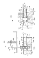
また上述した基本の実施例では、上記図1に示したように、梁材8は基本的に断面C字状のチャンネル部材を適用したが、梁材8としては必ずしもこのような断面形状に限定されるものではなく、例えば図5(a)に示すように、中空の断面I字状であって、このI字型断面下端部の両側に上向きの折り返しを持った梁材8を適用することができる。この場合、パネル固定金具81・82としては、基本的に本図5(a)に併せ示すように、先端に係止部を有する金具を一対、梁材8のI字型断面の下端部に係止させて、天井パネル1を梁材8に固定するものである。
In the basic embodiment described above, as shown in FIG. 1, the
また、本図5に示す改変例では、ターンバックル機構91による梁材8の吊持形態も変更しており、以下これについて説明する。まず、ターンバックル機構91における下部ネジボルト91Dの下端部にはナット94を設け、このナット94を、梁材8の上端部において断面C字状を成す連結部84に嵌め込み、吊持するものである。また下部ネジボルト91Dには、ナット94の上側に、断面コ字状を成すカバー95と、ワッシャ96と、ナット97とが設けられ、梁材8の連結部84にナット94を嵌め込んだ後、この連結部84をカバー95とワッシャ96とを介して、双方のナット94・97を締め付けることにより取り付けが行われる。
なお、本図5では、天井パネル1における締結手段6のエンド端からの距離、つまりエンド端からボルト締め込み位置までの距離を、基本の実施例と同一に設定したものであり(一例として48mm)、これは例えば梁材8等の既存部材が、そのまま使えるように考慮したためである。逆に言えば、締結手段6のエンド端からの距離を変更すると、梁材8等の既存部材がそのまま使えないことがあり、細部の仕様や施工方法までを大幅に変更しなければならないことがあるものである。
Further, in the modified example shown in FIG. 5, the manner in which the
In FIG. 5, the distance from the end of the fastening means 6 in the
また、上述した基本の実施例では、主にナット61として板ナットを適用し、特にメネジが形成される水平部61Hに対してほぼ90度に折り曲げた垂直部61Vを、サイド骨枠材53に固定したものである。これによりボルト63をネジ込む際にナット61の共回りをより確実に防止でき、着実に天井パネル1を梁材8に固定することができるという効果を奏するものである。
しかしながら、ナット61としては、必ずしも板ナットに限定されるものではなく、例えば図6(a)に示すように、通常の六角ナットを用いることも可能である。この場合、ナット61自体をサイド骨枠材53等の断熱材5にネジ留めすることは困難であるため、本図6(a)に併せ示すように、ナット61に平面視矩形状等の金属製プレート66を溶接しておき、主にこの金属製プレート66を例えば断熱材5に埋設する等、天井パネル1内で固定し、ボルト63のネジ込み時におけるナット61の共回りを効果的に防止することが望ましい。
Further, in the basic embodiment described above, a plate nut is mainly used as the
However, the
また上述した基本の実施例では、締結手段6として主にボルト・ナットによる螺合締結手段を採用し、このうちナット61を天井パネル1の内部に仕込む(サイド骨枠材53に固定する)とともに、もう一方のボルト63をパネル固定金具81・82の上方からネジ込み(螺合させ)、天井パネル1を梁材8に固定するものであった。
このような構成、つまり天井パネル1の内部にナット61を固定状態に仕込むことによって、天井パネル1の上部はほぼフラットとなり、オネジ部材(締結手段6)が突き出ることがないため、天井パネル1を施工現場まで搬送する場合や、製造後に倉庫等で保管する場合、あるいは施工現場等において実作業に取り掛かるまでの間の仮置き等において取り扱いが極めて行い易く、便利である。
Further, in the basic embodiment described above, screw fastening means mainly using bolts and nuts are employed as the fastening means 6, and among these, the
Since the
しかしながら、締結手段6そのものに着眼した場合には、必ずしもナット61を天井パネル1の内部に設ける必要はなく、例えば図6(b)に示すようにボルト63を、いわゆる植込みボルトのように天井パネル1内(エンド断熱材要素52)に設けることも可能である。もちろん、この場合には、本図6(b)に併せ示すように、天井パネル1の上表殻板4からボルト63のオネジ部が突出することになり、ここにパネル固定金具81(82)を差し込んだ後、その上方からナット61をネジ込んで、天井パネル1を梁材8に固定する操作となる。
However, when focusing on the fastening means 6 itself, it is not always necessary to provide the
また、締結手段そのものについてもボルト・ナット以外の手法を採用することができ、例えば図7(a)に示すように、プッシュナット形式の締結手段(これをボルト・ナット形式の締結手段6と区別したい場合に「6A」の符号を付す)を採用することができる。
このプッシュナット形式の締結手段6Aは、係止段差68Sを有したアンカー68(上記植込みボルトに相当)を天井パネル1の内部、特にここではエンド断熱材要素52に埋設しておくものであり、このアンカー68に対し、逆爪状の返し69Sが形成された差込孔付きの取付片69を強制的に嵌め込み、天井パネル1を梁材8に固定するものである。つまり、この場合には取付片69を梁材8の上方からアンカー68にほぼ真っ直ぐ嵌め込むことで、取付片69の返し69Sをアンカー68の係止段差68Sに下方から逆爪状に掛止させるものであり、これにより取付片69をアンカー68から抜けないようにするものである。
このようにプッシュナット形式の締結手段6Aでは、取付片69をアンカー68に対し直線的に嵌め込む操作のみで、天井パネル1の固定を図るものであり、この点がボルト・ナット形式の締結手段6との相違点と言える。なお、図中符号69Hは、取付片69に形成される差込孔である。
Further, a technique other than bolts and nuts can be adopted for the fastening means itself. For example, as shown in FIG. 7A, a push nut type fastening means (this is distinguished from a bolt and nut type fastening means 6). If it is desired to do so, the symbol “6A” is attached).
In this push nut type fastening means 6A, an anchor 68 (corresponding to the implanted bolt) having a locking
Thus, in the push nut type fastening means 6A, the
更にまた、ボルト・ナット形式やプッシュナット形式以外の締結手段としては、ラッチ形式の締結手段も挙げられ、このラッチ形式を前者二つの形式と区別したい場合に「6B」の符号を付すものである。
ラッチ形式の締結手段6Bは、一例として図7(b)に示すように、天井パネル1の内部、特にここではエンド断熱材要素52に突出状態に埋め込まれるアンカー71と、このアンカー71に対し閂(かんぬき)状に嵌め込まれるラッチバー72とを具えて成るものである。
ここでアンカー71は、同図7(b)に併せ示すように、ラッチバー72の挿入を可能とするラッチ挿入孔71Hを具えるものであり、このラッチ挿入孔71Hは、アンカー71を締結用開口81H(82H)に差し込んだ際に、この締結用開口81H(82H)から突出する部位に形成される。
またラッチバー72には、弾性的に潜没(没入)し得る突出部72Pが形成されることが好ましく、これは突出部72Pが無負荷状態(自然状態)では突出した状態に設定されるものの、ラッチバー72をラッチ挿入孔71Hに嵌め込んだ際には、突出部72Pがラッチ挿入孔71Hの内壁面に当接することで弾性的に没入し、その後、ラッチ挿入孔71Hを通過した時点で突出状態に復帰し、ラッチバー72の抜け止め(ラッチ挿入孔71Hからの抜け止め)作用を担うためである。ここで図中符号72Hは、ラッチバー72のラッチ挿入孔71Hへの押し込み操作等を行い易くするための操作片である。因みに、ラッチバー72は、パネル固定金具81(82)と一体(摺動自在で一体)に設けても構わないが、全く別個の部材として設けることも可能である。
Furthermore, as a fastening means other than the bolt / nut type and the push nut type, there is a latch type fastening means, and the reference numeral “6B” is given to distinguish this latch type from the former two types. .
As an example, as shown in FIG. 7B, the latch-type fastening means 6 </ b> B includes an
As shown in FIG. 7B, the
Further, the
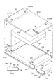
次に、図8〜図10に示す改変例について説明する。この改変例は、上記図5の形態を採った場合において、更に梁材8の下面に断熱材85を貼設した態様である。なお、この断熱材85は、上表殻板4の端部である折り返し部41Eまで掛かり、下表殻板3の上押さえ縁33を覆うように設けられる。
この改変例の場合、上押さえ縁33が、天井パネル1の内部に設けられるヒートインシュレータ65と、梁材8の下面に設けられる断熱材85とによって上下方向から挟み込まれるため、天井パネル1において上表殻板4の下面に設けていた断熱材(上記図5(a)における上押さえ材42)は必ずしも必要ではなくなる(不要となる)。
このようなことに因み、上表殻板4についても、上押さえ縁33とオーバーラップするように設ける必要がなくなる等、天井パネル1をシンプルに構成することができるものであり、以下、この改変例における各構成部材について説明する。
Next, modified examples shown in FIGS. 8 to 10 will be described. This modified example is a mode in which a
In the case of this modification, the upper pressing
For this reason, the
まず断熱材5について説明する。
断熱材5、特にエンド断熱材要素51は、図1〜図4に示した基本の実施例におけるエンド断熱材要素51よりも、サイド方向の幅寸法を長く形成しており、これは上述したように締結手段6のエンド端からの距離を基本の実施例と合わせたためである(上記のように一例として48mm)。因みに、ナット61はこのエンド断熱材要素51に埋設し、固定する構造とした。
そして、このエンド断熱材要素51の内側、つまりパネルセンター側に、エンド断熱材要素52を設けるものであり、ここでは上記のようにナット61をエンド断熱材要素51に埋設するため、エンド断熱材要素52の長さ寸法(エンド方向の寸法)は、エンド断熱材要素51と同じ長さとしている(図9(a)参照)。
因みに、エンド断熱材要素51・52のうち、いずれか一方または双方をサイド骨枠材53と同様に比較的硬い断熱性素材で形成することが好ましく、これはパネルの強度、特にエンド側の強度を増すためである。
またエンド断熱材要素52の上部には、図8に示すように係止溝52Gが形成され、この係止溝52Gのエンド側の立壁に、上押さえ縁33の自由端側に形成された折り返し部33Eを係止させるものである。また当該係止溝52Gのもう一方(パネルセンター側)の立壁に、上表殻板4における天面部41のエンド側端部に形成された折り返し部41Eを係止させるものである。
First, the
The
The end heat insulating
Incidentally, it is preferable that one or both of the end heat insulating
Further, as shown in FIG. 8, a locking
次に下表殻板3について説明する。
下表殻板3における上押さえ縁33の自由端側には、上述したように下方に向かう折り返し部33Eが形成され、この折り返し部33Eを上記係止溝52Gに係止させるものである。なお、この折り返し部33Eは、一例として図10に示すように、両サイド部では形成されないものであり、これはサイド骨枠材53との干渉を避けるためであり、本形態ではここが下表殻板3の干渉回避部34となる。
Next, the
On the free end side of the upper pressing
次に上表殻板4について説明する。
上表殻板4は、天面部41が上押さえ縁33とほぼ同じ高さの平面上に形成され、天面部41は上述したように上押さえ縁33の上方に重ならないものである。つまりボルト63が上表殻板4を貫通しないものであり、この点が上述した基本の実施例とは大きく相違する。
また、天面部41における両方のエンド端には、下向きの折り返し部41Eが形成され、この折り返し部41Eが、上述したようにエンド断熱材要素52の上面に形成された係止溝52G(パネルセンター側の傾斜壁面)に係止するものである。因みに、この折り返し部41Eも、一例として図10に示すように、両サイド部では形成されないものであり、これはサイド骨枠材53との干渉を避けるためである(この逃げ部分を上表殻板4の干渉回避部43とする)。
Next, the
The upper
In addition, downward folded
なお、本改変例における断熱材85は、梁材8の下面に設けられるが、この断熱材85は、上述したように上表殻板4におけるエンド側の折り返し部41Eまで掛かるように設けられることが望ましい。これは上押さえ縁33における折り返し部33Eが露出すると(断熱材85によって覆われないと)、当該折り返し部33Eが外気(室外空気)に触れ、熱絶縁が確保できないことが懸念されるためである。
因みに、天井パネル1に断熱性が要求されない場合には、上記断熱材5と同様に、当該断熱材85も省略することができる。
In addition, although the
Incidentally, when the
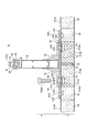
また、上述した基本の実施例では、ボルト63やナット61を上方から下方、つまり垂直方向に締め込んで(締結して)、天井パネル1を梁材8に固定する形態を主に説明したが、締結手段6の締結方向(取付方向)は必ずしもこれに限定されるものではなく、特に上記図8〜図10の改変例においては、例えば締結手段6の締結方向をほぼ水平方向とすることが可能であり、以下、この形態について説明する。
これには、例えば図11に示すように、まず下表殻板3におけるエンド端縁を上表殻板4の天面部41よりも幾分上方に突出させ、ここに妻面部32に対向するほぼ垂直な立ち上がり面を形成しておく。そして、この立ち上がり面を利用してパネル固定金具81(82)との接合を図るものであり、ナット61は当該立ち上がり面からほぼヒートインシュレータ65の厚み寸法分、奥まった位置に正立状態で埋設する。このようにすれば、上記ナット61に対し、ほぼ水平方向からボルト63を締め込むことにより、天井パネル1を梁材8に固定することができるものである。
Further, in the basic embodiment described above, the configuration in which the
For example, as shown in FIG. 11, first, the end edge of the lower
なお、上記図11において、妻面部32に対向する立ち上がり面でパネル固定金具81(82)との固定を図るようにしたのは、妻面部32には通常、隣り合う他の天井パネル1の妻面部32が位置するためである(図8参照)。
因みに、上記のように締結方向がほぼ水平の場合(垂直でない場合)には、特に直線的に取付片69(図7(a)参照)を嵌め込むプッシュナット形式でも極めて高い締結力が得られ、一旦、梁材8との固定を図った天井パネル1は、ほぼ脱落(落下)しないものと考えられる。これは、締結方向が水平方向であれば、アンカー68に取付片69を嵌め込む取付方向(水平)と、天井パネル1の落下方向(垂直)とがほぼ直交するためである。言い換えれば、例えばプッシュナット形式におけるアンカー68(図11のボルト63に相当)が剪断方向に破断すれば、梁材8に固定した天井パネル1が脱落(落下)するが、このような事態はまず生じないためである。
In FIG. 11, the panel fixing bracket 81 (82) is fixed on the rising surface facing the
Incidentally, when the fastening direction is substantially horizontal (not vertical) as described above, an extremely high fastening force can be obtained even with a push nut type that fits the mounting piece 69 (see FIG. 7A) linearly. The
S 支持構造(天井パネルの支持構造)
1 天井パネル
2 吊持部材
1 天井パネル
3 下表殻板
4 上表殻板
5 断熱材(断熱集合体)
6 締結手段(ボルト・ナット形式の締結手段)
3 下表殻板
31 展開面部
31S 折り返し部
32 妻面部
33 上押さえ縁
33H 締結用開口
33E 折り返し部
34 干渉回避部
4 上表殻板
41 天面部
41E 折り返し部(エンド端)
41S 折り返し部(サイド端)
41H 締結用開口
42 上押さえ材(断熱材)
42H 締結用開口
43 干渉回避部
5 断熱材(断熱集合体)
51 エンド断熱材要素(長)
52 エンド断熱材要素(短)
52G 係止溝
53 サイド骨枠材
53T メスザネ(雌実)
53t オスザネ(雄実)
54 センター断熱材要素
6 締結手段(ボルト・ナット形式の締結手段)
61 ナット
61H 水平部
61V 垂直部
62 ナット受け材
62E 底付き防止部
63 ボルト
64 ワッシャ(座金)
65 ヒートインシュレータ
66 金属製プレート
6A プッシュナット形式の締結手段
68 アンカー
68S 係止段差
69 取付片
69S 返し
69H 差込孔
6B ラッチ形式の締結手段
71 アンカー
71H ラッチ挿入孔
72 ラッチバー
72P 突出部
72H 操作片
2 吊持部材
8 梁材(補強梁)
9 連結部材
8 梁材(補強梁)
81 パネル固定金具(クランク状)
81H 締結用開口
82 パネル固定金具(偏平状)
82H 締結用開口
83 クサビ
84 連結部
85 断熱材
9 連結部材
91 ターンバックル機構
91U 上部ネジボルト
91D 下部ネジボルト
91T ターンバックル
92 吊り金具
93 吊り金具
94 ナット
95 カバー
96 ワッシャ
97 ナット
B 建屋梁
M アングルピース
F 嵌込縁
J 妻面用接続片
PJ パネル嵌合材
R 嵌合材受入部
S Support structure (support structure for ceiling panel)
1
1
6 Fastening means (bolt / nut type fastening means)
3 Lower
4
41S Folding part (side edge)
41H Opening for fastening 42 Upper presser (heat insulating material)
42H Fastening opening 43 Interference avoidance part
5 Insulation (insulation aggregate)
51 End insulation element (long)
52 End insulation element (short)
53t Osane
54 Center insulation element
6 Fastening means (bolt / nut type fastening means)
61
65
6A Push nut type fastening means 68
6B Latch
2
9 Connecting members
8 Beam material (Reinforcement beam)
81 Panel fixing bracket (Crank shape)
81H Fastening opening 82 Panel fixing bracket (flat)
82H Opening for fastening 83
9 Connecting
B Building beam M Angle piece F Fitting edge J Connection piece for end face PJ Panel fitting material R Fitting material receiving part
Claims (10)
この天井パネルは、平面形状が矩形状を呈する上下の表殻板を具えて成るものであり、
このうち下表殻板は、少なくとも対向する二縁辺が、室内天井面に相当する展開面部に対し上方に折り返し状に形成され、この折り返し部分において、前記吊持部材との取り付けを図るようにしたことを特徴とする天井パネル。
In the ceiling panel supported near the ceiling by a suspension member provided in a suspended state from the structural material of the building,
This ceiling panel is composed of upper and lower outer shell plates having a rectangular planar shape,
Of these, the lower shell plate is formed so that at least two opposing edges are folded upward with respect to the development surface corresponding to the indoor ceiling surface, and the folded member is attached to the suspension member. A ceiling panel characterized by that.
この上押さえ縁と吊持部材とには、これらの固定を図るための締結用開口が各々対応した位置に形成され、
また天井パネルの内部には、締結手段の一方が設けられるものであり、
天井パネルを吊持部材に固定するにあたっては、前記締結手段により、上押さえ縁と吊持部材とに形成された締結用開口を通して下表殻板を吊持部材に固定するようにしたことを特徴とする請求項1記載の天井パネル。
The site where the lower shell plate is attached to the suspension member is an upper holding edge formed by folding back in a substantially opposite state with respect to the development surface portion,
The upper pressing edge and the suspension member are formed with fastening openings for fixing them at corresponding positions,
One of the fastening means is provided inside the ceiling panel,
When fixing the ceiling panel to the suspension member, the lower shell plate is fixed to the suspension member through the fastening opening formed in the upper pressing edge and the suspension member by the fastening means. The ceiling panel according to claim 1.
In forming the upper pressing edge substantially opposite to the development surface portion of the lower shell plate, the upper surface edge is further extended from the development surface portion to the development surface portion with respect to the wife surface portion formed so as to rise substantially at a right angle. The ceiling panel according to claim 2, wherein an upper holding edge is formed by bending inwardly at a substantially right angle so as to be along.
In attaching the ceiling panel, the fastening means penetrates the upper pressing edge of the lower surface shell plate, and the upper surface shell plate also penetrates to fix the lower surface shell plate to the suspension member. The ceiling panel according to claim 2 or 3, characterized in that
The ceiling panel according to claim 2, 3 or 4, wherein when one of the fastening means is provided inside the ceiling panel, a heat insulator is provided so that the fastening means and the outer shell plate are not in direct contact with each other. .
The ceiling panel according to claim 5, wherein a portion of the upper pressing edge that receives fastening by fastening means is further provided with a heat insulating member on the upper side of the upper pressing edge.
The ceiling panel according to claim 2, 3, 4, 5, or 6, wherein the upper pressing edge of the lower shell plate and the suspension member are screwed to each other by applying a bolt and a nut. .
The ceiling panel according to claim 7, wherein the fastening means provided in the ceiling panel is a nut.
The nut is a plate nut having a horizontal part in which a female screw is formed and a vertical part that is bent at a substantially right angle to the horizontal part, and the vertical part is fixed inside the ceiling panel. The ceiling panel according to claim 8, wherein
このうち一方の骨枠材には、隣り合うパネル同士を接続するオスザネが形成され、もう一方の骨枠材には、このオスザネに嵌まるメスザネが形成されることを特徴とする請求項3、4、5、6、7、8または9記載の天井パネル。 The pair of other surfaces other than the pair of wife face portions in which the upper pressing edge is continuously formed is provided with a pair of bone frame members in a direction substantially orthogonal to the wife face portion,
One of the bone frame members is formed with a male zannet that connects adjacent panels, and the other bone frame member is formed with a female zannet that fits into the male frame. The ceiling panel according to 4, 5, 6, 7, 8 or 9.
Priority Applications (1)
| Application Number | Priority Date | Filing Date | Title |
|---|---|---|---|
| JP2012239495A JP2014088711A (en) | 2012-10-30 | 2012-10-30 | Ceiling panel |
Applications Claiming Priority (1)
| Application Number | Priority Date | Filing Date | Title |
|---|---|---|---|
| JP2012239495A JP2014088711A (en) | 2012-10-30 | 2012-10-30 | Ceiling panel |
Publications (1)
| Publication Number | Publication Date |
|---|---|
| JP2014088711A true JP2014088711A (en) | 2014-05-15 |
Family
ID=50790810
Family Applications (1)
| Application Number | Title | Priority Date | Filing Date |
|---|---|---|---|
| JP2012239495A Pending JP2014088711A (en) | 2012-10-30 | 2012-10-30 | Ceiling panel |
Country Status (1)
| Country | Link |
|---|---|
| JP (1) | JP2014088711A (en) |
Cited By (5)
| Publication number | Priority date | Publication date | Assignee | Title |
|---|---|---|---|---|
| JP2016196762A (en) * | 2015-04-03 | 2016-11-24 | 帝人株式会社 | Structure and method for fixing ceiling material |
| CN109403639A (en) * | 2018-09-27 | 2019-03-01 | 上海市建筑装饰工程集团有限公司 | Big area roof truss stress check calculation layer installation method |
| JP2020190120A (en) * | 2019-05-22 | 2020-11-26 | 株式会社ソーゴ | Metal fitting for ceiling joist |
| KR20210130586A (en) * | 2020-04-22 | 2021-11-01 | 정민시 | Means of mounting the main carrier of the ceiling light steel structure |
| WO2025193916A1 (en) * | 2024-03-14 | 2025-09-18 | Xo Structure Corporation | Anti-thermal bridging suspended ceiling system |
Citations (2)
| Publication number | Priority date | Publication date | Assignee | Title |
|---|---|---|---|---|
| JPS61168212U (en) * | 1985-04-05 | 1986-10-18 | ||
| JPH11217919A (en) * | 1998-01-30 | 1999-08-10 | Mdi:Kk | Building surface part fixing method and finishing panel |
-
2012
- 2012-10-30 JP JP2012239495A patent/JP2014088711A/en active Pending
Patent Citations (2)
| Publication number | Priority date | Publication date | Assignee | Title |
|---|---|---|---|---|
| JPS61168212U (en) * | 1985-04-05 | 1986-10-18 | ||
| JPH11217919A (en) * | 1998-01-30 | 1999-08-10 | Mdi:Kk | Building surface part fixing method and finishing panel |
Cited By (8)
| Publication number | Priority date | Publication date | Assignee | Title |
|---|---|---|---|---|
| JP2016196762A (en) * | 2015-04-03 | 2016-11-24 | 帝人株式会社 | Structure and method for fixing ceiling material |
| CN109403639A (en) * | 2018-09-27 | 2019-03-01 | 上海市建筑装饰工程集团有限公司 | Big area roof truss stress check calculation layer installation method |
| CN109403639B (en) * | 2018-09-27 | 2021-04-06 | 上海市建筑装饰工程集团有限公司 | Installation method of stress transfer layer of large area roof truss |
| JP2020190120A (en) * | 2019-05-22 | 2020-11-26 | 株式会社ソーゴ | Metal fitting for ceiling joist |
| KR20210130586A (en) * | 2020-04-22 | 2021-11-01 | 정민시 | Means of mounting the main carrier of the ceiling light steel structure |
| US11428000B2 (en) | 2020-04-22 | 2022-08-30 | Min Si JUNG | Means of mounting a main carrier of a ceiling lightweight steel structure |
| KR102470244B1 (en) * | 2020-04-22 | 2022-11-23 | 정민시 | Means of mounting the main carrier of the ceiling light steel structure |
| WO2025193916A1 (en) * | 2024-03-14 | 2025-09-18 | Xo Structure Corporation | Anti-thermal bridging suspended ceiling system |
Similar Documents
| Publication | Publication Date | Title |
|---|---|---|
| EP3080361B1 (en) | Drywall joist hanger connection | |
| JP2014088711A (en) | Ceiling panel | |
| CN103635641B (en) | For two juxtaposed plates being installed to structure thus the assembly of permission thermal expansion and contraction | |
| US10309100B2 (en) | Mullion cover hanger and curtain wall insulation system incorporating the same | |
| AU2013307299B2 (en) | Apparatus for securing insulation panels to a supporting structure and ceiling support assembly incorporating the same | |
| SK533188A3 (en) | Wall panel | |
| KR101663986B1 (en) | Bracket for fix furniture to the wall | |
| KR101464921B1 (en) | A fixing apparatus of insulation material and constructing method thereof | |
| JP2017115308A (en) | Crimp metal fitting for roof | |
| JP2010144402A (en) | Installing structure of panel | |
| EP2706165A1 (en) | Method for installing dry cladding on a flat structural surface, insulation panel for use in such a method and method for producing such an insulation panel | |
| KR200489521Y1 (en) | Wall Finishiing Assembly | |
| JP2010090636A (en) | Flat panel mounting tool and flat panel mounting structure | |
| KR20060026562A (en) | Ceiling panel and installation member and ceiling panel construction method | |
| JP6438185B2 (en) | Thermal insulation panel | |
| JP5706661B2 (en) | Fireproof panel | |
| JP6408206B2 (en) | Thermal insulation panel | |
| KR20230122071A (en) | curtain wall insulation system | |
| CN102943526A (en) | Building combined pendant, building structure and construction method | |
| CN112144677B (en) | Edge folding structure of module box house and construction method thereof | |
| JP2008057278A (en) | Suspending tool installing structure | |
| JP5824203B2 (en) | Insulation panel construction structure | |
| JPH0875345A (en) | Assembling type cooling refrigerator | |
| JPH04194263A (en) | Exterior wall panels in buildings | |
| JP2000237337A (en) | Mounting structure and mounting method of smokeproof hanging wall |
Legal Events
| Date | Code | Title | Description |
|---|---|---|---|
| A621 | Written request for application examination |
Free format text: JAPANESE INTERMEDIATE CODE: A621 Effective date: 20151007 |
|
| A977 | Report on retrieval |
Free format text: JAPANESE INTERMEDIATE CODE: A971007 Effective date: 20160817 |
|
| A131 | Notification of reasons for refusal |
Free format text: JAPANESE INTERMEDIATE CODE: A131 Effective date: 20160830 |
|
| A02 | Decision of refusal |
Free format text: JAPANESE INTERMEDIATE CODE: A02 Effective date: 20170307 |