JP2014085366A - Ceiling mounting type sensor - Google Patents
Ceiling mounting type sensor Download PDFInfo
- Publication number
- JP2014085366A JP2014085366A JP2012231477A JP2012231477A JP2014085366A JP 2014085366 A JP2014085366 A JP 2014085366A JP 2012231477 A JP2012231477 A JP 2012231477A JP 2012231477 A JP2012231477 A JP 2012231477A JP 2014085366 A JP2014085366 A JP 2014085366A
- Authority
- JP
- Japan
- Prior art keywords
- ceiling
- cover
- inner cover
- opening
- waterproof wall
- Prior art date
- Legal status (The legal status is an assumption and is not a legal conclusion. Google has not performed a legal analysis and makes no representation as to the accuracy of the status listed.)
- Granted
Links
- XLYOFNOQVPJJNP-UHFFFAOYSA-N water Substances O XLYOFNOQVPJJNP-UHFFFAOYSA-N 0.000 claims abstract description 52
- 239000000758 substrate Substances 0.000 claims abstract description 28
- 238000012544 monitoring process Methods 0.000 claims description 24
- 238000003780 insertion Methods 0.000 claims description 12
- 230000037431 insertion Effects 0.000 claims description 12
- 238000007599 discharging Methods 0.000 claims description 3
- 230000005855 radiation Effects 0.000 claims description 2
- 230000017525 heat dissipation Effects 0.000 description 4
- 230000002093 peripheral effect Effects 0.000 description 3
- 238000009434 installation Methods 0.000 description 2
- 230000000630 rising effect Effects 0.000 description 2
- 239000003990 capacitor Substances 0.000 description 1
- 238000001514 detection method Methods 0.000 description 1
- 230000005489 elastic deformation Effects 0.000 description 1
- 230000012447 hatching Effects 0.000 description 1
- 238000012856 packing Methods 0.000 description 1
- 230000002265 prevention Effects 0.000 description 1
- 238000007789 sealing Methods 0.000 description 1
- 239000004065 semiconductor Substances 0.000 description 1
- 238000009423 ventilation Methods 0.000 description 1
- 238000004078 waterproofing Methods 0.000 description 1
Images


Classifications
-
- G—PHYSICS
- G03—PHOTOGRAPHY; CINEMATOGRAPHY; ANALOGOUS TECHNIQUES USING WAVES OTHER THAN OPTICAL WAVES; ELECTROGRAPHY; HOLOGRAPHY
- G03B—APPARATUS OR ARRANGEMENTS FOR TAKING PHOTOGRAPHS OR FOR PROJECTING OR VIEWING THEM; APPARATUS OR ARRANGEMENTS EMPLOYING ANALOGOUS TECHNIQUES USING WAVES OTHER THAN OPTICAL WAVES; ACCESSORIES THEREFOR
- G03B17/00—Details of cameras or camera bodies; Accessories therefor
- G03B17/02—Bodies
- G03B17/08—Waterproof bodies or housings
-
- G—PHYSICS
- G08—SIGNALLING
- G08B—SIGNALLING OR CALLING SYSTEMS; ORDER TELEGRAPHS; ALARM SYSTEMS
- G08B13/00—Burglar, theft or intruder alarms
- G08B13/18—Actuation by interference with heat, light, or radiation of shorter wavelength; Actuation by intruding sources of heat, light, or radiation of shorter wavelength
- G08B13/189—Actuation by interference with heat, light, or radiation of shorter wavelength; Actuation by intruding sources of heat, light, or radiation of shorter wavelength using passive radiation detection systems
- G08B13/194—Actuation by interference with heat, light, or radiation of shorter wavelength; Actuation by intruding sources of heat, light, or radiation of shorter wavelength using passive radiation detection systems using image scanning and comparing systems
- G08B13/196—Actuation by interference with heat, light, or radiation of shorter wavelength; Actuation by intruding sources of heat, light, or radiation of shorter wavelength using passive radiation detection systems using image scanning and comparing systems using television cameras
- G08B13/19617—Surveillance camera constructional details
- G08B13/19619—Details of casing
Abstract
Description
本発明は、天井に設置される監視センサを備えた天井取付型センサに関する。 The present invention relates to a ceiling-mounted sensor provided with a monitoring sensor installed on a ceiling.
防犯や人の混雑状況の把握などを目的として建物内に設置されている監視センサとして例えば監視カメラがある。
監視カメラは、周囲を広く見渡せる場所に設置されることが望まれるため、天井に設置される場合が多い。天井に設定される監視カメラは、カメラの存在を意識させないようにするために、また、設置付近の景観を損なわせないようにするために、光を透過する半球体状のドームでカメラ部を覆うようにしたドーム型カメラが主流となっている(例えば特許文献1参照)。
For example, there is a monitoring camera as a monitoring sensor installed in a building for the purpose of crime prevention or grasping the congestion situation of people.
Surveillance cameras are often installed on the ceiling because it is desired to be installed in a place with a wide view of the surroundings. The surveillance camera set on the ceiling has a hemispherical dome that transmits light in order to prevent the camera from being aware of the presence of the camera and to prevent damage to the scenery near the installation. Covered dome cameras are the mainstream (see, for example, Patent Document 1).
特許文献1に開示されているような天井取付型の監視カメラは、外部からドーム内への水の浸入を防ぐために、ドームの部分とカメラが固定されるベース部分との間をパッキンによりシールしている。しかしながら、ベース部分の天井との対向部には、内部に配置される基板に接続するための配線を挿通させる孔が開口されており、この孔から水が浸入してしまうと、電子部品に水滴が落下してしまい、電子部品が損傷してしまう問題がある。特に、水滴が落ちてくる場所に監視カメラが設置される場合には、天井に水滴が付着しやすいので、ドーム内に水が浸入する可能性が高くなる。そこで、完全防水構造を実現しようとすると密閉のため機器の厚みが増え、重量が重くなることとなる。また、密閉構造のため放熱性の問題も発生する。さらに、天井に設置する条件下では薄型(軽量)であることが望まれ、屋内の設置であれば防水ではなく防滴構造で十分である。
In order to prevent water from entering the dome from the outside, the ceiling-mounted surveillance camera as disclosed in
本発明は、上記事情に鑑みてなされ、内部の電子部品等への水の接触を阻止することができる防滴構造に優れた天井取付型センサを提供することを目的とする。 The present invention has been made in view of the above circumstances, and an object thereof is to provide a ceiling-mounted sensor excellent in a drip-proof structure capable of preventing contact of water with an internal electronic component or the like.
本発明の天井取付型センサは、
電子部品が取り付けられた基板と、
天井に設置される基板が装着されたベース部と、
基板に接続される監視センサと、
監視センサの一部が露出する内側開口部を有し、基板及び監視センサを覆った状態でベース部に取り付けられるインナーカバーと、
インナーカバーの内側開口部が露出する外側開口部を有し、インナーカバー及びベース部を覆うアウターカバーとを備え、
前記ベース部は、基板に取り付けられた電子部品及びインナーカバーの周囲に設けられる防水壁部と、防水壁部の外側に形成される複数の貫通孔とを有することを特徴とする。
The ceiling-mounted sensor of the present invention is
A board with electronic components attached,
A base part mounted with a substrate installed on the ceiling;
A monitoring sensor connected to the substrate;
An inner cover that has an inner opening from which a part of the monitoring sensor is exposed, and is attached to the base in a state of covering the substrate and the monitoring sensor;
An outer opening that exposes the inner opening of the inner cover, and an outer cover that covers the inner cover and the base,
The base portion includes a waterproof wall portion provided around an electronic component and an inner cover attached to the substrate, and a plurality of through holes formed outside the waterproof wall portion.
このような構成によれば、ベース部の天井との対向面に付着した水滴は、ベース部に設けた貫通孔またはベース部の外周縁からアウターカバー内に浸入しても、防水壁部の外側で落下する。そして、基板に取り付けられた電子部品、監視センサ及びインナーカバーの周囲には防水壁部が設けられているので、この防水壁部により電子部品、監視センサ及びインナーカバーを取り付けるためのネジなどへの水の接触が阻止される。
なお、監視センサとしては、動画が撮影可能なカメラや赤外線カメラなどにより構成することができる。
According to such a configuration, even if water droplets adhering to the surface of the base portion facing the ceiling enter the outer cover from the through hole provided in the base portion or the outer peripheral edge of the base portion, the outside of the waterproof wall portion Fall at. Since a waterproof wall is provided around the electronic component, the monitoring sensor, and the inner cover attached to the substrate, the waterproof wall allows the electronic component, the monitoring sensor, and the screw for attaching the inner cover to the screw, etc. Water contact is prevented.
Note that the monitoring sensor can be configured by a camera capable of shooting a moving image, an infrared camera, or the like.
さらに、本発明の天井取付型センサは、
基板には、外部からのケーブルが接続されるコネクタが取り付けられ、
インナーカバーは、コネクタの接続ポートが露出するコネクタ開口部を有し、
ベース部は、防水壁部の外側であって、コネクタの近傍に前記貫通孔となるケーブルが挿通されるケーブル挿通孔を有し、
コネクタの接合口は、斜め下方に防水壁部に向けて開口され、
ベース部のケーブル挿通孔に挿通されたケーブルは、アウターカバーの底部内面に接触可能に下方に向けて湾曲させてコネクタに接続させる構成とすることが好ましい。
Furthermore, the ceiling-mounted sensor of the present invention is
A connector to which an external cable is connected is attached to the board,
The inner cover has a connector opening where the connection port of the connector is exposed,
The base part is outside the waterproof wall part, and has a cable insertion hole through which the cable serving as the through hole is inserted in the vicinity of the connector.
The connector joint is opened obliquely downward toward the waterproof wall,
The cable inserted into the cable insertion hole of the base portion is preferably configured to be bent downward so as to be in contact with the inner surface of the bottom portion of the outer cover and connected to the connector.
このような構成によれば、コネクタに接続されるケーブルに水滴が付着しても、ケーブルは、アウターカバー内において、下方に向けて湾曲した後、コネクタに接続されるので、ケーブルに付着した水滴は、コネクタに向かって上昇することなくアウターカバーの底部内面に落下するので、コネクタの接続ポートがインナーカバーから露出していても、水による損傷を阻止できる。 According to such a configuration, even if water drops adhere to the cable connected to the connector, the cable is bent downward in the outer cover and then connected to the connector. Falls to the inner surface of the bottom of the outer cover without rising toward the connector, so that damage due to water can be prevented even if the connection port of the connector is exposed from the inner cover.
また、インナーカバーは、下面にのみ複数の放熱用通気孔が形成されるように構成することが好ましい。
このように、インナーカバーに放熱用通気孔が形成されることで、放熱用通気孔から水が上昇して内部に浸入することはないので、放熱用通気孔が形成されていてもインナーカバー内への水の浸入を阻止できる。
The inner cover is preferably configured such that a plurality of heat radiating vents are formed only on the lower surface.
In this way, since the heat dissipation vent is formed in the inner cover, water does not rise from the heat dissipation vent and enter the inside, so even if the heat dissipation vent is formed, Can prevent water from entering
また、インナーカバーは、内側開口部の周囲に下方に向けて突出する環状突起が形成され、環状突起がアウターカバーの外側開口部に挿入されるように構成することが好ましい。
このように、内側開口部の周囲に形成された環状突起により、内側開口部から水滴が内部に浸入することを阻止することができる。
Further, it is preferable that the inner cover is configured such that an annular protrusion protruding downward is formed around the inner opening, and the annular protrusion is inserted into the outer opening of the outer cover.
As described above, the annular protrusion formed around the inner opening can prevent water droplets from entering the inside from the inner opening.
さらに、ベース部の防水壁部と、防水壁部に対向するアウターカバーの側壁部との間に水浸入通路が形成されるように構成することが好ましい。
このように水浸入通路を形成することで、ベース部の上面部に付着した水滴は水浸入通路を構成するアウターカバーの側壁部または防水壁部の外面を伝わって基板に接触させることなくアウターカバーの底部内面に落下させることができる。
Furthermore, it is preferable that the water intrusion passage is formed between the waterproof wall portion of the base portion and the side wall portion of the outer cover facing the waterproof wall portion.
By forming the water intrusion passage in this way, the water droplets adhering to the upper surface portion of the base portion travel along the side wall portion of the outer cover or the outer surface of the waterproof wall portion constituting the water intrusion passage without contacting the substrate. Can be dropped on the inner surface of the bottom.
また、アウターカバーの底部内面は、外側開口部に向けて下方に傾斜する傾斜面を備え、アウターカバーの外側開口部とインナーカバーの内側開口部との間に、水を排出する水排出通路を形成するように構成することが好ましい。
このように、アウターカバーの底部内面に落下した水滴は、傾斜面に沿って外側開口部に向かって流れて、水排出通路から外部に排出される。
The inner surface of the bottom of the outer cover has an inclined surface that is inclined downward toward the outer opening, and a water discharge passage for discharging water is provided between the outer opening of the outer cover and the inner opening of the inner cover. It is preferable to form so as to form.
As described above, the water droplets falling on the inner surface of the bottom of the outer cover flow toward the outer opening along the inclined surface, and are discharged to the outside through the water discharge passage.
本発明の天井取付型センサによれば、ベース部の上面部の天井側に水滴が付着しても、付着した水滴は、ベース部に設けた貫通孔及びベース部の外周縁から防水壁部の外側に落下し、防水壁部により電子部品及びインナーカバー等への水滴の接触は阻止される。その結果、湿度の高い場所に監視センサを設置しても、基板に取り付けた監視センサや各電子部品、及び、インナーカバーをベースに取り付けるためのネジなどが水滴に接触して損傷することを阻止することができる。 According to the ceiling-mounted sensor of the present invention, even if water droplets adhere to the ceiling side of the upper surface portion of the base portion, the adhered water droplets are formed on the waterproof wall portion from the through hole provided in the base portion and the outer peripheral edge of the base portion. It falls to the outside, and the waterproof wall prevents water droplets from coming into contact with electronic components and the inner cover. As a result, even if a monitoring sensor is installed in a place with high humidity, the monitoring sensor attached to the board, each electronic component, and the screws used to attach the inner cover to the base are prevented from being damaged by contact with water droplets. can do.
以下に、本発明の天井取付型センサとしての天井取付型カメラに係る実施形態について添付図面を参照しながら説明する。
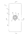
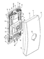
図1から図6に示す天井取付型カメラ1は、半導体、コンデンサなどの電子部品が取り付けられた基板2と(図5及び図6に示す)、基板2が装着された状態で天井に取り付けられる長方形状のベース部3と、基板2を覆うインナーカバー4と、ベース部3及びインナーカバー4を覆うアウターカバー5とを備える。
Hereinafter, an embodiment according to a ceiling-mounted camera as a ceiling-mounted sensor of the present invention will be described with reference to the accompanying drawings.
A ceiling-mounted
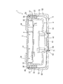
基板2には、監視センサである監視カメラ61が、フラットケーブルを介して基板2に接続されている。また、基板2には、外部からのケーブル62が接続される端子台63、USBメモリが接続されるUSBコネクタ64、各種スイッチ65が取り付けられている。監視カメラ61は、図5及び図6に示すように、長方形の基板2の中央部に対向するようにインナーカバー4の底部内面に固定されている。また、端子台63は基板2の長手方向一端部に固定され、USBコネクタ64は基板2の長手方向他端部に固定され、スイッチ65は、USBコネクタ64に隣接して基板2に固定されている。
A
端子台63には、ケーブル62の複数の配線を分岐させて接続する複数の接続ポート63aが設けられており、これら接続ポート63aは、図5に示すように、ベース部3を天井に取り付けた状態において斜め下方外側に向けて開口されている。USBコネクタ64には、USBメモリが接続されるUSB接続ポート64aが水平方向に開口するように形成されている。
The
ベース部3は、長方形の板状に形成された上面部31と、上面部31の外周囲に、上面部31が天井に固定された状態において下方に向けて突設される縁部32とを備える。上面部31の下面側に基板2がインナーカバー4と共にネジ66締めにより取り付けられる。ベース部3は、基板2の面積よりも大きい面積を有している。
The
インナーカバー4は、基板2全体を覆った状態でベース部3にネジ66締めして取り付けられる。インナーカバー4には、監視カメラ61の一部であるレンズ部分が露出する内側開口部41と、端子台63の接続ポート63aを露出させる端子台開口部42と、USBコネクタ64のUSB接続ポート64aが突出されるUSB開口部43と、各種スイッチ65を露出させるスイッチ開口部44とを有する。
The inner cover 4 is attached to the
さらに、インナーカバー4は、図3及び図4に示すように、ベース部3が天井に固定された状態において下面となる部分にのみ複数の放熱用通気孔45が形成されている。放熱用通気孔45がインナーカバー4の下面にのみ形成されることで、放熱用通気孔45から水が上昇してインナーカバー4の内部に浸入することを阻止する。
Further, as shown in FIGS. 3 and 4, the inner cover 4 is formed with a plurality of heat-dissipating vent holes 45 only in a portion that becomes the lower surface when the
また、インナーカバー4は、内側開口部41の周囲に下方に向けて突出する環状突起46を形成しており、環状突起46がアウターカバー5の外側開口部53に挿入されるようになっている。内側開口部41の周囲に環状突起46を形成することによって、内側開口部41から水滴がインナーカバー4の内部に浸入することを阻止する。
Further, the inner cover 4 is formed with an
アウターカバー5は、平面視において長方形状に形成され、底部内面51が長手方向に湾曲し、この湾曲した底部内面51の周縁に側壁部52が形成されている。アウターカバー5は、インナーカバー4及びベース部3の全てを覆うように形成され、図2に示すように、ベース部3の外周縁の縁部32に沿って側壁部52をベース部3に嵌め合わすように構成されている。さらに、アウターカバー5には、インナーカバー4の内側開口部41の周囲に形成した環状突起46が挿入される外側開口部53を有している。この外側開口部53から監視カメラ61のレンズが露出された状態になる。さらに、アウターカバー5の短辺の側壁部52の内面側には、ベース部3に形成するフック36が掛けられる軸状のフック係止部54が形成されている。
The
アウターカバー5の湾曲した底部内面51は、外側開口部53に向けて下方に傾斜するように長手方向にのみ傾斜するように形成される。そして、アウターカバー5の外側開口部53とインナーカバー4の内側開口部41に形成された環状突起46との間に、水を排出する水排出通路71が形成される(図1に示すクロスハッチングの部分)。ベース部3とアウターカバー5との隙間や、ベース部3に形成した天井固定用ビス孔34及びケーブル挿通孔35から水滴が浸入してアウターカバー5の底部内面に落下すると、水滴は傾斜面に沿って外側開口部53に向かって流れて、水排出通路71から外部に排出される。
The curved bottom
さらにベース部3には、図3及び図4に示すように、基板2に取り付けられたスイッチ65などの電子部品、端子台63の接続ポート63a、USBコネクタ64のUSB接続ポート64a及びインナーカバー4の周囲を囲むように防水壁部33が下方に向けて突設されている。防水壁部33は、ベース部3における縁部32の長辺部分に延設される部分と、縁部32の短辺部分よりも内側に上面部31の下面側から下方に向けて突設され、長辺縁部32に延設された防水壁部33に連続する部分とにより構成されている(図3及び図4に示すクロスハッチングの部分)。防水壁部33により、インナーカバー4から露出する端子台63の接続ポート63a、スイッチ65、USB接続ポート64a、そして、インナーカバー4をベース部3に固定するためのネジ66などに向かって水滴が流れていくのが阻止される。
Further, as shown in FIGS. 3 and 4, the
さらに、ベース部3は、図4に示すように、USBコネクタ64の近傍の防水壁部33の外側に2つの天井固定用ビス孔34(本発明の貫通孔)が形成されると共に、端子台63の近傍の防水壁部33の外側にケーブル62が挿通される2つのケーブル挿通孔35(本発明の貫通孔)が形成され、これらケーブル挿通孔35の間に天井固定用ビス孔34(本発明の貫通孔)が形成されている。ベース部3のケーブル挿通孔35に挿通されたケーブル62は、図5に示すように、アウターカバー5の底部内面51に接触させた状態で下方に向けて湾曲させて端子台63の接続ポート63aに接続させるようになっている。
Further, as shown in FIG. 4, the
さらに、ベース部3には、アウターカバー5に形成されるフック係止部54に掛けられる1対のフック36がケーブル挿通孔35の近くに外側に向かって湾曲するように形成されている。さらに、アウターカバー5における長辺の側壁部52内面の中央部と、ベース部3における長辺の縁部32外面の中央部とには、アウターカバー5の側壁部52の弾性変形により係止するストッパー部55,38が形成されている。ベース部3のフック36にアウターカバー5のフック係止部54を掛けながら、ベース部3の縁部32にアウターカバー5の側壁部52が沿うようにアウターカバー5をベース部3に向けて押込むと、ストッパー部55,38同士が係合してアウターカバー5がベース部3に支持された状態となる。
Further, the
さらに、ベース部3における長辺縁部32及びこの長辺縁部32に連続して形成される防水壁部33には内方に凹んだ凹部37が形成されており、この凹部37に対向するアウターカバー5の側壁部52との間に、水浸入通路72が形成される。水浸入通路72が形成されているので、ベース部3の上面部31に付着した水滴は水浸入通路72を構成するアウターカバー5の側壁部52またはベース部3の防水壁部33及び長辺縁部32の外面を伝わって基板2及びインナーカバー4に接触することなくアウターカバー5の底部内面51に落下する。
Furthermore, a
本実施形態の天井取付型カメラ1によれば、ベース部3に防水壁部33及び貫通孔となる天井固定用ビス孔34及びケーブル挿通孔35を設けているので、ベース部3の天井との対向面である上面部31に付着した水滴は、ベース部3に設けた天井固定用ビス孔34、ケーブル挿通孔35または水浸入通路72からアウターカバー5内に浸入しても、防水壁部33の外側でアウターカバー5の底部内面51に落下する。そして、端子台63、USBコネクタ64、各種スイッチ65及びインナーカバー4の周囲には防水壁部33が設けられているので、この防水壁部33により端子台63、USBコネクタ64、各種スイッチ65及びインナーカバー4を取り付けるためのネジ66などへの水の接触が阻止される。
According to the ceiling-mounted
さらに、端子台63に接続されるケーブル62に水滴が付着しても、ケーブル62は、アウターカバー5内において、下方に向けて湾曲した後、端子台63に接続されるので、ケーブル62に付着した水滴は、端子台63に向かって上昇することなくアウターカバー5の底部内面51に落下し、端子台63の接続ポート63aがインナーカバー4から露出していても、水による損傷を阻止できる。
Further, even if water drops adhere to the
なお、上記実施形態による天井取付型カメラ1は、監視センサとして監視カメラを例にとって説明したが、赤外線カメラや温度検知センサを備えるカメラにも適用できる。本実施形態では、監視センサとして、動画が撮影可能な監視カメラにより構成しているので、上述した防滴構造により、カメラのレンズへの水滴の付着を確実に阻止することができる。
The ceiling-mounted
また、上記実施形態にかかる天井取付型カメラ1は、アウターカバー5及びベース部3が平面視において長方形状になるように形成されたが、円形に形成することもできる。この場合の円形のベース部に装着されるインナーカバーは多角形、例えば四角形に形成し、ベース部に形成される防水壁部33は、インナーカバーの側面に沿う形状に形成したり、一部をアウターカバーの側壁部に所定の隙間を介して沿う円弧状に形成したりすることができる。
In the ceiling-mounted
1 天井取付型カメラ
2 基板
3 ベース部
4 インナーカバー
5 アウターカバー
31 上面部
32 縁部
33 防水壁部
34 天井固定用ビス孔
35 ケーブル挿通孔
41 内側開口部
42 端子台開口部
45 放熱用通気孔
46 環状突起
51 底部内面
52 側壁部
53 外側開口部
61 監視カメラ
62 ケーブル
63 端子台
63a 接続ポート
66 ネジ
71 水排出通路
72 水浸入通路
DESCRIPTION OF
Claims (6)
天井に設置される基板が装着されたベース部と、
基板に接続される監視センサと、
監視センサの一部が露出する内側開口部を有し、基板及び監視センサを覆った状態でベース部に取り付けられるインナーカバーと、
インナーカバーの内側開口部が露出する外側開口部を有し、インナーカバー及びベース部を覆うアウターカバーとを備え、
前記ベース部は、基板に取り付けられた電子部品及びインナーカバーの周囲に設けられる防水壁部と、防水壁部の外側に形成される複数の貫通孔とを有することを特徴とする天井取付型センサ。 A board with electronic components attached,
A base part mounted with a substrate installed on the ceiling;
A monitoring sensor connected to the substrate;
An inner cover that has an inner opening from which a part of the monitoring sensor is exposed, and is attached to the base in a state of covering the substrate and the monitoring sensor;
An outer opening that exposes the inner opening of the inner cover, and an outer cover that covers the inner cover and the base,
The base part includes a waterproof wall part provided around an electronic component and an inner cover attached to the substrate, and a plurality of through holes formed outside the waterproof wall part. .
基板には、外部からのケーブルが接続されるコネクタが取り付けられ、
インナーカバーは、コネクタの接続ポートが露出するコネクタ開口部を有し、
ベース部は、防水壁部の外側であって、コネクタの近傍に前記貫通孔となるケーブルが挿通されるケーブル挿通孔を有し、
コネクタの接合口は、斜め下方に防水壁部に向けて開口され、
ベース部のケーブル挿通孔に挿通されたケーブルは、アウターカバーの底部内面に接触可能に下方に向けて湾曲させてコネクタに接続させている天井取付型センサ。 The ceiling-mounted sensor according to claim 1,
A connector to which an external cable is connected is attached to the board,
The inner cover has a connector opening where the connection port of the connector is exposed,
The base part is outside the waterproof wall part, and has a cable insertion hole through which the cable serving as the through hole is inserted in the vicinity of the connector.
The connector joint is opened obliquely downward toward the waterproof wall,
A ceiling-mounted sensor in which a cable inserted through a cable insertion hole of a base portion is bent downward so as to be in contact with the inner surface of the bottom of an outer cover and connected to a connector.
インナーカバーは、下面にのみ複数の放熱用通気孔が形成されている天井取付型センサ。 The ceiling-mounted sensor according to claim 1 or 2,
The inner cover is a ceiling-mounted sensor in which a plurality of heat radiation holes are formed only on the lower surface.
インナーカバーは、内側開口部の周囲に下方に向けて突出する環状突起が形成され、環状突起がアウターカバーの外側開口部に挿入されている天井取付型センサ。 The ceiling-mounted sensor according to any one of claims 1 to 3,
The inner cover is a ceiling-mounted sensor in which an annular protrusion protruding downward is formed around the inner opening, and the annular protrusion is inserted into the outer opening of the outer cover.
ベース部の防水壁部と、防水壁部に対向するアウターカバーの側壁部との間に水浸入通路が形成されている天井取付型センサ。 The ceiling-mounted sensor according to any one of claims 1 to 4,
A ceiling-mounted sensor in which a water intrusion passage is formed between a waterproof wall portion of a base portion and a side wall portion of an outer cover facing the waterproof wall portion.
アウターカバーの底部内面は、外側開口部に向けて下方に傾斜する傾斜面を備え、
アウターカバーの外側開口部とインナーカバーの内側開口部との間に、水を排出する水排出通路を形成している天井取付型センサ。 The ceiling-mounted sensor according to any one of claims 1 to 5,
The inner surface of the bottom of the outer cover includes an inclined surface that is inclined downward toward the outer opening,
A ceiling-mounted sensor in which a water discharge passage for discharging water is formed between the outer opening of the outer cover and the inner opening of the inner cover.
Priority Applications (3)
| Application Number | Priority Date | Filing Date | Title |
|---|---|---|---|
| JP2012231477A JP5718295B2 (en) | 2012-10-19 | 2012-10-19 | Ceiling mounted sensor |
| GB1317872.8A GB2507187B (en) | 2012-10-19 | 2013-10-09 | Ceiling mounted type sensor |
| CN201310489273.2A CN103780810B (en) | 2012-10-19 | 2013-10-18 | Ceiling mount type sensor |
Applications Claiming Priority (1)
| Application Number | Priority Date | Filing Date | Title |
|---|---|---|---|
| JP2012231477A JP5718295B2 (en) | 2012-10-19 | 2012-10-19 | Ceiling mounted sensor |
Publications (2)
| Publication Number | Publication Date |
|---|---|
| JP2014085366A true JP2014085366A (en) | 2014-05-12 |
| JP5718295B2 JP5718295B2 (en) | 2015-05-13 |
Family
ID=49630433
Family Applications (1)
| Application Number | Title | Priority Date | Filing Date |
|---|---|---|---|
| JP2012231477A Active JP5718295B2 (en) | 2012-10-19 | 2012-10-19 | Ceiling mounted sensor |
Country Status (3)
| Country | Link |
|---|---|
| JP (1) | JP5718295B2 (en) |
| CN (1) | CN103780810B (en) |
| GB (1) | GB2507187B (en) |
Cited By (1)
| Publication number | Priority date | Publication date | Assignee | Title |
|---|---|---|---|---|
| JP2017215513A (en) * | 2016-06-01 | 2017-12-07 | キヤノン株式会社 | Electronic apparatus |
Citations (7)
| Publication number | Priority date | Publication date | Assignee | Title |
|---|---|---|---|---|
| JPH08322124A (en) * | 1995-05-23 | 1996-12-03 | Sumitomo Wiring Syst Ltd | Waterproof structure of electric connection box |
| JPH10274798A (en) * | 1997-03-31 | 1998-10-13 | Miyota Co Ltd | Monitor camera |
| JPH1126969A (en) * | 1997-06-30 | 1999-01-29 | Canon Inc | Portable apparatus |
| JP2004266474A (en) * | 2003-02-28 | 2004-09-24 | Hitachi Kokusai Electric Inc | Water-cooled camera case |
| WO2010010658A1 (en) * | 2008-07-24 | 2010-01-28 | パナソニック株式会社 | Camera device and method for adjusting the orientation of the window of a camera cover |
| US20100272427A1 (en) * | 2009-03-31 | 2010-10-28 | Powertech Electronics | Dome type security camera structure with reinforced waterproofing function |
| JP2011164461A (en) * | 2010-02-12 | 2011-08-25 | Sony Corp | Camera device |
Family Cites Families (7)
| Publication number | Priority date | Publication date | Assignee | Title |
|---|---|---|---|---|
| JP2892251B2 (en) * | 1993-06-15 | 1999-05-17 | ホーチキ株式会社 | Thermal fire detector and its manufacturing method |
| CN100570472C (en) * | 2007-03-06 | 2009-12-16 | 哈尔滨工程大学 | Waterproof, moistureproof and dustproof full closed panoramic vision sensor |
| TWM395972U (en) * | 2010-07-07 | 2011-01-01 | Vivotek Inc | Image sensor |
| CN201910860U (en) * | 2010-12-02 | 2011-07-27 | 天钺电子(东莞)有限公司 | Security protection image pick-up device |
| CN102568627B (en) * | 2010-12-16 | 2015-06-03 | 核动力运行研究所 | Television checking camera combination structure for inside of pipe fitting |
| CN202068484U (en) * | 2011-05-17 | 2011-12-07 | 深圳市国祥安科技发展有限公司 | Infrared high speed ball machine |
| JP5202709B2 (en) * | 2011-10-07 | 2013-06-05 | ホーチキ株式会社 | Manufacturing method of heat sensor |
-
2012
- 2012-10-19 JP JP2012231477A patent/JP5718295B2/en active Active
-
2013
- 2013-10-09 GB GB1317872.8A patent/GB2507187B/en active Active
- 2013-10-18 CN CN201310489273.2A patent/CN103780810B/en active Active
Patent Citations (7)
| Publication number | Priority date | Publication date | Assignee | Title |
|---|---|---|---|---|
| JPH08322124A (en) * | 1995-05-23 | 1996-12-03 | Sumitomo Wiring Syst Ltd | Waterproof structure of electric connection box |
| JPH10274798A (en) * | 1997-03-31 | 1998-10-13 | Miyota Co Ltd | Monitor camera |
| JPH1126969A (en) * | 1997-06-30 | 1999-01-29 | Canon Inc | Portable apparatus |
| JP2004266474A (en) * | 2003-02-28 | 2004-09-24 | Hitachi Kokusai Electric Inc | Water-cooled camera case |
| WO2010010658A1 (en) * | 2008-07-24 | 2010-01-28 | パナソニック株式会社 | Camera device and method for adjusting the orientation of the window of a camera cover |
| US20100272427A1 (en) * | 2009-03-31 | 2010-10-28 | Powertech Electronics | Dome type security camera structure with reinforced waterproofing function |
| JP2011164461A (en) * | 2010-02-12 | 2011-08-25 | Sony Corp | Camera device |
Cited By (1)
| Publication number | Priority date | Publication date | Assignee | Title |
|---|---|---|---|---|
| JP2017215513A (en) * | 2016-06-01 | 2017-12-07 | キヤノン株式会社 | Electronic apparatus |
Also Published As
| Publication number | Publication date |
|---|---|
| CN103780810A (en) | 2014-05-07 |
| GB2507187B (en) | 2017-03-29 |
| JP5718295B2 (en) | 2015-05-13 |
| GB201317872D0 (en) | 2013-11-20 |
| CN103780810B (en) | 2018-04-17 |
| GB2507187A (en) | 2014-04-23 |
Similar Documents
| Publication | Publication Date | Title |
|---|---|---|
| CN102420934B (en) | Surveillance camera | |
| US20130169805A1 (en) | Device for preventing diffused reflection of lighting for photography using a monitoring camera | |
| US8783974B2 (en) | Photographic apparatus and case structure thereof | |
| NL2011469C2 (en) | Connector assembly for a line light module of a linear led system. | |
| US8511630B2 (en) | Emergency notification appliance mounting bracket | |
| JP5718295B2 (en) | Ceiling mounted sensor | |
| KR102051210B1 (en) | Camera housing arrangement | |
| JPH09172564A (en) | Monitor camera equipment | |
| US11828442B1 (en) | Surface mounted light fixture and heat dissipating structure for same | |
| US11172586B2 (en) | Modular multipurpose telecommunications enclosure | |
| KR100726424B1 (en) | Fixing device for cctv camera | |
| KR101309122B1 (en) | Dome type closed circuit television camera | |
| EP3817372B1 (en) | Triaxial dome-type surveillance camera | |
| JP6709725B2 (en) | Fire detector | |
| KR200448216Y1 (en) | Security camera and structure for mounting microphone on the same | |
| KR101199627B1 (en) | Security camera | |
| JP3198216U (en) | Surveillance camera housing | |
| RU2479044C2 (en) | Sealing of mechanical connection with bistable sealing element | |
| JP5946496B2 (en) | Waterproof cover | |
| US7753722B2 (en) | Refractory mounting unit for ceiling mounted or wall mounted electric devices | |
| KR200293777Y1 (en) | A housing for watch camera | |
| KR101045075B1 (en) | A Device For Setting A Camera | |
| JP6931758B2 (en) | Equipment mounting base | |
| RU2321070C1 (en) | Television camera in the box of smoke-based fire alarm | |
| KR101228316B1 (en) | Monitoring camera apparatus |
Legal Events
| Date | Code | Title | Description |
|---|---|---|---|
| A977 | Report on retrieval |
Free format text: JAPANESE INTERMEDIATE CODE: A971007 Effective date: 20140820 |
|
| A131 | Notification of reasons for refusal |
Free format text: JAPANESE INTERMEDIATE CODE: A131 Effective date: 20140902 |
|
| TRDD | Decision of grant or rejection written | ||
| A01 | Written decision to grant a patent or to grant a registration (utility model) |
Free format text: JAPANESE INTERMEDIATE CODE: A01 Effective date: 20150310 |
|
| A61 | First payment of annual fees (during grant procedure) |
Free format text: JAPANESE INTERMEDIATE CODE: A61 Effective date: 20150318 |
|
| R150 | Certificate of patent or registration of utility model |
Ref document number: 5718295 Country of ref document: JP Free format text: JAPANESE INTERMEDIATE CODE: R150 |
|
| R250 | Receipt of annual fees |
Free format text: JAPANESE INTERMEDIATE CODE: R250 |
|
| R250 | Receipt of annual fees |
Free format text: JAPANESE INTERMEDIATE CODE: R250 |
|
| R250 | Receipt of annual fees |
Free format text: JAPANESE INTERMEDIATE CODE: R250 |
|
| R250 | Receipt of annual fees |
Free format text: JAPANESE INTERMEDIATE CODE: R250 |
|
| R250 | Receipt of annual fees |
Free format text: JAPANESE INTERMEDIATE CODE: R250 |
|
| R250 | Receipt of annual fees |
Free format text: JAPANESE INTERMEDIATE CODE: R250 |
|
| R250 | Receipt of annual fees |
Free format text: JAPANESE INTERMEDIATE CODE: R250 |