JP2014077962A - Strobe device - Google Patents
Strobe device Download PDFInfo
- Publication number
- JP2014077962A JP2014077962A JP2012226892A JP2012226892A JP2014077962A JP 2014077962 A JP2014077962 A JP 2014077962A JP 2012226892 A JP2012226892 A JP 2012226892A JP 2012226892 A JP2012226892 A JP 2012226892A JP 2014077962 A JP2014077962 A JP 2014077962A
- Authority
- JP
- Japan
- Prior art keywords
- light emission
- heat generation
- value
- discharge tube
- light
- Prior art date
- Legal status (The legal status is an assumption and is not a legal conclusion. Google has not performed a legal analysis and makes no representation as to the accuracy of the status listed.)
- Pending
Links
- 230000010354 integration Effects 0.000 claims abstract description 21
- 230000020169 heat generation Effects 0.000 claims description 67
- 230000017525 heat dissipation Effects 0.000 claims description 6
- 230000035945 sensitivity Effects 0.000 claims description 6
- 229910052724 xenon Inorganic materials 0.000 abstract description 29
- FHNFHKCVQCLJFQ-UHFFFAOYSA-N xenon atom Chemical compound [Xe] FHNFHKCVQCLJFQ-UHFFFAOYSA-N 0.000 abstract description 29
- 230000007423 decrease Effects 0.000 description 7
- 239000003990 capacitor Substances 0.000 description 5
- 230000000875 corresponding effect Effects 0.000 description 5
- 230000005764 inhibitory process Effects 0.000 description 4
- 238000013459 approach Methods 0.000 description 2
- 238000002474 experimental method Methods 0.000 description 2
- 238000010438 heat treatment Methods 0.000 description 2
- 230000005855 radiation Effects 0.000 description 2
- 239000004065 semiconductor Substances 0.000 description 2
- 229910052788 barium Inorganic materials 0.000 description 1
- DSAJWYNOEDNPEQ-UHFFFAOYSA-N barium atom Chemical compound [Ba] DSAJWYNOEDNPEQ-UHFFFAOYSA-N 0.000 description 1
- 238000004590 computer program Methods 0.000 description 1
- 230000001276 controlling effect Effects 0.000 description 1
- 230000002596 correlated effect Effects 0.000 description 1
- 230000003247 decreasing effect Effects 0.000 description 1
- 238000010586 diagram Methods 0.000 description 1
- 239000011521 glass Substances 0.000 description 1
- 239000004973 liquid crystal related substance Substances 0.000 description 1
- 239000000463 material Substances 0.000 description 1
- 238000005375 photometry Methods 0.000 description 1
- 239000010453 quartz Substances 0.000 description 1
- VYPSYNLAJGMNEJ-UHFFFAOYSA-N silicon dioxide Inorganic materials O=[Si]=O VYPSYNLAJGMNEJ-UHFFFAOYSA-N 0.000 description 1
- 239000000725 suspension Substances 0.000 description 1
Images


Classifications
-
- G—PHYSICS
- G03—PHOTOGRAPHY; CINEMATOGRAPHY; ANALOGOUS TECHNIQUES USING WAVES OTHER THAN OPTICAL WAVES; ELECTROGRAPHY; HOLOGRAPHY
- G03B—APPARATUS OR ARRANGEMENTS FOR TAKING PHOTOGRAPHS OR FOR PROJECTING OR VIEWING THEM; APPARATUS OR ARRANGEMENTS EMPLOYING ANALOGOUS TECHNIQUES USING WAVES OTHER THAN OPTICAL WAVES; ACCESSORIES THEREFOR
- G03B15/00—Special procedures for taking photographs; Apparatus therefor
- G03B15/02—Illuminating scene
- G03B15/03—Combinations of cameras with lighting apparatus; Flash units
- G03B15/05—Combinations of cameras with electronic flash apparatus; Electronic flash units
-
- G—PHYSICS
- G03—PHOTOGRAPHY; CINEMATOGRAPHY; ANALOGOUS TECHNIQUES USING WAVES OTHER THAN OPTICAL WAVES; ELECTROGRAPHY; HOLOGRAPHY
- G03B—APPARATUS OR ARRANGEMENTS FOR TAKING PHOTOGRAPHS OR FOR PROJECTING OR VIEWING THEM; APPARATUS OR ARRANGEMENTS EMPLOYING ANALOGOUS TECHNIQUES USING WAVES OTHER THAN OPTICAL WAVES; ACCESSORIES THEREFOR
- G03B2215/00—Special procedures for taking photographs; Apparatus therefor
- G03B2215/05—Combinations of cameras with electronic flash units
- G03B2215/0564—Combinations of cameras with electronic flash units characterised by the type of light source
Landscapes
- Physics & Mathematics (AREA)
- General Physics & Mathematics (AREA)
- Studio Devices (AREA)
- Stroboscope Apparatuses (AREA)
Abstract
Description
本発明は、ストロボ装置に関し、更に詳細には、カメラのシャッタに同期して閃光放電管が発光するストロボ装置に関する。 The present invention relates to a strobe device, and more particularly to a strobe device in which a flash discharge tube emits light in synchronization with a shutter of a camera.
カメラ用のストロボ装置として、カメラのシャッタに同期して閃光放電管が発光するストロボ装置は、広く知られている(例えば、特許文献1、2、3)。
As a strobe device for a camera, a strobe device in which a flash discharge tube emits light in synchronization with a camera shutter is widely known (for example,
閃光放電管は、発光によって発熱し、管温度が上昇するので、閃光放電管の熱的保護のために、駆動回路中のIGBTや昇圧コンデンサ等に取り付けたサーミスタ式温度センサや半導体式温度センサによってストロボ装置内部や部品の温度を計測し、計測温度が所定値に達すれば、一定時間が経過するまで発光を禁止したり、発光間隔を強制的に延ばして管温度の低下を図ったりすることが行われている。 Since the flash discharge tube generates heat due to light emission and the tube temperature rises, a thermistor temperature sensor or a semiconductor temperature sensor attached to an IGBT or a boost capacitor in the drive circuit is used for thermal protection of the flash discharge tube. Measure the temperature of the strobe device and the parts, and if the measured temperature reaches a specified value, it may be prohibited to emit light until a certain time elapses, or the light emission interval may be forcibly extended to lower the tube temperature. Has been done.
IGBTや昇圧コンデンサ等に貼り付けた温度センサによって計測される温度は、必ずしも管温度を代表するものにならず、特に、連続発光や、シャッタが開いている期間は連続的に発光を行うハイスピードシンクロと呼ばれるフラット発光の場合には、単位時間当たりの発光量が多く、管温度の上昇が速いため、温度センサによって計測される温度は管温度より乖離する。このため、連続発光やフラット発光の場合には、閃光放電管の熱的保護を図る制御を温度センサによる計測温度によって行っても、適切な熱的保護が行われなくなる虞がある。 The temperature measured by a temperature sensor attached to an IGBT, boost capacitor, etc. does not necessarily represent the tube temperature. In particular, it is a high speed that continuously emits light and emits light continuously while the shutter is open. In the case of flat light emission called synchro, the amount of light emission per unit time is large and the tube temperature rises quickly, so the temperature measured by the temperature sensor deviates from the tube temperature. For this reason, in the case of continuous light emission or flat light emission, there is a possibility that appropriate thermal protection may not be performed even if control for achieving thermal protection of the flash discharge tube is performed based on the temperature measured by the temperature sensor.
このことに対しては、閃光放電管に温度センサを貼り付けて管温度を直接に計測すればよいが、管温度、特にリード部の温度は600℃程度にまで達するので、サーミスタ式温度センサや半導体式温度センサを使用することができず、高温対応の高価な温度センサが必要になる。 For this, the temperature of the tube may be directly measured by attaching a temperature sensor to the flash discharge tube. However, since the tube temperature, particularly the temperature of the lead portion, reaches about 600 ° C., a thermistor type temperature sensor or A semiconductor temperature sensor cannot be used, and an expensive temperature sensor for high temperatures is required.
本発明が解決しようとする課題は、高温対応の高価な温度センサを用いることなく、連続発光やフラット発光の場合でも閃光放電管の熱的保護を適切に図ることである。 The problem to be solved by the present invention is to appropriately protect the flash discharge tube even in the case of continuous light emission or flat light emission without using an expensive temperature sensor for high temperatures.
本発明によるストロボ装置は、閃光放電管(13)を含む発光部(12)と、カメラ(50)よりシャッタの開閉に関係する情報を入力して前記発光部(12)の発光を制御する制御部(20)とを備えたストロボ装置(10)であって、前記制御部(20)は、発光時には前記発光部の発光量に応じて数値化された発熱ポイント値を加算され、発光は休止時には発光休止時間に応じて数値化された発熱ポイント値を減算される発熱ポイント積算部(44)と、前記発熱ポイント積算部(44)の発熱ポイント積算値(Pc)が所定値以下であるか否かを判別し、所定値以下である場合には前記発光部(12)の発光を許可し、所定値以下でない場合には前記発光部(12)の発光を禁止する発熱限界制御部(42)とを有する。 The strobe device according to the present invention includes a light emitting unit (12) including a flash discharge tube (13) and a control for controlling light emission of the light emitting unit (12) by inputting information related to opening / closing of a shutter from a camera (50). The flash unit (10) includes a unit (20), and the control unit (20) adds a heating point value that is digitized according to the amount of light emitted from the light emitting unit during light emission, and the light emission is suspended. The heat generation point integration unit (44) that sometimes subtracts the numerical value of the heat generation point value according to the light emission pause time, and whether the heat generation point integration value (Pc) of the heat generation point integration unit (44) is less than a predetermined value If it is less than a predetermined value, the light emission part (12) is allowed to emit light, and if it is not less than the predetermined value, the light emission limit control part (42) is prohibited. ).
この構成によれば、発熱ポイント積算値(Pc)は発光部(12)の発光量と発光休止時間とによって定量的に増減するから、連続発光やフラット発光の場合でも、発熱ポイント積算値(Pc)は閃光放電管(13)の温度に正しく相関し、発熱ポイント積算値(Pc)が所定値以下である場合には発光部の発光を許可し、所定値以下でない場合には発光部の発光を禁止するから、連続発光やフラット発光の場合でも閃光放電管(13)の熱的保護が適切に行われる。 According to this configuration, since the heat generation point integrated value (Pc) is quantitatively increased or decreased depending on the light emission amount of the light emitting unit (12) and the light emission pause time, the heat generation point integrated value (Pc) even in the case of continuous light emission or flat light emission. ) Correctly correlates with the temperature of the flash discharge tube (13). When the heat generation point integrated value (Pc) is less than or equal to a predetermined value, light emission of the light emitting unit is permitted. Therefore, even in the case of continuous light emission or flat light emission, the flash discharge tube (13) is appropriately thermally protected.
本発明によるストロボ装置は、好ましくは、前記発熱限界制御部(42)は、発熱ポイント積算値(Pc)に応じて撮影感度を変化させる指令を前記カメラに出力する。 In the strobe device according to the present invention, preferably, the heat generation limit control unit (42) outputs a command to change the photographing sensitivity according to the heat generation point integrated value (Pc) to the camera.
この構成によれば、発熱ポイント積算値(Pc)に応じてカメラの撮影感度を変化させることができ、高感度化によって発光量が低下することにより、発光部の発光禁止の頻度を下げたり、発光禁止の時間を短縮したりすることができる。 According to this configuration, the photographing sensitivity of the camera can be changed according to the heat generation point integrated value (Pc), and the amount of light emission is reduced by increasing the sensitivity, thereby reducing the frequency of light emission inhibition of the light emitting unit, The time for prohibiting light emission can be shortened.
本発明によるストロボ装置によれば、発熱ポイント積算値は発光部の発光量と発光休止時間とによって定量的に増減するから、連続発光やフラット発光の場合でも、発熱ポイント積算値は閃光放電管の温度に正しく相関し、発熱ポイント積算値が所定値以下である場合には発光部の発光を許可し、所定値以下でない場合には発光部の発光を禁止する。これにより、高温対応の高価な温度センサを用いることなく、連続発光やフラット発光の場合でも閃光放電管の熱的保護が適切に行われる。 According to the strobe device of the present invention, the heat generation point integrated value quantitatively increases or decreases depending on the light emission amount of the light emitting unit and the light emission pause time. Therefore, even in the case of continuous light emission or flat light emission, the heat generation point integrated value is determined by the flash discharge tube. When the temperature is correctly correlated and the heat generation point integrated value is not more than the predetermined value, the light emission of the light emitting unit is permitted, and when it is not less than the predetermined value, the light emission of the light emitting unit is prohibited. Thereby, the thermal protection of the flash discharge tube is appropriately performed even in the case of continuous light emission or flat light emission without using an expensive temperature sensor for high temperatures.
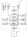
以下に、本発明によるストロボ装置の一つの実施形態を、図1を参照して説明する。 Hereinafter, one embodiment of a strobe device according to the present invention will be described with reference to FIG.
本実施形態によるストロボ装置10は、発光部12と、電池による電源部14と、駆動回路16と、発光部12の発光を制御するストロボ制御用マイクロコンピュータ20とを具備した電子制御式のものである。
The
発光部12は閃光放電管としてキセノン放電管13を具備している。キセノン放電管13は、長時間の繰り返しの発光に熱的に耐えるべく、ガラス管として石英製のものを用いられ、陰極用の電子放射性材料としてバリウムを含むものを用いられている。
The
駆動回路16は、DC−DCコンバータや主コンデンサ、トリガ回路、IGBT等によるスイッチングトランジスタ等を含み、電源部14よりの電力をDC−DCコンバータによって昇圧して閃光放電のための電気エネルギを主コンデンサに蓄え、ストロボ制御用マイクロコンピュータ20からの制御指令信号に従って発光部12の発光タイミングと発光量を定量的に設定する。
The
ストロボ制御用マイクロコンピュータ20は、定電圧回路22によって電圧調整された電源部14からの電力を供給されて動作する。ストロボ制御用マイクロコンピュータ20には、通信部24と、操作スイッチ群26と、表示部28と、受光センサ30と、ワイヤレスセンサ32と、シンクロコード接続部34とが接続されている。
The
通信部24は、ストロボ装置10が電子制御式のカメラ50のホットシューに装着されることによりカメラ50との間に各種情報の通信を行う。通信部24がカメラ50より受信するカメラ情報(信号)としては、TTL測光情報、シャッタ速度情報、シャッタボタン押下信号、シャッタ全開信号、シャッタ全閉信号等がある。
The
操作スイッチ群26は、使用者によって操作されるものであり、電源スイッチと、ファクションモードや各種のマニュアル設定値等を設定するマルチ設定スイッチとを具備している。マルチ設定スイッチが選択設定するファクションモードとしては、TTL自動調光モード、外部調光モード、マニュアルモード、マルチ発光モード、外部シンクロモード、ワイヤレスTTLモード等がある。
The
TTL自動調光モードは、シャッタボタンが押されて露光を開始する直前(シャッタが開く直前)に小光量による前発光(プリ発光)を行い、前発光時のカメラ50よりのTTL測光情報に基づいてその後のシャッタ開状態での露光のための発光の発光量を自動設定して主発光を行うモードである。
In the TTL automatic light control mode, pre-emission (pre-emission) with a small amount of light is performed immediately before the shutter button is pressed and exposure is started (immediately before the shutter is opened), and based on TTL photometry information from the
カメラ50がフォーカルプレンシャッタカメラの場合、シャッタ速度が所定以下の低速であると、先幕走行が完了して次に後幕走行が開始される間にシャッタが全開になった状態下で全面露光が行われ、これに対しシャッタ速度が所定以上の高速であると、先幕と後幕とが同時走行して先幕と後幕との間に形成されるスリットによって走査移動式の露光が行われるものがある。シャッタが全開になって全面露光する場合にはシャッタ全開時にTTL自動調光による一回閃光の主発光が行われる。これに対し走査移動式の露光の場合には、走査移動の全域に亘って比較的低い光量による発光がTTL自動調光のもとに連続して行われる。後者はハイスピードシンクロと呼ばれるものであり、この時の主発光の状態をフラット発光と呼ぶ。
When the
外部調光モードは、シャッタボタンが押されて露出が開始された時点から主発光を開始し、それと同時に受光センサ30によってリアルタイムで被写体からの反射光を計測し、その計測値の積分値が所定値になった時点で主発光を停止するモードである。
In the external light control mode, main light emission is started from the time when the shutter button is pressed and exposure is started, and at the same time, the reflected light from the subject is measured in real time by the
マニュアルモードは、マニュアル設定された発光量をもって一回閃光の主発光を行う。また、マルチ発光モードは、動被写体を分解写真(こま取り写真)を撮るような場合に用いられるモードであり、マニュアル設定された発光回数と発光周期(間隔)と一回発光毎の発光量をもって主発光を行うモードである。 In the manual mode, main flash is performed once with a manually set light emission amount. The multi-flash mode is a mode that is used when taking a disassembled photo of a moving subject (a top-down photo), and has a manually set flash count, flash cycle (interval), and flash output per flash. In this mode, main light emission is performed.
外部シンクロモードは、ホットシューによらずにシンクロコード接続部34に接続されたシンクロコードによってカメラ50と特定のシャッタ速度(X)設定のもとにシンクロを取って主発光を行うモードである。
The external sync mode is a mode in which main flash is performed by synchronizing with the
ワイヤレスTTLモードは、マルチストロボ撮影において、ストロボ装置10がカメラ50のホットシューに接続されるもう一つのストロボ装置(マスタ機)10以外にスレーブ機として別置きされた場合に、マスタ機よりワイヤレスセンサ32によってシャッタボタン情報とシャッタ情報とTTL測光情報とを受信してマスタ機と同一のTTL自動調光モードを実行するモードである。
In the wireless TTL mode, when the
表示部28は、液晶表示パネル等によって構成され、ファクションモード設定画面、マニュアル設定画面等を表示する。
The
ストロボ制御用マイクロコンピュータ20は、コンピュータプログラムを実行することにより、発光制御部40と、発熱限界制御部42と、発熱ポイント積算カウンタ44とを具現化する。
The
発光制御部40は上述した各ファクションモードにおける発光のタイミングと発光量とを設定して発光のための制御指令信号を駆動回路16に出力する。つまり、発光制御部40はカメラ50のシャッタが開いている状態下で行う発光を制御する。
The light
発熱限界制御部42は、発熱ポイント積算部44の発熱ポイント積算値Pcが所定値Pset以下であるか否かを判別し、発熱ポイント積算値Pcが所定値Pset以下である場合にはキセノン放電管13の発光を許可する信号を発光制御部40に出力し、発熱ポイント積算値Pcが所定値Pset以下でない場合にはキセノン放電管13の発光を禁止する信号を発光制御部40に出力する。
The heat generation
これにより、発熱ポイント積算値Pcが所定値Pset以下である場合には、上述した各ファクションモードにおける発光のタイミングと発光量をもってキセノン放電管13が発光するが、発熱ポイント積算値Pcが所定値Psetを超えるとキセノン放電管13は発光を禁止され、発光しない。
As a result, when the heat generation point integrated value Pc is equal to or less than the predetermined value Pset, the
発熱ポイント積算部44は、キセノン放電管13が発光した時にはその発光量に応じて数値化された発熱ポイント値Paを発熱ポイント積算値Pcに加算され、キセノン放電管13が発光していない発光休止時には、その発光休止時間に応じて数値化された放熱ポイント値Pbを減算される。
When the
キセノン放電管13が発光した時にはその発光量に応じてキセノン放電管13の温度が上がり、キセノン放電管13が発光していない時には、自然放熱によってキセノン放電管13の温度が下がるので、発熱ポイント積算部44の発熱ポイント積算値Pcは、連続発光やフラット発光の場合でも、閃光放電管13の温度に正しく相関することになる。
When the
発光量に応じた発熱ポイント値Paおよび発光休止時間に応じた放熱ポイント値Pbは、実験等により適正値に定めることができる。発熱ポイント積算部44は実験等により同定された発光量に応じた発熱ポイント値Paのデータテーブルを持っていればよい。このデータテーブルの一例を図2に示している。図2において、発光量1/1はフル発光、発光量1/32は最大制限発光である。
The heat generation point value Pa corresponding to the light emission amount and the heat dissipation point value Pb corresponding to the light emission pause time can be determined to be appropriate values through experiments or the like. The heat generation
発光休止時間に応じた放熱ポイント値Pbは単位時間によって決まる一定の値であり、単位時間当たり毎に発熱ポイント積算値Pcを所定値(放熱ポイント値Pb)をもってデクリメントすることが行われればよい。 The heat release point value Pb corresponding to the light emission pause time is a constant value determined by the unit time, and the heat generation point integrated value Pc may be decremented by a predetermined value (heat release point value Pb) every unit time.
この結果、キセノン放電管13の温度が所定値に達すると、キセノン放電管13の発光が禁止され、連続発光やフラット発光の場合でも、光放電管の熱的保護が適切に行われる。
As a result, when the temperature of the
また、発熱限界制御部42は、発熱ポイント積算値Pcが所定値Psetに達するか、あるいは近付くと、撮影感度を大きくする情報をカメラ50に出力する。
The heat generation
これにより、発熱ポイント積算値Pcが所定値Psetに達するか、あるいは近付くと高感度化によって発光量が低下し、キセノン放電管13の発光禁止の頻度が低下、あるいは発光禁止の時間が短縮する。
As a result, when the heat generation point integrated value Pc reaches or approaches the predetermined value Pset, the amount of light emission decreases due to high sensitivity, and the frequency of light emission inhibition of the
発熱限界制御部42及び発熱ポイント積算部44による発熱限界制御ルーチンを、図3を参照して説明する。発熱限界制御ルーチンは所定時間毎の繰り返し実行される時間割込ルーチンである。
A heat generation limit control routine by the heat generation
まず、カメラ50の情報によって発光の指令があるか否かを判別する(ステップS10)。発光の指令がない場合には、所定の発光休止時間が経過したとして、発熱ポイント積算部44の発熱ポイント積算値Pcを所定の放熱ポイント値Pbだけ減算する(ステップS15)。
First, it is determined whether there is a light emission command based on information from the camera 50 (step S10). If there is no light emission command, the heat generation point integrated value Pc of the heat generation
これに対し、発光の指令がある場合には、次の発光の発光量に対応する発熱ポイント値Paをデータテーブルより読み出し、発熱ポイント積算値Pcに発熱ポイント値Paを加算した値が予め定められている所定値(閾値)Pset以下であるか否かを判別する。 On the other hand, when there is a light emission command, a heat generation point value Pa corresponding to the next light emission amount is read from the data table, and a value obtained by adding the heat generation point value Pa to the heat generation point integrated value Pc is determined in advance. It is determined whether or not it is equal to or less than a predetermined value (threshold value) Pset.
(Pc+Pa)がPset以下でない場合には、キセノン放電管13の温度が危険温度になっているとして発光禁止の指令を発光制御部40に出力する。キセノン放電管13の温度が危険温度に達すると、キセノン放電管13は発光しない。この後、発熱ポイント積算値Pcを放熱ポイント値Pbだけ差し引いて発熱ポイント積算値Pcを更新し(ステップS15)、ルーチンを終了する。
If (Pc + Pa) is not equal to or lower than Pset, a light emission prohibition command is output to the light
これに対し、(Pc+Pa)がPset以下であれば、キセノン放電管13の温度が危険温度に達していないとして発光許可の指令を発光制御部40に出力する。これにより、キセノン放電管13が発光する。その後、発熱ポイント積算値Pcに発熱ポイント値Paを加算してポイント積算値Pcを更新し(ステップS13)、ルーチンを終了する。
On the other hand, if (Pc + Pa) is equal to or lower than Pset, a light emission permission command is output to the light
上述の発熱限界制御ルーチンが所定時間ごとに繰り返し実行されることにより、図3に示されているように、発熱ポイント積算値Pcが所定値Psetに達すると、発光禁止になるが、発光禁止によって発光休止が行われることにより発熱ポイント積算値Pcが低下し、次の発光が発光量Paをもって行われても、発熱ポイント積算値Pcが所定値Psetを超えない値にまで低下すると、即座に次の発光が行われる。これにより、最小限の発光禁止をもってキセノン放電管13の熱的保護が図られる。
By repeatedly executing the above-described heat generation limit control routine every predetermined time, as shown in FIG. 3, when the heat generation point integrated value Pc reaches the predetermined value Pset, the light emission is prohibited. When the light emission pause is performed, the heat generation point integrated value Pc decreases, and even if the next light emission is performed with the light emission amount Pa, if the heat generation point integrated value Pc decreases to a value not exceeding the predetermined value Pset, the next Is emitted. Thereby, thermal protection of the
発熱ポイント積算部44の発熱ポイント積算値Pcは、ストロボ装置10の電源がオフになっても保持され、電源再オン時に駆動回路16の主コンデンサの電圧が電源オフ期間の自然放電によって所定値になっていれば、電源オフの経過時間によってキセノン放電管13の温度が大気温度等まで十分低下しているとして、ゼロにリセットされればよい。
The heat generation point integrated value Pc of the heat generation
あるいは、ストロボ装置10の電源がオフになってストロボ制御用マイクロコンピュータ20を低消費電力モードで動作させ、電源オフ後の経過時間に応じて発熱ポイント積算値Pcをゼロになるまでデクリメントし、発熱ポイント積算値Pcがゼロになる前に電源が再オンされた場合には、その時点の発熱ポイント積算値Pcを使用する。
Alternatively, the
以上、本発明を、その一つの実施形態について説明したが、当業者であれば容易に理解できるように、本発明はこのような実施形態により限定されるものではなく、本発明の趣旨を逸脱しない範囲で適宜変更可能である。 Although the present invention has been described with respect to one embodiment thereof, the present invention is not limited to such an embodiment, as will be readily understood by those skilled in the art, and departs from the spirit of the present invention. It is possible to change appropriately within the range not to be.
たとえば、発熱限界制御部42による発熱限界制御は、キセノン放電管13が熱的問題を生じる高温状態になる虞がある連続発光やフラット発光の場合に行われてもよい。発光休止時間に応じた放熱ポイント値Pbは、キセノン放電管13の自然放熱特性に応じて連続した発光休止時間に応じた非線形の値であってもよい。
For example, the heat generation limit control by the heat generation
また、上記実施形態に示した構成要素は必ずしも全てが必須なものではなく、本発明の趣旨を逸脱しない限りにおいて適宜取捨選択することが可能である。 In addition, all the components shown in the above embodiment are not necessarily essential, and can be appropriately selected without departing from the gist of the present invention.
10 ストロボ装置
12 発光部
13 キセノン放電管
14 電源部
16 駆動回路
20 ストロボ制御用マイクロコンピュータ
22 定電圧回路
24 通信部
26 操作スイッチ群
28 表示部
30 受光センサ
32 ワイヤレスセンサ
34 シンクロコード接続部
40 発光制御部
42 発熱限界制御部
44 発熱ポイント積算カウンタ
50 カメラ
DESCRIPTION OF
Claims (2)
前記制御部は、
発光時には前記発光部の発光量に応じて数値化された発熱ポイント値を加算され、発光休止時には発光休止時間に応じて数値化された放熱ポイント値を減算される発熱ポイント積算部と、
前記発熱ポイント積算部の発熱ポイント積算値が所定値以下であるか否かを判別し、所定値以下である場合には前記発光部の発光を許可し、所定値以下でない場合には前記発光部の発光を禁止する発熱限界制御部と、
を有するストロボ装置。 A strobe device comprising: a light emitting unit including a flash discharge tube; and a control unit that inputs information related to opening / closing of a shutter from a camera and controls light emission of the light emitting unit,
The controller is
A heat generation point integration unit that adds a heat generation point value that is quantified according to the light emission amount of the light emission unit at the time of light emission, and that subtracts a heat dissipation point value that is converted to a numerical value according to the light emission stop time at the time of light emission stop,
It is determined whether or not the heat generation point integration value of the heat generation point integration unit is less than or equal to a predetermined value. If the heat generation point integration value is less than or equal to a predetermined value, light emission of the light emitting unit is permitted. A heat generation limit control unit that prohibits the emission of light,
Strobe device with.
Priority Applications (2)
| Application Number | Priority Date | Filing Date | Title |
|---|---|---|---|
| JP2012226892A JP2014077962A (en) | 2012-10-12 | 2012-10-12 | Strobe device |
| US14/050,433 US20140104809A1 (en) | 2012-10-12 | 2013-10-10 | Electronic Flash Device |
Applications Claiming Priority (1)
| Application Number | Priority Date | Filing Date | Title |
|---|---|---|---|
| JP2012226892A JP2014077962A (en) | 2012-10-12 | 2012-10-12 | Strobe device |
Publications (1)
| Publication Number | Publication Date |
|---|---|
| JP2014077962A true JP2014077962A (en) | 2014-05-01 |
Family
ID=50475143
Family Applications (1)
| Application Number | Title | Priority Date | Filing Date |
|---|---|---|---|
| JP2012226892A Pending JP2014077962A (en) | 2012-10-12 | 2012-10-12 | Strobe device |
Country Status (2)
| Country | Link |
|---|---|
| US (1) | US20140104809A1 (en) |
| JP (1) | JP2014077962A (en) |
Cited By (1)
| Publication number | Priority date | Publication date | Assignee | Title |
|---|---|---|---|---|
| JPWO2021107088A1 (en) * | 2019-11-29 | 2021-06-03 |
Families Citing this family (1)
| Publication number | Priority date | Publication date | Assignee | Title |
|---|---|---|---|---|
| JP7258589B2 (en) * | 2019-02-18 | 2023-04-17 | キヤノン株式会社 | Lighting device and its control method, imaging device |
Citations (4)
| Publication number | Priority date | Publication date | Assignee | Title |
|---|---|---|---|---|
| JP2005156793A (en) * | 2003-11-25 | 2005-06-16 | Canon Inc | Camera system |
| JP2006227474A (en) * | 2005-02-21 | 2006-08-31 | Sharp Corp | Color image forming apparatus |
| JP2008185699A (en) * | 2007-01-29 | 2008-08-14 | Canon Inc | Stroboscopic device |
| JP2009098477A (en) * | 2007-10-18 | 2009-05-07 | Canon Inc | Imaging apparatus |
Family Cites Families (8)
| Publication number | Priority date | Publication date | Assignee | Title |
|---|---|---|---|---|
| US5078039A (en) * | 1988-09-06 | 1992-01-07 | Lightwave Research | Microprocessor controlled lamp flashing system with cooldown protection |
| JPH06175188A (en) * | 1992-12-08 | 1994-06-24 | Nikon Corp | Electronic light control system and electronic flash device |
| JP4882159B2 (en) * | 2001-04-18 | 2012-02-22 | 株式会社ニコン | Flash control device and camera system |
| JP4350933B2 (en) * | 2002-03-29 | 2009-10-28 | パナソニック株式会社 | High pressure discharge lamp lighting method and high pressure discharge lamp apparatus |
| TWI386748B (en) * | 2008-07-18 | 2013-02-21 | E Pin Optical Industry Co Ltd | Camera with an array of light emitting diode (LED) flash |
| TWI389560B (en) * | 2010-05-14 | 2013-03-11 | Ability Entpr Co Ltd | Flashing control method for a digital camera |
| US20130004152A1 (en) * | 2011-06-30 | 2013-01-03 | Nikon Corporation | Accessory, camera, accessory control program, and camera control program |
| US8736710B2 (en) * | 2012-05-24 | 2014-05-27 | International Business Machines Corporation | Automatic exposure control for flash photography |
-
2012
- 2012-10-12 JP JP2012226892A patent/JP2014077962A/en active Pending
-
2013
- 2013-10-10 US US14/050,433 patent/US20140104809A1/en not_active Abandoned
Patent Citations (4)
| Publication number | Priority date | Publication date | Assignee | Title |
|---|---|---|---|---|
| JP2005156793A (en) * | 2003-11-25 | 2005-06-16 | Canon Inc | Camera system |
| JP2006227474A (en) * | 2005-02-21 | 2006-08-31 | Sharp Corp | Color image forming apparatus |
| JP2008185699A (en) * | 2007-01-29 | 2008-08-14 | Canon Inc | Stroboscopic device |
| JP2009098477A (en) * | 2007-10-18 | 2009-05-07 | Canon Inc | Imaging apparatus |
Cited By (3)
| Publication number | Priority date | Publication date | Assignee | Title |
|---|---|---|---|---|
| JPWO2021107088A1 (en) * | 2019-11-29 | 2021-06-03 | ||
| JP7314306B2 (en) | 2019-11-29 | 2023-07-25 | 富士フイルム株式会社 | SHUTTER CONTROL DEVICE, SHUTTER UNIT, IMAGING DEVICE, SHUTTER CONTROL METHOD, AND SHUTTER CONTROL PROGRAM |
| US11743594B2 (en) | 2019-11-29 | 2023-08-29 | Fujifilm Corporation | Shutter control device, shutter unit, imaging apparatus, shutter control method, and shutter control program |
Also Published As
| Publication number | Publication date |
|---|---|
| US20140104809A1 (en) | 2014-04-17 |
Similar Documents
| Publication | Publication Date | Title |
|---|---|---|
| US11079658B2 (en) | Lighting system and control thereof | |
| US7962030B2 (en) | Flash thermal feedback for camera auto-exposure | |
| KR20060090558A (en) | Digital camera with photoflash controller | |
| TW200534023A (en) | Digital camera capable of brightness and contrast control | |
| WO2012160658A1 (en) | Projector and dimming method | |
| US6498901B2 (en) | Flash photography system | |
| JP2014077962A (en) | Strobe device | |
| JP2017156625A (en) | Illumination device, control method thereof, and control program, and imaging apparatus | |
| JP6758861B2 (en) | Lighting equipment, its control method, control program, and imaging device | |
| KR101014622B1 (en) | Led illuminating system for photography and the control method | |
| TWI280819B (en) | Light source device and power supply thereof | |
| JP2003337372A (en) | Illuminator for underwater photography with digital camera | |
| JP5224757B2 (en) | Strobe device, imaging device, and camera system | |
| JP5544752B2 (en) | Remote lighting control device and remote lighting device system | |
| JP2015191000A (en) | Imaging device, flash device and flash photographing system | |
| JP2020134653A (en) | Lighting system, control method for the same and imaging device | |
| JP2013088765A (en) | Lighting device | |
| US20240089575A1 (en) | Illumination apparatus for reducing temperature rise due to light emission and control method | |
| KR200421266Y1 (en) | Light emitting apparatus for camera capable of control lightness | |
| JPH11119304A (en) | Camera system | |
| JP2011059406A (en) | Photographing system, and imaging apparatus | |
| JP2014010304A (en) | Strobe device | |
| JP2017142426A (en) | Lens device and camera device | |
| JP2001311988A (en) | Strobe light control system and camera equipped with strobe | |
| KR100245007B1 (en) | Flash charge control apparatus and method according to battery voltage |
Legal Events
| Date | Code | Title | Description |
|---|---|---|---|
| A621 | Written request for application examination |
Free format text: JAPANESE INTERMEDIATE CODE: A621 Effective date: 20150713 |
|
| A977 | Report on retrieval |
Free format text: JAPANESE INTERMEDIATE CODE: A971007 Effective date: 20160617 |
|
| A131 | Notification of reasons for refusal |
Free format text: JAPANESE INTERMEDIATE CODE: A131 Effective date: 20160705 |
|
| A02 | Decision of refusal |
Free format text: JAPANESE INTERMEDIATE CODE: A02 Effective date: 20170307 |