JP2014070927A - Test piece and method for delayed fracture characteristic evaluation of ultra-high strength surface treated steel plate - Google Patents
Test piece and method for delayed fracture characteristic evaluation of ultra-high strength surface treated steel plate Download PDFInfo
- Publication number
- JP2014070927A JP2014070927A JP2012215358A JP2012215358A JP2014070927A JP 2014070927 A JP2014070927 A JP 2014070927A JP 2012215358 A JP2012215358 A JP 2012215358A JP 2012215358 A JP2012215358 A JP 2012215358A JP 2014070927 A JP2014070927 A JP 2014070927A
- Authority
- JP
- Japan
- Prior art keywords
- test piece
- delayed fracture
- test
- ultra
- treated steel
- Prior art date
- Legal status (The legal status is an assumption and is not a legal conclusion. Google has not performed a legal analysis and makes no representation as to the accuracy of the status listed.)
- Granted
Links
Images


Landscapes
- Investigating Strength Of Materials By Application Of Mechanical Stress (AREA)
- Testing Resistance To Weather, Investigating Materials By Mechanical Methods (AREA)
- Investigating And Analyzing Materials By Characteristic Methods (AREA)
Abstract
Description
本発明は、自動車部材や建築用材料等に好適な超高強度表面処理鋼板に係り、とくに超高強度表面処理鋼板の遅れ破壊特性評価用試験片の改善に関する。なお、ここでいう「超高強度」とは、引張強さ:1180MPa以上である場合をいうものとする。また、ここでいう「表面処理鋼板」としては、Zn系電気めっき鋼板、Zn系溶融めっき鋼板、Al系めっき鋼板、Ni系めっき鋼板が例示できる。 The present invention relates to an ultra-high-strength surface-treated steel sheet suitable for automobile members, building materials, and the like, and more particularly to improvement of a specimen for evaluating delayed fracture characteristics of an ultra-high-strength surface-treated steel sheet. Here, “ultra-high strength” refers to the case where the tensile strength is 1180 MPa or more. Examples of the “surface-treated steel sheet” herein include Zn-based electroplated steel sheets, Zn-based hot dip plated steel sheets, Al-based plated steel sheets, and Ni-based plated steel sheets.
近年、地球環境の保全という観点から、自動車の燃費向上が強く要望されている。このため、自動車メーカーでは、車体の軽量化が重要な課題となっており、自動車部品の高強度化による薄肉化、軽量化が検討されている。例えば、バンパーやピラーなどの耐衝突特性を必要とする部品やその他の補強部品には、引張強さが1180MPa以上の超高強度鋼板が使用され始めている。しかしこの場合、薄肉化によって腐食代が減少するため、腐食環境が厳しいと想定される部品には、表面処理を施された超高強度鋼板(超高強度表面処理鋼板)の使用が検討されている。 In recent years, there has been a strong demand for improving the fuel efficiency of automobiles from the viewpoint of conservation of the global environment. For this reason, reducing the weight of the vehicle body has become an important issue for automobile manufacturers, and the reduction of thickness and weight by increasing the strength of automobile parts is being studied. For example, ultra-high-strength steel sheets with a tensile strength of 1180 MPa or more are beginning to be used for parts that require impact resistance such as bumpers and pillars and other reinforcing parts. However, in this case, since the corrosion allowance is reduced by thinning, the use of ultra-high-strength steel sheets that have been surface-treated (ultra-high-strength surface-treated steel sheets) is being considered for parts that are expected to have a severe corrosive environment. Yes.
引張強さが1180MPaを超える超高強度鋼板では、従来から、遅れ破壊が発生しやすいという問題があり、超高強度鋼板を使用するにあたっては、超高強度鋼板の遅れ破壊特性を正確に評価して、遅れ破壊の発生を未然に防ぐことが重要となる。「遅れ破壊」は、水素脆化の一種であり、鋼板の使用開始後の数ヶ月から数年後に突如として破壊する現象である。 Conventionally, ultra-high-strength steel sheets with a tensile strength exceeding 1180 MPa have a problem that delayed fracture is likely to occur. Therefore, it is important to prevent delayed destruction. “Delayed fracture” is a type of hydrogen embrittlement, and is a phenomenon that suddenly breaks months to years after the start of use of a steel sheet.
遅れ破壊の評価方法については、例えば、非特許文献1に、各種の遅れ破壊の加速試験方法が提案されている。しかし、非特許文献1に記載された各種の試験方法では、試験結果にばらつきが生じる場合があり、試験精度の向上が課題とされていた。
このような問題に対し、例えば、特許文献1に、耐遅れ破壊特性評価方法が記載されている。特許文献1に記載された技術は、棒状の試験片本体と、被水素チャージ部位として試験片本体の周方向に拡張して形成される鍔部と、引張試験時の応力集中部として試験片本体の周方向全周に渡って形成される切欠部と、によって形成される試験片を用いて、鋼材の耐遅れ破壊特性を評価する耐遅れ破壊特性評価方法である。特許文献1に記載された技術は、鍔部を酸性溶液に浸漬して、試験片に水素をチャージする水素チャージ工程と、試験片からの水素の放出を抑制するために試験片の全表面にカドミウムを塗布するカドミウム塗布工程と、試験片の両端を引っ張り、切欠部を破断させる破断工程と、を行う耐遅れ破壊特性評価方法である。そして特許文献1に記載された技術では、試験片の形状W,L、浸漬時間Tを変更して、耐遅れ破壊特性を評価することに特徴があり、鋼材の耐遅れ破壊特性を正確かつ簡易に評価することができるとしている。
As for the delayed fracture evaluation method, for example, Non-Patent
For such a problem, for example,
また、特許文献2には、引張強さが980MPa以上の高強度溶融亜鉛めっき鋼板の耐遅れ破壊性評価方法が記載されている。特許文献2に記載された技術では、めっき鋼板の素材である鋼板から、試験片を採取し、該試験片を電解液中に浸漬し、電解液の電解によって発生する水素を試験片に導入する水素導入工程と、水素を導入した試験片に、亜鉛を主体とするめっき層を5〜100μmの厚さで形成するめっき層形成工程と、めっき層が形成された試験片に、450〜600℃で5〜600s間の水素拡散処理を行う水素拡散処理工程と、水素拡散処理を行った試験片に対し、耐遅れ破壊性試験を行う耐遅れ破壊性試験工程とを行うことを特徴としており、耐遅れ破壊性を迅速に、かつ簡便に評価できるとしている。
また、特許文献3には、薄鋼板水素脆化評価方法が記載されている。特許文献3に記載された技術は、電解槽と、定荷重発生手段と、電流発生手段とからなる薄鋼板用水素脆化評価装置を利用して、薄鋼板試験片に水素チャージを行いながら、引張応力を負荷する薄鋼板水素脆化評価方法である。特許文献3に記載された技術では、電解槽内に、定荷重発生手段からの応力を薄鋼板試験片に伝達する治具と、薄鋼板試験片に水素チャージを行うための電極を設け、治具と薄鋼板試験片とを連結する支持ピンを部分ジルコニアまたはサイアロンとすることにより、薄鋼板の水素脆化特性を精度よく評価できるとしている。
特許文献1に記載された技術では、試験片にチャージされた水素が試験片から放出されるのを抑制するために、試験片の全表面にカドミウムを塗布している。塗布されたカドミウムは鋼板への水素の出入を抑制するが、しかし、塗布されたカドミウムが、試験片を腐食試験溶液に浸漬した際に、試験溶液と化学反応を起こし、試験鋼材の遅れ破壊特性を正当に評価することが困難となるという問題があった。
In the technique described in
また、特許文献2に記載された技術では、電解液の電解によって発生する水素を試験片にチャージしたのちにめっき層を形成している。したがって、チャージされた水素に加えて、めっき層形成時に侵入した水素を含めて遅れ破壊特性を評価しており、遅れ破壊特性に及ぼす水素チャージ時の水素量の影響のみを明確に評価することができないという問題があった。
Moreover, in the technique described in
また、特許文献3に記載された技術は、表面処理鋼板における遅れ破壊特性の評価を行うことを目的としておらず、とくに遅れ破壊特性に及ぼす表面処理皮膜の影響を評価できるまでの配慮がなされていないという問題があった。
本発明は、かかる従来技術の問題を解決し、表面に形成された皮膜(表面処理皮膜)の水素侵入特性を適正に反映し、引張強さ1180MPa以上の超高強度表面処理鋼板の遅れ破壊特性の正確な評価に寄与できる、超高強度表面処理鋼板の遅れ破壊特性評価用試験片を提供することを目的とする。
In addition, the technique described in
The present invention solves such problems of the prior art, appropriately reflects the hydrogen penetration characteristics of the film (surface treatment film) formed on the surface, and delayed fracture characteristics of ultra high strength surface treated steel sheet with a tensile strength of 1180 MPa or more. It is an object of the present invention to provide a test piece for evaluating delayed fracture characteristics of an ultra-high-strength surface-treated steel sheet that can contribute to accurate evaluation.
また、その試験片を利用した、超高強度表面処理鋼板の水素侵入特性、遅れ破壊特性を適正に評価できる超高強度表面処理鋼板の水素侵入特性評価方法、および超高強度表面処理鋼板の遅れ破壊特性評価方法を提供することを目的とする。 In addition, the hydrogen penetration characteristics evaluation method for ultra-high-strength surface-treated steel sheets that can properly evaluate the hydrogen penetration characteristics and delayed fracture characteristics of ultra-high-strength surface-treated steel sheets, and the delay of ultra-high-strength surface-treated steel sheets. An object is to provide a method for evaluating fracture characteristics.
本発明者らは、上記した目的を達成するために、超高強度表面処理鋼板の遅れ破壊特性を評価するにあたり、試験片を試験液に浸漬した際に試験液から試験片に侵入し、遅れ破壊発生に寄与する水素の侵入挙動について鋭意検討した。その結果、試験片に侵入する水素は、試験片表裏面から侵入する量に比べて、試験片端面から侵入する量が格段に多くなることに思い至った。というのは、試験片端面は、剪断加工や機械加工により仕上げられ、活性な面となっているため、水素が侵入しやすいと考えられる。そのため、表面処理鋼板のような表面に皮膜が形成されている場合には、表面皮膜を介して侵入する水素の量より端面から侵入する水素の量が多くなることになり、そのため、得られた試験結果(遅れ破壊特性)が、遅れ破壊特性に及ぼす表面皮膜の影響を正確に反映した結果とならないことになる。 In order to achieve the above-mentioned object, the present inventors, when evaluating the delayed fracture characteristics of the ultra-high-strength surface-treated steel sheet, penetrated the test piece from the test solution when the test piece was immersed in the test solution. We have intensively studied the penetration behavior of hydrogen that contributes to the occurrence of fracture. As a result, it came to mind that the amount of hydrogen that penetrates into the test piece invades from the end surface of the test piece is significantly larger than the amount of hydrogen that enters from the front and back surfaces of the test piece. This is because the end surface of the test piece is finished by shearing or machining and is an active surface, so that hydrogen is likely to enter. Therefore, when a film is formed on a surface such as a surface-treated steel sheet, the amount of hydrogen entering from the end face is larger than the amount of hydrogen entering through the surface film, and thus obtained. Test results (delayed fracture characteristics) will not accurately reflect the effect of the surface coating on delayed fracture characteristics.
そこで、表面処理鋼板の遅れ破壊特性を正確に評価するためには、試験片端面からの水素の侵入を抑制し、表面皮膜が形成された面からのみ水素を侵入させることが必要であり、本発明者らは、使用する試験片の端面を水素を透過しない塗膜で被覆することを思い付いた。更なる実験から、試験片端面に被覆する塗膜としては、合成樹脂の塗布による塗膜がよいことを見出した。 Therefore, in order to accurately evaluate the delayed fracture characteristics of the surface-treated steel sheet, it is necessary to suppress the intrusion of hydrogen from the end face of the test piece and to infiltrate only from the surface on which the surface film is formed. The inventors have come up with the idea that the end face of the test piece to be used is covered with a coating film that does not allow hydrogen permeation. From further experiments, it was found that a coating film formed by applying a synthetic resin is good as a coating film to be coated on the end face of the test piece.
本発明は、かかる知見に基づき、更なる検討を加えて完成されたものである。すなわち、本発明の要旨はつぎのとおりである。
(1)引張強さ:1180MPa以上の超高強度を有する超高強度表面処理鋼板からなる遅れ破壊特性評価用の試験片であって、該試験片の端面表面を、JIS B 0601−2001に規定される算術平均粗さRaで6.3μm以下の表面粗さを有する表面とし、さらに該端面表面に合成樹脂塗膜を有することを特徴とする超高強度表面処理鋼板の遅れ破壊特性評価用試験片。
(2)(1)に記載された試験片を、無負荷の状態で試験液に浸漬して、試験片内に水素をチャージし、所定時間内に試験片にチャージされた水素量を測定し、該水素量により水素侵入特性を評価することを特徴とする超高強度表面処理鋼板の水素侵入特性評価方法。
(3)(1)に記載された遅れ破壊特性評価用の試験片を、試験液に浸漬し、定荷重による引張応力を負荷して遅れ破壊特性を評価するにあたり、前記試験片の中央部所定領域を容器に保持された前記試験液に浸漬し、該試験液に浸漬されない前記試験片の両端部から前記引張応力を負荷し、破断時間を求め、遅れ破壊特性を評価することを特徴とする超高強度表面処理鋼板の遅れ破壊特性評価方法。
(4)(1)に記載された遅れ破壊特性評価用の試験片を、曲げ応力が負荷された状態で試験液に浸漬し、破断時間を求め、遅れ破壊特性を評価することを特徴とする超高強度表面処理鋼板の遅れ破壊特性評価方法。
The present invention has been completed on the basis of such findings and further studies. That is, the gist of the present invention is as follows.
(1) Tensile strength: A test piece for evaluating delayed fracture characteristics composed of a super-high strength surface-treated steel sheet having an ultra-high strength of 1180 MPa or more. The end surface of the test piece is specified in JIS B 0601-2001. Test piece for evaluating delayed fracture characteristics of ultra-high-strength surface-treated steel sheet, characterized in that the surface has a surface roughness of 6.3 μm or less with an arithmetic average roughness Ra, and further has a synthetic resin coating on the end face surface .
(2) The test piece described in (1) is immersed in a test solution in an unloaded state, hydrogen is charged in the test piece, and the amount of hydrogen charged in the test piece within a predetermined time is measured. A method for evaluating hydrogen penetration characteristics of an ultra-high-strength surface-treated steel sheet, characterized by evaluating hydrogen penetration characteristics based on the amount of hydrogen.
(3) When the delayed fracture characteristics evaluation test piece described in (1) is immersed in a test solution and a tensile stress due to a constant load is applied to evaluate delayed fracture characteristics, a predetermined central portion of the test piece is determined. A region is immersed in the test solution held in a container, the tensile stress is applied from both ends of the test piece not immersed in the test solution, a fracture time is obtained, and delayed fracture characteristics are evaluated. Method for evaluating delayed fracture characteristics of ultra-high strength surface-treated steel sheets.
(4) The specimen for evaluating delayed fracture characteristics described in (1) is immersed in a test solution under a bending stress, the fracture time is obtained, and the delayed fracture characteristics are evaluated. Method for evaluating delayed fracture characteristics of ultra-high strength surface-treated steel sheets.
本発明によれば、引張強さ:1180MPa以上の超高強度表面処理鋼板の遅れ破壊特性を表面皮膜の影響を含め適切に評価でき、超高強度表面処理鋼板の使用拡大に大きく寄与でき、産業上格段の効果を奏する。また、本発明によれば、厳しい腐食環境下で使用される超高強度表面処理鋼板の遅れ破壊特性を適切に評価でき、例えば自動車部品等で、使用中に遅れ破壊が発生するという事故を未然に防止できるという効果もある。 According to the present invention, it is possible to appropriately evaluate the delayed fracture characteristics of an ultra-high-strength surface-treated steel sheet having a tensile strength of 1180 MPa or more, including the effect of the surface coating, and can greatly contribute to the expansion of use of the ultra-high-strength surface-treated steel sheet. Has an exceptional effect. In addition, according to the present invention, the delayed fracture characteristics of an ultra-high-strength surface-treated steel sheet used in a severe corrosive environment can be appropriately evaluated. For example, an accident in which delayed fracture occurs during use in an automotive part or the like can occur. There is also an effect that can be prevented.
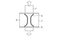
本発明になる超高強度表面処理鋼板の遅れ破壊特性評価用試験片の形状は、遅れ破壊試験に対応した種々の形状となるが、試験片の少なくとも試験液に浸漬される部位の端面表面には、水素の侵入を防止するための合成樹脂塗膜が形成される。本発明遅れ破壊特性評価用試験片の一例を図1に示す。図1は、定荷重方式の遅れ破壊評価試験に使用する試験片の例で、試験片1は、容器7に保持された試験液8に浸漬され、浸漬された部位の端面には、合成樹脂塗膜5が形成される。
The shape of the test specimen for delayed fracture property evaluation of the ultra-high strength surface-treated steel sheet according to the present invention has various shapes corresponding to the delayed fracture test, but at least on the end surface of the part immersed in the test solution of the test specimen. Forms a synthetic resin coating to prevent hydrogen from entering. An example of the test piece for evaluating delayed fracture characteristics of the present invention is shown in FIG. FIG. 1 is an example of a test piece used for a constant load type delayed fracture evaluation test. The
本発明遅れ破壊特性評価用試験片では、まず、合成樹脂塗膜の密着性を向上させるために、少なくとも合成樹脂塗膜を形成する端面表面を、JIS B 0601−2001に規定される算術平均粗さRaで6.3μm以下の表面粗さを有する面とする。
試験片端面は、形成される合成樹脂塗膜を十分な密着性をもって形成するために、Raで6.3μm以下の適正な範囲の表面粗さに調整する。試験片端面の表面粗さがRaで6.3μmを超えて大きくなると、塗膜を厚くする必要があり、乾燥しにくいため、塗膜と試験片の密着性が低下し、試験液に浸漬中に剥離しやすくなる。このため、試験片端面の表面粗さをRaで6.3μm以下に限定した。一方、Raで0.1μm未満となると、端面が平滑になりすぎて、表面に形成する塗膜の密着性が低下する。このため、試験片端面の表面粗さはRaで0.1μm以上とすることが望ましい。
In the test piece for evaluation of delayed fracture characteristics according to the present invention, first, in order to improve the adhesion of the synthetic resin coating film, at least the surface of the end surface on which the synthetic resin coating film is formed has an arithmetic average roughness defined in JIS B 0601-2001. The surface has a surface roughness of 6.3 μm or less in thickness Ra.
The end face of the test piece is adjusted to a surface roughness in an appropriate range of Ra of 6.3 μm or less in order to form the formed synthetic resin coating film with sufficient adhesion. If the surface roughness of the test piece end surface is larger than 6.3μm in Ra, it is necessary to thicken the coating, and it is difficult to dry. Easy to peel. For this reason, the surface roughness of the end face of the test piece was limited to 6.3 μm or less in Ra. On the other hand, if the Ra is less than 0.1 μm, the end face becomes too smooth, and the adhesion of the coating film formed on the surface decreases. For this reason, the surface roughness of the end face of the test piece is desirably 0.1 μm or more in Ra.
なお、合成樹脂塗膜を形成する端面表面の表面粗さを調整する手段としては、とくに限定する必要はないが、フライスや旋盤等の機械加工による切削加工、研削加工、放電加工、サンドペーパー等による手研磨などの加工方法により、上記した表面粗さを有する端面表面に調整することができる。
上記した表面粗さに調整したのち、試験片端面表面には合成樹脂塗膜が形成される。合成樹脂塗膜の形成方法は、特に限定する必要はないが、塗布等により形成することが簡便性の観点から好ましい。塗膜形成に使用する合成樹脂の種類は、とくに限定する必要はないが、簡便性の観点から熱硬化性樹脂とすることが好ましい。なお、熱硬化性樹脂であれば、シリコン樹脂、エポキシ樹脂、変性エポキシ樹脂、タールエポキシ樹脂等が例示できる。
In addition, as a means for adjusting the surface roughness of the end surface to form the synthetic resin coating film, it is not necessary to specifically limit, but cutting, grinding, electric discharge, sandpaper, etc. by machining such as a milling machine or a lathe It can be adjusted to the end face surface having the above-described surface roughness by a processing method such as manual polishing.
After adjusting to the above-described surface roughness, a synthetic resin coating film is formed on the surface of the end face of the test piece. The method for forming the synthetic resin coating film is not particularly limited, but is preferably formed by coating or the like from the viewpoint of simplicity. The type of synthetic resin used for forming the coating film is not particularly limited, but is preferably a thermosetting resin from the viewpoint of simplicity. In addition, if it is a thermosetting resin, a silicon resin, an epoxy resin, a modified epoxy resin, a tar epoxy resin etc. can be illustrated.
使用する合成樹脂を、例えば、熱硬化性樹脂とする場合には、刷毛等を用いて試験片端面に塗布し、加熱によって硬化させて、所定の塗膜厚さとすることが好ましい。なお、塗膜の厚さは50〜700μm(乾燥厚さ)とすることが塗膜の耐剥離性の観点から好ましい。
上記した本発明試験片を用いて、遅れ破壊試験を実施すれば、端面からの水素侵入が防止でき、表面処理皮膜の影響を考慮して超高強度鋼板の耐遅れ破壊特性を十分適正に評価できる。とくに表面処理鋼板では、耐遅れ破壊特性に及ぼす皮膜の影響を適正に評価できる。
When the synthetic resin to be used is, for example, a thermosetting resin, it is preferably applied to the end face of the test piece using a brush or the like and cured by heating to have a predetermined coating film thickness. In addition, it is preferable from a viewpoint of the peeling resistance of a coating film that the thickness of a coating film shall be 50-700 micrometers (dry thickness).
If a delayed fracture test is performed using the above-described test piece of the present invention, hydrogen penetration from the end face can be prevented, and the delayed fracture resistance of the ultra-high strength steel sheet is sufficiently adequately evaluated in consideration of the effect of the surface treatment film. it can. Especially for surface-treated steel sheets, the effect of the coating on delayed fracture resistance can be properly evaluated.
つぎに、図1に示す形状で端面に合成樹脂塗膜を形成した、定荷重遅れ破壊試験片を、定荷重遅れ破壊試験機に装着し、遅れ破壊試験を実施すれば、端面からの水素侵入が防止でき、超高強度表面処理鋼板の遅れ破壊特性に及ぼす表面処理皮膜の影響を適正に評価することができる。なおこの場合、図1に示すように、試験片1の中央部所定領域、すなわち平行部近傍を、容器7に保持された試験液8に浸漬することが好ましい。これによれば、試験液に浸漬されない両端部から所定の種々の引張応力を負荷でき、定荷重遅れ破壊試験が簡便で容易となる。なお、容器7には保持した試験液8が漏れないようにパッキン6等が付設されていることは言うまでもない。
Next, if a constant load delayed fracture test piece with a synthetic resin coating film formed on the end face in the shape shown in FIG. 1 is mounted on a constant load delayed fracture tester and a delayed fracture test is performed, hydrogen penetration from the end face And the influence of the surface treatment film on the delayed fracture characteristics of the ultra high strength surface treated steel sheet can be appropriately evaluated. In this case, as shown in FIG. 1, it is preferable to immerse a predetermined region at the center of the
また、端面に合成樹脂塗膜5を形成した、例えば図3に示す形状の4点曲げ試験片を、図4に示す4点曲げ治具に装着し、試験片1に所定の曲げ応力を負荷した状態で、所定時間、試験液中に浸漬し、遅れ破壊発生状況を調査する4点曲げ遅れ破壊試験を実施すれば、端面からの水素侵入が防止でき、超高強度表面処理鋼板の遅れ破壊特性に及ぼす表面処理皮膜の影響を適正に評価することができる。
Further, for example, a four-point bending test piece having the shape shown in FIG. 3 with the
なお、この4点曲げ治具では、試験片(4点曲げ試験片)1を、試験台3に4点で固定し、ネジ4の締込み量により試験片への負荷応力を調整できる。なお、試験片1と試験台3とは、ガラス製絶縁治具2で絶縁されることは言うまでもない。試験片が試験台にセットされた状態で試験液中に浸漬して、試験に供する。
また、上記した本発明試験片を用いれば、表面処理鋼板の水素侵入特性を適正に評価できる。 例えば、表面処理鋼板から、図2に示す形状を有する試験片を採取し、試験片端面に合成樹脂塗膜を形成し、無負荷で試験液中に浸漬し、所定時間保持したのち、試験片に侵入した水素量を分析すれば、表面処理鋼板の水素侵入特性に及ぼす表面処理皮膜の影響を適正に評価することができる。
In this four-point bending jig, the test piece (four-point bending test piece) 1 is fixed to the test table 3 at four points, and the load stress on the test piece can be adjusted by the tightening amount of the
Moreover, if the above-mentioned test piece of the present invention is used, the hydrogen penetration property of the surface-treated steel sheet can be properly evaluated. For example, a test piece having the shape shown in FIG. 2 is collected from the surface-treated steel sheet, a synthetic resin coating film is formed on the end face of the test piece, immersed in the test solution without load, and held for a predetermined time. By analyzing the amount of hydrogen that has penetrated into the surface, the influence of the surface treatment film on the hydrogen penetration properties of the surface-treated steel sheet can be properly evaluated.
なお、上記した各評価試験で使用される試験液は、例えば、pH:3.0以下に調整した塩酸や、pH=3.0以下の緩衝液とすることが好ましい。緩衝液の種類としては、とくに限定する必要はないが、塩酸-酢酸ナトリウム緩衝液、クエン酸緩衝液などが例示できる。また、チオシアン酸アンモニウム緩衝液はpH=5程度であるが、めっき層の溶解を抑制し、表面処理鋼板の試験液としては好ましいといえる。 In addition, it is preferable that the test solution used in each evaluation test described above is, for example, hydrochloric acid adjusted to pH: 3.0 or less or a buffer solution having pH = 3.0 or less. The type of buffer solution is not particularly limited, and examples thereof include hydrochloric acid-sodium acetate buffer solution and citrate buffer solution. Moreover, although the ammonium thiocyanate buffer solution has a pH of about 5, it can be said that it is preferable as a test solution for the surface-treated steel sheet because it suppresses dissolution of the plating layer.
また、試験液への浸漬時間(試験時間)は、特に限定されるものではないが、ある程度の浸漬時間で水素の侵入量は飽和するため、浸漬時間(試験時間)は最長でも100 h程度とするのが好ましい。
なお、表面処理鋼板の遅れ破壊特性の評価ではないが、非特許文献1に記載された遅れ破壊特性評価試験方法で使用する試験片においても、評価領域以外の領域に合成樹脂塗膜を形成することにより、評価領域以外からの水素侵入を抑制し、評価領域の遅れ破壊特性を適正に評価できる。
In addition, the immersion time (test time) in the test solution is not particularly limited, but the immersion time (test time) is about 100 h at the longest because the hydrogen penetration amount is saturated at a certain immersion time. It is preferable to do this.
In addition, although it is not evaluation of the delayed fracture characteristic of the surface-treated steel sheet, a synthetic resin coating film is formed in a region other than the evaluation region even in the test piece used in the delayed fracture property evaluation test method described in
(実施例1)
表1に、組成と引張特性とを示す超高強度鋼板(板厚:1.2mm)を素材とした。
まず、表1に示す組成、引張特性を有する超高強度表面処理鋼板Aから、図5に示す寸法形状の定荷重遅れ破壊試験片を採取した。得られた試験片の端面表面を、サンドペーパーの番手を変化させて、算術平均粗さRaが0.1〜25.0μmの範囲内の表面粗さとなるように、調整した。なお、鋼板Aは、Zn−Niめっきを表面に形成した超高強度表面処理鋼板である。
Example 1
In Table 1, an ultra-high strength steel plate (thickness: 1.2 mm) showing composition and tensile properties was used as a raw material.
First, from the ultrahigh strength surface-treated steel sheet A having the composition and tensile properties shown in Table 1, a constant load delayed fracture test piece having the dimensions shown in FIG. 5 was collected. The surface of the end face of the obtained test piece was adjusted so that the arithmetic average roughness Ra was a surface roughness in the range of 0.1 to 25.0 μm by changing the sandpaper count. The steel plate A is an ultra-high strength surface-treated steel plate having Zn—Ni plating formed on the surface.
ついで、表面粗さを調整された端面表面に、変性エポキシ樹脂(商品名:タフプライマー、ナトコ(株)製)を刷毛で、乾燥膜厚で約300μmとなるように塗布し、塗布後、130℃×20minの乾燥処理を行った。
得られた定荷重遅れ破壊試験片を定荷重試験機にセットした。なお、図1に示すように、試験片の平行部のみが試験液に浸漬されるように、試験液8を保持した容器7を装着した。試験液はpH=1に調整された塩酸-酢酸ナトリウム緩衝液を使用し、試験応力は967MPaとし、塗膜の剥離時間を、最長100hまで観察した。
Next, a modified epoxy resin (trade name: Tough Primer, manufactured by NATCO Co., Ltd.) was applied to the end surface with the adjusted surface roughness with a brush so that the dry film thickness was about 300 μm. A drying treatment at 20 ° C. for 20 minutes was performed.
The obtained constant load delayed fracture test piece was set in a constant load tester. In addition, as shown in FIG. 1, the
得られた結果を表2に示す。 The obtained results are shown in Table 2.

端面の算術平均粗さRaを6.3μm以下にした本発明例はいずれも、密着力が強く、試験液に100h以上浸漬しても塗膜の剥離は認められていない。一方、本発明範囲を外れる比較例は、100h未満で塗膜の剥離が生じている。
(実施例2)
表1に示す組成を有し、ほぼ同等の引張特性を有する超高強度鋼板で、表面に異なる表面処理皮膜を有する3種の鋼板を素材とした。鋼板Aは、表面にZn−Niめっき皮膜を有する超高強度表面処理鋼板であり、鋼板Bは、表面処理皮膜なしの超高強度鋼板である。また、鋼板Cは、表面にAl−Siめっき皮膜を有する超高強度表面処理鋼板である。
The examples of the present invention in which the arithmetic average roughness Ra of the end face is 6.3 μm or less have high adhesion, and the coating film is not peeled even when immersed in the test solution for 100 hours or longer. On the other hand, in the comparative example outside the scope of the present invention, the coating film peels off in less than 100 hours.
(Example 2)
Three types of steel sheets having the compositions shown in Table 1 and having substantially the same tensile properties and having different surface treatment films on the surface were used as materials. Steel plate A is an ultra-high strength surface-treated steel plate having a Zn-Ni plating film on its surface, and steel plate B is an ultra-high strength steel plate without a surface treatment film. Steel plate C is an ultra-high strength surface-treated steel plate having an Al-Si plating film on the surface.
これら素材から、図5に示す寸法形状の定荷重遅れ破壊試験片を採取した。そして、得られた試験片の端面表面をサンドペーパー仕上で、算術平均粗さRaが約1.6μmとなるように、調整した。ついで、実施例1と同様に、端面表面に、変性エポキシ樹脂(商品名:タフプライマー、ナトコ(株)製)を、刷毛で乾燥膜厚で約300μmとなるように塗布した。塗布後、130℃で20minの乾燥処理を行った。なお、一部の試験片では、端面における合成樹脂塗膜形成を行わなかった。 From these materials, the constant load delayed fracture test pieces having the dimensions shown in FIG. 5 were collected. And the end surface of the obtained test piece was sandpaper finished and adjusted so that the arithmetic average roughness Ra was about 1.6 μm. Next, in the same manner as in Example 1, a modified epoxy resin (trade name: Tough Primer, manufactured by NATCO Co., Ltd.) was applied to the end surface with a brush so that the dry film thickness was about 300 μm. After the application, a drying process was performed at 130 ° C. for 20 minutes. In some of the test pieces, the synthetic resin coating film was not formed on the end face.
得られた定荷重遅れ破壊試験片を、実施例1と同様に、平行部が試験液に浸漬するように定荷重試験機にセットし、種々の引張応力を負荷して試験片が破断する時間(破断時間)を求めた。試験液は、実施例1と同様に、pH=1に調整された塩酸-酢酸ナトリウム緩衝液とした。なお、試験時間は100hまでとした。
得られた結果を表3に、それらを纏めて図6に示す。
As in Example 1, the obtained constant load delayed fracture test piece was set in a constant load test machine so that the parallel portion was immersed in the test solution, and the test piece was broken by applying various tensile stresses. (Breaking time) was determined. The test solution was a hydrochloric acid-sodium acetate buffer adjusted to pH = 1 in the same manner as in Example 1. The test time was up to 100h.
The results obtained are shown in Table 3 and are summarized in FIG.
図6から、端面に合成樹脂塗膜を形成した本発明例では、同一負荷応力で比較して、表面処理皮膜の種類によって、破断時間が大きく異なり、遅れ破壊特性が大きく相違していることがわかる。表面処理皮膜の種類によって、遅れ破壊特性が大きく相違するが、Zn−Niめっき皮膜を形成した場合が最も破断時間が長時間側となっており、Zn−Niめっき皮膜を形成した表面処理鋼板の耐遅れ破壊特性が良好であることがわかる。 From FIG. 6, in the example of the present invention in which the synthetic resin coating is formed on the end face, the fracture time differs greatly depending on the type of the surface treatment coating, and the delayed fracture characteristics are greatly different compared with the same load stress. Recognize. Although the delayed fracture characteristics vary greatly depending on the type of surface treatment film, the longest rupture time is obtained when the Zn-Ni plating film is formed. It can be seen that the delayed fracture resistance is good.
なお、端面に合成樹脂塗膜を形成しなかった場合には、表面に形成した表面処理皮膜の違いにもかかわらず、破断時間はほとんど同じとなり、遅れ破壊特性に及ぼす表面処理皮膜の種類の影響が明確になっていない。 In addition, when the synthetic resin coating was not formed on the end face, the fracture time was almost the same regardless of the surface treatment coating formed on the surface, and the effect of the type of surface treatment coating on delayed fracture characteristics Is not clear.
1 試験片
2 ガラス製絶縁治具
3 試験台
4 ねじ
5 合成樹脂塗膜
6 ゴム栓
7 試験液保持容器(容器)
8 試験液
DESCRIPTION OF
8 Test solution
Claims (4)
Priority Applications (1)
| Application Number | Priority Date | Filing Date | Title |
|---|---|---|---|
| JP2012215358A JP5971058B2 (en) | 2012-09-28 | 2012-09-28 | Specimen for delayed fracture property evaluation of ultra high strength surface treated steel sheet and delayed fracture property evaluation method |
Applications Claiming Priority (1)
| Application Number | Priority Date | Filing Date | Title |
|---|---|---|---|
| JP2012215358A JP5971058B2 (en) | 2012-09-28 | 2012-09-28 | Specimen for delayed fracture property evaluation of ultra high strength surface treated steel sheet and delayed fracture property evaluation method |
Publications (2)
| Publication Number | Publication Date |
|---|---|
| JP2014070927A true JP2014070927A (en) | 2014-04-21 |
| JP5971058B2 JP5971058B2 (en) | 2016-08-17 |
Family
ID=50746281
Family Applications (1)
| Application Number | Title | Priority Date | Filing Date |
|---|---|---|---|
| JP2012215358A Active JP5971058B2 (en) | 2012-09-28 | 2012-09-28 | Specimen for delayed fracture property evaluation of ultra high strength surface treated steel sheet and delayed fracture property evaluation method |
Country Status (1)
| Country | Link |
|---|---|
| JP (1) | JP5971058B2 (en) |
Cited By (2)
| Publication number | Priority date | Publication date | Assignee | Title |
|---|---|---|---|---|
| JP2016029368A (en) * | 2014-07-15 | 2016-03-03 | Jfeスチール株式会社 | Steep product sulfide stress corrosion cracking test method and seamless steel pipe excellent in sulfide stress corrosion cracking resistance |
| CN107843495A (en) * | 2016-09-21 | 2018-03-27 | 东莞市大满包装实业有限公司 | One kind test flexible method of color printing film-covered iron face coat |
Families Citing this family (1)
| Publication number | Priority date | Publication date | Assignee | Title |
|---|---|---|---|---|
| CN109520923A (en) * | 2018-11-29 | 2019-03-26 | 哈尔滨汽轮机厂有限责任公司 | Metal Substrate workpiece surface sheet metal coating intensity detecting device in conjunction with ontology |
Citations (8)
| Publication number | Priority date | Publication date | Assignee | Title |
|---|---|---|---|---|
| JPH0221970A (en) * | 1988-07-11 | 1990-01-24 | Kansai Paint Co Ltd | Method of preventing hydrogen brittlenes and steel materials obtained by this method |
| JP2007191764A (en) * | 2006-01-20 | 2007-08-02 | Kobe Steel Ltd | High strength steel having excellent hydrogen embrittlement resistance |
| JP2007198895A (en) * | 2006-01-26 | 2007-08-09 | Kobe Steel Ltd | Evaluation method of delayed breaking resistance of high-strength steel sheet |
| JP2008274367A (en) * | 2007-05-01 | 2008-11-13 | Sumitomo Metal Ind Ltd | Bolt steel, and bridge using it |
| JP2009069007A (en) * | 2007-09-13 | 2009-04-02 | Nippon Steel Corp | Steel sheet hydrogen embrittlement evaluation method |
| JP2009069004A (en) * | 2007-09-13 | 2009-04-02 | Nippon Steel Corp | Device and method for evaluating hydrogen embrittlement of thin steel sheet |
| JP2011058994A (en) * | 2009-09-11 | 2011-03-24 | Toyota Motor Corp | Method and device for measuring resin test piece |
| JP2011169882A (en) * | 2010-01-22 | 2011-09-01 | Kobe Steel Ltd | Corrosion resistance evaluation method and corrosion fatigue resistance evaluation method for steel material for coating |
-
2012
- 2012-09-28 JP JP2012215358A patent/JP5971058B2/en active Active
Patent Citations (8)
| Publication number | Priority date | Publication date | Assignee | Title |
|---|---|---|---|---|
| JPH0221970A (en) * | 1988-07-11 | 1990-01-24 | Kansai Paint Co Ltd | Method of preventing hydrogen brittlenes and steel materials obtained by this method |
| JP2007191764A (en) * | 2006-01-20 | 2007-08-02 | Kobe Steel Ltd | High strength steel having excellent hydrogen embrittlement resistance |
| JP2007198895A (en) * | 2006-01-26 | 2007-08-09 | Kobe Steel Ltd | Evaluation method of delayed breaking resistance of high-strength steel sheet |
| JP2008274367A (en) * | 2007-05-01 | 2008-11-13 | Sumitomo Metal Ind Ltd | Bolt steel, and bridge using it |
| JP2009069007A (en) * | 2007-09-13 | 2009-04-02 | Nippon Steel Corp | Steel sheet hydrogen embrittlement evaluation method |
| JP2009069004A (en) * | 2007-09-13 | 2009-04-02 | Nippon Steel Corp | Device and method for evaluating hydrogen embrittlement of thin steel sheet |
| JP2011058994A (en) * | 2009-09-11 | 2011-03-24 | Toyota Motor Corp | Method and device for measuring resin test piece |
| JP2011169882A (en) * | 2010-01-22 | 2011-09-01 | Kobe Steel Ltd | Corrosion resistance evaluation method and corrosion fatigue resistance evaluation method for steel material for coating |
Cited By (2)
| Publication number | Priority date | Publication date | Assignee | Title |
|---|---|---|---|---|
| JP2016029368A (en) * | 2014-07-15 | 2016-03-03 | Jfeスチール株式会社 | Steep product sulfide stress corrosion cracking test method and seamless steel pipe excellent in sulfide stress corrosion cracking resistance |
| CN107843495A (en) * | 2016-09-21 | 2018-03-27 | 东莞市大满包装实业有限公司 | One kind test flexible method of color printing film-covered iron face coat |
Also Published As
| Publication number | Publication date |
|---|---|
| JP5971058B2 (en) | 2016-08-17 |
Similar Documents
| Publication | Publication Date | Title |
|---|---|---|
| Shahzad et al. | Surface characterization and influence of anodizing process on fatigue life of Al 7050 alloy | |
| Kumar et al. | Evaluation of fracture toughness and mechanical properties of aluminum alloy 7075, T6 with nickel coating | |
| JP5971058B2 (en) | Specimen for delayed fracture property evaluation of ultra high strength surface treated steel sheet and delayed fracture property evaluation method | |
| EP3109343A1 (en) | Aluminum alloy plate, joined body, and automotive member | |
| KR20170060103A (en) | Aluminum alloy material, bonded body, member for automobiles, and method for producing aluminum alloy material | |
| EP3819409A1 (en) | Method for the surface treatment of aluminum | |
| US8323729B2 (en) | Process for producing metal member, structural member with thus produced metal member, and method of repairing metal member using shot peening | |
| Laurino et al. | Effect of corrosion on the fatigue life and fracture mechanisms of 6101 aluminum alloy wires for car manufacturing applications | |
| Williams et al. | Atmospheric pressure plasma activation as a surface pre-treatment for the adhesive bonding of aluminum 2024 | |
| JP2001264240A (en) | Hydrogen enblittlement sensitivity evaluation method of steel product and steel product having excellent hydrogen enblittlement resistance | |
| KR101249851B1 (en) | Method for testing hydrogen permeation of high strength metallic materials under tensile stress in elastic and plastic ranges using palladium coating layer | |
| Sun et al. | Performance of Ti/Zr and silane coating pretreatments on adhesive bonding of an automotive aluminium alloy produced using the Hot Form Quench (HFQ®) process | |
| He et al. | Investigation on corrosion fatigue property of epoxy coated AZ31 magnesium alloy in sodium sulfate solution | |
| JP6237999B2 (en) | Manufacturing method of bonded products | |
| JP2018188728A (en) | Stainless steel having hydrogen barrier capability and method for producing the same | |
| JP5079375B2 (en) | Surface treatment method for hydrogen embrittlement resistance evaluation test piece | |
| Bretz et al. | Adhesive bonding and corrosion protection of a die cast magnesium automotive door | |
| KR102122653B1 (en) | Method for evaluating of hydrogen embrittlement for carbon steels | |
| KR102305208B1 (en) | Method of measuring bonding strength of coated steel sheet using tensile test | |
| Sugita et al. | Vacancy clustering behavior in hydrogen-charged martensitic steel AISI 410 under tensile deformation | |
| Sugita et al. | Strain-Rate Dependence of Vacancy Cluster Size in Hydrogen-Charged Martensitic Steel AISI410 under Tensile Deformation | |
| Sun et al. | Anti-Thermal-Fatigue Property of 8407 Steel With Surface Aluminization and Oxidation Treatment | |
| JP5653679B2 (en) | Manufacturing method of steel wire for rubber reinforcement and steel wire for rubber reinforcement | |
| Paatsch | Hydrogen embrittlement in electroplating: avoidance using pulse plating | |
| JP2012057225A (en) | Plating pretreatment method |
Legal Events
| Date | Code | Title | Description |
|---|---|---|---|
| RD04 | Notification of resignation of power of attorney |
Free format text: JAPANESE INTERMEDIATE CODE: A7424 Effective date: 20140328 |
|
| A621 | Written request for application examination |
Free format text: JAPANESE INTERMEDIATE CODE: A621 Effective date: 20150825 |
|
| A977 | Report on retrieval |
Free format text: JAPANESE INTERMEDIATE CODE: A971007 Effective date: 20160518 |
|
| TRDD | Decision of grant or rejection written | ||
| A01 | Written decision to grant a patent or to grant a registration (utility model) |
Free format text: JAPANESE INTERMEDIATE CODE: A01 Effective date: 20160614 |
|
| A61 | First payment of annual fees (during grant procedure) |
Free format text: JAPANESE INTERMEDIATE CODE: A61 Effective date: 20160627 |
|
| R150 | Certificate of patent or registration of utility model |
Ref document number: 5971058 Country of ref document: JP Free format text: JAPANESE INTERMEDIATE CODE: R150 |
|
| R250 | Receipt of annual fees |
Free format text: JAPANESE INTERMEDIATE CODE: R250 |
|
| R250 | Receipt of annual fees |
Free format text: JAPANESE INTERMEDIATE CODE: R250 |
|
| R250 | Receipt of annual fees |
Free format text: JAPANESE INTERMEDIATE CODE: R250 |