JP2014068615A - Supporting structure for planted tree and supporting method for the same - Google Patents
Supporting structure for planted tree and supporting method for the same Download PDFInfo
- Publication number
- JP2014068615A JP2014068615A JP2012218826A JP2012218826A JP2014068615A JP 2014068615 A JP2014068615 A JP 2014068615A JP 2012218826 A JP2012218826 A JP 2012218826A JP 2012218826 A JP2012218826 A JP 2012218826A JP 2014068615 A JP2014068615 A JP 2014068615A
- Authority
- JP
- Japan
- Prior art keywords
- vertical strut
- root
- root pot
- vertical
- strut member
- Prior art date
- Legal status (The legal status is an assumption and is not a legal conclusion. Google has not performed a legal analysis and makes no representation as to the accuracy of the status listed.)
- Pending
Links
Images


Landscapes
- Cultivation Receptacles Or Flower-Pots, Or Pots For Seedlings (AREA)
- Supports For Plants (AREA)
Abstract
Description
この発明は、例えば公園や舗道、その他各所で、人為的に植栽される樹木を支持する支持構造及びその支持方法に関する。 The present invention relates to a support structure that supports trees artificially planted in, for example, a park, a pavement, and other places, and a support method thereof.
植栽樹木の支持構造として、本発明者は、すでに、特許第3860779号(特開2004−73075号)を提案している。
即ち、支持構造は、樹木の根鉢を載置する地面に形成された凹部と、上記凹部内で根鉢の周面に沿って、複数打ち込まれる木製の支持杭と、該支持杭が先端を削った丸太杭からなっており、該支持杭の締付部材より上方に突出している部分を切断してなる根枷部材と、前記支持杭の全部又は一部に装着されて、前記凹部内で前記根枷部材を横向きに取り付ける根枷取付具と、前記支持杭の根枷取付具より上方位置に設けられて、上記複数の支持杭相互を根鉢に沿って締め付ける締付部材とからなって、根鉢を締付部材で締め付けると共に、根枷部材を根枷取付具に取り付けて、上記凹部を埋めて、前記根鉢と根枷を地中に埋設してなることを特徴とする。
これにより、暴風雨などにあっても植栽樹木の根鉢の支持が強固に行われる相当な成果を挙げている。
この種の支持構造では、根鉢の周面に沿って略等間隔に複数打ち込まれる支持杭は、締付部材で根鉢に向かってほぼ垂直になるように押圧して締め付けられるが、支持杭は根鉢と接するだけであった。
上記問題点は支持杭に限らず、井桁型支柱などで使用される丸太やパイプなどの根鉢の側面に沿って縦に設置されて根鉢の側面を押圧する縦支柱部材に共通の問題であった。
そこで、本発明者は、更に、鋭意研究の結果、根鉢の中途位置に支持杭などの縦支柱部材に取り付けたキャッチ部材の先端を食い込ませることで、縦支柱部材の引き抜き強度を一層高めて、想定を超えるような強風であっても確実に支持することができるようにした植栽樹木の支持構造を開発し、本発明を完成するに至った。
The present inventor has already proposed Japanese Patent No. 38607779 (Japanese Patent Laid-Open No. 2004-73075) as a supporting structure for planted trees.
That is, the support structure includes a recess formed in the ground on which a tree root pot is placed, a wooden support pile driven in a plurality along the peripheral surface of the root pot in the recess, and the support pile sharpens the tip. A log pile, a root member formed by cutting a portion projecting upward from a fastening member of the support pile, and attached to all or a part of the support pile, and in the recess A root anchor for attaching the root anchor member sideways, and a tightening member provided at a position above the root anchor of the support pile, and tightening the plurality of support piles along the root pot, The root pot is fastened with a tightening member, and the root ridge member is attached to a root ridge fixture, the recess is filled, and the root basin and the root ridge are embedded in the ground.
As a result, even in rainstorms and the like, considerable achievements have been made that the root pots of planted trees are firmly supported.
In this type of support structure, a plurality of support piles that are driven at substantially equal intervals along the peripheral surface of the root pot are pressed and tightened so as to be substantially vertical toward the root pot by a tightening member. Only touched the root pot.
The above problem is not limited to support piles, but is a common problem with vertical strut members that are installed vertically along the side face of root pots such as logs and pipes used in cross-girder type pillars and press the side face of root pots. there were.
Therefore, as a result of earnest research, the inventor further increases the pull-out strength of the vertical strut member by causing the tip of the catch member attached to the vertical strut member such as a support pile to enter the middle position of the root pot. The present invention has been completed by developing a support structure for planted trees that can reliably support even strong winds exceeding expectations.
この発明の課題は、縦支柱部材を根鉢の側面に沿ってほぼ垂直にして縦支柱部材を挟圧して支持する際に、根鉢の側面に縦支柱部材に固定された片を食い込ませることで、締付部材によって根鉢を囲むように緊締された縦支柱部材の引き抜き強度や根鉢の支持強度を一層強固に高めることができるようにした植栽樹木の支持構造及びその方法を提供することにある。 An object of the present invention is to cause a piece fixed to a vertical strut member to bite into the side surface of the root pot when the vertical strut member is supported substantially by pressing the vertical strut member along the side surface of the root pot. And providing a planted tree support structure and method that can further enhance the pull-out strength of the vertical strut members tightened so as to surround the root pot by the tightening member and the support strength of the root pot. There is.
上記課題を解決するために、請求項1の植栽樹木の支持構造の発明では、
樹木の根鉢を載置する地面に形成された凹部内で根鉢の周面に沿って複数打ち込まれる縦支柱部材の上部を締付部材で根鉢の側面に沿って締め付けて縦支柱部材で根鉢の側面を挟圧するように固定してなる植栽樹木の支持構造において、
前記縦支柱部材の締付部材の取付位置より下方で且つ前記根鉢の側面に対応する個所にキャッチ部材を取り付けてなり、
該キャッチ部材が、前記縦支柱部材に固定又は拘束される保持部と、該保持部に一体に形成されて前記締付部材による縦支柱部材の締付時に根鉢の側面に突入する突片とからなることを特徴とする。
請求項2の発明では、
前記突片が、締付部材の締付時に、根鉢の側面の高さ方向の中途位置に突入しうる位置で縦支柱部材に取り付けられていることを特徴とする。
請求項3の発明では、
前記キャッチ部材の保持部が、縦支柱部材に外嵌する環状体からなっており、
前記キャッチ部材の突片が、前記環状体から横方向に突出し、根鉢の側面に食い込むことができる片からなっていることを特徴とする。
請求項4の発明では、
前記縦支柱部材が丸太杭からなっており、
キャッチ部材の環状体に、縦支柱部材の所定位置に釘などの固定具で環状体を縦支柱部材に仮止め又は固定するための孔が設けられていることを特徴とする。
請求項5の植栽樹木の支持方法の発明では、
樹木の根鉢を載置する地面に形成された凹部内で根鉢の周面に沿って複数打ち込まれる縦支柱部材の上部を締付部材で根鉢の側面に沿って締め付けて縦支柱部材で根鉢の側面を挟圧するように固定してなる植栽樹木の支持方法において、
縦支柱部材の高さ方向の中途位置に、縦支柱部材に固定又は拘束される保持部と該保持部の一側から一方に突出する突片とからなるキャッチ部材を装着し、
前記縦支柱部材で上記キャッチ部材の上方に締付部材を装着し、
該締付部材で縦支柱部材を締め付ける際に前記キャッチ部材の突片を根鉢の側面に食い込ませて締め付け、上記凹部を埋めて前記根鉢を地中に埋設してなることを特徴とする。
In order to solve the above-mentioned problem, in the invention of the support structure of the planted tree of
The upper part of the vertical strut member to be driven along the peripheral surface of the root pot in the recess formed on the ground on which the root pot of the tree is placed is tightened along the side surface of the root pot with the tightening member, and the root with the vertical strut member. In the support structure of the planted tree that is fixed so as to sandwich the side of the pot,
A catch member is attached to a position below the attachment position of the fastening member of the vertical strut member and corresponding to the side surface of the root pot,
A holding part that is fixed or restrained to the vertical strut member, and a projecting piece that is formed integrally with the holding part and enters the side surface of the root pot when the vertical strut member is tightened by the tightening member; It is characterized by comprising.
In the invention of
The protruding piece is attached to the vertical support member at a position where it can enter a midway position in the height direction of the side surface of the root pot when the tightening member is tightened.
In the invention of
The holding part of the catch member is made of an annular body that is fitted around the vertical support member,
The protruding piece of the catch member is a piece that protrudes laterally from the annular body and can bite into the side surface of the root pot.
In the invention of
The vertical strut member is made of a log pile,
The annular member of the catch member is provided with a hole for temporarily fixing or fixing the annular member to the vertical column member with a fixture such as a nail at a predetermined position of the vertical column member.
In the invention of the method for supporting planted trees of
The upper part of the vertical strut member to be driven along the peripheral surface of the root pot in the recess formed on the ground on which the root pot of the tree is placed is tightened along the side surface of the root pot with the tightening member, and the root with the vertical strut member. In the method of supporting planted trees that are fixed so as to sandwich the side of the pot,
At a midway position in the height direction of the vertical strut member, a catch member consisting of a holding portion fixed or restrained to the vertical strut member and a projecting piece protruding from one side of the holding portion to one side is mounted.
A fastening member is mounted above the catch member with the vertical strut member,
When the vertical strut member is tightened with the tightening member, the protruding piece of the catch member is bitten into the side surface of the root pot and tightened, and the root pot is embedded in the ground by filling the concave portion. .
本発明のキャッチ部材は、縦支柱部材を根鉢の側面に沿って押し付けながら締め付ける際に、縦支柱部材から突出するキャッチ部材の突片を根鉢の側面に食い込ませることで、突片が根を切断することなく根鉢内で横方向に延びる根の中に浸入し、根の成長にともなって突片に根が絡みついて一層強固に根鉢を支持することができる。
これにより、根鉢の側面の高さ方向の中途位置では、根鉢内の根は下向きではなくほぼ横方向に延びているため、突片を食い込ませても根が切断されることなく、突片を根の間に食い込ませることができる。
The catch member of the present invention, when tightening while pressing the vertical strut member along the side surface of the root pot, causes the protrusion of the catch member protruding from the vertical strut member to bite into the side surface of the root pot so that the protruding piece is rooted. It can penetrate into the root extending in the lateral direction in the root pot without cutting, and the root can be entangled with the protruding piece as the root grows, thereby supporting the root pot more firmly.
As a result, at the midway position in the height direction of the side surface of the root pot, the root in the root pot extends substantially horizontally rather than downward, and the root is not cut even if the projecting piece is bitten. A piece can be bitten between the roots.
以下に、この発明を特許第3860779号の植栽樹木の支持構造に適用した場合の実施例について図面を参照しながら説明する。 Hereinafter, an example in which the present invention is applied to a planted tree support structure of Japanese Patent No. 3860779 will be described with reference to the drawings.
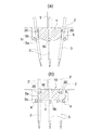
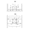
図1に示す実施例1の植栽樹木Tの支持構造は、樹木Tの根鉢1を載置するために地面に形成された植え穴からなる凹部2と、上記凹部2内で根鉢1の周面に沿って、複数(図示例では4本)打ち込まれる丸太製の縦支柱部材3と、各縦支柱部材3に装着されるキャッチ部材20と、各縦支柱部材3に装着されて、前記凹部2内でアンカーとなる根枷部材4を横向きに取り付ける根枷取付具5と、前記縦支柱部材3で根枷取付具5より上方位置に設けられて、上記縦支柱部材3相互を根鉢1に沿って締め付ける締付部材10とからなっている。
The support structure of the planted tree T of Example 1 shown in FIG. 1 includes a
図示例では、縦支柱部材3は、先端を削った丸太が用いられるが、この発明では、井桁形支柱に用いられる切丸太や単管パイプ、その他の根鉢の側面に沿って縦に設置されて根鉢の側面を押圧するものであれば、その素材や支柱構造は特に限定されない。
この縦支柱部材3は、上記凹部2の中で、根鉢1の周面に沿って、略等間隔に打ち込まれる。
打ち込みに際しては、締付後に縦支柱部材3が垂直になるように多少斜めにして打ち込むことが好ましい。
In the illustrated example, the
The
At the time of driving, it is preferable that the
この縦支柱部材3には、中途位置に、予め、根枷取付具5を装着した構成であってもよいが、本実施例では、根枷取付具5は縦支柱部材3と別体となっており、縦支柱部材3が凹部2に打ち込まれた後に、縦支柱部材3に差し込まれて落下し、凹部2の底面に沿って装着される。
The
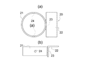
次に、縦支柱部材3には、前記根枷部材4の装着位置の上方で、後述の締付部材10の取付位置より下方となる中間位置で、且つ前記根鉢1の側面に対応する個所に図3に示すキャッチ部材20が取り付けられる。
キャッチ部材20は、本実施例では金属製からなるが、一定の強度を有するものであれば合成樹脂でもよい。
このキャッチ部材20は、前記縦支柱部材3に固定又は拘束される保持部21と、該保持部21に一体に形成されて、締付時に根鉢1の側面に突入可能な突片22とからなっている。
Next, the
The
The
保持部21は、本実施例では縦支柱部材3に外嵌される筒体からなっており、側面に縦支柱部材3に釘を打ち込んでキャッチ部材20を仮止めするための固定用構成部24としての釘孔が形成されている。
縦支柱部材3の断面が円形以外の形状(例えば楕円形、四角形、多角形など)の場合に、保持部21も縦支柱部材3の断面形状に沿った断面形状とすれば、前記固定用構成部を設ける必要はない。
In the present embodiment, the holding
If the
突片22は、保持部21から横方向に突出する片であり、本実施例ではアングル状の片の一方を保持部連結片23として保持部21に溶着しており、他方を突片22としている。
上記突片22は、図示例では平面視で矩形の片からなっており、根鉢1の側面に食い込ませやすくするように先端を幅狭にして刃部としてもよい。
ここで根鉢は、根に土が付着したままのものでも、これを荒縄で根巻きしたものでもよい。
後者の場合には、突片22は根巻きした荒縄と荒縄の間を押し広げ、あるいは一部を切断して根鉢内に食い込ませる。
The protruding
In the illustrated example, the protruding
Here, the root pot may be one in which soil remains attached to the root, or one obtained by rooting this with a rough rope.
In the latter case, the projecting
そして、キャッチ部材20は、突片22の先端が根鉢1の側面の高さ方向の中途位置に向かうようにセットし、保持部21の孔部23から縦支柱部材3に釘を打ち込んで、キャッチ部材20を縦支柱部材3の所定位置に固定する。
ここでキャッチ部材20の縦支柱部材3への固定は、仮止めであってもよい。
Then, the
Here, the
次に、縦支柱部材3には、前記根枷部材4の装着位置の上方に、ワイヤーロープ等を用いて縦支柱部材3相互を緊締するための締付部材10を、その上端が地上に突出しないような位置、図示例では凹部2の上端でほぼグランドラインと一致する位置に装着する。
Next, the
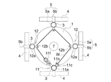
締付部材10は、適宜、公知構成のものを使用しうるが、本実施例の場合、一例として、リング11aの一方に、先端にワイヤーロープWを結ぶためのボルト11bを軸支したブラケット11cを固着し、これと直交する位置に、アーム11dを介して、ワイヤーロープWを牽引して巻き取る逆転防止爪11e付きウインチ11fを装着した第1締付具11と、定滑車となるシーブ12b付きリング12aからなる第2締付具12とを用いている(特許第3860779号参照)。
As the tightening
そこで、図2に一例を示すように、1本の縦支柱部材3に、前記第1締付具11のリング11aを挿入して装着し、残りの縦支柱部材3には、前記第2締付具12のリング12aを挿入して装着する。
そして、第1締付具11のボルト11bに一端を結んだワイヤーロープWを第2締付具12のシーブ12bに通して回し、他端を前記第1締付具11のウインチ11fで巻き取って、縦支柱部材3相互を環状に巻かれたワイヤーロープWの縮小方向に牽引して緊締する。
Therefore, as shown in FIG. 2, the
Then, the wire rope W having one end tied to the
これによりやや斜めに打ち込まれた縦支柱部材3は、根鉢1の側面を押圧するようにほぼ垂直に締め付けられ、同時に、キャッチ部材20の突片22を、根鉢1の側面の高さ方向の中途位置に食い込ませる。
これは、根鉢1が、その高さ方向の上方から中途位置では、根が横方向に延びており、下方では下向きに延びているので、前記突片22を根鉢1に食い込ませても、根鉢1内の根を切断することなく、また根の生育に際して障害となることもない。
この発明で、根鉢1の側面の高さ方向の中途位置とは、根鉢1の上端と下部を除いた中間の領域を全て含むものである。
Accordingly, the
This is because the
In the present invention, the midway position in the height direction of the side surface of the
また、縦支柱部材3は強力に締め付けられるので、キャッチ部材20と縦支柱部材3の間に隙間がある場合にはキャッチ部材20の保持部21が傾斜し、保持部21の角部と縦支柱部材3とが緊締しあってキャッチ部材20を強固に縦支柱部材3に固定することができる。
Moreover, since the vertical support |
上記締付固定の後に、上記第1締付具11や第2締付具12のリング11a、12a上端に突出して地上に出る縦支柱部材を切断する。
この縦支柱部材3の切断片3’は、記根枷取付具5の第2リング5bに差し込まれてアンカーとなる根枷部材5として使用される(図1(b)参照)。
次いで、前記凹部2を埋め戻すことにより、根鉢1や根枷部材4、縦支柱部材3が埋設され、縦支柱部材3は、地下支柱として機能する。
After the tightening and fixing, the vertical strut members protruding from the upper ends of the
The
Next, by refilling the
上記実施例では、縦支柱部材3の上部を切断して根枷部材4として利用したが、予め丸太などの木製の根枷部材4を別に用意しておいてもよい。
また、縦支柱部材3は、上端まで地中に埋設される例を示したが、上部が地上に露出し、又は突出するものであってもよい。
In the said Example, although the upper part of the vertical support |
Moreover, although the vertical support |
上記実施例では、締付部材として本締め用の締付部材のみを用いた場合を例示したが、縦支柱部材3の中途位置に本締め用の締付部材を設け、該本締め用の締付部材より上方位置に仮締め用の締付部材を設けて上下二段に締め付ける構成としてもよい(図示せず)。
この場合、キャッチ部材20は、本締め用の締付部材より下方位置で縦支柱部材3に取り付けられる。
そして締付後には、本締め用締付部材から上方に突出する縦支柱部材3の上部を切断し、その切断片を根枷部材4として使用しうる。
In the above embodiment, the case where only the fastening member for final fastening is used as the fastening member is illustrated. However, a fastening member for final fastening is provided in the middle position of the
In this case, the
After tightening, the upper part of the
上記実施例では、縦支柱部材を4本用いた場合を図示したが、縦支柱部材の数は複数であればよい。
また、締付部材10の構造は本実施例に限定されず、要するに、根鉢の周囲に沿って打ち込まれた複数の縦支柱部材を根鉢に押し付けて締め付ける構造であればよい。
Although the case where four vertical strut members are used is illustrated in the above embodiment, the number of the vertical strut members may be plural.
In addition, the structure of the tightening
図4に示す実施例2のキャッチ部材20は、保持部21が縦支柱部材3よりも大径の場合に、保持部21と縦支柱部材3の隙間を塞ぐための隙間調整手段を備えている。
この隙間調整手段は、保持部21に、前記固定用構成部24の釘孔と離間した位置に孔部を穿設し、該孔部とナットのネジ穴が連通するようにナット25を保持部21の外壁に溶着し、該ナット25にボルト26を螺合した構成からなっている。
The
The gap adjusting means has a hole formed in the holding
従って、ボルト26をナット25のネジに沿って螺進退することで、ボルト26の先端を保持部21で進退させることができ、縦支柱部材3と保持部21の内周面との間に隙間が生じてもボルト26の先端を縦支柱部材3に押圧させることで、保持部21と縦支柱部材3のガタツキを抑えることができる。
その他の構成は、前記実施例1と同様であるので、同一構成には同一符号を付して説明を省略する。
なお、保持部21は上下を反転させることで、突片22の位置を適宜変えることができる。
Therefore, by screwing the
Since other configurations are the same as those of the first embodiment, the same components are denoted by the same reference numerals and description thereof is omitted.
In addition, the holding |
キャッチ部材20の突片22の形状は矩形に限らず任意の形状とすることができる。
図5(a)に示すキャッチ部材20は、突片22が先端に向かって横幅を狭くする平面視で梯形状に形成した場合を示す。梯形に限らず半円形状、半楕円形状、多角形状などであってもよい。
The shape of the projecting
The
また、突片22は、先端を凹凸形状にしてもよい。
図5(b)に示す突片22は、先端を波形形状に形成した場合を示す。
同様に図5(c)ではフォーク形状にした場合を示す。
その他、突片22の形状は、根鉢1に食い込ませても樹木の根の成長を阻害しない形状であればよい。
Moreover, you may make the front-end | tip of the
The protruding
Similarly, FIG. 5C shows a case where the fork shape is used.
In addition, the shape of the projecting
上記実施例では、突片22は1つ設けた場合を例示したが、上下に複数設けてもよい。
図6に示す実施例4のキャッチ部材20は、断面チャンネル状の金具の対向する一対の片をそれぞれ突片22とし、該突片22間をつなぐ片を保持部連結片23とした構成からなっている。
そして、前記保持部連結片23を保持部21の外壁面に溶着してキャッチ部材20としている。
その他の構成は前記実施例と同様であるので、説明を省略する。
In the above-described embodiment, the case where one
The
The holding
Since other configurations are the same as those in the above-described embodiment, description thereof is omitted.
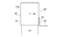
キャッチ部材20は、締付部材と連結され、あるいは一体に形成されるものでもよい。
図7に示すキャッチ部材20’は、締付部材のリング11aを延長して保持部21を一体に形成したもので、1つの筒体50で兼用した構成からなっている。
これによれば、縦支柱部材3へは前記筒体50を装着するだけでよい。
筒体50は上面が塞がれたキャップ状であってもよく、その場合は筒体50の固定用構成部を省略しうる。
The
The
According to this, it is only necessary to attach the
The
また、図示しないが、締付部材のリング11aと保持部21を別々に設けた場合であっても、リング11aと保持部21とをチェーンなどの連結部材で連結しておけば、リング11aを縦支柱部材3に固定することで、保持部21の仮止めや固定用の固定用構成部を省略することができる。
Although not shown, even if the
前記実施例では、保持部21と突片22とは保持部連結片23を保持部21にて溶接して突片22を保持部21に一体に形成した構成を示したが、保持部21に直接に突片22を設けた構成であってもよい。
また、保持部21は縦支柱部材3に固定されるものであればよいので、筒体でなくてもよい。
In the above-described embodiment, the holding
Moreover, since the holding |
図8に示す実施例6のキャッチ部材20は、横断面で円弧状の保持部21’に突片22を一体に形成した構成からなっている。
図示例では保持部21’に略等間隔に釘孔からなる固定用構成部24’が穿設されている。
そして、前記保持部21’を縦支柱部材3の一側(根鉢1方向の側面)に沿わせて配置し、前記固定用構成部24’の釘孔から図中点線で示す釘を縦支柱部材3に打ち込むことで、保持部21’を縦支柱部材3の所定位置に固定することができる。
The
In the illustrated example, a fixing
Then, the holding
図9に示す実施例7のキャッチ部材20は、板状の保持部21”と、該保持部21”の高さ方向の中途位置に一体に設けられて横方向に略水平に突出する突片22とからなっている。
保持部21”は、横断面が湾曲するものでも、扁平なものでもよい。
また、突片22は、保持部21”の上端又は下端に設けられて保持部21”を略直角に折曲げて形成するものでもよい。
The
The holding
The protruding
上記保持部21”には、その内壁面に突片22の突出方向とは逆の内方に突出する釘状の固定用構成部24”を一体に設けている。
これにより、前記釘状の固定用構成部24”を保持部21”を介して縦支柱部材に打ち込むことで突片22を取り付けることができる。
The holding
Accordingly, the protruding
支柱構造は前記実施例に限定されない。
図10には、井桁型支柱構造を示す。
この場合、丸太や単管パイプからなる縦支柱部材3の中途位置にキャッチ部材20が取り付けられ、縦支柱部材3の下部に井桁状に組み合わせたパイプ(図示例では長さ調整可能)や切丸太からなる井桁部材8を連結した構成からなっている。
その他の構成は前記実施例と同様である。
The support structure is not limited to the above embodiment.
FIG. 10 shows a cross beam type strut structure.
In this case, a
Other configurations are the same as those in the above embodiment.
この発明は、上記実施例の各構成を置き換えて用いてもよい。
また、前記実施例に替えて切丸太やパイプを用いた井桁型支柱構造(図10参照)における丸太やパイプの縦支柱部材3に適用してもよい。
その他、要するにこの発明の要旨を変更しない範囲で種々設計変更しうること勿論である。
The present invention may be used by replacing each configuration of the above embodiment.
Further, the present invention may be applied to a log or pipe
In addition, it goes without saying that various design changes can be made without departing from the scope of the present invention.
1 根鉢
2 凹部
3 縦支柱部材
3’ 切断片
4 根枷部材
5 根枷取付具
5a 第1リング
5b 第2リング
10 締付部材
11a リング
11b ボルト
11c ブラケット
11d アーム
11e 逆転防止爪
11f ウインチ
12 第2締付具
12a リング
12b シーブ
20、20’キャッチ部材
21、21’、21”保持部
22 突片
23 保持部連結片
24、24’、24”固定用構成部
T 樹木
W ワイヤーロープ
DESCRIPTION OF
Claims (5)
前記縦支柱部材の締付部材の取付位置より下方で且つ前記根鉢の側面に対応する個所にキャッチ部材を取り付けてなり、
該キャッチ部材が、前記縦支柱部材に固定又は拘束される保持部と、該保持部に一体に形成されて前記締付部材による縦支柱部材の締付時に根鉢の側面に突入する突片とからなることを特徴とする植栽樹木の支持構造。 The upper part of the vertical strut member to be driven along the peripheral surface of the root pot in the recess formed on the ground on which the root pot of the tree is placed is tightened along the side surface of the root pot with the tightening member, and the root with the vertical strut member. In the support structure of the planted tree that is fixed so as to sandwich the side of the pot,
A catch member is attached to a position below the attachment position of the fastening member of the vertical strut member and corresponding to the side surface of the root pot,
A holding part that is fixed or restrained to the vertical strut member, and a projecting piece that is formed integrally with the holding part and enters the side surface of the root pot when the vertical strut member is tightened by the tightening member; A support structure for planted trees characterized by comprising:
キャッチ部材の突片が、前記環状体から横方向に突出し、根鉢の側面に食い込むことができる片からなっていることを特徴とする請求項1又は2に記載の植栽樹木の支持構造。 The holding part of the catch member is composed of an annular body that is externally fitted to the vertical column member,
The planted tree support structure according to claim 1 or 2, wherein the projecting piece of the catch member is a piece that projects laterally from the annular body and can bite into a side surface of the root pot.
キャッチ部材の環状体に、縦支柱部材の所定位置に釘などの固定具で環状体を縦支柱部材に仮止め又は固定するための孔が設けられていることを特徴とする請求項1又は3に記載の植栽樹木の支持構造。 The vertical strut member consists of log piles,
4. A hole for temporarily fixing or fixing the annular body to the vertical strut member with a fixing tool such as a nail at a predetermined position of the vertical strut member in the annular body of the catch member. Support structure of planted tree as described in 2.
縦支柱部材の高さ方向の中途位置に、縦支柱部材に固定又は拘束される保持部と該保持部の一側から一方に突出する突片とからなるキャッチ部材を装着し、
前記縦支柱部材で上記キャッチ部材の上方に締付部材を装着し、
該締付部材で縦支柱部材を締め付ける際に前記キャッチ部材の突片を根鉢の側面に食い込ませて締め付け、上記凹部を埋めて前記根鉢を地中に埋設してなる植栽樹木の支持方法。 The upper part of the vertical strut member to be driven along the peripheral surface of the root pot in the recess formed on the ground on which the root pot of the tree is placed is tightened along the side surface of the root pot with the tightening member, and the root with the vertical strut member. In the method of supporting planted trees that are fixed so as to sandwich the side of the pot,
At a midway position in the height direction of the vertical strut member, a catch member consisting of a holding portion fixed or restrained to the vertical strut member and a projecting piece protruding from one side of the holding portion to one side is mounted.
A fastening member is mounted above the catch member with the vertical strut member,
When tightening the vertical strut member with the tightening member, the projecting piece of the catch member bites into the side of the root pot and tightens, and the planted tree is formed by filling the recess and embedding the root pot in the ground. Method.
Priority Applications (1)
| Application Number | Priority Date | Filing Date | Title |
|---|---|---|---|
| JP2012218826A JP2014068615A (en) | 2012-09-28 | 2012-09-28 | Supporting structure for planted tree and supporting method for the same |
Applications Claiming Priority (1)
| Application Number | Priority Date | Filing Date | Title |
|---|---|---|---|
| JP2012218826A JP2014068615A (en) | 2012-09-28 | 2012-09-28 | Supporting structure for planted tree and supporting method for the same |
Publications (1)
| Publication Number | Publication Date |
|---|---|
| JP2014068615A true JP2014068615A (en) | 2014-04-21 |
Family
ID=50744473
Family Applications (1)
| Application Number | Title | Priority Date | Filing Date |
|---|---|---|---|
| JP2012218826A Pending JP2014068615A (en) | 2012-09-28 | 2012-09-28 | Supporting structure for planted tree and supporting method for the same |
Country Status (1)
| Country | Link |
|---|---|
| JP (1) | JP2014068615A (en) |
Cited By (1)
| Publication number | Priority date | Publication date | Assignee | Title |
|---|---|---|---|---|
| WO2018216286A1 (en) * | 2017-05-26 | 2018-11-29 | 山形開発工業株式会社 | Treefall prevention tool and treefall prevention method |
Citations (8)
| Publication number | Priority date | Publication date | Assignee | Title |
|---|---|---|---|---|
| JPH0657145U (en) * | 1993-01-19 | 1994-08-09 | アンカー産業株式会社 | Supports for planting trees |
| JPH07115857A (en) * | 1993-10-21 | 1995-05-09 | Tsuguhiko Watanabe | Self-supporting and fixing tool for planted tree and method for self-supporting and fixing |
| JPH11239422A (en) * | 1998-02-25 | 1999-09-07 | Nippon Chiko Co Ltd | Fastener for root ball of planting tree |
| JPH11313563A (en) * | 1998-04-30 | 1999-11-16 | Nippon Chiko Co Ltd | Root pot fixing tool for planted tree |
| JP2001054327A (en) * | 1999-08-13 | 2001-02-27 | Tsuguo Nagahata | Structure for supporting planted tree |
| JP2001095399A (en) * | 1999-09-27 | 2001-04-10 | Green & Arts:Kk | Root bowl fixture of planting tree and method for its application |
| JP3860779B2 (en) * | 2002-08-16 | 2006-12-20 | 嗣男 長畑 | Support structure and method for planted trees |
| JP2008109912A (en) * | 2006-10-31 | 2008-05-15 | Toho Leo Co | Tree supporting constructing method, and supporting constructing instrument |
-
2012
- 2012-09-28 JP JP2012218826A patent/JP2014068615A/en active Pending
Patent Citations (8)
| Publication number | Priority date | Publication date | Assignee | Title |
|---|---|---|---|---|
| JPH0657145U (en) * | 1993-01-19 | 1994-08-09 | アンカー産業株式会社 | Supports for planting trees |
| JPH07115857A (en) * | 1993-10-21 | 1995-05-09 | Tsuguhiko Watanabe | Self-supporting and fixing tool for planted tree and method for self-supporting and fixing |
| JPH11239422A (en) * | 1998-02-25 | 1999-09-07 | Nippon Chiko Co Ltd | Fastener for root ball of planting tree |
| JPH11313563A (en) * | 1998-04-30 | 1999-11-16 | Nippon Chiko Co Ltd | Root pot fixing tool for planted tree |
| JP2001054327A (en) * | 1999-08-13 | 2001-02-27 | Tsuguo Nagahata | Structure for supporting planted tree |
| JP2001095399A (en) * | 1999-09-27 | 2001-04-10 | Green & Arts:Kk | Root bowl fixture of planting tree and method for its application |
| JP3860779B2 (en) * | 2002-08-16 | 2006-12-20 | 嗣男 長畑 | Support structure and method for planted trees |
| JP2008109912A (en) * | 2006-10-31 | 2008-05-15 | Toho Leo Co | Tree supporting constructing method, and supporting constructing instrument |
Cited By (1)
| Publication number | Priority date | Publication date | Assignee | Title |
|---|---|---|---|---|
| WO2018216286A1 (en) * | 2017-05-26 | 2018-11-29 | 山形開発工業株式会社 | Treefall prevention tool and treefall prevention method |
Similar Documents
| Publication | Publication Date | Title |
|---|---|---|
| JP6389271B2 (en) | Cradle clamp bracket assembly | |
| US9957685B2 (en) | Method and apparatus for portable stake mounting | |
| US9820446B2 (en) | Line attachment mechanism and systems and methods for using the same | |
| JP2014068615A (en) | Supporting structure for planted tree and supporting method for the same | |
| JP4796935B2 (en) | Tree support construction method and support construction tools | |
| KR101036395B1 (en) | The tree of branch allurement equipment | |
| JP3860779B2 (en) | Support structure and method for planted trees | |
| JP3364452B2 (en) | Method for supporting planted tree and its structure | |
| KR101151443B1 (en) | Device Against Wind Pressure On The Green Roof System | |
| EP3028604B1 (en) | Groove for passing a link in order to secure the attachment of a protective cover | |
| KR200441171Y1 (en) | The supporting device for a tree | |
| CA2603953C (en) | Bracket | |
| JP2004065058A (en) | Fixedly supporting tool for root ball of tree | |
| JP2018057289A (en) | Trapping trigger device | |
| KR101044516B1 (en) | Band for supporting tree | |
| JP3145458B2 (en) | How to plant trees | |
| TWI450683B (en) | Support construction method and device for tree | |
| KR101179688B1 (en) | Device Against Wind Pressure On The Green Roof System | |
| KR200429591Y1 (en) | A supporting bar for tree | |
| JPH1014415A (en) | Planting apparatus | |
| KR102642429B1 (en) | Growing tree-friendly bolt | |
| KR200485322Y1 (en) | Support tool for Fruit tree | |
| JP2008161136A (en) | Support construction method and support construction tool for tree | |
| GB2537980A (en) | Gripping arrangement | |
| AU2004202761B2 (en) | A Ground Anchor |
Legal Events
| Date | Code | Title | Description |
|---|---|---|---|
| A621 | Written request for application examination |
Free format text: JAPANESE INTERMEDIATE CODE: A621 Effective date: 20140905 |
|
| A977 | Report on retrieval |
Free format text: JAPANESE INTERMEDIATE CODE: A971007 Effective date: 20150723 |
|
| A131 | Notification of reasons for refusal |
Free format text: JAPANESE INTERMEDIATE CODE: A131 Effective date: 20150805 |
|
| A521 | Written amendment |
Free format text: JAPANESE INTERMEDIATE CODE: A523 Effective date: 20151005 |
|
| A02 | Decision of refusal |
Free format text: JAPANESE INTERMEDIATE CODE: A02 Effective date: 20160330 |