JP2014055152A - Improved fluorination reactor - Google Patents
Improved fluorination reactor Download PDFInfo
- Publication number
- JP2014055152A JP2014055152A JP2013229238A JP2013229238A JP2014055152A JP 2014055152 A JP2014055152 A JP 2014055152A JP 2013229238 A JP2013229238 A JP 2013229238A JP 2013229238 A JP2013229238 A JP 2013229238A JP 2014055152 A JP2014055152 A JP 2014055152A
- Authority
- JP
- Japan
- Prior art keywords
- reaction
- reactor
- fluoride
- organic compound
- composition
- Prior art date
- Legal status (The legal status is an assumption and is not a legal conclusion. Google has not performed a legal analysis and makes no representation as to the accuracy of the status listed.)
- Pending
Links
Images
Classifications
-
- B—PERFORMING OPERATIONS; TRANSPORTING
- B01—PHYSICAL OR CHEMICAL PROCESSES OR APPARATUS IN GENERAL
- B01J—CHEMICAL OR PHYSICAL PROCESSES, e.g. CATALYSIS OR COLLOID CHEMISTRY; THEIR RELEVANT APPARATUS
- B01J8/00—Chemical or physical processes in general, conducted in the presence of fluids and solid particles; Apparatus for such processes
- B01J8/02—Chemical or physical processes in general, conducted in the presence of fluids and solid particles; Apparatus for such processes with stationary particles, e.g. in fixed beds
- B01J8/0242—Chemical or physical processes in general, conducted in the presence of fluids and solid particles; Apparatus for such processes with stationary particles, e.g. in fixed beds the fluid flow within the bed being predominantly vertical
- B01J8/025—Chemical or physical processes in general, conducted in the presence of fluids and solid particles; Apparatus for such processes with stationary particles, e.g. in fixed beds the fluid flow within the bed being predominantly vertical in a cylindrical shaped bed
-
- C—CHEMISTRY; METALLURGY
- C07—ORGANIC CHEMISTRY
- C07C—ACYCLIC OR CARBOCYCLIC COMPOUNDS
- C07C17/00—Preparation of halogenated hydrocarbons
- C07C17/013—Preparation of halogenated hydrocarbons by addition of halogens
-
- B—PERFORMING OPERATIONS; TRANSPORTING
- B01—PHYSICAL OR CHEMICAL PROCESSES OR APPARATUS IN GENERAL
- B01J—CHEMICAL OR PHYSICAL PROCESSES, e.g. CATALYSIS OR COLLOID CHEMISTRY; THEIR RELEVANT APPARATUS
- B01J8/00—Chemical or physical processes in general, conducted in the presence of fluids and solid particles; Apparatus for such processes
- B01J8/02—Chemical or physical processes in general, conducted in the presence of fluids and solid particles; Apparatus for such processes with stationary particles, e.g. in fixed beds
- B01J8/04—Chemical or physical processes in general, conducted in the presence of fluids and solid particles; Apparatus for such processes with stationary particles, e.g. in fixed beds the fluid passing successively through two or more beds
-
- C—CHEMISTRY; METALLURGY
- C07—ORGANIC CHEMISTRY
- C07B—GENERAL METHODS OF ORGANIC CHEMISTRY; APPARATUS THEREFOR
- C07B39/00—Halogenation
-
- C—CHEMISTRY; METALLURGY
- C07—ORGANIC CHEMISTRY
- C07C—ACYCLIC OR CARBOCYCLIC COMPOUNDS
- C07C17/00—Preparation of halogenated hydrocarbons
- C07C17/07—Preparation of halogenated hydrocarbons by addition of hydrogen halides
-
- C—CHEMISTRY; METALLURGY
- C07—ORGANIC CHEMISTRY
- C07C—ACYCLIC OR CARBOCYCLIC COMPOUNDS
- C07C17/00—Preparation of halogenated hydrocarbons
- C07C17/093—Preparation of halogenated hydrocarbons by replacement by halogens
- C07C17/10—Preparation of halogenated hydrocarbons by replacement by halogens of hydrogen atoms
-
- B—PERFORMING OPERATIONS; TRANSPORTING
- B01—PHYSICAL OR CHEMICAL PROCESSES OR APPARATUS IN GENERAL
- B01J—CHEMICAL OR PHYSICAL PROCESSES, e.g. CATALYSIS OR COLLOID CHEMISTRY; THEIR RELEVANT APPARATUS
- B01J2208/00—Processes carried out in the presence of solid particles; Reactors therefor
- B01J2208/00008—Controlling the process
- B01J2208/00017—Controlling the temperature
- B01J2208/0053—Controlling multiple zones along the direction of flow, e.g. pre-heating and after-cooling
-
- B—PERFORMING OPERATIONS; TRANSPORTING
- B01—PHYSICAL OR CHEMICAL PROCESSES OR APPARATUS IN GENERAL
- B01J—CHEMICAL OR PHYSICAL PROCESSES, e.g. CATALYSIS OR COLLOID CHEMISTRY; THEIR RELEVANT APPARATUS
- B01J2208/00—Processes carried out in the presence of solid particles; Reactors therefor
- B01J2208/00743—Feeding or discharging of solids
- B01J2208/00752—Feeding
-
- B—PERFORMING OPERATIONS; TRANSPORTING
- B01—PHYSICAL OR CHEMICAL PROCESSES OR APPARATUS IN GENERAL
- B01J—CHEMICAL OR PHYSICAL PROCESSES, e.g. CATALYSIS OR COLLOID CHEMISTRY; THEIR RELEVANT APPARATUS
- B01J2208/00—Processes carried out in the presence of solid particles; Reactors therefor
- B01J2208/00743—Feeding or discharging of solids
- B01J2208/00761—Discharging
-
- B—PERFORMING OPERATIONS; TRANSPORTING
- B01—PHYSICAL OR CHEMICAL PROCESSES OR APPARATUS IN GENERAL
- B01J—CHEMICAL OR PHYSICAL PROCESSES, e.g. CATALYSIS OR COLLOID CHEMISTRY; THEIR RELEVANT APPARATUS
- B01J2208/00—Processes carried out in the presence of solid particles; Reactors therefor
- B01J2208/00796—Details of the reactor or of the particulate material
- B01J2208/00946—Features relating to the reactants or products
- B01J2208/00955—Sampling of the particulate material, the reactants or the products
- B01J2208/00973—Products
-
- B—PERFORMING OPERATIONS; TRANSPORTING
- B01—PHYSICAL OR CHEMICAL PROCESSES OR APPARATUS IN GENERAL
- B01J—CHEMICAL OR PHYSICAL PROCESSES, e.g. CATALYSIS OR COLLOID CHEMISTRY; THEIR RELEVANT APPARATUS
- B01J2219/00—Chemical, physical or physico-chemical processes in general; Their relevant apparatus
- B01J2219/00002—Chemical plants
- B01J2219/00027—Process aspects
- B01J2219/00038—Processes in parallel
-
- B—PERFORMING OPERATIONS; TRANSPORTING
- B01—PHYSICAL OR CHEMICAL PROCESSES OR APPARATUS IN GENERAL
- B01J—CHEMICAL OR PHYSICAL PROCESSES, e.g. CATALYSIS OR COLLOID CHEMISTRY; THEIR RELEVANT APPARATUS
- B01J2219/00—Chemical, physical or physico-chemical processes in general; Their relevant apparatus
- B01J2219/00049—Controlling or regulating processes
- B01J2219/00191—Control algorithm
- B01J2219/00193—Sensing a parameter
- B01J2219/00195—Sensing a parameter of the reaction system
- B01J2219/00202—Sensing a parameter of the reaction system at the reactor outlet
-
- B—PERFORMING OPERATIONS; TRANSPORTING
- B01—PHYSICAL OR CHEMICAL PROCESSES OR APPARATUS IN GENERAL
- B01J—CHEMICAL OR PHYSICAL PROCESSES, e.g. CATALYSIS OR COLLOID CHEMISTRY; THEIR RELEVANT APPARATUS
- B01J2219/00—Chemical, physical or physico-chemical processes in general; Their relevant apparatus
- B01J2219/00049—Controlling or regulating processes
- B01J2219/00191—Control algorithm
- B01J2219/00211—Control algorithm comparing a sensed parameter with a pre-set value
- B01J2219/00213—Fixed parameter value
-
- B—PERFORMING OPERATIONS; TRANSPORTING
- B01—PHYSICAL OR CHEMICAL PROCESSES OR APPARATUS IN GENERAL
- B01J—CHEMICAL OR PHYSICAL PROCESSES, e.g. CATALYSIS OR COLLOID CHEMISTRY; THEIR RELEVANT APPARATUS
- B01J2219/00—Chemical, physical or physico-chemical processes in general; Their relevant apparatus
- B01J2219/00049—Controlling or regulating processes
- B01J2219/00191—Control algorithm
- B01J2219/00222—Control algorithm taking actions
- B01J2219/00227—Control algorithm taking actions modifying the operating conditions
- B01J2219/00229—Control algorithm taking actions modifying the operating conditions of the reaction system
- B01J2219/00231—Control algorithm taking actions modifying the operating conditions of the reaction system at the reactor inlet
-
- Y—GENERAL TAGGING OF NEW TECHNOLOGICAL DEVELOPMENTS; GENERAL TAGGING OF CROSS-SECTIONAL TECHNOLOGIES SPANNING OVER SEVERAL SECTIONS OF THE IPC; TECHNICAL SUBJECTS COVERED BY FORMER USPC CROSS-REFERENCE ART COLLECTIONS [XRACs] AND DIGESTS
- Y02—TECHNOLOGIES OR APPLICATIONS FOR MITIGATION OR ADAPTATION AGAINST CLIMATE CHANGE
- Y02P—CLIMATE CHANGE MITIGATION TECHNOLOGIES IN THE PRODUCTION OR PROCESSING OF GOODS
- Y02P20/00—Technologies relating to chemical industry
- Y02P20/50—Improvements relating to the production of bulk chemicals
- Y02P20/582—Recycling of unreacted starting or intermediate materials
Landscapes
- Chemical & Material Sciences (AREA)
- Organic Chemistry (AREA)
- Chemical Kinetics & Catalysis (AREA)
- Physics & Mathematics (AREA)
- Fluid Mechanics (AREA)
- Organic Low-Molecular-Weight Compounds And Preparation Thereof (AREA)
- Solid-Sorbent Or Filter-Aiding Compositions (AREA)
- Separation Of Gases By Adsorption (AREA)
Abstract
【課題】元素状フッ素と、有機化合物との反応において、生成するHFの量を低減させる反応器の提供。
【解決手段】フッ素化される有機化合物が元素状フッ素と接触させられ、HFが副生成物として生成されるフッ素化反応において、この元素状フッ素は、HFまたは別の水素含有副生成物の量が低減されるかまたは無くされるように、フッ化物吸着組成物の存在下で有機化合物と接触させられる。フッ素化反応用の反応器の実施形態もまた、開示される。該フッ化物吸着組成物がアルカリハロゲン化物及びアルカリ土類ハロゲン化物からなる群から選択された化合物を含む。
【選択図】なしTo provide a reactor capable of reducing the amount of HF produced in the reaction of elemental fluorine with an organic compound.
In a fluorination reaction in which an organic compound to be fluorinated is brought into contact with elemental fluorine and HF is produced as a byproduct, this elemental fluorine is present in the amount of HF or another hydrogen-containing byproduct. Is contacted with the organic compound in the presence of the fluoride-adsorbing composition so that is reduced or eliminated. An embodiment of a reactor for the fluorination reaction is also disclosed. The fluoride adsorbing composition comprises a compound selected from the group consisting of alkali halides and alkaline earth halides.
[Selection figure] None
Description
発明の背景
本発明は、HFが副生成物として形成される、元素状フッ素を用いたフッ素化反応の改
善に関する。特に、本発明は、HF吸着組成物の存在下で反応物を接触させ、その結果、
形成されるいかなるHFも反応系から除去され、他の望ましくない水素含有副生成物の形
成を防止する、フッ素化反応に関する。また、本発明はHF吸着組成物が充填された反応
域を有する、改善されたフッ素化反応器に関する。
The present invention relates to an improvement in fluorination reactions using elemental fluorine in which HF is formed as a byproduct. In particular, the present invention contacts the reactants in the presence of the HF adsorbent composition, so that
It relates to a fluorination reaction in which any HF formed is removed from the reaction system and prevents the formation of other undesirable hydrogen-containing byproducts. The invention also relates to an improved fluorination reactor having a reaction zone filled with an HF adsorption composition.
背景技術
元素状フッ素(F2)と、多くの材料、特に有機化合物との反応は、かなり発熱性であ
ることができ、CF4が、通常熱力学的に優先される反応生成物である。さまざまな反応
器のデザインが、このような反応を制御するために提案されてきたが、フッ素化は、CF
4を高収量で生成することができない状態で停滞させられたままである。例えば、米国特
許第4377715号には、制御された状態でフッ素と有機物とを接触させるために、多
孔質の管状反応器を使用することが記載されている。米国特許第5675046号には、
ペルフルオロカーボンを生成するために、2つの反応域システムを使用することが記載さ
れている。このような反応器は、反応を制御するように設計されている。このような反応
器はまた、熱力学的に有利なCF4の形成を最小にするように通常設計される。
Background Art The reaction of elemental fluorine (F 2 ) with many materials, especially organic compounds, can be quite exothermic and CF 4 is usually the thermodynamically preferred reaction product. Various reactor designs have been proposed to control such reactions, but fluorination is a CF
4 remains stuck in a state where it cannot be produced in high yield. For example, US Pat. No. 4,377,715 describes the use of a porous tubular reactor to contact fluorine and organics in a controlled manner. US Pat. No. 5,675,046 includes
The use of two reaction zone systems has been described to produce perfluorocarbons. Such reactors are designed to control the reaction. Such reactors are also typically designed to minimize the formation of thermodynamically favorable CF 4.
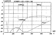
図1は、C2HF5が1モルおよびF2が1モルの初期組成物を基準にした反応、C2
HF5+F2=C2F6+HFの、温度の関数として計算された熱力学的平衡を示す。図
1は、実際上熱力学が、この反応は定量的であり、C2HF5の1モルとF2の1モルと
が、本質的にC2F6を1モルおよびHFを1モル生じさせると予測することを示す。図
1は、未反応F2およびC2HF5の量は、0から約500℃の温度範囲にわたって、約
10−10モル未満のはずであることを示す。
FIG. 1 shows the reaction based on an initial composition with 1 mole of C 2 HF 5 and 1 mole of F 2 , C 2
HF for 5 + F 2 = C 2 F 6 + HF, shows the calculated thermodynamic equilibrium as a function of temperature. FIG. 1 shows that in practice thermodynamics, this reaction is quantitative, with 1 mole of C 2 HF 5 and 1 mole of F 2 yielding essentially 1 mole of C 2 F 6 and 1 mole of HF. Indicates that it will be predicted. FIG. 1 shows that the amount of unreacted F 2 and C 2 HF 5 should be less than about 10 −10 moles over a temperature range of 0 to about 500 ° C.
熱力学計算は、所与の反応が生じるか否か、および最大収量はいくつかを予測するのに
非常に有効である。しかし、予測された結果を実験室において達成することは、常に可能
というわけではない。1つの理由は、熱力学は、反応が平衡に到達するのに要する可能性
のある時間の長さを指示しないことである。別の理由は、安定な化合物が計算から漏れた
場合、間違った結果が得られる可能性があることである。
Thermodynamic calculations are very useful in predicting whether a given reaction occurs and the maximum yield is some. However, achieving the predicted results in the laboratory is not always possible. One reason is that thermodynamics do not dictate the length of time that a reaction may take to reach equilibrium. Another reason is that incorrect results can be obtained if a stable compound is left out of the calculation.
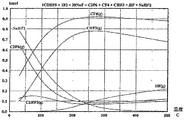
例えば、C2HF5とF2が実験室で反応させられた場合、いくらかのCF4およびC
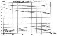
H3Fが共生成物として観察される。図3は、C2HF5が1モルおよびF2が1モルの
初期組成物を基準にした反応、C2HF5+F2=C2F6+HF+CF4+CHF3の
、温度の関数として計算された熱力学的平衡を示す。図3は、CF4は研究した温度範囲
にわたって熱力学的に有利な生成物であるが、生成された量は、温度が上昇するにつれて
減少しなければならないことを示す。CF4は、極めて安定であるために生成物の大半を
占める。C2HF5とF2との反応が、計算した熱力学的平衡とは異なり、C2F6の大
部分を生成するという事実は、速度因子が活動するようになり、実験室の反応が熱力学的
平衡に到達しないことを示す。
For example, if C 2 HF 5 and F 2 are reacted in the laboratory, some CF 4 and C
H 3 F is observed as a coproduct. FIG. 3 is calculated as a function of temperature for a reaction based on an initial composition of 1 mole C 2 HF 5 and 1 mole F 2 , C 2 HF 5 + F 2 = C 2 F 6 + HF + CF 4 + CHF 3. Shows thermodynamic equilibrium. FIG. 3 shows that although CF 4 is a thermodynamically favorable product over the temperature range studied, the amount produced must decrease as the temperature increases. CF 4 accounts for the majority of the product because it is very stable. The fact that the reaction of C 2 HF 5 and F 2 , unlike the calculated thermodynamic equilibrium, produces the majority of C 2 F 6 is due to the fact that the rate factor becomes active and the laboratory reaction Indicates that thermodynamic equilibrium is not reached.
金属フッ化物は、HFを吸収するのに長い間使用されてきた。例えば、Froning
ら、Indus.Eng.Chem.,39(3),275頁(1947年)には、フッ
素からHFを除去するためにフッ化ナトリウムのペレットを使用することが記載されてい
る。この論文は、NaHF2の上のHFの蒸気圧は、約278℃においてHFの蒸気圧が
1気圧になるまで、温度が上昇するにつれて上昇することを示す。したがって、278℃
を超える温度においては、フッ化ナトリウム/フッ化水素ナトリウムはガス流れからHF
を除去するのに有効ではない。フッ化ナトリウムもまた、米国特許第4377715号に
おけるように、生成物の収集およびその後の分析を簡単にするために、分析に先立って反
応器流出物からHFを除去するのに使用されてきた。
Metal fluorides have long been used to absorb HF. For example, Froning
Et al., Indus. Eng. Chem. 39 (3), 275 (1947) describe the use of pellets of sodium fluoride to remove HF from fluorine. This paper shows that the vapor pressure of HF over NaHF 2 increases with increasing temperature until the vapor pressure of HF is about 1 atmosphere at 278 ° C. Therefore, 278 ° C
At temperatures above 50 ° F, sodium fluoride / sodium hydrogen fluoride is
Is not effective in removing. Sodium fluoride has also been used to remove HF from the reactor effluent prior to analysis to simplify product collection and subsequent analysis, as in US Pat. No. 4,377,715.
米国特許第4859747号には、より過酷なフッ素化条件(より高いフッ素濃度およ
びフッ素送達(delivery)のより速い速度)を用いることを可能にする、固体お
よび液体エーテルの直接フッ素化におけるフッ化ナトリウムの使用が記載されている。こ
の特許には、フッ化ナトリウムを使用してHFを捕捉し、HFとエーテルの酸素結合との
反応を防止することが開示されている。この特許は、このエーテルの用途に全く特有のも
のであり、フッ化ナトリウムの化学量論的量を使用することと、バッチ式で反応を行わせ
ることと、出発材料を、フッ素化が完了しないうちに反応器から運び去られないように維
持することの重要性とを、開示している。しかし、金属フッ化物を使用して、反応生成物
の熱力学的に決定される分布を制御することは知られていない。
US Pat. No. 4,859,747 describes sodium fluoride in the direct fluorination of solid and liquid ethers, which allows the use of more severe fluorination conditions (higher fluorine concentrations and faster rates of fluorine delivery). The use of is described. This patent discloses the use of sodium fluoride to capture HF and prevent reaction of HF with the ether oxygen bonds. This patent is quite specific for this ether application, using a stoichiometric amount of sodium fluoride, allowing the reaction to occur batchwise, and the starting material not completing the fluorination The importance of keeping it from being carried away from the reactor is disclosed. However, it is not known to use metal fluoride to control the thermodynamically determined distribution of the reaction product.
発明の概要
フッ素化反応器に、フッ化ナトリウムなどのフッ化物吸着剤を充填することにより、水
素含有副生成物が生じ得る反応の収量を増加させることが、今回わかった。反応からHF
を除去することにより、HFが、フッ素化される化合物と反応して不要な水素含有副生成
物を形成することを防止する。
Summary of the Invention It has now been found that filling a fluorination reactor with a fluoride adsorbent, such as sodium fluoride, increases the yield of the reaction that can produce hydrogen-containing by-products. HF from reaction
Is removed to prevent HF from reacting with the compound to be fluorinated to form unwanted hydrogen-containing by-products.
したがって、本発明の一態様によれば、フッ素化される有機化合物が元素状フッ素と接
触させられ、HFが副生成物として生成されるフッ素化反応が提供され、この元素状フッ
素は、HFまたは別の水素含有副生成物の量が低減されるかまたは無くされるように、フ
ッ化物吸着組成物の存在下で有機化合物と接触させられる。本発明のこの態様の一実施形
態によれば、有機化合物はフルオロ炭化水素である。
Thus, according to one aspect of the present invention, there is provided a fluorination reaction in which an organic compound to be fluorinated is brought into contact with elemental fluorine and HF is produced as a byproduct, the elemental fluorine being HF or Contacted with the organic compound in the presence of the fluoride-adsorbing composition so that the amount of another hydrogen-containing byproduct is reduced or eliminated. According to one embodiment of this aspect of the invention, the organic compound is a fluorohydrocarbon.
本発明のこの態様の別の実施形態は、フッ化物吸着組成物が、アルカリ金属ハロゲン化
物およびアルカリ土類ハロゲン化物およびフッ化物吸着ポリマーから選択された1種また
は複数種の化合物を含有する反応である。好ましい実施形態において、フッ化物吸着組成
物はフッ化ナトリウムを含有する。
Another embodiment of this aspect of the invention is a reaction wherein the fluoride adsorption composition contains one or more compounds selected from alkali metal halides and alkaline earth halides and fluoride adsorption polymers. is there. In a preferred embodiment, the fluoride adsorption composition contains sodium fluoride.
本発明のフッ素化反応は、フッ素化反応器の反応域にフッ化物吸着組成物を充填するこ
とにより実施される。したがって、本発明の別の態様によれば、反応域、フッ素化される
有機化合物を反応域へ供給するための入口、元素状フッ素を反応域へ供給して有機化合物
と反応させ、有機化合物をフッ素化するための入口、およびフッ素化された反応生成物を
回収するための出口を有し、反応域が、有機化合物と元素状フッ素との反応の副生成物と
して生成されたいかなるHFも除去するために、フッ化物吸着組成物を含有する、フッ素
化反応器が提供される。
The fluorination reaction of the present invention is carried out by filling the reaction zone of the fluorination reactor with the fluoride adsorption composition. Therefore, according to another aspect of the present invention, the reaction zone, the inlet for supplying the fluorinated organic compound to the reaction zone, the elemental fluorine supplied to the reaction zone to react with the organic compound, Has an inlet for fluorination and an outlet for recovering the fluorinated reaction product, and the reaction zone removes any HF produced as a byproduct of the reaction of organic compounds with elemental fluorine To do so, a fluorination reactor is provided that contains a fluoride adsorption composition.
本発明のこの態様の一実施形態によれば、反応器は気相反応器であり、フッ化物吸着組
成物は固相材料である。本発明のこの態様の別の実施形態によれば、フッ化物吸着組成物
を補給するための手段が提供される。好ましい実施形態によれば、補給手段は、HFが脱
着されるようにフッ化物吸着組成物を加熱するための手段と、脱着されたHFが出口を通
って反応器から押し流されるように不活性ガス流れを供給するための入口とを含む。
According to one embodiment of this aspect of the invention, the reactor is a gas phase reactor and the fluoride adsorbing composition is a solid phase material. According to another embodiment of this aspect of the invention, means are provided for replenishing the fluoride-adsorbing composition. According to a preferred embodiment, the replenishment means comprises means for heating the fluoride adsorbing composition such that HF is desorbed and an inert gas such that the desorbed HF is flushed from the reactor through the outlet. And an inlet for supplying a flow.
本発明の前述およびその他の目的、特徴および利点は、添付図と併用される、以下に記
載の好ましい実施形態の詳細な説明から一層容易に明らかになる。
The foregoing and other objects, features and advantages of the present invention will become more readily apparent from the detailed description of the preferred embodiments set forth below, taken in conjunction with the accompanying drawings.
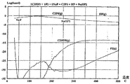
好ましい実施形態の詳細な説明
図4は、フッ化ナトリウムの添加が、どのように図3の反応の平衡:
1C2HF5+1F2+30NaF→C2F6+HF+CF4+CHF3+NaHF2
を変化させるかを示す。
Detailed Description of the Preferred Embodiments FIG. 4 shows how the addition of sodium fluoride balances the reaction of FIG.
1C 2 HF 5 + 1F 2 + 30NaF → C 2 F 6 + HF + CF 4 + CHF 3 + NaHF 2
Indicates whether to change
例えば、100℃(NaFなし)においては、C2F6が0.05kモル未満形成され
、最初にNaFが30kモル存在する、同一の条件下においては、C2F6が約0.3k
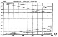
モル形成される。図5は、平衡組成物が、同一反応の100℃においてNaFの量が変化
すると共に、どのように変化するかということ、および約280℃超においては、図3と
図4との間に差がないこと、すなわち、NaF/NaHF2の比が平衡に影響しないこと
を示す。蒸気流れからHFを除去することにより、水素含有副生成物は形成しにくくなる
。このことは、約280℃未満の温度において、図4が図3とどのように異なるかという
ことのなかに、明瞭に示されている。
For example, at 100 ° C. (without NaF), less than 0.05 kmol of C 2 F 6 is formed, and under the same conditions where 30 kmol of NaF is initially present, C 2 F 6 is about 0.3 kmol.
Mole formed. FIG. 5 shows how the equilibrium composition changes as the amount of NaF changes at 100 ° C. in the same reaction, and between about 3 and 4 above about 280 ° C. That is, the ratio of NaF / NaHF 2 does not affect the equilibrium. By removing HF from the vapor stream, hydrogen-containing byproducts are less likely to form. This is clearly shown in how FIG. 4 differs from FIG. 3 at temperatures below about 280 ° C.
これは、気相および液相フッ素化に対する実用的な意味を有し、さまざまな方法で実施
され得る。フッ素化反応器の1つまたは複数の反応域は、フッ素化される有機化合物およ
び使用される元素状フッ素のモル量に対して、化学量論的過剰量のフッ化物吸着組成物に
よって充填される。化学量論的過剰は、それぞれの反応域を部分的にまたは完全に満たす
ことができる。吸着組成物は、固相の場合、それぞれの反応域を通じて反応物および反応
生成物の流れをそれほど妨害することなく、反応混合物と接触するのに利用することがで
きる表面積を最大化するように選択された粒径を有さなければならない。吸着組成物が交
換および/または再生されなければならない頻度を減らすことになるので、吸着組成物の
事実上の最大量が好ましい。これらのパラメータは、必要以上の実験を行うことなく、当
業者により容易に求められ得る。
This has practical implications for gas phase and liquid phase fluorination and can be implemented in a variety of ways. One or more reaction zones of the fluorination reactor are filled with a stoichiometric excess of fluoride adsorption composition relative to the molar amount of organic compound to be fluorinated and the elemental fluorine used. . The stoichiometric excess can partially or completely fill each reaction zone. The adsorbent composition is selected to maximize the surface area that can be utilized to contact the reaction mixture in the solid phase without significantly disturbing the flow of reactants and reaction products through the respective reaction zone. Must have a reduced particle size. A practical maximum amount of adsorbent composition is preferred because it reduces the frequency with which the adsorbent composition must be replaced and / or regenerated. These parameters can be easily determined by one skilled in the art without undue experimentation.
単一反応器を使用し得る。HFまたはその他の水素含有副生成物が増大することが検出
された場合、供給原料を停止することができ、例えば吸着組成物がフッ化ナトリウムを含
有する場合、フッ化ナトリウム/フッ化水素ナトリウムの混合物を、交換または再生する
ことができる。または、並列の2つ以上の反応器を使用して、HFまたはその他の水素含
有副生成物が増大することが検出された場合、供給原料を、新しいフッ化ナトリウムを含
有する別の反応器へ切り替え、同時に第1反応器中の使用済みのフッ化ナトリウム/フッ
化水素ナトリウムの混合物を再生することができる。
A single reactor can be used. If an increase in HF or other hydrogen-containing by-product is detected, the feed can be shut down, eg, if the adsorption composition contains sodium fluoride, sodium fluoride / sodium hydrogen fluoride The mixture can be exchanged or regenerated. Alternatively, if two or more reactors in parallel are used to detect an increase in HF or other hydrogen-containing by-products, the feed is transferred to another reactor containing fresh sodium fluoride. At the same time, the spent sodium fluoride / sodium hydrogen fluoride mixture in the first reactor can be regenerated.
検出手段は、スプリッタなどの反応器出口に連通している試料収集手段を含み、この試
料収集手段は、ガスクロマトグラフィーなどの分離手段に連通しており、この分離手段は
、分離された画分を同定するための手段、通常、質量分光光度計または赤外分光光度計な
どの分光光度計に連通している。分離手段は、存在するそれぞれの画分の量を、好ましく
は定量的に求める。化学の精度に応じて、材料を画分に分割するスプリッタを使用する必
要がない場合がある。例えば、いくつかの混合物は、赤外分光法により、直接分析され得
る。また、種々の反応が、種々の分析技法を必要とする場合もある。GCまたはIRのみ
で、ある場合は十分である可能性があるが、一方、別の場合にはGC−MSが必要になる
可能性がある。このことは、必要以上の実験をすることなく、当業者が容易に決めること
ができる。1つまたは複数の反応器もまた、有機化合物および元素状フッ素の反応してい
ない量を分離し、これらのそれぞれの反応器の入口に戻すための手段を含むことができる
。
The detection means includes sample collection means communicating with the outlet of the reactor such as a splitter, and the sample collection means communicates with separation means such as gas chromatography. Is generally in communication with a spectrophotometer such as a mass spectrophotometer or an infrared spectrophotometer. The separating means preferably determines the amount of each fraction present, preferably quantitatively. Depending on the accuracy of the chemistry, it may not be necessary to use a splitter that splits the material into fractions. For example, some mixtures can be analyzed directly by infrared spectroscopy. Different reactions may also require different analytical techniques. Only GC or IR may be sufficient in some cases, while in other cases GC-MS may be required. This can be easily determined by those skilled in the art without undue experimentation. The reactor or reactors can also include means for separating unreacted amounts of organic compound and elemental fluorine and returning them to the respective reactor inlets.
フッ化ナトリウム/フッ化水素ナトリウムなどの吸着組成物の一部が、周期的にまたは
連続的に除去され、新しい材料と交換される、別の反応器デザインもまた可能である。フ
ッ化ナトリウムまたはフッ化水素ナトリウムなどの吸着剤の完全な再生は、不活性ガスを
流しながら、約280℃または280℃超、好ましくは約280℃から約300℃の間で
混合物を加熱して、不活性ガスにより押し流されたHFを脱着し、NaFを再形成するこ
とにより実施される。280〜300℃における完全な再生が好ましいが、より低い温度
において部分的な再生を行うことができる。フッ化ナトリウムに加えて、他の固体フッ化
物吸着剤も使用することができ、これらの例には、アルカリ金属ハロゲン化物、アルカリ
土類ハロゲン化物などが含まれる。
Alternative reactor designs are also possible in which a portion of the adsorbent composition such as sodium fluoride / sodium hydrogen fluoride is removed periodically or continuously and replaced with fresh material. Complete regeneration of the adsorbent, such as sodium fluoride or sodium hydrogen fluoride, can be accomplished by heating the mixture at about 280 ° C. or above 280 ° C., preferably between about 280 ° C. and about 300 ° C., while flowing an inert gas. , By desorbing HF swept by inert gas and re-forming NaF. Although complete regeneration at 280-300 ° C is preferred, partial regeneration can be performed at lower temperatures. In addition to sodium fluoride, other solid fluoride adsorbents can be used, examples of which include alkali metal halides, alkaline earth halides, and the like.
本発明の方法によりフッ素化され得る有機化合物には、炭化水素ならびにフッ素、塩素
、臭素およびヨウ素から選択された同一のまたは異なるハロゲン原子を含有するハロ炭化
水素が含まれる。本発明の方法は、フルオロ炭化水素を使用して例示される。有機化合物
は脂肪族または芳香族であり得る。脂肪族有機化合物は、飽和または不飽和および直鎖ま
たは分岐であり得る。脂肪族および芳香族化合物は、フッ素化反応条件下において元素状
フッ素に対して不活性である、1種または複数種の非ハロゲン置換基によって置換されて
いてよく、または元素状フッ素と反応して所定の反応生成物を生成するように選択される
。
Organic compounds that can be fluorinated by the process of the present invention include hydrocarbons and halohydrocarbons containing the same or different halogen atoms selected from fluorine, chlorine, bromine and iodine. The process of the present invention is illustrated using a fluorohydrocarbon. The organic compound can be aliphatic or aromatic. Aliphatic organic compounds can be saturated or unsaturated and linear or branched. Aliphatic and aromatic compounds may be substituted by one or more non-halogen substituents that are inert to elemental fluorine under fluorination reaction conditions, or react with elemental fluorine. It is selected to produce a given reaction product.
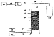
本発明によるフッ素化反応器は、図6に描かれている。反応器10は、フッ化物吸着組
成物の粒子14が充填された反応域12を有する。この実施形態において描かれているの
はフッ化ナトリウムである。それぞれの第1および第2試薬入口16および18は、元素
状フッ素とフッ素化される有機化合物を、それぞれの貯蔵容器20および22から、配管
24および26を通して反応域12へそれぞれ送る。次いで反応生成物または反応生成物
類は、最初に、過剰のF2(示されていない)などの望ましくない材料を除去するための
スクラバ手段を通過した後、出口28を通って収集容器30へ出ていく。この実施形態に
おいて描かれた収集容器30は、冷却されたシリンダである。
A fluorination reactor according to the present invention is depicted in FIG. The
これは、基本概念を示しているが、変形形態も可能である。例えば、供給原料材料を、
予熱することができる。または、供給原料材料を予備混合することができる。または、F
2を多くの箇所で導入して、F2の局所濃度を低く維持することができる。従来技術のフ
ッ素化反応器について記述されたこれらおよび他の可能性は、互換性があり、ここに記載
のHF吸着反応器と共に使用することができる。
This shows the basic concept, but variations are possible. For example, the feedstock material
Can be preheated. Alternatively, the feedstock material can be premixed. Or F
2 can be introduced at many locations to keep the local concentration of F 2 low. These and other possibilities described for prior art fluorination reactors are interchangeable and can be used with the HF adsorption reactor described herein.
出口28におけるスプリッタ31は、反応生成物製品から試料を抜き取り、この抜き取
り試料は、次いで配管32によりガスクロマトグラフィー34へ送られ、そこで試料は定
量的に分別される。それぞれの画分は、次いで、配管36により赤外分光光度計38へ送
られ、そこでそれぞれの画分が同定される。以前に考察したように、他の検出手段を、赤
外分光光度計と共に、またはその代替案として使用することができる。水素含有副生成物
が検出されるので、吸着組成物を交換するのかかつ/または再生させるのかが決定される
。
A
得られた場合は、複数の反応生成物を、所望の生成物の回収、反応していない出発材料
の再使用および望ましくない副生成物の再加工のために、従来の手段によって分離するこ
とができる。反応生成物の成分の単離は、当業者のよく理解するところである。
If obtained, multiple reaction products can be separated by conventional means for recovery of the desired product, reuse of unreacted starting material and reworking of undesired byproducts. it can. Isolation of the components of the reaction product is well understood by those skilled in the art.
したがって、本発明は、有機化合物がより効率的にフッ素化され得る手段を提供する。
後述される、以下の非限定的実施例は、本発明のある態様を例示する。すべての部および
百分率は、特段の言及がない限り重量により、すべての温度は摂氏である。
Thus, the present invention provides a means by which organic compounds can be fluorinated more efficiently.
The following non-limiting examples, described below, illustrate certain aspects of the present invention. All parts and percentages are by weight and all temperatures are in degrees Celsius unless otherwise noted.
実施例
実施例1
窒素で希釈されたフッ素(N2中に約18%のF2)を、管に溶着したフリットディス
ク(fritted disk)を通して、60.96cm(24”)×5.08cm(
2”)の管状反応器の底部に導入した。C2HF5を、約1:1のC2HF5のF2に対
する比で、フッ素入口より約5.08cm(2インチ)上のところに導入した。反応域の
温度は、230℃であった。粗生成ガスを、10%のKOH水溶液、10%のKI水溶液
、無水アルミナおよび無水硫酸カルシウムスクラバに順番に通過させ、次いで、冷却され
たシリンダ中で濃縮した。収集生成物のガスクロマトグラフィー分析に基づけば、C2H
F5の変換は90%であり、C2F6の選択性は98%であり、CF4の選択性は約1.
5%であった。
Example Example 1
Fluorine diluted with nitrogen (approximately 18% F 2 in N 2 ) was passed through a fritted disk welded to the tube, 60.96 cm (24 ″) × 5.08 cm (
2 ″) was introduced at the bottom of the tubular reactor. C 2 HF 5 was about 5.08 cm (2 inches) above the fluorine inlet at a ratio of about 1: 1 C 2 HF 5 to F 2 . The reaction zone temperature was 230 ° C. The crude product gas was passed sequentially through a 10% aqueous KOH solution, a 10% aqueous KI solution, anhydrous alumina and anhydrous calcium sulfate scrubber and then cooled. Concentrated in a cylinder, C 2 H based on gas chromatographic analysis of the collected product
The conversion of F 5 is 90%, the selectivity of C 2 F 6 is 98% and the selectivity of CF 4 is about 1.
It was 5%.
実施例2
実施例1における反応器を、0.3175cm(1/8インチ)のフッ化水素ナトリウ
ムペレットで満たし、約300℃に加熱し、HFが出口流れ中で検出されなくなるまで、
窒素ガスを押し流す。次いで反応器を230℃に冷却し、実施例1を繰り返す。CF4の
量は、大幅に減少する。
Example 2
The reactor in Example 1 is filled with 1/8 inch sodium hydrogen fluoride pellets and heated to about 300 ° C. until no HF is detected in the outlet stream.
Purge nitrogen gas. The reactor is then cooled to 230 ° C. and Example 1 is repeated. The amount of CF 4 is greatly reduced.
実施例3
実施例2におけるフッ化水素ナトリウムが、HFにより飽和された場合は、F2および
有機物の流れを停止する。温度を300℃に上昇させ、HFが出口流れ中で検出されなく
なるまで、反応器に窒素を押し流す。次いで反応器を230℃に冷却し、実施例1を繰り
返す。実施例2と本質的に同じ結果が得られる。
Example 3
When sodium hydrogen fluoride in Example 2 is saturated with HF, the flow of F 2 and organics is stopped. The temperature is raised to 300 ° C. and nitrogen is forced through the reactor until HF is no longer detected in the outlet stream. The reactor is then cooled to 230 ° C. and Example 1 is repeated. Essentially the same results as in Example 2 are obtained.
好ましい実施形態の、前述の実施例および説明は、特許請求の範囲により定義される本
発明を限定するものではなく、例示するものと考えなければならない。容易にわかるよう
に、上記の特徴の多くの変形形態および組合せは、特許請求の範囲において明記される本
発明から逸脱することなく利用され得る。このような変形形態は、本発明の精神および範
囲から逸脱するものとは見なされず、このような変形形態はすべて、特許請求の範囲の範
囲内に含まれることが意図されている。
The foregoing examples and description of the preferred embodiments should be considered illustrative rather than limiting of the invention as defined by the claims. As will be readily appreciated, many variations and combinations of the features set forth above can be utilized without departing from the present invention as set forth in the claims. Such variations are not to be regarded as a departure from the spirit and scope of the invention, and all such variations are intended to be included within the scope of the claims.
Claims (20)
接触させるステップを含むフッ素化反応であって、改善点が、前記元素状フッ素を、フッ
化物吸着組成物の存在下で前記有機化合物に接触させ、HFまたは別の水素含有副生成物
の量を低減させるかまたは無くすようにするステップを含む反応。 A fluorination reaction comprising a step of bringing an organic compound fluorinated by elemental fluorine into contact with HF produced as a by-product, the improvement being the presence of the fluoride adsorption composition A reaction comprising the step of contacting the organic compound below to reduce or eliminate the amount of HF or another hydrogen-containing byproduct.
物からなる群から選択される化合物を含む、請求項1に記載の反応。 The reaction according to claim 1, wherein the fluoride adsorbing composition comprises a compound selected from the group consisting of alkali metal halides and alkaline earth halides.
らに含む、請求項1に記載の反応。 The reaction of claim 1, further comprising replenishing the fluoride adsorbing composition after the composition has adsorbed HF.
にHFを含まないフッ化物吸着組成物と連続的に交換するステップを含む、請求項5に記
載の反応。 6. The reaction of claim 5, wherein the reaction is performed continuously and the replenishing step comprises continuously exchanging the fluoride adsorbing composition with a fluoride adsorbing composition that is essentially free of HF. reaction.
度に加熱することによって再生させるステップをさらに含む、請求項1に記載の反応。 The reaction of claim 1, further comprising, after the contacting step, regenerating the fluoride adsorbing composition by heating the composition to a temperature at which HF desorbs.
記脱着されたHFを押し流すステップを含む、請求項7に記載の反応。 The reaction according to claim 7, wherein the heating step includes heating the fluoride adsorbing composition while flowing an inert gas to push away the desorbed HF.
物が固相材料である、請求項1に記載の反応。 The reaction according to claim 1, wherein the organic compound and the elemental fluorine are reacted in a gas phase, and the fluoride adsorption composition is a solid phase material.
物が固相または液相材料である、請求項1に記載の反応。 The reaction according to claim 1, wherein the organic compound is a liquid, the elemental fluorine is a vapor, and the fluoride adsorption composition is a solid phase or a liquid phase material.
量の増加が検出された場合、前記フッ化物吸着組成物を補給するステップをさらに含む、
請求項1に記載の反応。 Detecting the amount of HF produced by the reaction or another hydrogen-containing by-product, and further comprising replenishing the fluoride-adsorbing composition when an increase in the amount of the by-product is detected.
The reaction according to claim 1.
反応器へ供給され、前記補給ステップが、前記有機化合物および前記元素状フッ素の供給
を、前記第1反応器から、本質的にHFを含まないフッ化物吸着組成物が供給される第2
反応器へ向けなおすステップを含む、請求項5に記載の反応。 The fluoride adsorbing composition is a first to which the organic compound and the elemental fluorine are supplied.
Fed to the reactor, wherein the replenishment step feeds the organic compound and the elemental fluorine, and the second reactor feeds a fluoride-adsorbing composition essentially free of HF from the first reactor.
6. The reaction of claim 5, comprising the step of redirecting to the reactor.
を前記反応域へ供給するための入口、およびフッ素化された反応生成物を回収するための
出口を含むフッ素化反応器であって、前記反応域が、前記有機化合物と前記元素状フッ素
との反応の副生成物として生成される、いかなるHFも吸着するためのフッ化物吸着組成
物を含む反応器。 Including a reaction zone, an inlet for supplying an organic compound to be fluorinated to the reaction zone, an inlet for supplying elemental fluorine to the reaction zone, and an outlet for recovering the fluorinated reaction product A fluorination reactor, wherein the reaction zone comprises a fluoride adsorption composition for adsorbing any HF produced as a by-product of the reaction between the organic compound and the elemental fluorine.
3に記載のフッ素化反応器。 The reactor is a gas phase reactor, and the fluoride adsorption composition is a solid phase material.
4. The fluorination reactor according to 3.
に含む、請求項13に記載のフッ素化反応器。 14. The fluorination reactor of claim 13, further comprising means for detecting HF or another hydrogen-containing byproduct at the reaction product outlet.
応器。 14. The fluorination reactor of claim 13, further comprising means for replenishing the fluoride adsorption composition.
中止するための手段、前記フッ化物吸着組成物を加熱してHFが脱着されるようにするた
めの手段、不活性ガス流れを供給するための入口および前記反応器からの前記流れを誘導
して前記脱着されたHFが前記反応器から押し流されるようにするための出口を含む、請
求項16に記載のフッ素化反応器。 The replenishing means is means for stopping the supply of the organic compound, means for stopping the supply of elemental fluorine, means for heating the fluoride adsorbing composition so that HF is desorbed. 17. An inlet for supplying an inert gas flow and an outlet for directing the flow from the reactor to cause the desorbed HF to be swept away from the reactor. Fluorination reactor.
給手段が、
(a)前記第1反応器のそれぞれの入口に連通している有機化合物の供給および元素状フ
ッ素の供給と、
(b)本質的にHFを含まないフッ化物吸着組成物を含む反応域と、フッ素化される有機
化合物および元素状フッ素を前記反応域へ供給するためのそれぞれの入口とを含む、第2
フッ素化反応器と、
(c)前記有機化合物の前記供給および元素状フッ素の前記供給を、前記第1反応器の前
記それぞれの入口から、前記第2反応器の前記それぞれの入口へ切り替えるための手段と
を備える反応器。 The fluorination reactor according to claim 16, wherein the reactor is a first reactor, and the replenishing means is
(A) a supply of an organic compound and a supply of elemental fluorine communicating with the respective inlets of the first reactor;
(B) a reaction zone comprising a fluoride adsorption composition essentially free of HF and a respective inlet for supplying the fluorinated organic compound and elemental fluorine to the reaction zone;
A fluorination reactor;
(C) a reactor comprising means for switching the supply of the organic compound and the supply of elemental fluorine from the respective inlets of the first reactor to the respective inlets of the second reactor. .
物からなる群から選択される化合物を含む、請求項13に記載のフッ素化反応器。 The fluorination reactor according to claim 13, wherein the fluoride adsorbing composition comprises a compound selected from the group consisting of alkali metal halides and alkaline earth halides.
器。 The fluorination reactor of claim 19, wherein the fluoride adsorption composition comprises sodium fluoride.
Applications Claiming Priority (2)
| Application Number | Priority Date | Filing Date | Title |
|---|---|---|---|
| US11/326,379 US7247759B1 (en) | 2006-01-04 | 2006-01-04 | Fluorination reactor |
| US11/326,379 | 2006-01-04 |
Related Parent Applications (1)
| Application Number | Title | Priority Date | Filing Date |
|---|---|---|---|
| JP2008549557A Division JP2009522366A (en) | 2006-01-04 | 2007-01-03 | Improved fluorination reactor |
Publications (1)
| Publication Number | Publication Date |
|---|---|
| JP2014055152A true JP2014055152A (en) | 2014-03-27 |
Family
ID=38224624
Family Applications (2)
| Application Number | Title | Priority Date | Filing Date |
|---|---|---|---|
| JP2008549557A Withdrawn JP2009522366A (en) | 2006-01-04 | 2007-01-03 | Improved fluorination reactor |
| JP2013229238A Pending JP2014055152A (en) | 2006-01-04 | 2013-11-05 | Improved fluorination reactor |
Family Applications Before (1)
| Application Number | Title | Priority Date | Filing Date |
|---|---|---|---|
| JP2008549557A Withdrawn JP2009522366A (en) | 2006-01-04 | 2007-01-03 | Improved fluorination reactor |
Country Status (7)
| Country | Link |
|---|---|
| US (2) | US7247759B1 (en) |
| EP (1) | EP1968921A2 (en) |
| JP (2) | JP2009522366A (en) |
| KR (1) | KR101352471B1 (en) |
| CN (1) | CN101365669B (en) |
| RU (1) | RU2446139C2 (en) |
| WO (1) | WO2007089386A2 (en) |
Families Citing this family (5)
| Publication number | Priority date | Publication date | Assignee | Title |
|---|---|---|---|---|
| US20150093316A1 (en) * | 2013-09-30 | 2015-04-02 | Honeywell International, Inc. | Purification of pf5 |
| KR102405564B1 (en) * | 2017-12-12 | 2022-06-07 | 쇼와 덴코 가부시키가이샤 | Manufacturing method and manufacturing apparatus of fluorine-containing organic compound |
| CN108940129A (en) * | 2018-08-29 | 2018-12-07 | 山东重山光电材料股份有限公司 | A kind of system and production method of Multi-class propagation fluorization agent production fluorinated carbon material |
| WO2021031431A1 (en) * | 2019-08-22 | 2021-02-25 | Fujian Yongjing Technology Co., Ltd | Process for preparing fluorobenzene by direct fluorination |
| CN113289557B (en) * | 2021-06-16 | 2023-05-09 | 武汉松石科技股份有限公司 | Organic matter fluoridizes gas-liquid reaction system |
Citations (6)
| Publication number | Priority date | Publication date | Assignee | Title |
|---|---|---|---|---|
| JPS63501297A (en) * | 1985-11-08 | 1988-05-19 | イクスフロア−・リサ−チ・コ−ポレ−ション | Perfluorination of ethers |
| JPH02117626A (en) * | 1988-10-26 | 1990-05-02 | Osaka Gas Co Ltd | Reactor for fluorination |
| JPH04500520A (en) * | 1988-09-28 | 1992-01-30 | エクスフルアー・リサーチ・コーポレーシヨン | Liquid phase fluorine replacement |
| JPH05506017A (en) * | 1990-03-20 | 1993-09-02 | イー・アイ・デュポン・ドウ・ヌムール・アンド・カンパニー | Halogen exchange fluorination |
| JPH06305993A (en) * | 1993-04-03 | 1994-11-01 | Solvay Fluor & Derivate Gmbh | Preparation of perfluoroalkane |
| JP2003055278A (en) * | 2001-08-06 | 2003-02-26 | Showa Denko Kk | Method for producing hexafluoroethane and use thereof |
Family Cites Families (17)
| Publication number | Priority date | Publication date | Assignee | Title |
|---|---|---|---|---|
| US4377715A (en) | 1979-12-26 | 1983-03-22 | Allied Corporation | Production of perfluoropropane |
| DE3009760A1 (en) * | 1980-03-14 | 1981-09-24 | Hoechst Ag, 6000 Frankfurt | METHOD FOR PRODUCING HIGH PURITY PARTLY FLUORINATED AETHANES |
| JPS59204146A (en) * | 1983-04-30 | 1984-11-19 | Central Glass Co Ltd | Method for purifying fluorine-containing organic compound |
| FR2556340B1 (en) * | 1983-12-13 | 1986-05-16 | Atochem | CATALYTIC PROCESS FOR THE PREPARATION OF HEXAFLUOROACETONE |
| JPS60137928A (en) * | 1983-12-26 | 1985-07-22 | Daikin Ind Ltd | Novel fluorine-containing polyether and production thereof |
| IT1184149B (en) * | 1985-03-11 | 1987-10-22 | Montefluos Spa | PROCESS FOR THE PREPARATION OF FLUOROSSI-ALO-COMPOSTI |
| US4680406A (en) * | 1985-10-15 | 1987-07-14 | The Dow Chemical Company | Process for fluorinating halogenated organo-compounds |
| US5093432A (en) * | 1988-09-28 | 1992-03-03 | Exfluor Research Corporation | Liquid phase fluorination |
| JP3115423B2 (en) * | 1992-08-07 | 2000-12-04 | 株式会社トクヤマ | Method for producing fluorine compound |
| DE4419534C1 (en) * | 1994-06-03 | 1995-10-19 | Hoechst Ag | Process for the regeneration of a chromium- and magnesium-containing fluorination catalyst |
| US5675046A (en) | 1996-04-10 | 1997-10-07 | Showa Denko K.K. | Process for producing perfluorocarbon |
| JP3792051B2 (en) * | 1997-09-17 | 2006-06-28 | 日本ゼオン株式会社 | Method for producing perhalogenated cyclopentene |
| ES2230833T3 (en) * | 1998-01-16 | 2005-05-01 | Alliedsignal Inc. | PRODUCTION METHOD OF FLUORATED ORGANIC COMPOUNDS. |
| US20020156321A1 (en) * | 2001-02-13 | 2002-10-24 | Syvret Robert George | Continuous preparation of high purity Bis(fluoroxy)difluoromethane (BDM) at elevated pressure |
| DE10159940B4 (en) | 2001-12-06 | 2007-02-08 | Air Liquide Deutschland Gmbh | Apparatus and method for fluorination of plastic moldings with a fluorine-containing gas mixture |
| WO2004035518A1 (en) * | 2002-10-18 | 2004-04-29 | Asahi Glass Company, Limited | Method for producing fluorinated compound and fluorination apparatus |
| US7557227B2 (en) * | 2003-02-17 | 2009-07-07 | Asahi Glass Company, Limited | Process for producing hexafluoropropylene oxide |
-
2006
- 2006-01-04 US US11/326,379 patent/US7247759B1/en not_active Expired - Lifetime
- 2006-10-12 US US11/549,057 patent/US7731911B2/en not_active Expired - Fee Related
-
2007
- 2007-01-03 EP EP07762950A patent/EP1968921A2/en not_active Withdrawn
- 2007-01-03 KR KR1020087018638A patent/KR101352471B1/en not_active Expired - Fee Related
- 2007-01-03 CN CN2007800018662A patent/CN101365669B/en not_active Expired - Fee Related
- 2007-01-03 WO PCT/US2007/000171 patent/WO2007089386A2/en not_active Ceased
- 2007-01-03 JP JP2008549557A patent/JP2009522366A/en not_active Withdrawn
- 2007-01-03 RU RU2008131767/04A patent/RU2446139C2/en not_active IP Right Cessation
-
2013
- 2013-11-05 JP JP2013229238A patent/JP2014055152A/en active Pending
Patent Citations (6)
| Publication number | Priority date | Publication date | Assignee | Title |
|---|---|---|---|---|
| JPS63501297A (en) * | 1985-11-08 | 1988-05-19 | イクスフロア−・リサ−チ・コ−ポレ−ション | Perfluorination of ethers |
| JPH04500520A (en) * | 1988-09-28 | 1992-01-30 | エクスフルアー・リサーチ・コーポレーシヨン | Liquid phase fluorine replacement |
| JPH02117626A (en) * | 1988-10-26 | 1990-05-02 | Osaka Gas Co Ltd | Reactor for fluorination |
| JPH05506017A (en) * | 1990-03-20 | 1993-09-02 | イー・アイ・デュポン・ドウ・ヌムール・アンド・カンパニー | Halogen exchange fluorination |
| JPH06305993A (en) * | 1993-04-03 | 1994-11-01 | Solvay Fluor & Derivate Gmbh | Preparation of perfluoroalkane |
| JP2003055278A (en) * | 2001-08-06 | 2003-02-26 | Showa Denko Kk | Method for producing hexafluoroethane and use thereof |
Also Published As
| Publication number | Publication date |
|---|---|
| KR20080083036A (en) | 2008-09-12 |
| US20070154368A1 (en) | 2007-07-05 |
| US7247759B1 (en) | 2007-07-24 |
| WO2007089386A2 (en) | 2007-08-09 |
| EP1968921A2 (en) | 2008-09-17 |
| CN101365669B (en) | 2013-11-20 |
| CN101365669A (en) | 2009-02-11 |
| RU2008131767A (en) | 2010-02-10 |
| US7731911B2 (en) | 2010-06-08 |
| KR101352471B1 (en) | 2014-01-17 |
| JP2009522366A (en) | 2009-06-11 |
| US20070155996A1 (en) | 2007-07-05 |
| RU2446139C2 (en) | 2012-03-27 |
| WO2007089386A3 (en) | 2007-09-20 |
Similar Documents
| Publication | Publication Date | Title |
|---|---|---|
| KR102863123B1 (en) | Method for producing trifluoroiodomethane and trifluoroacetyl iodide | |
| KR101740419B1 (en) | Continuous process for converting natural gas to liquid hydrocarbons | |
| US20120123172A1 (en) | Production Method Of Trans-1,3,3,3-Tetrafluoropropene | |
| JP7304681B2 (en) | Method for producing hydrofluoroolefin | |
| JP2014055152A (en) | Improved fluorination reactor | |
| JP2013520421A (en) | Integrated process and method for producing (E) -1-chloro-3,3,3-trifluoropropene | |
| US8293953B2 (en) | Method for producing 1, 1-dichloro-2,2,3,3,3-pentafluoropropane | |
| JPWO2011162341A1 (en) | Method for producing 2,3,3,3-tetrafluoropropene | |
| US11370734B2 (en) | One step process for manufacturing trifluoroiodomethane from trifluoroacetyl halide, hydrogen, and iodine | |
| US10683247B1 (en) | Catalysts and integrated processes for producing trifluoroiodomethane | |
| CA2152940C (en) | A method of producing 1,1,1,3,3-pentafluoropropane, a method of producing 1,1,1,3,3-pentafluoro-2-halogeno-3-chloropropane, and a method of producing 1,1,1,2,3,3-hexachloropropene | |
| JP6780656B2 (en) | Method for producing hydrofluoroolefin | |
| CN104496746B (en) | Method that is a kind of while preparing 1,1,1,2,2- pentachloropropanes and 2,3,3,3- tetrachloropropylenes | |
| JP5712894B2 (en) | (Z) Process for producing 1-chloro-3,3,3-trifluoropropene | |
| CN1330615C (en) | Process for producing hydrofluorocarbons, products and uses thereof | |
| CN113710636A (en) | Process for producing hydrochlorofluorocarbon, process for producing 1-chloro-2, 3, 3-trifluoropropene, and process for producing 1-chloro-2, 3,3,4,4,5, 5-heptafluoro-1-pentene | |
| CN1054582A (en) | Halogen exchange fluorination | |
| JPS5825648B2 (en) | Teikiyutankasuisonoen sokahouhou |
Legal Events
| Date | Code | Title | Description |
|---|---|---|---|
| A521 | Written amendment |
Free format text: JAPANESE INTERMEDIATE CODE: A523 Effective date: 20131220 |
|
| A977 | Report on retrieval |
Free format text: JAPANESE INTERMEDIATE CODE: A971007 Effective date: 20140903 |
|
| A131 | Notification of reasons for refusal |
Free format text: JAPANESE INTERMEDIATE CODE: A131 Effective date: 20140929 |
|
| A601 | Written request for extension of time |
Free format text: JAPANESE INTERMEDIATE CODE: A601 Effective date: 20141219 |
|
| A602 | Written permission of extension of time |
Free format text: JAPANESE INTERMEDIATE CODE: A602 Effective date: 20141225 |
|
| A521 | Written amendment |
Free format text: JAPANESE INTERMEDIATE CODE: A523 Effective date: 20150127 |
|
| A02 | Decision of refusal |
Free format text: JAPANESE INTERMEDIATE CODE: A02 Effective date: 20150701 |