JP2014046818A - Train radio system - Google Patents
Train radio system Download PDFInfo
- Publication number
- JP2014046818A JP2014046818A JP2012191367A JP2012191367A JP2014046818A JP 2014046818 A JP2014046818 A JP 2014046818A JP 2012191367 A JP2012191367 A JP 2012191367A JP 2012191367 A JP2012191367 A JP 2012191367A JP 2014046818 A JP2014046818 A JP 2014046818A
- Authority
- JP
- Japan
- Prior art keywords
- train
- information
- protection
- radio base
- base station
- Prior art date
- Legal status (The legal status is an assumption and is not a legal conclusion. Google has not performed a legal analysis and makes no representation as to the accuracy of the status listed.)
- Granted
Links
Images


Landscapes
- Train Traffic Observation, Control, And Security (AREA)
- Mobile Radio Communication Systems (AREA)
Abstract
【課題】円滑な列車運行を実現可能な列車無線システムを得る。
【解決手段】車上制御装置82と、車上無線装置81と、無線基地局7−1〜7−nと、無線基地局7−1〜7−nを介して位置情報5を受信し、この位置情報5に基づいて、列車8の走行を所定の処理周期で制御する地上制御装置10と、防護情報4を地上制御装置10の処理周期よりも短い処理周期で無線基地局7−1〜7−nに送信する防護情報管理装置20とを備え、各無線基地局7−1〜7−nは、防護情報管理装置20からの防護情報4を所定の伝送フレームにセットして車上無線装置81へ送信する。
【選択図】図1A train radio system capable of realizing smooth train operation is obtained.
An on-vehicle control device 82, an on-vehicle radio device 81, radio base stations 7-1 to 7-n, and position information 5 are received via the radio base stations 7-1 to 7-n, Based on this position information 5, the ground control device 10 that controls the traveling of the train 8 at a predetermined processing cycle, and the protection information 4 are transmitted to the radio base stations 7-1 to 7-1 at a processing cycle shorter than the processing cycle of the ground control device 10. The radio base stations 7-1 to 7-n set the protection information 4 from the protection information management apparatus 20 in a predetermined transmission frame and wirelessly transmit it to the vehicle. To the device 81.
[Selection] Figure 1
Description
本発明は、列車無線システムに関する。 The present invention relates to a train radio system.
従来の列車無線システムは、車上装置が自列車の位置を検出してその位置情報を地上装置に送ることにより、地上装置が列車の動きを追跡して全体の列車制御を行うように構成されている(例えば下記特許文献1)。
The conventional train radio system is configured such that the on-board device detects the position of the own train and sends the position information to the ground device, so that the ground device tracks the movement of the train and controls the entire train. (For example,
下記特許文献1に代表される従来技術では、地上装置は、列車で検出された列車位置情報が地上装置で受信され、地上装置はこの列車位置情報に基づいて、列車走行に必要な進路を構成し、この進路の末端までの間において走行に支障となる条件検索(前方を走行する列車、システム境界、経路終端など)を行い、列車が走行できる最遠端の位置(停止限界位置)を算出し、算出結果を列車へ送信する。このように、経路や停止限界位置は、列車位置情報に基づいて列車毎に算出され、各列車に送信されるものであり以下の説明では「制御情報」と称する。地上装置は、地上と車上との間の通信プロトコルであるスロットを管理し、列車からの位置情報を無線基地局経由で受信すると共に、生成した制御情報を無線基地局経由で列車へ送信する。
In the prior art represented by the following
一方、従来の列車無線システムには列車防護機能が設けられ、この機能によれば、例えば、駅において人身事故などの障害が発生して非常情報が発信された際、この非常情報が発信された駅の最寄りの地上装置を経由して、送信先の車両を管轄する無線基地局に送信される。この非常情報は、駅または列車で発生した障害に起因して発生する可能性のある二次的障害を防ぐため無線エリア内のすべての列車に一斉送信される情報であり、以下「防護情報」と称する。 On the other hand, a conventional train radio system is provided with a train protection function. According to this function, for example, when a disaster such as a personal injury occurs in a station and emergency information is transmitted, the station from which the emergency information is transmitted is provided. Is transmitted to the radio base station having jurisdiction over the destination vehicle via the nearest ground device. This emergency information is information that is broadcast to all trains in the radio area to prevent secondary failures that may occur due to failures occurring at stations or trains. Called.
しかしながら上記特許文献1に代表される従来の地上装置は保安に関わる装置であることから、この地上装置では、一定の処理周期で列車制御の処理や制御情報の伝送が行われる。そのため、防護情報もこの処理周期で伝送されるため、防護情報が発信されてから列車に到達するまでの時間に遅延が生じる。このように従来技術では、防護情報が列車に到達するまでの時間を短縮して円滑な列車運行を実現するというニーズに対応することができないという課題があった。
However, since the conventional ground device represented by the said
本発明は、上記に鑑みてなされたものであって、円滑な列車運行を実現可能な列車無線システムを得ることを目的とする。 This invention is made | formed in view of the above, Comprising: It aims at obtaining the train radio system which can implement | achieve smooth train operation.
上述した課題を解決し、目的を達成するために、本発明は、列車が走行する線路上に配置された地上子からの地上子情報と前記列車で検出された列車速度とに基づいて前記列車の位置情報を生成すると共に、前記列車速度を速度照査パターンに照査して前記列車速度を制御する車上制御装置と、前記車上制御装置からの前記位置情報を地上側に送信する車上無線装置と、前記線路が複数の制御領域に区分され、前記各制御領域に配置され前記車上無線装置との間で無線通信を行う複数の無線基地局と、前記各無線基地局を介して前記位置情報を受信し、この位置情報に基づいて前記列車の走行を第1の一定処理周期で制御する地上制御装置と、駅または列車で発生した障害に起因して発生する可能性のある二次的障害を防ぐ防護情報を、前記第1の一定処理周期よりも短い第2の一定周期で前記各無線基地局に送信する防護情報管理装置と、を備え、前記各無線基地局は、前記防護情報管理装置からの防護情報を前記車上無線装置へ送信することを特徴とする。 In order to solve the above-described problems and achieve the object, the present invention provides the train based on the ground element information from the ground element arranged on the track on which the train travels and the train speed detected by the train. The on-board control device that controls the train speed by checking the train speed against the speed check pattern, and the on-board radio that transmits the position information from the on-board control device to the ground side And a plurality of radio base stations in which the line is divided into a plurality of control areas and arranged in each control area to perform radio communication with the on-board radio apparatus, and the radio base stations via the radio base stations A ground control device that receives position information and controls the traveling of the train at a first fixed processing cycle based on the position information, and a secondary that may occur due to a failure occurring at the station or the train Protection information to prevent And a protection information management device that transmits to each of the radio base stations at a second fixed cycle shorter than one fixed processing cycle, wherein each of the radio base stations transmits the protection information from the protection information management device to the vehicle. It transmits to an upper radio | wireless apparatus, It is characterized by the above-mentioned.
この発明によれば、地上制御装置における一定の処理周期より短い一定の処理周期で防護情報を無線基地局に送信することで、防護情報が発信されてから列車に到達するまでの時間を短縮するようにしたので、円滑な列車運行を実現することができる、という効果を奏する。 According to the present invention, the protection information is transmitted to the radio base station at a fixed processing cycle shorter than the fixed processing cycle in the ground control device, thereby shortening the time from when the protection information is transmitted to the train. Since it did in this way, there exists an effect that smooth train operation is realizable.
以下に、本発明にかかる列車無線システムの実施の形態を図面に基づいて詳細に説明する。なお、この実施の形態によりこの発明が限定されるものではない。 Hereinafter, embodiments of a train radio system according to the present invention will be described in detail with reference to the drawings. Note that the present invention is not limited to the embodiments.
実施の形態1.
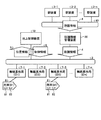
図1は、本発明の実施の形態1にかかる列車無線システムの構成図である。図1に示される列車無線システムは、ネットワーク2を介して相互に接続された地上制御装置10と防護情報管理装置20と複数の無線基地局7−1〜7−n(以下「無線基地局7」)とを有すると共に、列車8に搭載された車上無線装置81と車上制御装置82とを有して構成されている。なお、実施の形態1の列車無線システムには、一例として、1つの地上制御装置10が設けられ、この地上制御装置10に4つの無線基地局7が接続されているが、地上制御装置10および無線基地局7の数はこれに限定されるものではない。
FIG. 1 is a configuration diagram of a train radio system according to the first embodiment of the present invention. The train radio system shown in FIG. 1 includes a
図1には、車両ID#1の列車8と車両ID#2の列車8とが示され、これらの列車8には車上無線装置81と車上制御装置82が搭載されている。なお、図1では、車両搭載機器の一例として2つの機器が示されているが、実際の列車8には多種および多数の車両搭載機器(例えば速度発電機、ブレーキ制御装置、車上子など)が搭載されていることは言うまでもない。そして、これらの機器は、車両内ネットワークおよび車両間ネットワーク(図示せず)によって相互に接続されている。
FIG. 1 shows a train 8 with a
防護情報管理装置20と複数の駅装置3−1〜3−n(以下「駅装置3」は、駅の機器室などに設置され、ネットワーク40を介して接続されている。各駅装置3は、例えば、駅で人身事故などの障害が発生して非常ボタンなどが押下されたときに発信された非常情報を、防護情報4として出力する機能を有する。この防護情報4は、駅または列車8で発生した障害の防護に必要な情報であり、無線エリア内のすべての列車8に一斉送信される情報である。
The protection
防護情報管理装置20は、駅装置3からの防護情報4を受信した際、この防護情報4を、各無線基地局7に一斉送信(同報送信)する。防護情報管理装置20の詳細に関しては後述する。
When the protection
以下、列車無線システムの基本的な動作を説明する。列車8が線路上の地上子を通過した際、列車8内の車上子では地上子情報が検知される。地上子情報は、車上制御装置82において車上子情報として受信される。車上制御装置82は、この車上子情報によって地上子の位置を検知し、地上子の絶対位置を基準位置として、速度発電機からの速度情報に基づいて基準位置からの走行距離(相対距離)を算出し、線路上の列車8の位置を求める。この位置が位置情報5として車上無線装置81へ出力され、位置情報5を受け取った車上無線装置81では、各列車8を識別するための列車IDや位置情報5が無線伝送されるフレーム内のスロットにセットされる。そして、この伝送フレームは、その列車8と通信中の無線基地局7に送信される。図1の例では、ID#1の列車8からの伝送フレームがID#1の無線基地局7に送信され、ID#2の列車8からの伝送フレームがID#3の無線基地局7に送信される。伝送フレームを受信した無線基地局7では、位置情報5などが抽出され、抽出された情報は、その無線基地局7を管理する地上制御装置10に送信される。
Hereinafter, the basic operation of the train radio system will be described. When the train 8 passes the ground element on the track, the ground element information is detected by the vehicle element in the train 8. The ground control information is received as the vehicle control information by the
地上制御装置10では、自装置の管理領域を走行する列車8の位置が検知されると共に、他の地上制御装置10との間で位置情報5の授受が行われ、これらの位置情報5に基づいて停止限界位置を含む制御情報6が生成される。
In the
制御情報6は無線基地局7に送信され、無線基地局7では、この情報が所定の伝送フレーム内のスロットにセットされて車上無線装置81に送信される。この伝送フレームには、制御情報6の他にも、例えば基地局IDや防護情報管理装置20からの防護情報4などもセットされる。無線基地局7からの伝送フレームを受信した車上無線装置81では制御情報6が抽出され、抽出された制御情報6が車上制御装置82に入力される。車上制御装置82では、制御情報6に基づいて速度照査パターン(速度制御特性を示すパターン信号)が生成され、生成された速度照査パターンが速度発電機からの速度情報と比較される。そして、速度情報が速度照査パターンを超過した場合、車上制御装置82ではブレーキ指令が生成され、ブレーキ指令がブレーキ制御装置に送信される。
The
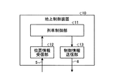
図2は、本発明の実施の形態1に係る地上制御装置10の構成図である。地上制御装置10は、無線基地局7からの位置情報5を受信する位置情報受信部12と、位置情報5に基づいて制御情報6を生成する列車制御部11と、列車制御部11で生成された制御情報6を無線基地局7に送信する制御情報送信部13とを有して構成されている。
FIG. 2 is a configuration diagram of the
地上制御装置10は、保安に関わる装置であることから、地上制御装置10では、一定の処理周期(例えば500ms)で制御情報6が生成され、かつ、送信される。従来技術では、防護情報4が地上制御装置10に入力され、この防護情報4がこの処理周期で無線基地局7に一斉送信されるように構成されている。具体的には、防護情報受信機能(図示せず)で防護情報4が受信された時点から防護情報送信機能(図示せず)から防護情報4が送信される時点までの時間が500msとなる。
Since the
そのため、防護情報4が駅装置3から発信されてから各列車8に到達するまでの到達時間は、地上制御装置10の処理周期よりも長くなる。従って、従来技術では、防護情報4が列車に到達するまでの時間を短縮するためには、地上制御装置10のハードウェアを改修する必要があり、特に列車無線システムでは、地上制御装置10が複数台用いられているため、改修に伴う多大なコストと運行への影響が大きくなる。
Therefore, the arrival time from when the protection information 4 is transmitted from the
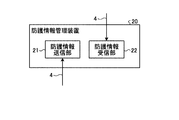
図3は、本発明の実施の形態1に係る防護情報管理装置20の構成図である。防護情報管理装置20は、各駅装置3からの防護情報4を受信する防護情報受信部22と、防護情報受信部22で受信された防護情報4を各無線基地局7へ送信する防護情報送信部21とを有して構成されている。防護情報管理装置20は、地上制御装置10と同様に保安に関わる装置であることから、防護情報管理装置20では一定の処理周期で防護情報4の伝送処理が行われる。
FIG. 3 is a configuration diagram of the protection
ただし、防護情報管理装置20の処理周期は、地上制御装置10の処理周期よりも短い時間に設定され、例えば、地上制御装置10の処理周期の10分の1の周期(50ms)に設定されている。具体的には、防護情報受信部22で防護情報4が受信された時点から防護情報送信部21から防護情報4が送信された時点までの時間が50msとなる。
However, the processing cycle of the protection
このことにより、防護情報4が発信されてから各列車8に到達するまでの到達時間は、従来技術における到達時間よりも大幅に短縮される。なお、防護情報管理装置20の処理周期は、50msに限定されるものではなく、地上制御装置10の処理周期よりも短い時間であればよいものとする。
As a result, the arrival time from when the protection information 4 is transmitted to the arrival of each train 8 is significantly shortened compared to the arrival time in the prior art. It should be noted that the processing cycle of the protection
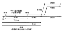
図4は、防護情報4の内容を説明するための第1の図である。図4には線路50の一例が模式的に示され、線路50は複数のブロック(例えばB1001〜B1005)に区分され、ブロックB1001の始端と終端には白抜きの丸印が印されている。車上制御装置82は、例えば、ブロックB1001の始端に設置された地上子(図示せず)の絶対位置を基準位置として、この基準位置からの走行距離を算出することによってブロックB1001内における列車8の位置を求め、この位置を位置情報5として地上制御装置10に送信する。なお、列車8には地上子情報を検知する車上子が先頭車両と後尾車両とに設けられている。そのため、車上制御装置82は、ブロック内における列車8の位置として列車前部位置や列車後部位置などを求めることができ、これらの情報を位置情報5として送信する。
FIG. 4 is a first diagram for explaining the contents of the protection information 4. FIG. 4 schematically shows an example of the
経路R1001は、例えばブロックB1001、B1002、B1005の順に列車が進行する経路を表し、経路R1003は、例えばブロックB1001、B1002、B1003、B1004の順に列車が進行する経路を表している。この経路に関する情報は、地上制御装置10で管理されており、例えば地上制御装置10において制御情報6に含められ各列車8に送信される。
The route R1001 represents a route on which the train proceeds, for example, in the order of blocks B1001, B1002, and B1005, and the route R1003 represents a route on which the train proceeds, for example, in the order of blocks B1001, B1002, B1003, and B1004. Information on this route is managed by the
図5は、防護情報4の内容を説明するための第2の図であり、図4には防護情報4に含まれる情報の一例が示されている。防護情報4には、「時刻情報」と、全ての列車8を即時停止(一斉即時停止)すべきか否かを表すフラグと、「一斉即時停止」ではない場合における具体的な防護範囲を表すための「防護情報1」、「防護情報2」とが含まれる。
FIG. 5 is a second diagram for explaining the contents of the protection information 4. FIG. 4 shows an example of information included in the protection information 4. The protection information 4 indicates “time information”, a flag indicating whether or not all trains 8 should be stopped immediately (simultaneous immediate stop), and a specific protection range in the case of not being “simultaneous immediate stop”. "
例えば「防護情報1」に記される防護範囲(始端から終端までの範囲)に向かって列車8が走行しているときに、「一斉即時停止」のフラグが「0」、かつ、この防護範囲が記された防護情報4が列車8に送信された場合、当該列車8の車上制御装置82では、この防護範囲よりも手間で列車8が停止するように、速度照査パターンが生成される。一方、「一斉即時停止」のフラグが「1」の場合、防護範囲に係わらず各列車8を即座に停止させる必要があるため、この防護情報4を受信した列車8の車上制御装置82では、即座にブレーキ指令が生成されて列車8が停止される。
For example, when the train 8 is traveling toward the protection range (the range from the start to the end) described in “
以上に説明したように、実施の形態1にかかる列車無線システムは、列車8が走行する線路50上に配置された地上子からの地上子情報と列車8で検出された列車速度とに基づいて列車8の位置情報5を生成すると共に、列車速度を速度照査パターンに照査して列車速度を制御する車上制御装置82と、車上制御装置82からの位置情報5を地上側に送信する車上無線装置81と、線路50が複数の制御領域に区分され、各制御領域に配置され車上無線装置81との間で無線通信を行う複数の無線基地局7と、無線基地局7を介して位置情報5を受信し、この位置情報5に基づいて、列車8の走行を第1の一定処理周期で制御する地上制御装置10と、駅または列車で発生した障害に起因して発生する可能性のある二次的障害を防ぐ防護情報4を、第1の一定処理周期よりも短い第2の一定処理周期で各無線基地局7に送信する防護情報管理装置20と、を備え、各無線基地局7は、防護情報管理装置20からの防護情報4を車上無線装置81へ送信するように構成されている。この構成により、地上制御装置10を改修しなくても、防護情報4が発信されてからこの防護情報4が列車8に到達するまでの時間を大幅に短縮することができることから、コストを増大させることなく円滑な列車運行を実現することができる。
As described above, the train radio system according to the first embodiment is based on the ground element information from the ground element arranged on the
実施の形態2.
図6は、本発明の実施の形態2にかかる列車無線システムの構成図である。実施の形態1との相違点は、地上制御装置10および防護情報管理装置20の代わりに、地上制御装置10Aおよび防護情報管理装置20Aが用いられ、地上制御装置10Aからの列車情報9がネットワーク30を介して防護情報管理装置20Aに入力され、防護情報管理装置20Aではこれらの情報に基づいて防護情報4Aを生成するように構成されている点である。実施の形態2において、実施の形態1と同一または類似の部分には同一または類似の符号を付してその説明を省略し、ここでは異なる部分についてのみ述べる。
FIG. 6 is a configuration diagram of a train radio system according to the second embodiment of the present invention. The difference from the first embodiment is that the
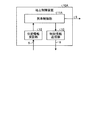
図7は、本発明の実施の形態2に係る地上制御装置10Aの構成図である。実施の形態1との相違点は、列車制御部11の代わりに列車制御部11Aが用いられている点であり、列車制御部11Aは、位置情報受信部12からの位置情報5に基づいて、制御情報6を生成すると共に列車情報9を生成する。
FIG. 7 is a configuration diagram of a
地上制御装置10Aは、実施の形態1の地上制御装置10と同様に保安に関わる装置であることから、地上制御装置10Aでは、一定の処理周期(例えば500ms)で制御情報6と列車情報9が生成され、かつ、送信される。
Since the
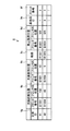
図8は、列車情報9に含まれる情報の一例を示す図である。列車情報9には、列車8を識別するための列車ID9g、当該列車8の列車前部位置9a、当該列車8の列車後部位置9b、当該列車8の経路9c、当該列車8の停止限界位置9d、当該列車8と通信中の無線基地局7を識別するための基地局ID9e、および、無線基地局7と車上無線装置81との間で伝送されるフレームのスロット番号9fなどが含まれている。
FIG. 8 is a diagram illustrating an example of information included in the
列車制御部11A(図7参照)では、走行中の列車8と、この列車8と通信中の無線基地局7と、当該列車8の経路とが管理されており、列車制御部11Aは、位置情報5を受信したとき、列車8毎に、列車ID9gと基地局ID9eとスロット番号9fと列車前部位置9aと列車後部位置9bと経路9cと停止限界位置9dとを対応付け、これらの情報を列車情報9として防護情報管理装置20Aに出力する。
In the train control unit 11A (see FIG. 7), the running train 8, the radio base station 7 in communication with the train 8, and the route of the train 8 are managed. The train control unit 11A When the
図9は、本発明の実施の形態2に係る防護情報管理装置20Aの構成図である。防護情報管理装置20Aの処理周期は、実施の形態1と同様に地上制御装置10Aの処理周期よりも短い時間(例えば50ms)に設定されている。実施の形態1との相違点は、列車情報管理部23と線路情報データベース25と列車情報管理テーブル24とが設けられ、さらに防護情報送信部21の代わりに防護情報送信部21Aが設けられている点である。
FIG. 9 is a configuration diagram of the protection
線路情報データベース25には、線路50のブロック番号や経路などが記録される。列車情報管理テーブル24には、列車情報管理部23に入力された最新の列車情報9が記録される。
In the track information database 25, the block number and route of the
列車情報管理部23には、列車制御部11Aからの列車情報9と防護情報受信部22からの防護情報4とが入力される。この防護情報4が入力されたとき、列車情報管理部23は、列車情報管理テーブル24に記録された最新の列車情報9を参照し、この列車情報9内の列車ID9g、列車前部位置9a、列車後部位置9b、および経路9cを、線路情報データベース25内の線路情報に照合する。
Train
このことにより、各列車8の現在位置(ブロック内位置)、各列車8の経路、各列車8の経路内における防護範囲(防護範囲始端、防護範囲終端)を把握することができる。 As a result, the current position (position in the block) of each train 8, the route of each train 8, and the protection range (protection range start end, protection range end) in the route of each train 8 can be grasped.
そして、列車情報管理部23は、線路情報データベース25と列車情報管理テーブル24とを参照することにより、防護情報4を送信する必要がある列車8を判別し、この列車8と通信中の無線基地局7を防護情報4の送信先として選択する。そして、列車情報管理部23は、防護情報受信部22からの防護情報4に、この選択された無線基地局7の基地局IDと伝送フレームのスロット番号9fとを付加して防護情報送信部21Aに出力する。
And the train
なお、列車情報管理部23が列車情報管理テーブル24に記録された列車情報9を用いて、防護情報4の送信先選択動作を行う理由は以下の通りである。前述したように、地上制御装置10Aの処理周期は防護情報管理装置20Aの処理周期より長いため、列車情報管理部23が地上制御装置10Aからの列車情報9を受信したタイミングで処理を行うように構成した場合、防護情報4Aの出力タイミングが遅延する。このような遅延をなくすため、列車情報管理部23では、防護情報受信部22からの防護情報4を受信した後、即座に防護情報4の送信先を選択することができるように、列車情報管理テーブル24に記録された最新の列車情報9を用いて処理が行われる。
The reason why the train
防護情報送信部21Aでは、例えば基地局IDとIPアドレスとが対応付けられたアドレステーブルが保持されており、列車情報管理部23からの情報(防護情報4と基地局IDとスロット番号との組)を受信した防護情報送信部21Aはこの基地局IDに対応する送信先のアドレスを求め、このアドレスに防護情報4とスロット番号とを付与して、防護情報4Aとして各無線基地局7へ送信する。
The protection
この防護情報4Aを受信した無線基地局7では、伝送フレームのスロットに防護情報4がセットされ、この伝送フレームが列車8に送信される。例えば、ID#1の無線基地局7と通信中の列車8(ID#1)の経路には防護範囲があり、ID#3の無線基地局7と通信中の列車8(ID#2)の経路には防護範囲がない場合、防護情報4AはID#1の無線基地局7のみに送信される。従って、この無線基地局7では、伝送フレームのスロット5(図8参照)に防護情報4がセットされ、この防護情報4がID#1の列車8で受信される。一方、ID#3の無線基地局7では、防護情報4Aが受信されないため、この無線基地局7では伝送フレームに防護情報4がセットされることがない。従って、経路内に防護範囲が含まれる列車8(ID#1)には防護情報4を送信することができ、かつ、経路内に防護範囲が含まれない列車8(ID#2)には防護情報4が送信されない。その結果、防護情報4の正確な伝送を実現しつつ、無線の利用効率の向上を図ることができる。
In the radio base station 7 that has received the
図10は、防護情報4の送信先選択動作を説明するための第1のフローチャートである。列車情報管理部23では、列車情報管理テーブル24に記録された最新の列車情報9内の列車IDが1つずつ確認され(ステップS1)、防護情報4内の「一斉即時停止」フラグにより「一斉即時停止」であるか否かが確認される(ステップS2)。
FIG. 10 is a first flowchart for explaining the transmission destination selection operation of the protection information 4. In the train
「一斉即時停止」の場合(ステップS2,Yes)、防護情報4は、防護情報送信部21Aを介して各無線基地局7に一斉送信される(ステップS3)。「一斉即時停止」ではない場合(ステップS2,No)、列車情報管理部23では、ステップS5以降の処理が実行される。
In the case of “simultaneous stop” (step S2, Yes), the protection information 4 is simultaneously transmitted to each radio base station 7 via the protection
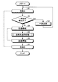
図11は、防護情報4の送信先選択動作を説明するための第2のフローチャートである。列車情報管理部23では、線路情報データベース25に記録された情報と、列車情報管理テーブル24に記録された列車情報9と、防護情報受信部22からの防護情報4とに基づいて、各列車8の経路に防護範囲(防護範囲始端または防護範囲終端)が含まれているか否かが判断される(ステップS10)。
FIG. 11 is a second flowchart for explaining the transmission destination selection operation of the protection information 4. In the train
列車8の経路内に防護範囲が含まれない場合(ステップS10,No)、列車情報管理部23では、当該列車8と通信中の無線基地局7が防護情報4の送信先として選択されることなく、図10に示されるステップS6の処理が行われる。
When the protection range is not included in the route of the train 8 (step S10, No), the train
列車8の経路内に防護範囲が含まれる場合(ステップS10,Yes)、列車情報管理部23では、防護範囲が列車8の後部位置より後方か否かが判断される(ステップS11)。ステップS11の処理が行われる理由は、例えば列車8の先頭車両が防護範囲を超えている場合でも当該列車8の後尾車両がこの防護範囲を超えていないときには当該列車8に防護情報4を送信する必要があるためである。
When the protection range is included in the route of the train 8 (step S10, Yes), the train
防護範囲が列車8の後部位置より後方である場合(ステップS11,Yes)、列車情報管理部23では、当該列車8と通信中の無線基地局7が防護情報4の送信先として選択されることなく、図10に示されるステップS6の処理が行われる。
When the protection range is behind the rear position of the train 8 (step S11, Yes), the train
防護範囲が列車8の後部位置より後方ではない場合(ステップS11,No)、当該列車8と通信中の無線基地局7が防護情報4の送信として選択され、選択された無線基地局7に防護情報4が送信される(ステップS12)。 When the protection range is not behind the rear position of the train 8 (step S11, No), the radio base station 7 communicating with the train 8 is selected as the transmission of the protection information 4, and the selected radio base station 7 is protected. Information 4 is transmitted (step S12).
図12は、本発明の実施の形態2に係る防護情報管理装置20Aの具体的な動作を説明するための図である。図12では、線路50のブロックB1001の始点から所定の位置(例えば200m)が防護範囲始端位置として示され、ブロックB1002の始点から所定の位置(例えば250m)が防護範囲終端位置として示されている。そして、この防護範囲始端位置から防護範囲終端位置までの防護範囲は、ID#1の列車8の経路に含まれているが、この列車8よりも前方に位置するID#2の列車8の経路内に含まれていない。
FIG. 12 is a diagram for explaining a specific operation of the protection
このように防護範囲が設けられている場合、防護情報管理装置20Aでは、ID#1の列車8に対して、この列車8の経路内に防護範囲が含まれ、かつ、この防護範囲がこの列車8の後部位置より後方ではないと判断される。また、防護情報管理装置20Aでは、ID#2の列車8に対して、この列車8の経路内に防護範囲が含まれていないと判断される。その結果、ID#1の列車8と通信中の無線基地局7では防護情報4が受信され、この防護情報4が伝送フレームにセットされて当該列車8に送信される。
When the protection range is provided in this way, in the protection
なお、実施の形態2の列車無線システムは、地上制御装置10Aからの列車情報9がネットワーク30を介して防護情報管理装置20Aに入力されるように構成されているが、地上制御装置10Aからの列車情報9がネットワーク2を介して防護情報管理装置20Aに入力されるように構成してもよい。
The train radio system according to the second embodiment is configured such that the
以上に説明したように、実施の形態2に係る地上制御装置10Aは、位置情報5を受信したとき、少なくとも無線基地局識別情報(基地局ID9e)と列車8の位置情報(列車前部位置9a、列車後部位置9b)とを、列車識別情報(列車ID9g)に対応付けた列車情報9を生成して防護情報管理装置20Aへ出力する列車制御情報出力部(列車制御部11A)を有し、防護情報管理装置20Aは、列車制御部11Aからの列車情報9を、無線基地局識別情報と列車の位置情報と列車識別情報と対応付けた状態で格納する列車情報管理テーブル列車情報管理テーブル24と、線路情報を保持する線路情報データベース25と、防護情報4に記される防護範囲と列車情報管理テーブル24に保持された列車情報9と線路情報データベース25に保持された路線情報とに基づいて、列車8の経路内に防護範囲が含まれるか否かを判断して、防護情報4の送信先の無線基地局7を選択する列車情報管理部23と、列車情報管理部23で選択された無線基地局7に防護情報4を送信する防護情報送信部21Aと、を備えるように構成されている。この構成により、列車制御部11Aで生成された列車情報9を用いて防護情報4の送信先を決定することができ、列車制御部11Aが改めて列車情報9を生成するという処理が不要であると共に、経路内に防護範囲が含まれる列車8のみに防護情報4を送信することができる。その結果、防護情報管理装置20Aの構成を簡素化することができ、さらに防護情報4の正確な伝送と無線の利用効率の向上とを両立させることができる。
As described above, when the
また、実施の形態2に係る列車情報管理部23は、列車8の経路内に防護範囲が含まれると判断したとき、この防護範囲が列車後部位置9bより後方か否かを判断して、防護情報4の送信先の無線基地局7を選択するように構成されている。この構成により、列車8の後部位置が防護範囲に含まれている場合にも当該列車8に防護情報4を送信することができ、より信頼性の高い列車無線システムを提供することができる。
Further, when the train
なお、本発明の実施の形態にかかる列車無線システムは、本発明の内容の一例を示すものであり、更なる別の公知の技術と組み合わせることも可能であるし、本発明の要旨を逸脱しない範囲で、一部を省略するなど、変更して構成することも可能であることは無論である。 The train radio system according to the embodiment of the present invention shows an example of the content of the present invention, and can be combined with another known technique, and does not depart from the gist of the present invention. Of course, it is possible to change the configuration such as omitting a part of the range.
以上のように、本発明は、主に列車無線システムに適用可能であり、特に、円滑な列車運行を実現可能な発明として有用である。 As described above, the present invention is mainly applicable to train radio systems, and is particularly useful as an invention that can realize smooth train operation.
2,30,40 ネットワーク、3−1,3−2,3−n 駅装置、4,4A 防護情報、5 位置情報、6 制御情報、7−1,7−2,7−3,7−n 無線基地局、8 列車、9 列車情報、9a 列車前部位置、9b 列車後部位置、9c 経路、9d 停止限界位置、9e 基地局ID、9f スロット番号、9g 列車ID、10,10A 地上制御装置、11,11A 列車制御部、12 位置情報受信部、13 制御情報送信部、20,20A 防護情報管理装置(情報送信装置)、21,21A 防護情報送信部、22 防護情報受信部、23 列車情報管理部、24 列車情報管理テーブル、25 線路情報データベース、50 線路、81 車上無線装置、82 車上制御装置。 2,30,40 network, 3-1, 3-2, 3-n station device, 4, 4A protection information, 5 position information, 6 control information, 7-1, 7-2, 7-3, 7-n Radio base station, 8 trains, 9 train information, 9a train front position, 9b train rear position, 9c route, 9d stop limit position, 9e base station ID, 9f slot number, 9g train ID, 10, 10A ground control device, 11, 11A Train control unit, 12 Position information reception unit, 13 Control information transmission unit, 20, 20A Protection information management device (information transmission device), 21, 21A Protection information transmission unit, 22 Protection information reception unit, 23 Train information management Part, 24 train information management table, 25 track information database, 50 track, 81 on-board wireless device, 82 on-board control device.
Claims (3)
前記車上制御装置からの前記位置情報を地上側に送信する車上無線装置と、
前記線路が複数の制御領域に区分され、前記各制御領域に配置され前記車上無線装置との間で無線通信を行う複数の無線基地局と、
前記各無線基地局を介して前記位置情報を受信し、この位置情報に基づいて前記列車の走行を第1の一定処理周期で制御する地上制御装置と、
駅または列車で発生した障害に起因して発生する可能性のある二次的障害を防ぐ防護情報を、前記第1の一定処理周期よりも短い第2の一定周期で前記各無線基地局に送信する防護情報管理装置と、
を備え、
前記各無線基地局は、前記防護情報管理装置からの防護情報を前記車上無線装置へ送信することを特徴とする列車無線システム。 The position information of the train is generated based on the ground element information from the ground element arranged on the track on which the train travels and the train speed detected by the train, and the train speed is checked against the speed verification pattern. An on-board control device for controlling the train speed;
An on-vehicle wireless device that transmits the position information from the on-vehicle control device to the ground side;
A plurality of radio base stations that divide the track into a plurality of control areas, and perform radio communication with the on-board radio device arranged in each control area;
A ground control device that receives the position information via each of the radio base stations, and controls the traveling of the train at a first constant processing cycle based on the position information;
Protective information for preventing secondary failures that may occur due to failures occurring at a station or train is transmitted to each of the radio base stations at a second fixed cycle shorter than the first fixed processing cycle. A protection information management device,
With
Each radio base station transmits the protection information from the protection information management device to the on-board wireless device.
前記防護情報管理装置は、
前記列車制御情報出力部からの列車情報を、無線基地局識別情報と列車の位置情報と列車識別情報と対応付けた状態で格納する列車情報管理テーブルと、
線路情報を保持する線路情報データベースと、
前記防護情報に記される防護範囲と、前記列車情報管理テーブルに保持された列車情報と、前記線路情報データベースに保持された路線情報とに基づいて、前記列車の経路内に前記防護範囲が含まれるか否かを判断して、前記防護情報の送信先の無線基地局を選択する列車情報管理部と、
前記列車情報管理部で選択された無線基地局に前記防護情報を送信する防護情報送信部と、
を備えたことを特徴とする請求項1に記載の列車無線システム。 The ground control device, when receiving the location information, generates train information in which at least radio base station identification information and train location information are associated with train identification information and outputs the train information to the protection information management device A control information output unit,
The protection information management device includes:
Train information management table for storing train information from the train control information output unit in a state in which radio base station identification information, train position information, and train identification information are associated with each other,
A track information database for storing track information;
The protection range is included in the route of the train based on the protection range described in the protection information, the train information held in the train information management table, and the route information held in the track information database. A train information management unit that selects a radio base station to which the protection information is transmitted;
A protection information transmission unit that transmits the protection information to the radio base station selected by the train information management unit;
The train radio system according to claim 1, further comprising:
前記列車の経路内に前記防護範囲が含まれると判断したとき、前記防護範囲が列車後部位置より後方か否かを判断して、前記防護情報の送信先の無線基地局を選択することを特徴とする請求項2に記載の列車無線システム。 The train information management unit
When it is determined that the protection range is included in the route of the train, it is determined whether or not the protection range is behind the rear position of the train, and a radio base station to which the protection information is transmitted is selected. The train radio system according to claim 2.
Priority Applications (1)
| Application Number | Priority Date | Filing Date | Title |
|---|---|---|---|
| JP2012191367A JP5955707B2 (en) | 2012-08-31 | 2012-08-31 | Train radio system |
Applications Claiming Priority (1)
| Application Number | Priority Date | Filing Date | Title |
|---|---|---|---|
| JP2012191367A JP5955707B2 (en) | 2012-08-31 | 2012-08-31 | Train radio system |
Publications (2)
| Publication Number | Publication Date |
|---|---|
| JP2014046818A true JP2014046818A (en) | 2014-03-17 |
| JP5955707B2 JP5955707B2 (en) | 2016-07-20 |
Family
ID=50606911
Family Applications (1)
| Application Number | Title | Priority Date | Filing Date |
|---|---|---|---|
| JP2012191367A Active JP5955707B2 (en) | 2012-08-31 | 2012-08-31 | Train radio system |
Country Status (1)
| Country | Link |
|---|---|
| JP (1) | JP5955707B2 (en) |
Cited By (4)
| Publication number | Priority date | Publication date | Assignee | Title |
|---|---|---|---|---|
| WO2016121003A1 (en) * | 2015-01-27 | 2016-08-04 | 三菱電機株式会社 | Train information management device and train information management method |
| JP2018070071A (en) * | 2016-11-02 | 2018-05-10 | 三菱電機株式会社 | Ground control device, radio train control system, and radio train control method |
| JP2018118651A (en) * | 2017-01-26 | 2018-08-02 | 株式会社日立製作所 | Signal security system |
| KR20210070471A (en) * | 2019-12-04 | 2021-06-15 | 한국철도기술연구원 | Resource Occupancy Method Based On Autonomous collaboration Between trains |
Citations (6)
| Publication number | Priority date | Publication date | Assignee | Title |
|---|---|---|---|---|
| JPH01315206A (en) * | 1988-03-30 | 1989-12-20 | Sumitomo Metal Ind Ltd | Method of controlling service of unmanned train |
| JPH11346198A (en) * | 1998-06-01 | 1999-12-14 | Toshiba Corp | Transmission apparatus and method |
| JP2003034249A (en) * | 2001-07-23 | 2003-02-04 | Kyosan Electric Mfg Co Ltd | System and method for controlling train |
| JP2003174407A (en) * | 2001-12-07 | 2003-06-20 | Kokusai Denki Engineering:Kk | Train radio system |
| JP2007069683A (en) * | 2005-09-06 | 2007-03-22 | Hitachi Ltd | Train approach alarm notification system and method |
| JP2009010852A (en) * | 2007-06-29 | 2009-01-15 | Mitsubishi Fuso Truck & Bus Corp | On-vehicle gateway device |
-
2012
- 2012-08-31 JP JP2012191367A patent/JP5955707B2/en active Active
Patent Citations (6)
| Publication number | Priority date | Publication date | Assignee | Title |
|---|---|---|---|---|
| JPH01315206A (en) * | 1988-03-30 | 1989-12-20 | Sumitomo Metal Ind Ltd | Method of controlling service of unmanned train |
| JPH11346198A (en) * | 1998-06-01 | 1999-12-14 | Toshiba Corp | Transmission apparatus and method |
| JP2003034249A (en) * | 2001-07-23 | 2003-02-04 | Kyosan Electric Mfg Co Ltd | System and method for controlling train |
| JP2003174407A (en) * | 2001-12-07 | 2003-06-20 | Kokusai Denki Engineering:Kk | Train radio system |
| JP2007069683A (en) * | 2005-09-06 | 2007-03-22 | Hitachi Ltd | Train approach alarm notification system and method |
| JP2009010852A (en) * | 2007-06-29 | 2009-01-15 | Mitsubishi Fuso Truck & Bus Corp | On-vehicle gateway device |
Cited By (9)
| Publication number | Priority date | Publication date | Assignee | Title |
|---|---|---|---|---|
| WO2016121003A1 (en) * | 2015-01-27 | 2016-08-04 | 三菱電機株式会社 | Train information management device and train information management method |
| JPWO2016121003A1 (en) * | 2015-01-27 | 2017-04-27 | 三菱電機株式会社 | Train information management apparatus and train information management method |
| EP3251917A4 (en) * | 2015-01-27 | 2018-08-22 | Mitsubishi Electric Corporation | Train information management device and train information management method |
| US10507853B2 (en) | 2015-01-27 | 2019-12-17 | Mitsubishi Electric Corporation | Train-information management device and train-information management method |
| JP2018070071A (en) * | 2016-11-02 | 2018-05-10 | 三菱電機株式会社 | Ground control device, radio train control system, and radio train control method |
| JP2018118651A (en) * | 2017-01-26 | 2018-08-02 | 株式会社日立製作所 | Signal security system |
| WO2018139013A1 (en) * | 2017-01-26 | 2018-08-02 | 株式会社日立製作所 | Railway signaling system |
| KR20210070471A (en) * | 2019-12-04 | 2021-06-15 | 한국철도기술연구원 | Resource Occupancy Method Based On Autonomous collaboration Between trains |
| KR102316367B1 (en) | 2019-12-04 | 2021-10-25 | 한국철도기술연구원 | Resource Occupancy Method Based On Autonomous collaboration Between trains |
Also Published As
| Publication number | Publication date |
|---|---|
| JP5955707B2 (en) | 2016-07-20 |
Similar Documents
| Publication | Publication Date | Title |
|---|---|---|
| CN103826960B (en) | train control system | |
| JP6296676B2 (en) | Train control system | |
| JP6296673B2 (en) | Train control system ground equipment | |
| JP5877539B2 (en) | Train control system | |
| CN102271986A (en) | Train safety protection method, equipment and system | |
| JP5955707B2 (en) | Train radio system | |
| CN106103236B (en) | For the method for rail vehicle repositioning and configuration system | |
| US11753053B2 (en) | Method for operating a rail vehicle network | |
| JP2013049395A (en) | Train control system | |
| JP2013095293A (en) | Train control system | |
| CN111163991B (en) | train control system | |
| JP2011045207A (en) | On-board information-intensive advanced safety train control system | |
| JP6270504B2 (en) | Train radio system | |
| JPWO2018207480A1 (en) | Automatic train security equipment and on-board equipment | |
| JP2018083495A (en) | Train operation control system | |
| CA2957517A1 (en) | Communication system and method | |
| RU2591551C1 (en) | Train control system on railway haul | |
| JP5897480B2 (en) | Train control system | |
| JP5858713B2 (en) | Train position detection system | |
| JP2010241281A (en) | Train control apparatus and train control system | |
| CN102717816A (en) | Situation processing system of locomotive operation information | |
| JP6004905B2 (en) | Train radio system | |
| JP5856935B2 (en) | Train control system | |
| JP6041771B2 (en) | Train radio system | |
| KR101619764B1 (en) | Apparatus and system for train protection in accident area |
Legal Events
| Date | Code | Title | Description |
|---|---|---|---|
| A621 | Written request for application examination |
Free format text: JAPANESE INTERMEDIATE CODE: A621 Effective date: 20140627 |
|
| A977 | Report on retrieval |
Free format text: JAPANESE INTERMEDIATE CODE: A971007 Effective date: 20150731 |
|
| A131 | Notification of reasons for refusal |
Free format text: JAPANESE INTERMEDIATE CODE: A131 Effective date: 20150804 |
|
| A521 | Request for written amendment filed |
Free format text: JAPANESE INTERMEDIATE CODE: A523 Effective date: 20150909 |
|
| A02 | Decision of refusal |
Free format text: JAPANESE INTERMEDIATE CODE: A02 Effective date: 20160126 |
|
| A521 | Request for written amendment filed |
Free format text: JAPANESE INTERMEDIATE CODE: A523 Effective date: 20160426 |
|
| A911 | Transfer to examiner for re-examination before appeal (zenchi) |
Free format text: JAPANESE INTERMEDIATE CODE: A911 Effective date: 20160510 |
|
| TRDD | Decision of grant or rejection written | ||
| A01 | Written decision to grant a patent or to grant a registration (utility model) |
Free format text: JAPANESE INTERMEDIATE CODE: A01 Effective date: 20160614 |
|
| A61 | First payment of annual fees (during grant procedure) |
Free format text: JAPANESE INTERMEDIATE CODE: A61 Effective date: 20160615 |
|
| R150 | Certificate of patent or registration of utility model |
Ref document number: 5955707 Country of ref document: JP Free format text: JAPANESE INTERMEDIATE CODE: R150 |
|
| R250 | Receipt of annual fees |
Free format text: JAPANESE INTERMEDIATE CODE: R250 |
|
| R250 | Receipt of annual fees |
Free format text: JAPANESE INTERMEDIATE CODE: R250 |
|
| R250 | Receipt of annual fees |
Free format text: JAPANESE INTERMEDIATE CODE: R250 |
|
| R250 | Receipt of annual fees |
Free format text: JAPANESE INTERMEDIATE CODE: R250 |
|
| R250 | Receipt of annual fees |
Free format text: JAPANESE INTERMEDIATE CODE: R250 |
|
| R250 | Receipt of annual fees |
Free format text: JAPANESE INTERMEDIATE CODE: R250 |
|
| R250 | Receipt of annual fees |
Free format text: JAPANESE INTERMEDIATE CODE: R250 |