JP2014040728A - Spray device for producing spray concrete - Google Patents
Spray device for producing spray concrete Download PDFInfo
- Publication number
- JP2014040728A JP2014040728A JP2012183123A JP2012183123A JP2014040728A JP 2014040728 A JP2014040728 A JP 2014040728A JP 2012183123 A JP2012183123 A JP 2012183123A JP 2012183123 A JP2012183123 A JP 2012183123A JP 2014040728 A JP2014040728 A JP 2014040728A
- Authority
- JP
- Japan
- Prior art keywords
- concrete
- base concrete
- spray
- spraying
- base
- Prior art date
- Legal status (The legal status is an assumption and is not a legal conclusion. Google has not performed a legal analysis and makes no representation as to the accuracy of the status listed.)
- Granted
Links
- 239000004567 concrete Substances 0.000 title claims abstract description 116
- 239000007921 spray Substances 0.000 title claims abstract description 31
- 239000007788 liquid Substances 0.000 claims abstract description 53
- 230000015572 biosynthetic process Effects 0.000 claims abstract description 6
- 239000000203 mixture Substances 0.000 claims abstract description 6
- 239000003795 chemical substances by application Substances 0.000 claims description 53
- 238000005507 spraying Methods 0.000 claims description 32
- 238000003756 stirring Methods 0.000 claims description 22
- 239000011378 shotcrete Substances 0.000 claims description 21
- 238000004519 manufacturing process Methods 0.000 claims description 18
- 239000004568 cement Substances 0.000 claims description 16
- XLYOFNOQVPJJNP-UHFFFAOYSA-N water Substances O XLYOFNOQVPJJNP-UHFFFAOYSA-N 0.000 claims description 13
- 238000005086 pumping Methods 0.000 claims description 6
- 238000002156 mixing Methods 0.000 description 12
- 239000000843 powder Substances 0.000 description 10
- 239000000428 dust Substances 0.000 description 9
- 230000000694 effects Effects 0.000 description 7
- 239000004570 mortar (masonry) Substances 0.000 description 7
- 238000005259 measurement Methods 0.000 description 6
- 238000010586 diagram Methods 0.000 description 5
- 238000012360 testing method Methods 0.000 description 5
- 239000011398 Portland cement Substances 0.000 description 4
- 239000000463 material Substances 0.000 description 4
- 238000012986 modification Methods 0.000 description 4
- 230000004048 modification Effects 0.000 description 4
- 238000010998 test method Methods 0.000 description 4
- 238000011161 development Methods 0.000 description 3
- 238000002347 injection Methods 0.000 description 3
- 239000007924 injection Substances 0.000 description 3
- 238000004898 kneading Methods 0.000 description 3
- 229910052751 metal Inorganic materials 0.000 description 3
- 239000002184 metal Substances 0.000 description 3
- 239000002002 slurry Substances 0.000 description 3
- 238000010521 absorption reaction Methods 0.000 description 2
- 239000003638 chemical reducing agent Substances 0.000 description 2
- 230000007774 longterm Effects 0.000 description 2
- 230000035515 penetration Effects 0.000 description 2
- 238000007586 pull-out test Methods 0.000 description 2
- 230000002787 reinforcement Effects 0.000 description 2
- -1 Aluminum compound Chemical class 0.000 description 1
- 235000010724 Wisteria floribunda Nutrition 0.000 description 1
- 239000002253 acid Substances 0.000 description 1
- 239000012615 aggregate Substances 0.000 description 1
- 229910052782 aluminium Inorganic materials 0.000 description 1
- 238000009412 basement excavation Methods 0.000 description 1
- XFWJKVMFIVXPKK-UHFFFAOYSA-N calcium;oxido(oxo)alumane Chemical compound [Ca+2].[O-][Al]=O.[O-][Al]=O XFWJKVMFIVXPKK-UHFFFAOYSA-N 0.000 description 1
- 230000000052 comparative effect Effects 0.000 description 1
- 238000009833 condensation Methods 0.000 description 1
- 230000005494 condensation Effects 0.000 description 1
- 238000010276 construction Methods 0.000 description 1
- 238000009415 formwork Methods 0.000 description 1
- 238000000691 measurement method Methods 0.000 description 1
- 238000000034 method Methods 0.000 description 1
- 239000011268 mixed slurry Substances 0.000 description 1
- 238000004321 preservation Methods 0.000 description 1
- 239000011347 resin Substances 0.000 description 1
- 229920005989 resin Polymers 0.000 description 1
- 239000004576 sand Substances 0.000 description 1
- 239000002893 slag Substances 0.000 description 1
- 229910001220 stainless steel Inorganic materials 0.000 description 1
- 239000010935 stainless steel Substances 0.000 description 1
- 238000012546 transfer Methods 0.000 description 1
Images

Landscapes
- Lining And Supports For Tunnels (AREA)
- On-Site Construction Work That Accompanies The Preparation And Application Of Concrete (AREA)
Abstract
Description
本発明は液体状急結剤を使用する吹付けコンクリート製造吹付装置に関する。 The present invention relates to a spraying concrete production spraying apparatus using a liquid quick setting agent.
山岳トンネルの建設工事で行われるトンネル掘削では、掘削したトンネル内の露呈した地山の崩落を防ぐため、当該面にコンクリート又はモルタル(以下、これらを総称し「コンクリート」と称す。)を吹付けた地山補強が行われる。吹付けコンクリートは、早く凝結させ、高い初期強度を発現させるため、セメントに水を加えて混連したコンクリート(以下、ベースコンクリートと称す。)に急結剤を添加したものが使用される。 In tunnel excavation in the construction of mountain tunnels, concrete or mortar (hereinafter collectively referred to as “concrete”) is sprayed on the surface to prevent collapse of exposed ground in the excavated tunnel. Reinforcement of natural ground is performed. In order to quickly set and develop a high initial strength, shotcrete is used by adding rapid setting agent to concrete mixed with water by adding water to cement (hereinafter referred to as base concrete).
急結剤には、粉末状の急結剤(以下、粉体急結剤と称す。)と液体状の急結剤(以下、液体急結剤と称す。)がある。 The quick setting agent includes a powdery quick setting agent (hereinafter referred to as a powder quick setting agent) and a liquid quick setting agent (hereinafter referred to as a liquid quick setting agent).
粉体急結剤を用いる吹付けコンクリートの吹付装置は、空気圧送される粉体急結剤の供給管とポンプ圧送されたベースコンクリートの圧送管との連結箇所にT字又はY字管等の三方口の合流管を設けて両者を混合させる。合流管の先に設けたノズルの吐出口より混合物が噴射される。また、円滑且つ短時間に混合させる上で、ベースコンクリートの圧送には、ほぐしエアが吹き込まれるのが一般的である。ほぐしエアの導入でベースコンクリートが団子状になって圧送されるのを防ぎ、解されたベースコンクリートと急結剤粉末との混合性が高まる。しかし、完全に混合させることはできず、ベースコンクリートと混合できずに吹付けられてしまう急結剤粉末が残存し、これが坑内粉塵になり、また混合不十分なため急結剤不足の吹付けコンクリートが吹付け面からリバウンドを起こすなど作業環境の悪化も指摘されている。 Spraying equipment for shotcrete using a powder quick-setting agent is a T-shaped or Y-shaped pipe or the like at the connecting point between a pneumatic quick-feed powder quick-setting agent supply pipe and a pumped base concrete pressure-feed pipe. A three-way confluence pipe is provided to mix the two. The mixture is ejected from a discharge port of a nozzle provided at the end of the junction pipe. Moreover, in order to mix smoothly and in a short time, loosening air is generally blown into the pressure feed of the base concrete. The introduction of loosening air prevents the base concrete from being dumped and pumped, and improves the mixability of the dissolved base concrete and quick setting powder. However, it is not possible to mix completely, and quick setting powder remains that cannot be mixed with the base concrete and is sprayed, which becomes underground dust, and insufficient mixing due to insufficient mixing. It has also been pointed out that the working environment deteriorates, such as concrete rebounding from the spray surface.
無粉塵化のため、液体状の急結剤を用いることがある。液体急結剤を使用する吹付けコンクリートの吹付け装置は、粉体急結剤使用の装置とは一般に構造が異なる。粉体急結剤のように噴出ノズルより手前でベースコンクリートと液体状の急結剤を混合させると、粉体よりも瞬結性が強いので、狭窄したノズル通路部が閉塞する虞がある。そのため、両者の混合はノズル端部付近又はノズルから噴出後に行われる。具体的には、例えば、二重管構造の吹付けノズルを使用し、内管内を圧縮空気で輸送された液体状急結剤を通し、その外側の外管内をポンプ圧送されたベースコンクリートを通し、両者を噴出直後に合流させることで混合させたり(例えば、特許文献1参照。)、ノズルに取り付けたシャワーリング管を用いて液体状急結剤の添加が行われている。(例えば、特許文献2、3参照。)また、このような混合手段(添加手段)をとるため、ベースコンクリートはポンプ圧送のみで吹付ノズルまで圧送され、ほぐしエアは使用されない。
A liquid quick-setting agent may be used to reduce dust. A spraying apparatus for shotcrete that uses a liquid quick-set agent generally differs in structure from an apparatus that uses a powder quick-set agent. When the base concrete and the liquid quick setting agent are mixed in front of the ejection nozzle as in the case of the powder quick setting agent, since the quick setting property is stronger than the powder, the narrowed nozzle passage may be blocked. Therefore, both are mixed near the nozzle end or after ejection from the nozzle. Specifically, for example, a spray nozzle having a double pipe structure is used, a liquid quick-set agent transported by compressed air is passed through the inner pipe, and a base concrete pumped through the outer pipe outside is passed. The liquid quick setting agent is added using a shower ring tube attached to a nozzle, for example, by mixing them together immediately after jetting (see, for example, Patent Document 1). (For example, refer to
一方で、ほぐしエアによる圧送力補助が無いので、ベースコンクリートは流動性が低下し易い。流動性が低下したベースコンクリートは急結剤との均一な混合が困難になり、吹付けコンクリートの付着性状や強度発現性にムラが生じ易く、掘削した地山の保全に支障をきたす虞がある。流動性向上のため混練水量を増加させるとコンクリート強度の著しい低下を起こす。 On the other hand, since there is no pumping force assistance by loosening air, the base concrete is liable to decrease in fluidity. Base concrete with reduced fluidity becomes difficult to mix with the rapid setting agent, and adhesion properties and strength development of shotcrete are likely to be uneven, which may hinder the preservation of excavated ground. . Increasing the amount of kneading water to improve fluidity causes a significant decrease in concrete strength.
つまり、従来技術の添加手段では、流動性の低いベースコンクリートの外部から液体急結剤を添加するものである。そのため、管内壁周りを流れるベースコンクリートには液体急結剤が混合されるが、管内部を流れるベースコンクリートには液体急結剤が混合されないまま、吹付けコンクリートがノズルから噴射される。 That is, in the conventional addition means, the liquid quick-setting agent is added from the outside of the base concrete having low fluidity. Therefore, the liquid quick setting agent is mixed in the base concrete flowing around the inner wall of the pipe, but the spray concrete is injected from the nozzle without mixing the liquid quick setting agent in the base concrete flowing in the pipe.
本発明は上記課題を解決するものであり、液体急結剤をベースコンクリートに均一に混合することができ、均質で安定した性状の吹付けコンクリートを製造し吹付けることができる吹付けコンクリート製造吹付装置を提供することを目的とする。 The present invention solves the above-mentioned problems, and can spray a liquid quick setting agent uniformly into base concrete, and can produce and spray spray concrete with uniform and stable properties. An object is to provide an apparatus.
本願発明者は、液体状の急結剤を用いる吹付けコンクリート製造吹付装置において、ベースコンクリートの流動性低下を抑制し、液体状急結剤との混合性を高めることができる装置を検討した結果、ベースコンクリートの流れを撹拌し、撹拌されたベースコンクリートに液体状急結剤を添加すれば、液体状急結剤とベースコンクリートとの混合性が飛躍的に高まることを見いだした。更に、ベースコンクリートの流れを撹拌する具体的な構成について検討し、本発明を完成した。 The inventor of the present application, as a result of studying an apparatus capable of suppressing a decrease in the fluidity of the base concrete and improving the mixing property with the liquid quick setting agent in the spray concrete manufacturing spraying apparatus using the liquid quick setting agent. It was found that if the flow of the base concrete is stirred and the liquid quick setting agent is added to the stirred base concrete, the mixing property of the liquid quick setting agent and the base concrete is dramatically increased. Furthermore, the concrete structure which stirs the flow of base concrete was examined, and this invention was completed.
上記課題を解決する本発明は、少なくとも水及びセメントとの混練物であるベースコンクリートと、液体状急結剤と、を含有する吹付けコンクリートを製造し吹き付ける吹付けコンクリート製造吹付装置であって、前記ベースコンクリートを圧送する圧送ポンプと、前記圧送ポンプに連設されたベースコンクリート供給管と、前記ベースコンクリート供給管に設けられ、該ベースコンクリート供給管内を流れるベースコンクリートを撹拌する撹拌室と、前記撹拌室で撹拌されたベースコンクリートに前記液体状急結剤を添加する添加装置と、前記添加装置に前記液体状急結剤を供給する液体急結剤供給管と、前記吹付けコンクリートを噴射する噴射ノズルとを備えることを特徴とする。 The present invention for solving the above problems is a spray concrete production spraying device for producing and spraying spray concrete containing at least base concrete which is a mixture of water and cement, and a liquid quick setting agent, A pump for pumping the base concrete; a base concrete supply pipe connected to the pump; a stirring chamber provided in the base concrete supply pipe for stirring the base concrete flowing in the base concrete supply pipe; An adding device for adding the liquid quick setting agent to the base concrete stirred in the stirring chamber, a liquid quick setting agent supply pipe for supplying the liquid quick setting agent to the adding device, and spraying the shotcrete And an injection nozzle.
このように吹付けコンクリート製造吹付装置では、ベースコンクリート供給管内を流れるベースコンクリートは、撹拌室により撹拌される。添加装置は、撹拌されたベースコンクリートに、液体急結剤を添加する。これにより、液体急結剤をベースコンクリートに均一に混合することができる。 Thus, in the shotcrete production spraying apparatus, the base concrete flowing in the base concrete supply pipe is stirred by the stirring chamber. The addition device adds a liquid quick-setting agent to the stirred base concrete. Thereby, a liquid quick setting agent can be uniformly mixed with base concrete.
本発明において、好ましくは、前記撹拌室は、内壁に突起物が配設された円筒管である。 In the present invention, preferably, the stirring chamber is a cylindrical tube in which a protrusion is disposed on an inner wall.
これにより、ベースコンクリート供給管内を流れるベースコンクリートが、突起物に衝突すると、流れの向きを変えられ、撹拌される。 As a result, when the base concrete flowing in the base concrete supply pipe collides with the protrusions, the direction of the flow is changed and stirred.
本発明において、好ましくは、前記突起物は、複数の旋流形成羽根である。 In the present invention, preferably, the protrusion is a plurality of swirl forming blades.
これにより、ベースコンクリート供給管内を流れるベースコンクリートが、旋流形成羽根に衝突すると、流れの向きを変えられ、旋流化される。その結果、より、均一性、混合性が向上する。 Thus, when the base concrete flowing in the base concrete supply pipe collides with the swirl forming blade, the flow direction is changed and swirled. As a result, the uniformity and mixing properties are further improved.
本発明において、好ましくは、前記撹拌室は、前記旋流形成羽根が形成する旋流により流れ方向に対し回転可能である。 In the present invention, preferably, the agitating chamber is rotatable with respect to the flow direction by the swirl formed by the swirl forming blade.
これにより、旋流形成羽根が抵抗となることを抑制し、ノズルが閉塞することを防止する。 Thereby, it is suppressed that a swirl forming blade | wing becomes resistance, and it prevents that a nozzle is obstruct | occluded.
本発明において、好ましくは、前記旋流形成羽根は、底辺長さ:羽根高=1:1〜2:1であり、羽根高が、円筒管直径の5〜50%であり、底辺が流れ方向に対し10〜30度の角度をなす。 In the present invention, preferably, the swirl forming blade has a base length: blade height = 1: 1 to 2: 1, the blade height is 5 to 50% of the diameter of the cylindrical tube, and the base is the flow direction. An angle of 10 to 30 degrees with respect to the angle.
これにより、充分な旋流を形成するとともに、旋流形成羽根が抵抗となることを抑制する。 Thereby, while forming sufficient swirl, it suppresses that a swirl formation blade | wing becomes resistance.
本発明において、好ましくは、2〜4個の前記旋流形成羽根が、流れ方向並列に配設されている。 In the present invention, preferably, 2 to 4 of the swirl forming blades are arranged in parallel in the flow direction.
これにより、充分な旋流を形成するとともに、旋流形成羽根が抵抗となることを抑制する。 Thereby, while forming sufficient swirl, it suppresses that a swirl formation blade | wing becomes resistance.
本発明において、好ましくは、前記添加装置は、シャワーリング管である。 In the present invention, preferably, the adding device is a shower ring tube.
これにより、より、均一性、混合性が向上する。 Thereby, the uniformity and the mixing property are further improved.
本願発明のコンクリート製造吹付装置は、液体急結剤をベースコンクリートに均一に混合することができ、これにより、均質で安定した性状の吹付けコンクリートを製造できる。その結果、粉塵発生やリバウンドを抑制しつつ、初期強度の高い吹付けコンクリートを地山に吹付けることができる。 The concrete production spraying apparatus of the present invention can uniformly mix the liquid quick-setting agent with the base concrete, and thereby can produce spray concrete having a uniform and stable property. As a result, spray concrete with high initial strength can be sprayed on natural ground while suppressing dust generation and rebound.
〜構成〜
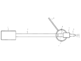
図1は、本実施形態の吹付けコンクリート製造吹付装置の概略構成図である。吹付けコンクリート製造吹付装置は、圧送ポンプ1と、ベースコンクリート供給管2と、旋流室3と、シャワーリング管4と、液体急結剤供給管5と、噴射ノズル6とを備える。
~Constitution~
FIG. 1 is a schematic configuration diagram of a shotcrete production spraying apparatus according to the present embodiment. The shotcrete production spraying apparatus includes a
吹付けコンクリート製造吹付装置は、吹付けコンクリートを製造し、地山に吹付けるものである。吹付けコンクリートはベースコンクリートと液体状急結剤とを含有する。 The shotcrete production spraying device manufactures shotcrete and sprays it on natural ground. Shotcrete contains base concrete and a liquid setting agent.
ベースコンクリートは、少なくともセメントと水との混練物である。用いるセメントは特に限定されず、例えば、普通ポルトランドセメントや早強ポルトランドセメントなどの各種ポルトランドセメント、スラグセメント等の各種混合セメント、エコセメント等の特殊セメントも使用可能である。該混練物には、骨材やモルタルやコンクリートで使用できる混和剤・混和材を含むものであっても良い。ただし、凝結促進成分やカルシウムアルミネート等の急結成分を予め含むものなど本発明の効果を阻害する成分の含有は好ましくない。また、混練水の配合質量は含有するセメント質量100部に対し、40〜65部が好ましい。40部を超えると強度低下大きく、地山補強に適さないことがあることがあるため適当ではない。一方、65部を超えると著しく流動性が低下し、ポンプ圧送が困難になることがあるので適当ではない。混練は例えばモルタルミキサー等の混合装置で行い、そこから混練物(混連スラリー)を圧送ポンプ1にホース接続して輸送しても良いし、また別途工場でベースコンクリートを作製し、アジテーター車で搬送して圧送ポンプ1に投入しても良い。
Base concrete is a mixture of at least cement and water. The cement to be used is not particularly limited. For example, various portland cements such as ordinary portland cement and early-strength portland cement, various mixed cements such as slag cement, and special cements such as ecocement can be used. The kneaded product may contain an admixture / admixture that can be used in aggregate, mortar, or concrete. However, it is not preferable to contain a component that inhibits the effects of the present invention, such as a component that includes a setting component such as a setting accelerator or a rapid setting component such as calcium aluminate. Further, the blending mass of the kneaded water is preferably 40 to 65 parts with respect to 100 parts of the cement mass contained. If it exceeds 40 parts, the strength is greatly reduced, and it may not be suitable for natural ground reinforcement. On the other hand, if it exceeds 65 parts, the fluidity is remarkably lowered, and pumping may become difficult. The kneading may be carried out with a mixing device such as a mortar mixer, and the kneaded product (mixed slurry) may be transported by connecting it with a hose to the
液体急結剤は、特に限定されるものではなく、モルタルやコンクリートに使用できる液体状の急結剤なら何れのものでも使用できる。具体的には例えば、市販の液体急結剤や、粉体急結剤をスラリー化したもの等をあげることができる。ベースコンクリートに添加する液体状の急結剤の添加量は、特に制限されず成分等に応じて適宜定めれば良い。好ましくは例えば市販の液体急結剤を使用する場合、ベースコンクリートに含有されたセメント質量100部に対し、5〜12部が好ましい。5部未満では充分な急結性が得られず、早期強度発現性に劣るので適当ではない。一方、12部を超えると凝結が瞬結化し、ノズル6が閉塞する虞があるので適当ではない。 The liquid quick-setting agent is not particularly limited, and any liquid quick-setting agent that can be used for mortar and concrete can be used. Specifically, for example, a commercially available liquid accelerator or a slurry of a powder accelerator can be used. The addition amount of the liquid quick-setting agent added to the base concrete is not particularly limited and may be appropriately determined according to the components. Preferably, for example, when a commercially available liquid quick-setting agent is used, 5 to 12 parts are preferable with respect to 100 parts of cement mass contained in the base concrete. If it is less than 5 parts, sufficient rapid setting properties cannot be obtained, and early strength development is inferior. On the other hand, if it exceeds 12 parts, condensation is instantaneously set and the nozzle 6 may be blocked, which is not appropriate.
圧送ポンプ1は、一般に使用されている吹付モルタルやコンクリート用の粉体急結剤の圧送ポンプとは異なり、ベースコンクリート等の混練スラリーを、噴射ノズル6元まで、ほぐしエアを供給・使用することなく、ピストン、スクイズ又はプランジャー等によって混練スラリーを圧送する方式の液体圧送用のポンプである。かかる方式のポンプであれば細部構造等は特に限定されない。
Unlike the commonly used spraying mortar and concrete powder rapid setting pumps for concrete, the
ベースコンクリート供給管2は、圧送ポンプ1の圧力によりベースコンクリートを圧送するものであり、スラリー状のベースコンクリートの輸送が可能な管であれば限定されず、例えば、ステンレス等の金属製配管や耐圧性の金属メッシュ入り樹脂製ホース等を挙げることができる。その内径も特に制限されず、好ましくは概ね127〜152mm(5〜6インチ)とする。
The base
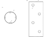
旋流室3は、ベースコンクリート供給管2の最下流位置に設けられ、ベースコンクリート供給管2内を流れるベースコンクリートを旋流化して撹拌する。旋流室3は円筒管であり、円筒管内壁には複数の旋流形成羽根7が配設されている。
The whirling
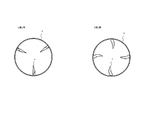
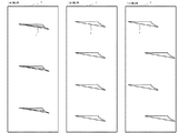
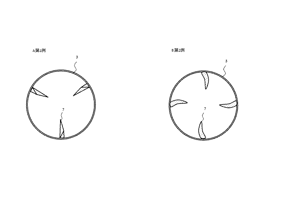
図2は旋流室3の概略断面図であり、図3は旋流室3内部の展開平面図である。旋流形成羽根7の形状は限定されるものでない。旋流形成羽根7の第1例および第2例を記載する。
FIG. 2 is a schematic cross-sectional view of the
第1例では、旋流形成羽根7は、2つの三角形状の平面から構成されている。第2例では、旋流形成羽根7は、円弧状の曲面から構成されている。
In the first example, the
第1例では、3つの旋流形成羽根7が流れ方向並列に配設され、第2例では、4つの旋流形成羽根7が流れ方向並列に配設されている。旋流形成羽根7は2〜4個であることが好ましい。2個未満(1個)では、充分な旋流を形成できないため、適当ではない。一方、4個を超えると、旋流形成羽根7が抵抗となり、ノズル6が閉塞する虞があるので適当ではない。
In the first example, three
第1・2例では、旋流形成羽根7が流れ方向並列に配設されているが、旋流形成羽根7が4個である場合、千鳥配置としてもよい(第3例)。
In the first and second examples, the
ベースコンクリート供給管2内を流れるベースコンクリートが、旋流形成羽根7に衝突すると、流れの向きを変えられ、旋流化される。
When the base concrete flowing in the base
上述の通り、旋流形成羽根7の形状は限定されるものでないが、以下の特徴を有していることが好ましい。
As described above, the shape of the
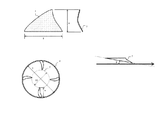
底辺長さB:羽根高H=1:1〜2:1であることが好ましい。H/Bが0.5未満、すなわち、羽根高が低すぎる場合は、充分な旋流を形成できないため、適当ではない。一方、H/Bが1.0超、すなわち、底辺長さが短すぎる場合は、充分な旋流を形成できないため、適当ではない。 Base length B: blade height H = 1: 1 to 2: 1 is preferable. If H / B is less than 0.5, that is, if the blade height is too low, it is not appropriate because a sufficient swirl cannot be formed. On the other hand, if H / B is more than 1.0, that is, if the base length is too short, it is not appropriate because sufficient vortex cannot be formed.
羽根高Hが、円筒管直径Dの5〜50%であることが好ましい。羽根高Hが円筒管直径Dの5%未満、すなわち、羽根高が低すぎる場合は、充分な旋流を形成できないため、適当ではない。一方、羽根高Hが円筒管直径Dの50%超であると、旋流形成羽根7が抵抗となり、ノズル6が閉塞する虞があるので適当ではない。
The blade height H is preferably 5 to 50% of the cylindrical tube diameter D. If the blade height H is less than 5% of the diameter D of the cylindrical tube, that is, if the blade height is too low, it is not appropriate because a sufficient swirl cannot be formed. On the other hand, if the blade height H is more than 50% of the cylindrical tube diameter D, the
旋流形成羽根7の底辺が流れ方向に対し10〜30度の角度θをなすことが好ましい。角度θが10度未満であると、充分な旋流を形成できないため、適当ではない。一方、角度θが30度超であると、旋流形成羽根7が抵抗となり、ノズル6が閉塞する虞があるので適当ではない。
It is preferable that the bottom of the
円筒管内の旋流形成羽根7による障害がない空間(有効空間)の直径D2が、円筒管直径Dの50%以上であることが好ましい。有効径D2が円筒管直径Dの50%未満であると、旋流形成羽根7が抵抗となり、ノズル6が閉塞する虞があるので適当ではない。
It is preferable that the diameter D2 of the space (effective space) free from obstruction by the
図4は、旋流形成羽根7の底辺長さB、羽根高H、底辺のなす角度θ、円筒管直径D、有効径D2を説明する図である。
FIG. 4 is a diagram for explaining the bottom length B, blade height H, angle θ formed by the bottom, cylindrical tube diameter D, and effective diameter D2 of the
旋流室3はベアリング(図示省略)により回転可能に保持される。旋流形成羽根7が形成する旋流が作用し、円筒管が回転する。流量が多くなると、旋流形成羽根7に起因する抵抗も増えるが、円筒管回転により抵抗増を抑制できる。
The whirling
シャワーリング管4は、管内を通過するベースコンクリートに管内面周囲に設けられた複数の添加穴から均一に液体急結剤を添加する添加装置である。シャワーリング管4は旋流室3と連続して設けられている。なお、シャワーリング管4に準ずる均一混合効果が得られれば、他の添加装置でもよい。
The shower ring pipe 4 is an addition device that uniformly adds a liquid quick-set agent to a base concrete passing through the pipe from a plurality of addition holes provided around the inner surface of the pipe. The shower ring tube 4 is provided continuously with the whirling
液体急結剤供給管5は、シャワーリング管4に液体急結剤を供給するものであり、液体輸送が可能な管であれば限定されず、例えば、ステンレス等の金属製配管や耐圧性の金属メッシュ入り樹脂製ホース等を用いることができる。また、液体急結剤の輸送には、固結・閉塞を避ける上で、圧縮空気等の圧送ガスを併用することが望ましい。その内径も特に制限されず、好ましくは概ね5〜30mm(例えば18mm)とする。
The liquid quick-setting
噴射ノズル6は、好ましくはシャワーリング管4に直結された噴出管であり、一般に連続的に縮径することにより、吹付けコンクリートを噴射する。 The spray nozzle 6 is preferably a spray pipe directly connected to the shower ring pipe 4 and sprays shotcrete by generally reducing the diameter continuously.
〜作用・効果〜
図5は、本実施形態の作用・効果を説明する図である。従来技術と比較することにより、本実施形態の作用・効果を説明する。図5Aは、従来技術のシャワーリングの動作を示し、図5Bは、本実施形態のシャワーリングの動作を示す。
-Action and effect-
FIG. 5 is a diagram for explaining the operation and effect of the present embodiment. The operation and effect of this embodiment will be described by comparing with the prior art. FIG. 5A shows the operation of the conventional shower ring, and FIG. 5B shows the operation of the shower ring of the present embodiment.
シャワーリング管4は、管内を通過するベースコンクリートに管内面周囲に設けられた複数の添加穴から均一に液体急結剤を添加する。 The shower ring tube 4 uniformly adds the liquid quick-setting agent from a plurality of addition holes provided around the inner surface of the base concrete passing through the tube.
従来技術において、管内壁周りを流れるベースコンクリートには液体急結剤が混合されるが、管内部を流れるベースコンクリートには液体急結剤が混合されない。すなわち、均一性に係る課題があった。 In the prior art, the liquid quick setting agent is mixed with the base concrete flowing around the inner wall of the pipe, but the liquid quick setting agent is not mixed with the base concrete flowing inside the pipe. That is, there was a problem related to uniformity.
本実施形態においては、旋流室3によりベースコンクリートは旋流化されている。管内壁周りを流れるベースコンクリートには液体急結剤が混合されるとともに、液体急結剤が混合されたベースコンクリートは内部に移動し、管内部を流れるベースコンクリートに混合される。一方、管内部を流れるベースコンクリートは外部に移動し、液体急結剤が混合される。これにより、液体急結剤をベースコンクリートに均一に混合することができる。
In the present embodiment, the base concrete is swirled by the
均質で安定した性状の吹付けコンクリートを製造できる結果、粉塵発生やリバウンドを抑制しつつ、初期強度の高い吹付けコンクリートを地山に吹付けることができる。 As a result of being able to produce spray concrete with uniform and stable properties, spray concrete with high initial strength can be sprayed onto natural ground while suppressing dust generation and rebound.
粉塵発生を抑制することにより、坑内環境が改善できる。リバウンドを抑制することにより、材料ロスを減らし、材料コストを削減できる。 By suppressing dust generation, the underground environment can be improved. By suppressing rebound, material loss can be reduced and material cost can be reduced.
〜変形例〜
本願発明は上記実施形態に限定されるものでなく、技術思想の範囲で種々の変形が可能である。
~ Modification ~
The present invention is not limited to the above embodiment, and various modifications can be made within the scope of the technical idea.
上記実施形態では、旋流室3は回転可能に保持されているが、旋流形成羽根7に起因する抵抗によりノズル6が閉塞する虞がなければ、固定されていてもよい。
In the above embodiment, the whirling
上記実施形態では、旋流室3はベースコンクリート供給管2内を流れるベースコンクリートを旋流化して撹拌するが、充分な撹拌ができれば、旋流化しなくともよい。
In the above embodiment, the whirling
図6は、変形例の1つである撹拌室13の概略断面図(図6A)と、撹拌室13内部の展開平面図(図6B)である。撹拌室13は円筒管であり、円筒管内壁には4つの撹拌突起17が配設されている。撹拌突起17は略ドーム形状をしている。
FIG. 6 is a schematic cross-sectional view (FIG. 6A) of the stirring
ベースコンクリート供給管2内を流れるベースコンクリートが、撹拌突起17に衝突すると、流れの向きを変えられ、撹拌される。
When the base concrete flowing in the base
<概要>
粉塵濃度、はね返り率(リバウンド)、コンクリート強度について、従来技術の装置(旋流室なし)と上記実施形態の装置(旋流室あり)との比較試験を実施した。
<Overview>
For dust concentration, rebound rate (rebound), and concrete strength, a comparative test was conducted between the apparatus of the prior art (without the whirling chamber) and the apparatus of the above embodiment (having the whirling chamber).
またセメントの種類(セメントA/B)に依らず、効果が得られることを確認した。 It was also confirmed that the effect was obtained regardless of the type of cement (cement A / B).
<使用材料>
セメントA:普通ポルトランドセメント(太平洋セメント社製)(記号;OPC)
セメントB:エコセメント(たまエコセメント社製)(記号;ECO)
細骨材:富士川産川砂 表乾密度:2.63g/cm3、吸水率:1.47%、粗粒率:2.95(記号;S)
粗骨材:富士川産川砂利 表乾密度:2.66g/cm3、吸水率:1.42%、最大骨材寸法10mm、(記号;G)
高性能AE減水剤:ポリカルボン酸系高性能AE減水剤(シーカメント3000N シーカ社製)
液体急結剤:アルミニウム化合物(シーカ社製)
水:上水道
Cement A: Ordinary Portland cement (manufactured by Taiheiyo Cement) (symbol: OPC)
Cement B: Ecocement (manufactured by Tama Ecocement Co.) (symbol: ECO)
Fine aggregate: River sand from Fuji River Surface dry density: 2.63g / cm3, Water absorption: 1.47%, Coarse grain ratio: 2.95 (Symbol: S)
Coarse aggregate: Fujikawa production river gravel Surface dry density: 2.66g / cm3, water absorption: 1.42%, maximum aggregate size 10mm, (symbol; G)
High-performance AE water reducing agent: Polycarboxylic acid-based high-performance AE water reducing agent (SEICAMENT 3000N, manufactured by Seeca)
Liquid accelerator: Aluminum compound (manufactured by Seeca)
Water: Water supply
<測定方法>
・粉塵濃度: 土木学会基準 JSCE-F 564「吹付けコンクリート(モルタル)の粉塵濃度試験方法」に準拠
粉塵濃度測定は、吹付け箇所から後方50m地点において、トンネルの左右側壁付近および中央部の3箇所で測定した。側壁付近での測定は、壁面から1.0m、地上から0.7mの高さで測定した。中央部箇所での測定は、トンネル壁面から5.75m、地上から0.7mの高さで測定した。測定は吹付けと同時に開始し、吹付け終了まで1分毎に測定した。
<Measurement method>
・ Dust concentration: Conforms to JSCE-F 564 “Dust concentration test method for shotcrete (mortar)” of the Japan Society of Civil Engineers. Measured at points. The measurement near the side wall was performed at a height of 1.0 m from the wall surface and 0.7 m from the ground. The measurement at the central part was performed at a height of 5.75 m from the tunnel wall and 0.7 m from the ground. The measurement was started at the same time as spraying and was measured every minute until the spraying was completed.
・はね返り率: 土木学会基準 JSCE-F 563「吹付けコンクリート(モルタル)のはね返り率試験方法」に準拠
吹付け周辺部の路面に幅員方向全面とトンネル延長方向約10m程度の範囲にシートを敷き詰め、吹付けによってシート上に落ちたはね返りの質量を測定した。吹付け箇所は高さ7.8m、幅12m、半径6mの模擬トンネルの壁面のうち、6m×1.5m=9m2の範囲にコンクリートを吹付けた。
はね返り率(%)=(R/(V×M))× 100
V:実質吹付け量(m3)
M:ベースコンクリート単位容積質量(kg/m3)
R:はね返ったコンクリートの質量(kg)
・ Splash rate: Compliant with JSCE-F 563 “Spring rate test method for shotcrete (mortar)” of the Japan Society of Civil Engineers. The mass of the rebound dropped on the sheet by spraying was measured. Concrete was sprayed in the area of 6m x 1.5m = 9m2 in the wall surface of the simulated tunnel with a height of 7.8m, a width of 12m and a radius of 6m.
Rebound rate (%) = (R / (V × M)) × 100
V: Real spray amount (m3)
M: Base concrete unit volume mass (kg / m3)
R: Mass of rebounded concrete (kg)
・強度試験:
プルアウト試験 土木学会基準 JSCE-G 561「引抜き法によるコンクリートの初期強度試験方法」に準拠
ピン貫入試験 NEXCO試験方法 JHS 726「空気圧ピン貫入試験」に準拠
初期強度試験は国内で一般的に用いられているプルアウト試験とし、吹付けから3時間後と24時間後を測定した。長期強度用供試体はパネル型枠に吹付けたコンクリートからのコア供試体(φ5×10cm)とし、吹付け後、所定材齢(7日,28日)で圧縮強度を測定した。
·Strength test:
Pull-out test Japan Society of Civil Engineers standard JSCE-G 561 “Initial strength test method for concrete by pulling method” Pin penetration test NEXCO test method JHS 726 “Pneumatic pin penetration test” Initial strength test is commonly used in Japan The pull-out test was performed, and 3 hours and 24 hours after spraying were measured. The specimen for long-term strength was a core specimen (φ5 × 10 cm) from concrete sprayed on the panel formwork, and the compressive strength was measured at a predetermined age (7 days, 28 days) after spraying.
<測定結果>
以下、測定結果を表に示す。
The measurement results are shown in the table below.
<考察>
従来技術に比べ、本実施形態の装置によれば、粉塵濃度を2割近く削減でき、はね返り率を1割程度削減できる。また、初期強度も1〜4割増大しており、高い初期強度を確保できる。
<Discussion>
Compared to the prior art, according to the apparatus of the present embodiment, the dust concentration can be reduced by nearly 20%, and the rebound rate can be reduced by approximately 10%. In addition, the initial strength is increased by 40 to 40%, and a high initial strength can be secured.
なお、長期強度に関しては、7日材齢では、1割程度増すが、28日材齢では、顕著な差は見られなかった。 The long-term strength increased by about 10% at 7 days of age, but no significant difference was observed at 28 days of age.
また、セメント材料の差異による、測定結果の差異も見られなかった。 Moreover, the difference of the measurement result by the difference of cement material was not seen.
1 圧送ポンプ
2 ベースコンクリート供給管
3 旋流室
4 シャワーリング管
5 液体急結剤供給管
6 噴射ノズル
7 旋流形成羽根
13 撹拌室
17 撹拌突起
DESCRIPTION OF
Claims (7)
前記ベースコンクリートを圧送する圧送ポンプと、
前記圧送ポンプに連設されたベースコンクリート供給管と、
前記ベースコンクリート供給管に設けられ、該ベースコンクリート供給管内を流れるベースコンクリートを撹拌する撹拌室と、
前記撹拌室で撹拌されたベースコンクリートに前記液体状急結剤を添加する添加装置と、
前記添加装置に前記液体状急結剤を供給する液体急結剤供給管と、
前記吹付けコンクリートを噴射する噴射ノズルと
を備えることを特徴とする吹付けコンクリート製造吹付装置。 A sprayed concrete production spraying device for producing and spraying a shotcrete containing at least base concrete which is a mixture of water and cement, and a liquid quick setting agent,
A pump for pumping the base concrete;
A base concrete supply pipe connected to the pressure pump;
A stirring chamber provided in the base concrete supply pipe for stirring the base concrete flowing in the base concrete supply pipe;
An addition device for adding the liquid quick setting agent to the base concrete stirred in the stirring chamber;
A liquid accelerating agent supply pipe for supplying the liquid accelerating agent to the adding device;
A spraying apparatus for spraying concrete production, comprising: a spray nozzle for spraying the sprayed concrete.
ことを特徴とする請求項1記載の吹付けコンクリート製造吹付装置。 The spraying concrete production spraying apparatus according to claim 1, wherein the stirring chamber is a cylindrical tube having protrusions disposed on an inner wall.
ことを特徴とする請求項2記載の吹付けコンクリート製造吹付装置。 The said projecting object is a several vortex formation blade | wing. The shotcrete production spraying apparatus of Claim 2 characterized by the above-mentioned.
ことを特徴とする請求項3記載の吹付けコンクリート製造吹付装置。 The spray concrete production spraying device according to claim 3, wherein the stirring chamber is rotatable with respect to a flow direction by a swirl formed by the swirl forming blades.
底辺長さ:羽根高=1:1〜2:1であり、
羽根高が、円筒管直径の5〜50%であり、
底辺が流れ方向に対し10〜30度の角度をなす
ことを特徴とする請求項3または4記載の吹付けコンクリート製造吹付装置。 The whirling blade is
Base length: blade height = 1: 1 to 2: 1,
The blade height is 5-50% of the cylindrical tube diameter,
5. The shotcrete production spraying apparatus according to claim 3, wherein the bottom side forms an angle of 10 to 30 degrees with respect to the flow direction.
ことを特徴とする請求項3〜5記載の吹付けコンクリート製造吹付装置。 The spray concrete production spraying device according to claim 3, wherein 2 to 4 of the swirl forming blades are arranged in parallel in the flow direction.
ことを特徴とする請求項3〜6記載の吹付けコンクリート製造吹付装置。 The said addition apparatus is a shower ring pipe. The shotcrete production spraying apparatus of Claim 3-6 characterized by the above-mentioned.
Priority Applications (1)
| Application Number | Priority Date | Filing Date | Title |
|---|---|---|---|
| JP2012183123A JP6008364B2 (en) | 2012-08-22 | 2012-08-22 | Shotcrete production spraying equipment |
Applications Claiming Priority (1)
| Application Number | Priority Date | Filing Date | Title |
|---|---|---|---|
| JP2012183123A JP6008364B2 (en) | 2012-08-22 | 2012-08-22 | Shotcrete production spraying equipment |
Publications (2)
| Publication Number | Publication Date |
|---|---|
| JP2014040728A true JP2014040728A (en) | 2014-03-06 |
| JP6008364B2 JP6008364B2 (en) | 2016-10-19 |
Family
ID=50393173
Family Applications (1)
| Application Number | Title | Priority Date | Filing Date |
|---|---|---|---|
| JP2012183123A Active JP6008364B2 (en) | 2012-08-22 | 2012-08-22 | Shotcrete production spraying equipment |
Country Status (1)
| Country | Link |
|---|---|
| JP (1) | JP6008364B2 (en) |
Cited By (2)
| Publication number | Priority date | Publication date | Assignee | Title |
|---|---|---|---|---|
| CN116291584A (en) * | 2023-03-24 | 2023-06-23 | 中铁十六局集团有限公司 | A concrete spraying device |
| CN118933870A (en) * | 2024-08-12 | 2024-11-12 | 中国铁建重工集团股份有限公司 | UHPC concrete jet spraying device |
Citations (6)
| Publication number | Priority date | Publication date | Assignee | Title |
|---|---|---|---|---|
| JPH0247006A (en) * | 1988-08-09 | 1990-02-16 | Fujita Corp | Mixing and agitating device of set accelerating agent for concrete |
| JPH0549887A (en) * | 1991-08-19 | 1993-03-02 | Hisao Kojima | Static fluid mixer and method of manufacturing the same |
| JPH1181674A (en) * | 1997-09-08 | 1999-03-26 | Takasago Thermal Eng Co Ltd | Spraying device and spray nozzle for fiber reinforced solidified material |
| JP2001200542A (en) * | 2000-01-19 | 2001-07-27 | Fuji Forest Kk | Face of slope working method using conveying pile having protrusion on inner wall and conveying pile having protrusion on inner wall used for the method |
| JP2007023706A (en) * | 2005-07-21 | 2007-02-01 | Denki Kagaku Kogyo Kk | Shotcrete production apparatus, shotcrete production method using the same, and shotcrete |
| JP3145520U (en) * | 2008-07-28 | 2008-10-09 | Jsr株式会社 | Line mixer |
-
2012
- 2012-08-22 JP JP2012183123A patent/JP6008364B2/en active Active
Patent Citations (6)
| Publication number | Priority date | Publication date | Assignee | Title |
|---|---|---|---|---|
| JPH0247006A (en) * | 1988-08-09 | 1990-02-16 | Fujita Corp | Mixing and agitating device of set accelerating agent for concrete |
| JPH0549887A (en) * | 1991-08-19 | 1993-03-02 | Hisao Kojima | Static fluid mixer and method of manufacturing the same |
| JPH1181674A (en) * | 1997-09-08 | 1999-03-26 | Takasago Thermal Eng Co Ltd | Spraying device and spray nozzle for fiber reinforced solidified material |
| JP2001200542A (en) * | 2000-01-19 | 2001-07-27 | Fuji Forest Kk | Face of slope working method using conveying pile having protrusion on inner wall and conveying pile having protrusion on inner wall used for the method |
| JP2007023706A (en) * | 2005-07-21 | 2007-02-01 | Denki Kagaku Kogyo Kk | Shotcrete production apparatus, shotcrete production method using the same, and shotcrete |
| JP3145520U (en) * | 2008-07-28 | 2008-10-09 | Jsr株式会社 | Line mixer |
Cited By (3)
| Publication number | Priority date | Publication date | Assignee | Title |
|---|---|---|---|---|
| CN116291584A (en) * | 2023-03-24 | 2023-06-23 | 中铁十六局集团有限公司 | A concrete spraying device |
| CN118933870A (en) * | 2024-08-12 | 2024-11-12 | 中国铁建重工集团股份有限公司 | UHPC concrete jet spraying device |
| CN118933870B (en) * | 2024-08-12 | 2025-10-03 | 中国铁建重工集团股份有限公司 | UHPC concrete jet spraying device |
Also Published As
| Publication number | Publication date |
|---|---|
| JP6008364B2 (en) | 2016-10-19 |
Similar Documents
| Publication | Publication Date | Title |
|---|---|---|
| JP5131082B2 (en) | Construction method of hydraulic mortar (slurry) | |
| CA2811371C (en) | Mixing apparatus for pumpable mixtures and method related thereto | |
| JP5163013B2 (en) | Hydraulic composition | |
| JP6959072B2 (en) | Spraying device | |
| JP2012233300A (en) | Spray concrete manufacturing apparatus and spray method | |
| CN103147767A (en) | Monolithic concrete guniting device | |
| CN105377517A (en) | Apparatus and method for manufacturing high performance concrete capable of manufacturing high performance concrete through processes of inserting air into normal concrete and dissipating air | |
| JP5996422B2 (en) | Powdery dust reducing agent, shotcrete and spraying method using the same | |
| JP6008364B2 (en) | Shotcrete production spraying equipment | |
| US20200101477A1 (en) | Expanding nozzle for component additions in a concrete truck, and method and system for use of same | |
| CN102635373A (en) | High-pressure hydraulic injection system | |
| KR102394265B1 (en) | Dry Shotcrete mixing hose device for dust redution and remixing | |
| JP5785444B2 (en) | Cement concrete spraying system | |
| CN107893668A (en) | Colliery air cement slurries spraying equipment and air cement slurries spraying method | |
| CN209780911U (en) | A concrete spraying device | |
| CN110526652A (en) | A kind of premixing wet shot reinforces gunite concrete and its construction method | |
| JP2019177655A (en) | Liquid pouring mechanism | |
| KR20060008345A (en) | How to make mortar nozzle for shotcrete | |
| JP5827148B2 (en) | Concrete spraying method and rebound and dust reduction method | |
| JP2024112454A (en) | Spraying material recovery device and construction material manufacturing method | |
| JP4386280B2 (en) | Rapid setting concrete spraying method and spraying apparatus used therefor | |
| CN203945486U (en) | A kind of process units of light building material | |
| CN110566234A (en) | Wet-process concrete spraying pneumatic spraying method | |
| JP2002129895A (en) | Quick-setting cement concrete and spraying method | |
| JP7453647B2 (en) | Dry spraying equipment and dry spraying method |
Legal Events
| Date | Code | Title | Description |
|---|---|---|---|
| A621 | Written request for application examination |
Free format text: JAPANESE INTERMEDIATE CODE: A621 Effective date: 20150729 |
|
| A131 | Notification of reasons for refusal |
Free format text: JAPANESE INTERMEDIATE CODE: A131 Effective date: 20160525 |
|
| A977 | Report on retrieval |
Free format text: JAPANESE INTERMEDIATE CODE: A971007 Effective date: 20160525 |
|
| A521 | Request for written amendment filed |
Free format text: JAPANESE INTERMEDIATE CODE: A523 Effective date: 20160722 |
|
| TRDD | Decision of grant or rejection written | ||
| A01 | Written decision to grant a patent or to grant a registration (utility model) |
Free format text: JAPANESE INTERMEDIATE CODE: A01 Effective date: 20160907 |
|
| A61 | First payment of annual fees (during grant procedure) |
Free format text: JAPANESE INTERMEDIATE CODE: A61 Effective date: 20160907 |
|
| R150 | Certificate of patent or registration of utility model |
Ref document number: 6008364 Country of ref document: JP Free format text: JAPANESE INTERMEDIATE CODE: R150 |
|
| S531 | Written request for registration of change of domicile |
Free format text: JAPANESE INTERMEDIATE CODE: R313531 |
|
| R350 | Written notification of registration of transfer |
Free format text: JAPANESE INTERMEDIATE CODE: R350 |
|
| R250 | Receipt of annual fees |
Free format text: JAPANESE INTERMEDIATE CODE: R250 |
|
| R250 | Receipt of annual fees |
Free format text: JAPANESE INTERMEDIATE CODE: R250 |
|
| R250 | Receipt of annual fees |
Free format text: JAPANESE INTERMEDIATE CODE: R250 |
|
| R250 | Receipt of annual fees |
Free format text: JAPANESE INTERMEDIATE CODE: R250 |
|
| R250 | Receipt of annual fees |
Free format text: JAPANESE INTERMEDIATE CODE: R250 |
|
| R250 | Receipt of annual fees |
Free format text: JAPANESE INTERMEDIATE CODE: R250 |