JP2014040723A - Basin and temporary toilet system - Google Patents
Basin and temporary toilet system Download PDFInfo
- Publication number
- JP2014040723A JP2014040723A JP2012182879A JP2012182879A JP2014040723A JP 2014040723 A JP2014040723 A JP 2014040723A JP 2012182879 A JP2012182879 A JP 2012182879A JP 2012182879 A JP2012182879 A JP 2012182879A JP 2014040723 A JP2014040723 A JP 2014040723A
- Authority
- JP
- Japan
- Prior art keywords
- invert
- drainage
- pipe
- block
- main body
- Prior art date
- Legal status (The legal status is an assumption and is not a legal conclusion. Google has not performed a legal analysis and makes no representation as to the accuracy of the status listed.)
- Granted
Links
- 238000011144 upstream manufacturing Methods 0.000 claims description 18
- 230000000903 blocking effect Effects 0.000 claims description 8
- 238000009434 installation Methods 0.000 claims description 5
- XLYOFNOQVPJJNP-UHFFFAOYSA-N water Substances O XLYOFNOQVPJJNP-UHFFFAOYSA-N 0.000 abstract description 32
- 239000002351 wastewater Substances 0.000 description 41
- 230000000630 rising effect Effects 0.000 description 29
- 238000007689 inspection Methods 0.000 description 13
- 239000010865 sewage Substances 0.000 description 10
- 238000000034 method Methods 0.000 description 8
- BZHJMEDXRYGGRV-UHFFFAOYSA-N Vinyl chloride Chemical compound ClC=C BZHJMEDXRYGGRV-UHFFFAOYSA-N 0.000 description 7
- 238000004140 cleaning Methods 0.000 description 6
- 230000001105 regulatory effect Effects 0.000 description 5
- 229920003002 synthetic resin Polymers 0.000 description 5
- 239000000057 synthetic resin Substances 0.000 description 5
- 230000002093 peripheral effect Effects 0.000 description 3
- 230000001419 dependent effect Effects 0.000 description 2
- 230000009466 transformation Effects 0.000 description 2
- 239000002699 waste material Substances 0.000 description 2
- 239000000463 material Substances 0.000 description 1
- 235000019645 odor Nutrition 0.000 description 1
- 230000001681 protective effect Effects 0.000 description 1
- 229920005989 resin Polymers 0.000 description 1
- 239000011347 resin Substances 0.000 description 1
- 238000005096 rolling process Methods 0.000 description 1
- -1 rubber Chemical compound 0.000 description 1
- 230000002000 scavenging effect Effects 0.000 description 1
- 238000004065 wastewater treatment Methods 0.000 description 1
Images


Landscapes
- Sewage (AREA)
Abstract
Description
この発明は、枡および仮設トイレシステムに関し、特にたとえば、流入口から流入した排水を流出口から流出させる、枡および仮設トイレシステムに関する。 The present invention relates to a jar and a temporary toilet system, and more particularly, to a jar and a temporary toilet system that drains wastewater flowing in from an inflow port from an outflow port.
地震等の災害時においては、多数の人々がたとえば小学校等の避難場所に避難してそこで生活することがあるが、水洗トイレの給水設備が被災した場合には、その避難場所でトイレが使用できなくなることがある。そこで、災害時の避難場所となる区域に予め配管などのシステムを構築しておいて、災害が発生した際にそこに便器や仮設小屋などを取り付けて仮設トイレとして使用する技術が公知である。 In the event of a disaster such as an earthquake, many people may evacuate to an evacuation site such as an elementary school and live there, but if the water supply equipment of the flush toilet is damaged, the toilet can be used at the evacuation site. It may disappear. Therefore, a technique is known in which a system such as a pipe is constructed in advance in an area that serves as an evacuation site in the event of a disaster, and when a disaster occurs, a toilet or a temporary hut is attached thereto and used as a temporary toilet.
このような技術の一例が特許文献1に開示されている。特許文献1の仮設トイレ用配管構造では、地中に配設された仮設トイレ用配管に所定間隔ごとにマンホールが設置され、そのマンホールから立ち上がる立ち上がり部に便器が取り付けられる。そして、トイレの使用時にはマンホール内に汚物を落下させ、マンホール内に溜められた汚物を、仮設トイレ用配管の最上流に設置したポンプ等からの洗浄水を一定時間ごとに流下させることによって既設下水管に排出するようにしている。
しかしながら、特許文献1の技術では、マンホールや仮設トイレ用配管内に溜まった汚物を洗浄水によって直接的に既設下水管に排出するようにしているので、既設下水管が被災するなどして使用することができなくなった場合に、汚物を洗浄排出することができない。そこで、既設下水管の状況に応じて適宜対応できるシステムが望まれるが、いまだに提案されていない。 However, in the technique of Patent Document 1, since the filth collected in the manhole or the temporary toilet pipe is discharged directly to the existing sewer pipe by the cleaning water, the existing sewer pipe is used after being damaged. If it becomes impossible to do so, the filth cannot be washed out. Therefore, a system that can appropriately cope with the situation of existing sewage pipes is desired, but has not been proposed yet.
それゆえに、この発明の主たる目的は、新規な、枡および仮設トイレシステムを提供することである。 Therefore, the main object of the present invention is to provide a novel urinal and temporary toilet system.
この発明の他の目的は、地震等の災害時に既設下水管が使用できなくなったときにも、トイレなどの排水設備を使用可能にすることができる、枡および仮設トイレシステムを提供することである。 Another object of the present invention is to provide a gutter and a temporary toilet system that can make a drainage facility such as a toilet usable even when an existing sewer pipe cannot be used in a disaster such as an earthquake. .
本発明は、上記の課題を解決するために、以下の構成を採用した。なお、括弧内の参照符号および補足説明などは、本発明の理解を助けるために後述する実施の形態との対応関係を示したものであって、本発明を何ら限定するものではない。 The present invention employs the following configuration in order to solve the above problems. Note that reference numerals in parentheses, supplementary explanations, and the like indicate correspondence relationships with embodiments described later to help understanding of the present invention, and do not limit the present invention in any way.
第1の発明は、災害時に便器が取り付けられて仮設トイレとして使用される仮設トイレシステムであって、予め定めた便器の設置位置の地中に埋設される複数の縦管部材、各縦管部材に接続され、所定の勾配で配設される第1排水管、第1排水管の下流側に設けられ、1つの流入口と2つの流出口とを有しかつ排水の流出先を2つの流出口のいずれか一方に選択的に切り替える流路切り替え装置、流路切り替え装置の一方の流出口に接続され、その下流側が既設下水管に接続される第2排水管、および流路切り替え装置の他方の流出口に接続され、その下流側が貯留槽に接続される第3排水管を備え、既設下水管を使用可能な時には、流路切り替え装置により排水の流出先を一方の流出口に切り替えて、排水を第2排水管を介して既設下水管に排出し、既設下水管が使用できない時には、流路切り替え装置により排水の流出先を他方の流出口に切り替えて、排水を第3排水管を介して貯留槽の内部に貯留する、仮設トイレシステムである。 A first invention is a temporary toilet system that is used as a temporary toilet with a toilet attached in a disaster, and includes a plurality of vertical pipe members embedded in the ground at a predetermined toilet installation position, and each vertical pipe member Is connected to the first drain pipe, and is provided on the downstream side of the first drain pipe, and has one inflow port and two outflow ports. A flow path switching device that selectively switches to either one of the outlets, a second drain pipe that is connected to one outlet of the flow path switching device and whose downstream side is connected to an existing sewer pipe, and the other of the flow path switching devices When the existing sewage pipe can be used, the drainage outlet is switched to one outlet by the channel switching device, and the third drainage pipe connected to the storage tank is connected to the outlet. Drain the existing sewer pipe through the second drain pipe When the existing sewer pipe is discharged and the existing sewer pipe cannot be used, the flow switching device switches the drainage destination to the other outlet and stores the drainage in the storage tank via the third drain pipe. is there.
第1の発明では、仮設トイレシステム(100)は、予め定めた便器(106)等の設置位置に対応させて地中に埋設される複数の縦管部材(102)、およびそれらに接続される第1排水管(104)を備えている。第1排水管の下流側には、流路切り替え装置(10)が設けられる。流路切り替え装置は、1つの流入口(14)と2つの流出口(16,18)とを有しており、流入口から流入した排水の流出先を一方の流出口(16)および他方の流出口(18)のいずれか一方に選択的に切り替えることが可能である。そして、一方の流出口には、第2排水管(124)が接続され、第2排水管の下流側の端部には、既設下水管(130)が接続される。また、他方の流出口には、第3排水管(126)が接続され、第3排水管の下流側の端部には、貯留槽(132)が接続される。このため、下水管を使用可能な時には、流路切り替え装置によって第1排水管と第2排水管とを連通させておくことにより、各縦管部材内に溜まった汚物を含む排水を下水管に直接排出することが可能である。一方、下水管を使用することができない時には、流路切り替え装置によって第1排水管と第3排水管とを連通させておくことにより、各縦管部材内に溜まった汚物を含む排水を貯留槽の内部に排出して、貯留槽内に一時的に貯留しておくことが可能である。 In the first invention, the temporary toilet system (100) is connected to a plurality of vertical pipe members (102) embedded in the ground corresponding to the installation positions of a predetermined toilet (106) and the like. A first drain pipe (104) is provided. A flow path switching device (10) is provided on the downstream side of the first drain pipe. The flow path switching device has one inflow port (14) and two outflow ports (16, 18), and the outflow destination of the wastewater flowing in from the inflow port is directed to one outflow port (16) and the other. It is possible to selectively switch to either one of the outlets (18). The second drain pipe (124) is connected to one of the outlets, and the existing sewage pipe (130) is connected to the downstream end of the second drain pipe. A third drain pipe (126) is connected to the other outlet, and a storage tank (132) is connected to the downstream end of the third drain pipe. For this reason, when the sewer pipe can be used, the waste water containing the filth collected in each vertical pipe member is made into the sewer pipe by connecting the first drain pipe and the second drain pipe with the flow path switching device. It is possible to discharge directly. On the other hand, when the sewer pipe cannot be used, the waste water containing the filth collected in each vertical pipe member is stored in the storage tank by communicating the first drain pipe and the third drain pipe with the flow path switching device. It can be discharged into the interior of the tank and temporarily stored in the storage tank.
第1の発明によれば、地震等の災害時に下水管が使用できなくなった場合であっても使用することが可能な仮設トイレを実現することができる。 According to the first invention, it is possible to realize a temporary toilet that can be used even when a sewer pipe cannot be used in a disaster such as an earthquake.
第2の発明は、第1の発明に従属し、流路切り替え装置は、第1排水管の下流側に埋設される枡であり、枡は、底面と側壁とを有する枡本体、側壁に形成され、第1排水管の下流側の端部が接続される流入口、側壁に形成され、第2排水管の上流側の端部が接続される第1流出口、側壁に形成され、第3排水管の上流側の端部が接続される第2流出口、および枡本体の内部に設けられ、流入口から枡本体の内部に流入する排水の流出先を第1および第2流出口のいずれか一方に切り替える切り替え手段を含む。 A second invention is dependent on the first invention, and the flow path switching device is a gutter embedded on the downstream side of the first drain pipe, and the gutter is formed in a gutter body having a bottom surface and a side wall, and on the side wall Formed on the inlet and the side wall to which the downstream end of the first drain pipe is connected, and formed on the first outlet and the side wall to which the upstream end of the second drain pipe is connected. The second outlet to which the upstream end of the drain pipe is connected, and the drain outlet that is provided inside the dredger main body and flows into the dredger main body from either the first or second outlet. Switching means for switching to either of them is included.
第2の発明では、第1排水管(104)の下流側には、枡(10)が埋設され、この枡が仮設トイレシステム(100)における流路切り替え装置として用いられる。枡は、側壁(22)と底板(24)とからなる枡本体(12)を備えており、枡本体の側壁には、1つの流入口(14)と2つの流出口(16,18)とが形成されている。さらに、枡本体の内部には、切り替え手段(20,52)が設けられており、この切り替え手段によって、流入口から枡本体内に流入した排水の流出先を第1流出口(16)および第2流出口(18)のいずれか一方に選択的に切り替えることが可能である。 In the second invention, a gutter (10) is buried downstream of the first drain pipe (104), and this gutter is used as a flow path switching device in the temporary toilet system (100). The kite includes a kite body (12) composed of a side wall (22) and a bottom plate (24). One side inlet (14) and two outlets (16, 18) are provided on the side wall of the kite body. Is formed. Further, switching means (20, 52) are provided inside the main body, and by this switching means, the first outlet (16) and the first outlet are connected to the drainage destination of the wastewater flowing into the main body from the inlet. It is possible to selectively switch to either one of the two outlets (18).
第3の発明は、第2の発明に従属し、枡の切り替え手段は、周方向に回動自在に底面上に設置されるインバートブロックを含み、インバートブロックを枡本体内で回動させることによって、排水の流出先を第1および第2流出口のいずれか一方に切り替える。 A third invention is dependent on the second invention, and the hook switching means includes an invert block installed on the bottom surface so as to be rotatable in the circumferential direction, and by rotating the invert block in the main body. The drainage destination is switched to one of the first and second outlets.
第3の発明では、枡本体(12)の内の底部には、切り替え手段として、インバートブロック(20)が設けられる。インバートブロックは、枡本体の内側形状に適合する外側形状を有するブロック本体(34)を含み、枡本体内で周方向に回動自在に設置されている。ブロック本体の上面には、インバート溝(36)が形成されており、このインバート溝は、インバートブロックを所定の周方向位置に設置した時に、流入口(14)と第1流出口(16)および第2流出口(18)のいずれか一方とを連通するように形成されている。このため、インバートブロックを回動させることにより、流入口から枡本体内に流入した排水をインバート溝を通して第1流出口および第2流出口のいずれか一方に選択的に排出することが可能である。 In 3rd invention, the invert block (20) is provided in the bottom part of the coffin main body (12) as a switching means. The invert block includes a block body (34) having an outer shape that matches the inner shape of the heel body, and is installed to be rotatable in the circumferential direction within the heel body. An invert groove (36) is formed on the upper surface of the block main body. The invert groove is formed when the invert block is installed at a predetermined circumferential position, and the inlet (14), the first outlet (16), It is formed so as to communicate with either one of the second outlets (18). For this reason, by rotating the invert block, it is possible to selectively discharge the waste water that has flowed from the inlet into the bag main body through the invert groove to either the first outlet or the second outlet. .
第4の発明は、第2の発明に従属し、枡は、底面上に設けられかつ流入口から第1および第2流出口のそれぞれに繋がる第1および第2流路を形成するインバートをさらに含み、枡の切り替え手段は、インバートに設置して流路を塞ぐ閉塞部材を含み、閉塞部材によって第1および第2流路のいずれか一方を塞ぐことによって、排水の流出先を第1および第2流出口のいずれか一方に切り替える。 A fourth invention is according to the second invention, and the ridge further includes an invert provided on the bottom surface and forming first and second flow paths that connect from the inlet to the first and second outlets, respectively. And the dredge switching means includes a closing member that is installed in the invert and closes the flow path, and closes either one of the first flow path or the second flow path by the closing member, so that the drainage destination of the waste water is the first and second. Switch to one of the two outlets.
第4の発明では、枡本体(12)内の底部には、インバート(50)が一体的に形成されている。インバートは、流入口(14)と第1流出口(16)とを連通する第1流路を形成するとともに、流入口(14)と第2流出口(18)とを連通する第2流路を形成する。さらに、インバートには、閉塞部材(52)が設置される。たとえば、閉塞部材は、インバートの断面形状に適合する形状の閉塞部(54)および枡本体の側壁(22)の内面に沿う形状の当たり部(56)を含み、閉塞部材のインバートへの設置時には、閉塞部がインバートの流路を塞ぐとともに、当たり部が枡本体の側壁の内面に沿わされる。そして、枡本体のインバートの第1流路および第2流路のいずれか一方に閉塞部材を設置することによって、流入口から枡本体内に流入した排水の流出先を第1流出口および第2流出口のいずれか一方に選択的に切り替えることが可能である。 In 4th invention, the invert (50) is integrally formed in the bottom part in the coffin main body (12). The invert forms a first flow path that connects the inlet (14) and the first outlet (16), and a second flow path that connects the inlet (14) and the second outlet (18). Form. Further, a closing member (52) is installed in the invert. For example, the closing member includes a closing portion (54) having a shape conforming to the cross-sectional shape of the invert and a contact portion (56) having a shape along the inner surface of the side wall (22) of the saddle body. The closing portion closes the flow path of the invert, and the contact portion extends along the inner surface of the side wall of the bag main body. Then, by installing a blocking member in either one of the first flow path and the second flow path of the invert of the dredger body, the outlet of the waste water that flows into the dredge main body from the inflow port is changed to the first outlet and the second flow path. It is possible to selectively switch to either one of the outlets.
第5の発明は、底面と側壁とを有する枡本体、側壁に形成される流入口、側壁に形成される第1および第2流出口、および枡本体の内部に設けられ、流入口から枡本体の内部に流入する排水の流出先を第1および第2流出口のいずれか一方に切り替える切り替え手段を備える、枡である。 According to a fifth aspect of the present invention, there is provided a bag main body having a bottom surface and a side wall, an inflow port formed in the side wall, first and second outflow ports formed in the side wall, and an inner surface of the main body. It is a saddle provided with the switching means which switches the outflow destination of the waste_water | drain which flows in into the inside to any one of a 1st and 2nd outflow port.
第5の発明では、枡(10)は、側壁(22)と底板(24)とからなる枡本体(12)を備えており、枡本体の側壁には、1つの流入口(14)と2つの流出口(16,18)とが形成されている。さらに、枡本体の内部には、切り替え手段(20,52)が設けられており、この切り替え手段によって、流入口から枡本体内に流入した排水の流出先を第1流出口(16)および第2流出口(18)のいずれか一方に選択的に切り替えることが可能である。 In the fifth aspect of the present invention, the scissors (10) includes a scissors body (12) composed of a side wall (22) and a bottom plate (24), and one inflow port (14) and 2 are provided on the side wall of the scissors body. Two outlets (16, 18) are formed. Further, switching means (20, 52) are provided inside the main body, and by this switching means, the first outlet (16) and the first outlet are connected to the drainage destination of the wastewater flowing into the main body from the inlet. It is possible to selectively switch to either one of the two outlets (18).
よって、たとえば、このような枡を災害時に仮設トイレとして使用される仮設トイレシステム(100)などに適用し、そこで流路切り替え装置として用いることにより、下水管(130)の状況に応じて、各マンホール(102)内に溜まった汚物を含む排水の処理先を選択することができるようになる。
Therefore, for example, by applying such dredging to a temporary toilet system (100) used as a temporary toilet at the time of a disaster, and using it as a flow path switching device, It becomes possible to select a treatment destination of waste water containing dirt accumulated in the manhole (102).
第5の発明によれば、地震等の災害時に下水管が使用できなくなった場合であっても、仮設トイレなどの排水設備を使用可能にすることができるようになる。 According to the fifth aspect, even when the sewer pipe cannot be used in a disaster such as an earthquake, drainage equipment such as a temporary toilet can be used.
第6の発明は、第5の発明に従属し、切り替え手段は、周方向に回動自在に底面上に設置されるインバートブロックを含み、インバートブロックを枡本体内で回動させることによって、排水の流出先を第1および第2流出口のいずれか一方に切り替える。 A sixth invention is according to the fifth invention, wherein the switching means includes an invert block installed on the bottom surface so as to be rotatable in the circumferential direction, and the drain block is rotated by rotating the invert block within the main body. Is switched to one of the first and second outlets.
第6の発明では、枡本体(12)の内の底部には、切り替え手段として、インバートブロック(20)が設けられる。インバートブロックは、枡本体の内側形状に適合する外側形状を有するブロック本体(34)を含み、枡本体内で周方向に回動自在に設置されている。ブロック本体の上面には、インバート溝(36)が形成されており、このインバート溝は、インバートブロックを所定の周方向位置に設置した時に、流入口(14)と第1流出口(16)および第2流出口(18)のいずれか一方とを連通するように形成されている。このため、インバートブロックを回動させることにより、流入口から枡本体内に流入した排水をインバート溝を通して第1流出口および第2流出口のいずれか一方に選択的に排出することが可能である。 In the sixth aspect of the invention, an invert block (20) is provided as a switching means at the bottom of the bag main body (12). The invert block includes a block body (34) having an outer shape that matches the inner shape of the heel body, and is installed to be rotatable in the circumferential direction within the heel body. An invert groove (36) is formed on the upper surface of the block main body. The invert groove is formed when the invert block is installed at a predetermined circumferential position, and the inlet (14), the first outlet (16), It is formed so as to communicate with either one of the second outlets (18). For this reason, by rotating the invert block, it is possible to selectively discharge the waste water that has flowed from the inlet into the bag main body through the invert groove to either the first outlet or the second outlet. .
第7の発明は、第6の発明に従属し、切り替え手段は、インバートブロックを側壁の上端開口から操作して回動させる回動操作手段をさらに含む。 A seventh invention is according to the sixth invention, and the switching means further includes a rotation operation means for operating and rotating the invert block from the upper end opening of the side wall.
第7の発明では、枡本体(12)の側壁(22)の上端部には、鉛直上方に向かって開口する点検口(26)が形成されている。また、インバートブロック(20)のブロック本体(34)の上部には、立ち上がり部(42)が形成され、立ち上がり部には、操作用部材(46)を装着するための装着部(44)が形成されている。 In the seventh invention, an inspection port (26) that opens vertically upward is formed at the upper end portion of the side wall (22) of the bag main body (12). Further, a rising portion (42) is formed on the upper portion of the block body (34) of the invert block (20), and a mounting portion (44) for mounting the operation member (46) is formed on the rising portion. Has been.
第7の発明によれば、枡本体の点検口などから装着部に装着した操作用部材を操作することによって、インバートブロックを周方向に回動させることが可能である。したがって、インバートブロックを回動させて所定の周方向位置に設置する作業等を簡単に行うことができるようになり、作業性に優れる。 According to the seventh invention, it is possible to rotate the invert block in the circumferential direction by operating the operation member attached to the attachment portion from the inspection port of the bag main body. Therefore, it is possible to easily perform the operation of rotating the invert block and installing it at a predetermined circumferential position, and the workability is excellent.
第8の発明は、第5の発明に従属し、底面上に設けられ、流入口から第1および第2流出口のそれぞれに繋がる第1および第2流路を形成するインバートをさらに備え、切り替え手段は、インバートに設置して流路を塞ぐ閉塞部材を含み、閉塞部材によって第1および第2流路のいずれか一方を塞ぐことによって、排水の流出先を第1および第2流出口のいずれか一方に切り替える。 An eighth invention is according to the fifth invention, further comprising an invert provided on the bottom surface and forming first and second flow paths connecting from the inlet to the first and second outlets, respectively, and switching The means includes a closing member that is installed in the invert and closes the flow path, and closes either one of the first flow path or the second flow path by the closing member, so that the drainage destination of the waste water is any of the first and second outlets. Switch to either.
第8の発明では、枡本体(12)内の底部には、インバート(50)が一体的に形成されている。インバートは、流入口(14)と第1流出口(16)とを連通する第1流路を形成するとともに、流入口(14)と第2流出口(18)とを連通する第2流路を形成する。さらに、インバートには、閉塞部材(52)が設置される。たとえば、閉塞部材は、インバートの断面形状に適合する形状の閉塞部(54)および枡本体の側壁(22)の内面に沿う形状の当たり部(56)を含み、閉塞部材のインバートへの設置時には、閉塞部がインバートの流路を塞ぐとともに、当たり部が枡本体の側壁の内面に沿わされる。そして、枡本体のインバートの第1流路および第2流路のいずれか一方に閉塞部材を設置することによって、流入口から枡本体内に流入した排水の流出先を第1流出口および第2流出口のいずれか一方に選択的に切り替えることが可能である。 In the eighth aspect of the invention, the invert (50) is integrally formed at the bottom of the bag main body (12). The invert forms a first flow path that connects the inlet (14) and the first outlet (16), and a second flow path that connects the inlet (14) and the second outlet (18). Form. Further, a closing member (52) is installed in the invert. For example, the closing member includes a closing portion (54) having a shape conforming to the cross-sectional shape of the invert and a contact portion (56) having a shape along the inner surface of the side wall (22) of the saddle body. The closing portion closes the flow path of the invert, and the contact portion extends along the inner surface of the side wall of the bag main body. Then, by installing a blocking member in either one of the first flow path and the second flow path of the invert of the dredger body, the outlet of the waste water that flows into the dredge main body from the inflow port is changed to the first outlet and the second flow path. It is possible to selectively switch to either one of the outlets.
この発明によれば、排水の流出先を2つの流出口のいずれか一方に選択的に切り替えることができるので、地震等の災害時に下水管が使用できなくなっても、仮設トイレなどの排水設備を使用可能にすることができるようになる。 According to the present invention, since the drainage destination can be selectively switched to one of the two outlets, even if the sewer pipe cannot be used in a disaster such as an earthquake, the drainage facility such as a temporary toilet can be installed. Can be enabled.
この発明の上述の目的,その他の目的,特徴および利点は、図面を参照して行う以下の実施例の詳細な説明から一層明らかとなろう。 The above object, other objects, features and advantages of the present invention will become more apparent from the following detailed description of embodiments with reference to the drawings.
図1および図2を参照して、この発明の一実施例である枡10は、1つの流入口14と2つの流出口16,18とを有する枡本体12を備えており、災害時に便器が取り付けられて仮設トイレとして使用される仮設トイレシステム100に適用され、そこで流路切り替え装置として用いられる。
1 and 2, a
先ず、後述するこの発明の理解に必要な範囲で、仮設トイレシステム100について簡単に説明する。
First, the
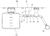
図1および図2に示すように、仮設トイレシステム100は、たとえば地震等の災害が発生した際に避難場所となる学校や公園等の避難区域の地中に施工される仮設トイレ用配管を含み、この仮設トイレ用配管は、複数のマンホール102、およびそれらと連通する第1排水管104を備えている。そして、災害が発生した際には、地上の所定位置に便器106や仮設小屋108を取り付けることにより、この仮設トイレシステム100を仮設トイレとして使用することが可能である。
As shown in FIGS. 1 and 2, the
マンホール102は、予め定めた便器106の設置位置に対応させて地中に埋設されている。なお、図1および図2では、4つのマンホール102を等間隔に並べて配置しているが、これは単なる例示であり、マンホール102の配置個数は、避難区域の広さ等に応じて適宜変更され得る。この4つのマンホール102は、それぞれ同等のものであり、たとえば硬質塩化ビニル製のリブ付き小型マンホールであって、その径は、たとえば300mmである。
The
マンホール102の側壁の最下部には、流入部110と流出部112とがほぼ同一の管軸に沿ってほぼ一直線上に形成されている。流入部110および流出部112は、ともに短円筒形状の受口構造であって、ここにそれぞれ上流側ないし下流側の第1排水管104が挿入されてゴム輪接合される。
In the lowermost part of the side wall of the
また、マンホール102の上端部には、鉛直上方に向かって開口するゴム輪受口114が形成されており、このゴム輪受口114には、鉛直上方に立ち上がる縦管116が接合される。縦管116の長さ寸法は、マンホール102の設置深さに応じて適宜調整され、上流側のマンホール102に接続されたものほど小さくなるようにされている。さらに、縦管116の上側開口部は内蓋(図示せず)によって閉じられており、その上側開口部の外側(周囲)には、台座および受枠を介して防護蓋が設置され、この防護蓋118の上面が地表面200に臨んでいる。
Further, a rubber
このようにして、各マンホール102が第1排水管104を介して接続されている。第1排水管104は、たとえば硬質塩化ビニル製のリブ付き管であり、所定の下り勾配(たとえば18/1000程度)を付けて配設され、各マンホール102の内部と連通した排水管路を形成する。
In this way, the
さらに、第1排水管104よりも上流側には、第1排水管104の上流側へ仮設トイレの洗浄用水を送り込む送水手段として、貯水タンク120が設置される。具体的には、貯水タンク120は、最上流側に配置されたマンホール102の流入部110に接続された第1排水管104とゲート弁122を介して接続される。貯水タンク120には、たとえば給水ポンプ(図示せず)から水が供給され、ゲート弁122を閉じることによって、供給された水を貯水タンク120の内部に留めておき、ゲート弁122を開くことによって、この貯水タンク130内に溜められた水を第1排水管104の上流側の管端へ送り込む。
Further, a
さらにまた、第1排水管104の下流側には、上述した枡10を介して、第2排水管124および第3排水管126が接続されている。具体的には、図1および図3に示すように、枡10の流入口14に、第1排水管104の下流側の端部が接続され、枡10の一方の流出口(第1流出口)16に、第2排水管124の上流側の端部が接続され、枡10の他方の流出口(第2流出口)18に、第3排水管126の上流側の端部が接続される。
Furthermore, the
第2排水管124は、枡10の第1流出口16から流出した排水を公共枡128を通じて既設の下水管(公共下水道)130まで送る管路であって、複数の直管、可撓管および継手などを適宜連結して形成される。
The
また、第3排水管126は、枡10の第2流出口18から流出した排水を貯留槽132まで送る管路であって、複数の直管、可撓管および継手などを適宜連結して形成される。貯留槽132は、たとえばレジンコンクリートによって形成され、災害時などには、各マンホール102に溜まった汚物を含む排水を貯留するために用いられる。また、災害時以外の時には(つまり、貯留槽128を使用する前の状態では)、図示しないゲート弁などによって内部の空間を水密的に密閉しており、上述した便器106や仮設小屋108などの備品を収容するケーシングとして好適に兼用される。
The
以上で、枡10を流路切り替え装置として用いた仮設トイレシステム100について説明した。
In the above, the
以下に、このような仮設トイレシステム100を前提にして、必要に応じてそれらを援用しながら、本発明の実施例または実施形態について説明する。
Hereinafter, on the assumption of such a
図4および図5に示すように、枡10は、塩化ビニルなどの合成樹脂からなり、上述したように、1つの流入口14と2つの流出口16,18とを有する枡本体12とインバートブロック20とを備えている。
As shown in FIGS. 4 and 5, the
なお、この発明では、2つの流出口16,18を第1流出口16と第2流出口18として使い分け、それぞれ異なる排水管との接続部として利用しているが、説明の際にこれらを区別する必要がない場合には、単に流出口16,18と記載することに留意されたい。
In the present invention, the two
枡本体12は、側壁22および底板24からなり、有底円筒状に形成され、側壁22の上端部には、鉛直上方に向かって開口する点検口26が形成されている。側壁22の径は、たとえば300mmであり、その上下方向の長さ(つまり、高さ)は、たとえば1000mmである。
The
枡本体12の側壁22には、短円筒状に外側に突き出す1つの流入部28が形成されている。流入部28は、受口構造を有しており、ここに上述した第1排水管104が挿入される。たとえば、流入部28の内面には、ゴム溝が形成されており、そのゴム溝に装着されたゴム輪(図示せず)によって第1排水管104との接合部が密封されている。流入部24は、上流側に位置する第1排水管104の端部と接続される接続部であるとともに、その開口が上流側から枡10内に排水を流入させる流入口14として用いられる。流入口14の径は、たとえば150mmである。
A
さらに、枡本体12の側壁22には、短円筒状に外側に突き出す第1および第2流出部30,32がそれぞれ形成されている。第1および第2流出部30,32は、各々が流入口14の軸線と直交または略直交し、かつ同一の管軸に沿ってほぼ一直線上に形成されている。
Further, first and
第1流出部30は、差口構造を有しており、上述した第2排水管124の端部の継手等に挿入されて、接着接合等される。第1流出部30は、下流側に位置する第2排水管124の端部に接続される接続部であるとともに、その開口が枡10内の排水を下水管130に流出させる第1流出口16として用いられる。第1流出口16の径は、たとえば150mmである。
The
また、第2流出部32は、差口構造を有しており、上述した第3排水管126の端部の継手等に挿入されて、接着接合等される。第2流出部32は、下流側に位置する第3排水管126の端部が接続される接続部であるとともに、その開口が枡10内の排水を貯留槽132に流出させる第2流出口18として用いられる。第2流出口18の径は、たとえば150mmである。
Moreover, the
さらに、枡本体12内の底部、つまり底板24の上側には、インバートブロック20が設置されている。
Further, an
図6および図7に示すように、インバートブロック20は、塩化ビニル等の合成樹脂やゴム等の材料からなり、枡本体12の内側形状(内形)に適合する外側形状(外形)を有するブロック本体34を含む。たとえば、この実施例では、ブロック本体34は、枡本体12の側壁22の内径とほぼ等しい外径の円柱状に形成され、その下面が底板24の上面に密着し、かつその外面が側壁22の内面に密着するように設置されている(図5参照)。
As shown in FIGS. 6 and 7, the
さらに、ブロック本体34の上面には、インバート溝36が形成されている。インバート溝36は、断面形状がほぼ半円形の溝であり、流入口14および流出口16,18の下半分の形状と適合する形状を有している。インバート溝36は、インバートブロック20を所定の向き(周方向位置)で設置した時に、その長手方向の両端部が流入口14と第1および第2流出口16,18のいずれか一方とに連なるように(形状に)されており、流入口14と第1および第2流出口16,18のいずれか一方とを連通する流路を形成する。
Further, an
たとえば、この実施例では、枡本体12の流入口14と各流出口16,18とを互いに直交するように形成しているので、インバート溝36は、その長手方向において、ブロック本体34の周縁の一方端部からブロック本体34の周縁の他方端部に向けて約90°湾曲する弧状に形成されている。
For example, in this embodiment, since the
また、インバートブロック20は、枡本体12内で周方向に回動自在に設置されており、インバートブロック20を回動させて、インバートブロック20の周方向位置を変えることによって、流入口14から枡本体12内に流入した排水の流出先を第1および第2流出口16,18のいずれか一方に切り替えることが可能である。すなわち、インバートブロック20の周方向位置によって排水の流出先が規定され、流入口14から枡本体12内に流入した排水をインバート溝36を通して第1および第2流出口16,18のいずれか一方に選択的に流出させることができる。
The
具体的には、インバートブロック20を、そのインバート溝36の長手方向の両端部が流入口14および第1流出口16と連なる周方向位置にセット(設置)した第1状態と、インバートブロック20を、そのインバート溝36の長手方向の両端部が流入口14および第2流出口18と連なる周方向位置にセットした第2状態とに切り替えることができ、図8(a)に示すように、インバートブロック20を第1状態で設置している時には、流入口14から枡本体12内に流入した排水が第1流出口16に流出されることとなり、図8(b)に示すように、インバートブロック20を第2状態で設置している時には、流入口14から枡本体12内に流入した排水が第2流出口18に流出されることとなる。
Specifically, the
したがって、このような枡10を仮設トイレシステム100において流路切り替え装置として用い、下水管130の状況に応じて、枡10内に流入した排水の流出先を第1および第2流出口16,18のいずれか一方に選択的に切り替えることによって、各マンホール102内に溜まった汚物を含む排水の処理先を選択することが可能である。
Therefore,
以下には、図1および図8を参照して、仮設トイレシステム100を利用した仮設トイレにおいて、下水管130を使用可能な通常時に、各マンホール102内に溜まった汚物を含む排水を処理する方法について具体的に説明する。
In the following, referring to FIG. 1 and FIG. 8, in a temporary toilet using the
先ず、枡本体12内の底部に設置されたインバートブロック20を回動させて、インバートブロック20をそのインバート溝36の長手方向の両端部が流入口14および第1流出口16と連なった第1状態でセットして、第1排水管104と第2排水管124とを連通させておく。
First, the
なお、枡本体12内の底部に設置されたインバートブロック20を回動させる方法としては、インバートブロック20の上面に図示しない孔などを設け、その孔に差し込んだ棒などを作業員の手作業によって回転させる方法などが考えられるが、特に限定されるものではない。
In addition, as a method of rotating the
続いて、各マンホール102内に溜まった汚物を洗浄(掃流)するための洗浄用水を貯水タンク120に給水し、ゲート弁122を適宜のタイミングで開いて、貯水タンク130内に溜まった水のうち所定量の水を第1排水管104の上流側の管端に流入させる。ゲート弁72を開くタイミングや貯水タンク130から送り込む水の量は、各マンホール102内に溜められた汚物を、比較的少ない水を使用して掃流させることができるように適宜調整する。
Subsequently, cleaning water for cleaning (scavenging) the filth collected in each
すると、第1排水管104を流下する水とともに各マンホール102内に溜まった汚物が、所定の勾配で埋設されている第1排水管104を所定の速度で流下し、各マンホール102内に溜まった汚物を含む排水が、第1排水管104の下流側の端部から枡10内に導かれる。
Then, the filth collected in each
そして、流入口14から枡本体12内に流れ込んだ排水が、インバート溝36を通って第1流出口16から第2排水管124に流れ込み、第2排水管124を通って下水管130に排出されることとなる。
Then, the wastewater that has flowed into the dredge
次に、下水管130が被災するなどして使用できなくなった(機能しなくなった)時に各マンホール102内に溜まった汚物を含む排水を処理する方法について具体的に説明する。
Next, a specific description will be given of a method of treating wastewater containing filth collected in each
先ず、枡本体12内の底部に設置されたインバートブロック20を回動させて、インバートブロック20をそのインバート溝36の長手方向の両端部が流入口14および第2流出口18と連なった第2状態でセットし、第1排水管104と第3排水管126とを連通させておく。
First, the
続いて、上述したのと同じ要領で、各マンホール102内に溜まった汚物を洗浄するための洗浄用水を貯水タンク120に給水し、ゲート弁122を適宜のタイミングで開いて、貯水タンク130内に溜まった水のうち所定量の水を第1排水管104の上流側の管端に流入させる。
Subsequently, in the same manner as described above, cleaning water for cleaning the filth accumulated in each
すると、第1排水管104を流下する水とともに各マンホール102内に溜まった汚物が、所定の勾配で埋設されている第1排水管104を所定の速度で流下し、各マンホール102内に溜まった汚物を含む排水が、第1排水管104の下流側の端部から枡10内に導かれる。
Then, the filth collected in each
そして、流入口14から枡本体12内に流れ込んだ排水が、インバート溝36を通って第2流出口18から第3排水管126に流れ込み、第3排水管126を通って貯留槽132の内部に排出され、そのまま貯留槽132の内部に貯留される。
Then, the wastewater that has flowed into the
その後、下水管130が復旧した時などに、貯留槽132の上部の点検口などから貯留槽132の内部にバキュームカーの吸込ホースなどを差し込んで、その吸込ホースによってバキュームカーの収集タンクの中などに回収する。
After that, when the
以上のように、この実施例の枡10では、流入口14から枡本体12内に流入した排水の流出先を第1および第2流出口16,18のいずれか一方に選択的に切り替えることが可能である。したがって、このような枡10を仮設トイレシステム100において流路切り替え装置として用いるようにすれば、下水管130の状況に応じて、各マンホール102内に溜まった汚物を含む排水の処理先を選択することが可能になる。
As described above, in the
すなわち、下水管130を使用可能な時には、枡10のインバートブロック20を第1状態で設置して、第1排水管104と第2排水管124とを連通させておくことにより、各マンホール102内に溜まった汚物を含む排水を下水管130に直接排出することが可能である。一方、下水管130を使用することができない時には、インバートブロック20を第2状態で設置し(第2状態に切り替えて)、第1排水管104と第3排水管126とを連通させておくことにより、各マンホール102内に溜まった汚物を含む排水を貯留槽132の内部に排出して、貯留槽132内に一時的に貯留しておくことが可能である。
That is, when the
したがって、この実施例によれば、地震等の災害時に下水管130が使用できなくなった場合であっても、仮設トイレなどの排水設備を使用可能にすることができるようになる。
Therefore, according to this embodiment, even when the
なお、上述の実施例では、インバートブロック20のブロック本体34が、枡本体12の側壁22の内径とほぼ等しい外径の円柱状に形成され、その下面が底板24の上面に密着し、かつその外面が枡本体12の側壁20の内面に密着したが、これに限定される必要はない。図示は省略するが、ブロック本体34の側面や下面に凹凸を設けることにより、ブロック本体34の側面や下面と枡本体12の内面(側壁22の内面、底板24の上面)とが接する面積を小さくして、インバートブロック20の回動時の摩擦力を低減させるようにしてもよい。
In the above-described embodiment, the block
また、上述の実施例では、枡10の流入部28が受口構造を有していて、そこに第1排水管104が挿入されるとともに、枡10の第1および第2流出部30,32が差口構造を有していて、そこが第2排水管126ないし第3排水管128の端部の継手等に挿入されて、接着接合等されたが、これに限定される必要はない。枡10の流入部28ならびに第1および第2流出部30,32は、あくまで各排水管104,126,128との接続部であればよく、受口構造であっても差口構造であってもよい。
Moreover, in the above-mentioned Example, the
さらに、上述の実施例では、インバート溝36は、断面形状がほぼ半円形の溝であり、流入口14および流出口16,18の下半分の形状と適合する形状を有してたが、これに限定される必要はない。流入口14から枡10内に流入した排水をインバート溝36を通して流出口16,18に流出させることができるのであれば、インバート溝36の形状は特に限定されない。なお、ブロック本体34の上面にインバート溝36を形成するようにすると、インバートブロック20の周方向位置が正しいかどうかを、たとえば点検口26から目視確認することができるため、好適である。
Further, in the above-described embodiment, the
さらにまた、図9に示すこの発明の他の実施例の枡10では、枡10のインバートブロック20を正確かつ簡単に第1状態や第2状態で設置できるように、インバートブロック20が回動する範囲を規制する規制手段が設けられる。以下、先の実施例と同様の部分については、同じ参照番号を用い、その説明を省略或いは簡略化する。
Furthermore, in the
図10に示すように、枡本体12内の底板24上の所定位置には、突起状のストッパ38が形成される。たとえば、この実施例では、ストッパ38は、側壁22の内面に沿うように底板24の周縁部に形成され、流入口14の位置に対向する位置に配置される。
As shown in FIG. 10, a protruding
また、図11および図12に示すように、インバートブロック20のブロック本体34の底面には、ストッパ38を収容可能な形状に窪ませた窪み部40が形成される。窪み部40は、断面形状がストッパ38の断面とほぼ同じ形状であって、かつ長手方向がブロック本体34の側面に沿って湾曲する窪み(溝)であり、インバートブロック20を枡本体12内に設置した時には、窪み部40の内部にストッパ38が収容される。そして、窪み部40の内部にストッパ38を収容した状態でインバートブロック20を回動させるようにすると、インバートブロック20の窪み部40の長手方向の端部にストッパ38が当たる(当接する)ことにより、インバートブロック20の回動範囲が規制される。
Further, as shown in FIGS. 11 and 12, a recessed
窪み部40は、その長手方向の一方端部にストッパ38が当たった時にインバートブロック20を第1状態で設置でき、かつその長手方向の他方端部にストッパ38が当たった時にインバートブロック20を第2状態で設置できることができるように、所定の形状に形成されている。
The
たとえば、この実施例では、枡本体12の流入口14と流出口16,18とが互いに直交するように形成されていて、流入口14に対向する位置にストッパ38が形成されているので、窪み部40は、約90°の範囲で湾曲する弧状に形成されており、その長手方向の一方端部がインバート溝36の長手方向の一方端部と対向する位置に配置され、かつその長手方向の他方端部がインバート溝36の長手方向の他方端部と対向する位置に配置されている。
For example, in this embodiment, the
このような枡10では、図9(a)に示すように、インバートブロック20をその窪み部40の一方端部にストッパ38が当たるまで回動させて、その周方向位置にセットすることにより、インバートブロック20が第1状態で設置されて、流入口14と第1流出口16とが連通される。また、図9(b)に示すように、インバートブロック20をその窪み部40の長手方向の他方端部にストッパ38が当たるまで回転させて、その周方向位置にセットすることにより、インバートブロック20が第2状態で設置されて、流入口14と第2流出口18とが連通される。
In such a
このように、この実施例によれば、インバートブロックが回動する範囲を規制手段によって規制して、インバートブロック20をその窪み部40にストッパ38が当たるまで回動させた時に、インバートブロック20が所定の周方向位置に位置決めされるようにしているので、インバートブロック20を正確かつ簡単に第1状態ならびに第2状態で設置することができるようになる。
As described above, according to this embodiment, when the range in which the invert block rotates is regulated by the regulating means, the
なお、この実施例では、枡本体12内の底板24上に突起状のストッパ38が形成され、インバートブロック20のブロック本体34の底面に、ストッパ38を収容可能な形状の窪み部40が形成されたが、これに限定される必要はない。
In this embodiment, a protrusion-
たとえば、枡本体12の側壁22の内面に突起状のストッパを形成するとともに、インバートブロック20のブロック本体34の側面に窪み部を形成するようにしてもよいし、また、枡本体12の内面に窪み部を形成するとともに、インバートブロック20のブロック本体34の外面に突起状のストッパを形成するようにしてもよい。さらにまた、枡本体12の内面に第1ストッパを形成するとともに、インバートブロック20のブロック本体34の外面に第1ストッパと係止する第2ストッパを設けるようにしてもよい。
For example, a protrusion-like stopper may be formed on the inner surface of the
要は、インバートブロックの回動範囲を規制手段によって規制して、インバートブロック20をその規制手段に規制されるまで回動させた時に、インバートブロック20が所定の周方向位置に位置決めされるようにすることができるのであれば、規制手段は特に限定されない。
In short, when the rotation range of the invert block is restricted by the restriction means and the
さらにまた、この発明の他の実施例の枡10では、枡本体12内に図13に示すインバートブロック20が設置され、インバートブロック20が枡本体12の点検口26から操作部材46によって上下方向に移動可能かつ周方向に回動可能にされる。以下、先の実施例と同様の部分については、同じ参照番号を用い、その説明を省略或いは簡略化する。
Furthermore, in the
図13に示すように、インバートブロック20のブロック本体34の上面には、立ち上がり部42が一体的に形成される。立ち上がり部42は、枡本体12の側壁22の内面に沿う円筒状に形成され、ブロック本体34の周縁部から円筒状に立ち上がり、その外面がブロック本体34の側面と連続している。
As shown in FIG. 13, a rising
立ち上がり部42の上端開口縁には、立ち上がり部42の直径方向において対峙する2点に切り欠きが形成され、それらの切り欠きが装着部44として利用される。装着部44は、後述する操作用部材46を装着するための部位であり、この装着部44と操作用部材46とが、インバートブロック20を枡本体12の点検口26から上下方向に移動可能かつ周方向に回動可能に操作する操作手段として機能する。
Cutouts are formed at two points facing each other in the diameter direction of the rising
装着部44は、立ち上がり部42の上端開口縁から下方に延びる第1装着部44aと、第1装着部44aの下端から直交して立ち上がり部42の周方向に延びる第2装着部44bと、第2装着部44bの端部から直交して上下方向に延びる第3装着部44cとによって構成され、図14に示すように、2つの装着部44が立ち上がり部42の中心を定点としてほぼ点対称に形成される。
The mounting
なお、2つの装着部44のうち一方は、第3装着部44cがインバート溝36の長手方向の端部の鉛直上方向に位置するように形成される。こうすることにより、後述する操作用部材46を第3装着部44cに配置した時に、操作用部材46の向きを枡本体12の流入口14ないし流出口16,18の位置に合わせることによって、インバートブロック20を適正な周方向位置に(つまり、第1状態ないし第2状態で)設置できているか否かの目安にすることができるようになる。
Note that one of the two mounting
また、図15に示すように、操作用部材46は、塩化ビニルなどの合成樹脂からなる長尺部材である。操作用部材46は、枡本体12の側壁22の上下方向の長さ管長に対応する長さの筒状に形成される縦部材48aと、立ち上がり部42の外径と略等しい長さの筒状に形成されて縦部材48の上端部に設けられる上側横部材48bと、立ち上がり部42の外径と略等しい長さの筒状に形成されて縦部材48の下端部に設けられる下側横部材48cとからなり、略I字形状を有している。
As shown in FIG. 15, the
このような枡10では、インバートブロック20を枡本体12内へ設置する時には、図16(a)に示すように、操作用部材46の下側横部材48cを第1装着部44aに通す。それから、第2装着部44bを通して、図16(b)に示すように、第3装着部44cの下部に装着し、その状態で操作用部材46を枡本体12の点検口26に挿入して下方向に押し込むことによって、インバートブロック20を枡本体12の底板24上に載置する。
In such a
また、インバートブロック20を回動させて、インバートブロック20を第1状態ないし第2状態で設置する(切り替える)時には、インバートブロック20の第3装着部44cの下部に操作用部材46の下側横部材48cを装着した状態で、操作用部材46の上側横部材48bを周方向に回動させることによってインバートブロック20を回動させて、インバート溝36の長手方向の両端部の位置を枡本体12の流入口14および流出口16,18の位置に合わせる。
Further, when the
さらに、インバートブロック20を取り外す際には、インバートブロック20の第3装着部44cの上部に操作用部材46の下側横部材48cを装着した状態で、操作用部材46を上方向に持ち上げることによってインバートブロック20を上方向に移動させて、インバートブロック20を枡本体12の点検口26などから外部に取り出す。
Further, when the
このように、この実施例では、インバートブロック20の装着部44に操作用部材46を装着して、枡本体12の点検口26から操作用部材46を操作することによって、インバートブロック20を上下方向に移動かつ周方向に回動させることが可能である。したがって、インバートブロック20を設置し、所定の周方向位置に回動させる作業や、インバートブロック20を取り外す作業を簡単に行うことができ、作業性に優れる。
As described above, in this embodiment, the operating
さらに、たとえばインバートブロック20のインバート溝36などに異物が詰まった場合にも、枡本体12からインバートブロック20を簡単に取り外して、異物を除去することが可能であるので、枡10の維持管理性が向上する。
Furthermore, for example, even when foreign matter is clogged in the
なお、上述の実施例では、インバートブロック20のブロック本体34の上面に、枡本体12の側壁22の内面に沿う円筒状の立ち上がり部42が形成され、その立ち上がり部42の上端開口縁に装着部44が形成されたが、これに限定される必要はない。
In the above-described embodiment, a cylindrical rising
たとえば、必ずしも立ち上がり部42の上端開口縁に装着部44を形成する必要はなく、上端開口縁に装着部44を有しない立ち上がり部42を形成するようにしてもよい。この場合であっても、インバートブロック20の設置時などに、立ち上がり部42が枡本体12の側壁22の内面に沿うことにより、枡本体12内でインバートブロック20の転び等が生じることを防止できるようになる。
For example, the mounting
また、必ずしも立ち上がり部42を枡本体12の側壁22の内面に沿う円筒状に形成する必要はなく、立ち上がり部42の形状はこの発明の趣旨を逸脱しない範囲で適宜変更するようにしてもよい。また、装着部44や操作用部材45の形状も、この発明の趣旨を逸脱しない範囲で適宜変更するようにしてもよい。
In addition, the rising
さらに、ブロック本体34の上面に立ち上がり部42を形成せずに、ブロック本体34の上面に直接、装着部44を設けるようにしてもよい。
Further, the mounting
ところで、上述の各実施例ではいずれも、枡10内にインバートブロック20を設置し、そのインバートブロック20を回動させて第1状態ないし第2状態で設置する(切り替える)ことによって、流入口14から枡本体12内に流入した排水の流出先を第1および第2流出口16,18のいずれか一方に選択的に切り替えるようにした。
By the way, in any of the above-described embodiments, the
しかしながら、これに限定される必要はない。要は、枡10が流入口14から枡本体12内に流入した排水の流出先を第1および第2流出口16,18のいずれか一方に切り替える切り替え手段を備えているのであればよく、その切り替え手段には、任意の方法を採用することができる。
However, it is not necessary to be limited to this. In short, it is sufficient if the
たとえば、図17および図18に示すこの発明のさらに他の実施例の枡10では、枡本体12の内部にインバートブロック20が設けられる代わりに、枡本体12の底板24にインバート50が形成され、そのインバート50に閉塞部材52が設けられる。以下、先の実施例と同様の部分については、同じ参照番号を用い、その説明を省略或いは簡略化する。
For example, in the
図17および図18に示すように、枡10は、塩化ビニルなどの合成樹脂からなり、1つの流入口14と2つの流出口16,18とを有する枡本体12を備えている。枡本体12は、側壁22および底板24からなり、有底円筒状に形成され、側壁22の上端部には、鉛直上方に向かって開口する点検口26が形成されている。
As shown in FIGS. 17 and 18, the
枡本体12の側壁22には、短円筒状に外側に突き出す1つの流入部28が形成されている。流入部28は、受口構造を有しており、上流側に位置する第1排水管102の端部と接続される接続部であるとともに、その開口が上流側から枡10内に排水を流入させる流入口14として用いられる。
A
さらに、枡本体12の側壁22には、短円筒状に外側に突き出す第1および第2流出部30,32がそれぞれ形成されている。第1流出部30は、差口構造を有しており、流入口14と同一の管軸に沿ってほぼ一直線上に形成され、下流側に位置する第2排水管124の端部に接続される接続部であるとともに、その開口が枡10内の排水を下水管130に流出させる第1流出口16として用いられる。また、第2流出部32は、差口構造を有しており、流入口14および第1流出口16の軸線と直交または略直交する位置に形成され、下流側に位置する第3排水管126の端部が接続される接続部であるとともに、その開口が枡10内の排水を貯留槽132に流出させる第2流出口18として用いられる。
Further, first and
さらに、枡本体12内の底部、つまり底板24の上側には、インバート50が一体的に形成されている。図19および図20に示すように、インバート50は、断面形状がほぼ半円形の溝であり、流入口14および各流出口16,18の下半分の形状と適合する形状を有している。インバート50は、流入口14から底板24の中心部に向かう第1インバート部50aと、第1流出口16から底板24の中心部に向かう第2インバート部50bと、第2流出口18から底板24の中心部に向かう第3インバート部50cとを含み、平面視で略T字形状を有している。このインバート50では、第1インバート部50aと第2インバート部50bとが連なって、流入口14と第1流出口16とを連通する第1流路を形成するとともに、第1インバート部50aと第3インバート部50cが連なって、流入口14と第2流出口18とを連通する第2流路を形成している。
Further, an
また、図17および図18に戻って、枡本体12内の底部のインバート50には、閉塞部材52が設置される。
Returning to FIG. 17 and FIG. 18, a closing
閉塞部材52は、図21および図22に示すように、塩化ビニルなどの合成樹脂からなり、インバート50の断面形状に適合する形状の閉塞部54を含み、閉塞部材42をインバート50へ設置した時には、この閉塞部54がインバート50に嵌め込まれて、流路を塞ぐ。また、閉塞部54の外側、つまり枡本体12の側壁22側には、当たり部56が一体的に形成される。当たり部56は、枡本体12の側壁22の内面に沿うように湾曲する板状に形成され、閉塞部材42をインバート50へ設置した時には、この当たり部56を枡本体12の側壁22の内面に沿わせることによって、閉塞部材52の位置を安定させる。
As shown in FIGS. 21 and 22, the closing
このような枡10では。図23(a)および(b)に示すように、枡本体12のインバート50の第2インバート部50bおよび第3インバート部50cのいずれか一方に閉塞部材52を設置することにより、閉塞部材52を設置したインバート部が第1インバート部50aとともに形成している流路が閉塞されて、残りの(もう一方の)インバート部が第1インバート部50aとともに形成している流路が開通されることとなる。
In such a
すなわち、閉塞部材52を設置するインバート部を切り替えることによって排水の流出先が規定され、流入口14から枡本体12内に流入した排水を第1および第2流出口16,18のいずれか一方に選択的に流出させることができる。
That is, the outflow destination of the waste water is defined by switching the invert portion where the blocking
具体的には、閉塞部材52を第3インバート部50cにセット(設置)した第1状態と、閉塞部材52を第2インバート部50bにセットした第2状態とに切り替えることができ、図23(a)に示すように、閉塞部材52を第3インバート部50cに設置して、流入口14と第1流出口16とを連通する第1流路を開通させた第1状態では、流入口14(第1排水管104)から枡本体12内に流入した排水が第1流出口16(第2排水管124)に流出されることとなり、図23(b)に示すように、閉塞部材52を第2インバート部50bに設置して、流入口14と第2流出口18とを連通する第2流路を開通させた第2状態では、流入口14(第1排水管104)から枡本体12内に流入した排水が第2流出口18(第2排水管126)に流出されることとなる。
Specifically, it is possible to switch between a first state in which the closing
以上のように、この実施例においても、図1の実施例と同様に、流入口14から枡本体12内に流入した排水の流出先を第1および第2流出口16,18のいずれか一方に切り替えることが可能である。したがって、この枡10を仮設トイレシステム100に適用することによって、下水管130の状況に応じて、各マンホール102内に溜まった汚物を含む排水の処理先を選択することができるようになる。
As described above, also in this embodiment, as in the embodiment of FIG. 1, the drainage destination of the wastewater that has flowed into the tub
すなわち、下水管130を使用可能な時には、枡10の閉塞部材52をインバート50の第3インバート部50cにセットして(第1状態にして)、第1排水管104と第2排水管124とを連通させておくことにより、各マンホール102内に溜まった汚物を含む排水を下水管130に直接排出することが可能である。一方、下水管130を使用することができない時には、閉塞部材52をインバート50の第2インバート部50bにセットして(第2状態に切り替えて)、第1排水管104と第3排水管126とを連通させておくことにより、各マンホール102内に溜まった汚物を含む排水を貯留槽132の内部に排出して、貯留槽132内に一時的に貯留しておくことが可能である。
That is, when the
したがって、この実施例においても、地震等の災害時に下水管130が使用できなくなった場合であっても、仮設トイレなどの排水設備を使用可能にすることができるようになる。
Therefore, also in this embodiment, even when the
なお、この実施例では、1つの閉塞部材52を第2インバート部50bおよび第3インバート部50cのいずれかに付け替えることによって、流入口14から枡本体12内に流入した排水の流出先を第1および第2流出口16,18のいずれか一方に切り替えるようにしたが、これに限定される必要はない。
In this embodiment, by replacing one closing
たとえば、予め閉塞部材52を第2インバート部50bおよび第3インバート部50cのそれぞれに設置しておき、使用する流路に応じてその流路を塞ぐ閉塞部材52を取り外すようにしてもよい。こうすることにより、臭気等の枡10内への侵入を防止することが可能になる。
For example, the closing
また、閉塞部54を上下動可能に形成した閉塞部材52を第2インバート部50bおよび第3インバート部50cのそれぞれに設置し、当たり部56を側壁22の内面に固定しておき、使用する流路に応じてその流路を塞ぐ閉塞部材52の閉塞部54を上側に動かして流路を開放するようにしてもよい。
Further, the closing
さらにまた、この実施例の枡10の閉塞部材52に立ち上がり部60を形成し、閉塞部材52を枡本体12の点検口26から操作部材46によって付け替えるようにしてもよい。
Furthermore, the rising
図24および図25に示すように、閉塞部材52の当たり部56の上側には、立ち上がり部58が形成される。立ち上がり部58は、当たり部56と一体的に形成され、当たり部56からそのまま円筒状に立ち上がり、その外面が当たり部56の外面と連続している。
As shown in FIGS. 24 and 25, a rising
立ち上がり部58の上端開口縁には、立ち上がり部58の直径方向において対峙する2点に装着部60が形成される。装着部60は、立ち上がり部58の上端開口縁から下方に延びる第1装着部60aと、第1装着部60aの下端から直交して立ち上がり部58の周方向に延びる第2装着部60bと、第2装着部60bの端部から直交して上下方向に延びる第3装着部60cとによって構成される。
At the upper end opening edge of the rising
このような枡10では、閉塞部材52をインバート50のインバート部へ設置する時に、閉塞部材52の立ち上がり部58の装着部60の第3装着部60cに上述した操作用部材46を装着し、操作用部材46を枡本体12の点検口26から操作して、閉塞部材52をインバート50のインバート部へ嵌め込んで、一方の流路を閉塞させる。そして、閉塞部材52を他のインバート部へ設置する(つまり、付け替える時)には、閉塞部材52の第3装着部60cの上部に操作用部材46を装着した状態で、操作用部材46を持ち上げて閉塞部材52をインバート50のインバート部から取り外し、そのまま他のインバート部に設置するようにする。
In such a
なお、上の説明では、本発明の枡10を仮設トイレシステム100に適用し、そこで枡10を仮設トイレ用配管から流出する排水の排出先を選択する流路切り替え装置としてとして用いるようにしたが、これに限定される必要はない。たとえば、仮設トイレ用配管とその最下流に配置された簡易貯留槽とに初期水を貯留し、所定時間ごとに簡易貯留槽の底部開口部を開放することで初期水とともに汚物を下水管に排出するタイプの仮設トイレシステムに本発明の枡10を適用し、そこで枡10を簡易貯留槽から排出される排水の排出先を選択する流路切り替え装置として用いるようにしてもよい。
In the above description, the
また、必ずしも本発明の枡10を仮設トイレシステムにおける流路切り替え装置として用いる必要もなく、既設下水管(公共下水道)を利用した排水設備であれば、仮設トイレ以外の排水設備においても流路切り替え装置として好適に用いることができる。
In addition, it is not always necessary to use the
さらにまた、仮設トイレシステムにおいても、必ずしも流路切り替え装置として本発明の枡10を利用する必要はなく、流路切り替え装置として三方弁などを利用するようにしてもよいし、流路切り替え装置の2つの流出口のそれぞれに仕切り弁を設けることによって排水の排出先を選択する(切り替える)ようにしてもよい。
Furthermore, in the temporary toilet system, it is not always necessary to use the
さらに、上述した寸法等の具体的数値は、いずれも単なる一例であり、製品の仕様などの必要に応じて適宜変更可能である。 Furthermore, the specific numerical values such as the dimensions described above are merely examples, and can be appropriately changed according to the needs of the product specifications and the like.
10 …枡
12 …枡本体
14 …流入口
16 …第1流出口
18 …第2流出口
20 …インバートブロック
38 …ストッパ
40 …窪み部
42 …立ち上がり部
50 …インバート
52 …閉塞部材
100 …仮設トイレシステム
104 …第1排水管
124 …第2排水管
126 …第3排水管
130 …下水管
132 …貯留槽
DESCRIPTION OF
Claims (8)
予め定めた便器の設置位置の地中に埋設される複数の縦管部材、
各縦管部材に接続され、所定の勾配で配設される第1排水管、
前記第1排水管の下流側に設けられ、1つの流入口と2つの流出口とを有しかつ排水の流出先を2つの流出口のいずれか一方に選択的に切り替える流路切り替え装置、
前記流路切り替え装置の一方の流出口に接続され、その下流側が既設下水管に接続される第2排水管、および
前記流路切り替え装置の他方の流出口に接続され、その下流側が貯留槽に接続される第3排水管を備え、
前記既設下水管を使用可能な時には、前記流路切り替え装置により前記排水の流出先を前記一方の流出口に切り替えて、前記排水を前記第2排水管を介して前記既設下水管に排出し、前記既設下水管が使用できない時には、前記流路切り替え装置により前記排水の流出先を前記他方の流出口に切り替えて、前記排水を前記第3排水管を介して前記貯留槽の内部に貯留する、仮設トイレシステム。 A temporary toilet system that is used as a temporary toilet with a toilet attached in a disaster,
A plurality of longitudinal pipe members embedded in the ground of the installation position of a predetermined toilet;
A first drain pipe connected to each longitudinal pipe member and disposed at a predetermined gradient;
A flow path switching device that is provided on the downstream side of the first drain pipe and has one inflow port and two outflow ports, and selectively switches the outflow destination of drainage to one of the two outflow ports,
Connected to one outlet of the channel switching device, the second drain pipe connected downstream to the existing sewer pipe, and connected to the other outlet of the channel switching device, the downstream side serving as a storage tank A third drain pipe connected,
When the existing sewer pipe can be used, the flow path switching device switches the drainage destination of the drainage to the one outlet, and the drainage is discharged to the existing sewer pipe through the second drainage pipe, When the existing sewer pipe cannot be used, the drainage destination of the drainage is switched to the other outlet by the flow path switching device, and the drainage is stored in the storage tank via the third drainage pipe. Temporary toilet system.
前記枡は、
底面と側壁とを有する枡本体、
前記側壁に形成され、前記第1排水管の下流側の端部が接続される流入口、
前記側壁に形成され、前記第2排水管の上流側の端部が接続される第1流出口、
前記側壁に形成され、前記第3排水管の上流側の端部が接続される第2流出口、および
前記枡本体の内部に設けられ、前記流入口から前記枡本体の内部に流入する排水の流出先を前記第1および第2流出口のいずれか一方に切り替える切り替え手段を含む、請求項1記載の仮設トイレシステム。 The flow path switching device is a gutter embedded on the downstream side of the first drain pipe,
The bag is
A bag body having a bottom surface and side walls,
An inlet formed on the side wall, to which an end on the downstream side of the first drain pipe is connected;
A first outlet formed on the side wall and connected to an upstream end of the second drain pipe;
A second outlet formed on the side wall to which an upstream end of the third drain pipe is connected; and provided inside the dredge main body, for drainage flowing into the dredger main body from the inlet The temporary toilet system according to claim 1, further comprising switching means for switching an outflow destination to one of the first and second outlets.
前記インバートブロックを前記枡本体内で回動させることによって、前記排水の流出先を前記第1および第2流出口のいずれか一方に切り替える、請求項2記載の仮設トイレシステム。 The switching means of the rod includes an invert block installed on the bottom surface so as to be rotatable in the circumferential direction,
The temporary toilet system according to claim 2, wherein the inflow block is switched to one of the first and second outlets by rotating the invert block within the main body.
前記枡の前記切り替え手段は、前記インバートに設置して流路を塞ぐ閉塞部材を含み、
前記閉塞部材によって前記第1および第2流路のいずれか一方を塞ぐことによって、前記排水の流出先を前記第1および第2流出口のいずれか一方に切り替える、請求項2記載の仮設トイレシステム。 The trough further includes an invert provided on the bottom surface and forming first and second flow paths connecting from the inflow port to the first and second outflow ports, respectively.
The switching means of the heel includes a blocking member that is installed in the invert and closes the flow path,
The temporary toilet system according to claim 2, wherein the drainage destination is switched to one of the first and second outlets by closing one of the first and second flow paths with the blocking member. .
前記側壁に形成される流入口、
前記側壁に形成される第1および第2流出口、および
前記枡本体の内部に設けられ、前記流入口から前記枡本体の内部に流入する排水の流出先を前記第1および第2流出口のいずれか一方に切り替える切り替え手段を備える、枡。 A bag body having a bottom surface and side walls,
An inlet formed in the side wall,
First and second outlets formed in the side wall, and an outlet of drainage that is provided inside the dredge body and flows into the dredge body from the inflow port.枡 comprising switching means for switching to either one.
前記インバートブロックを前記枡本体内で回動させることによって、前記排水の流出先を前記第1および第2流出口のいずれか一方に切り替える、請求項5記載の枡。 The switching means includes an invert block installed on the bottom surface so as to be rotatable in the circumferential direction,
The scissors according to claim 5, wherein the drain destination of the drainage is switched to one of the first and second outlets by rotating the invert block within the scissors body.
前記切り替え手段は、前記インバートに設置して流路を塞ぐ閉塞部材を含み、
前記閉塞部材によって前記第1および第2流路のいずれか一方を塞ぐことによって、前記排水の流出先を前記第1および第2流出口のいずれか一方に切り替える、請求項5記載の枡。 An invert which is provided on the bottom surface and forms first and second flow paths from the inflow port to the first and second outflow ports,
The switching means includes a blocking member that is installed in the invert and closes the flow path,
The scissors according to claim 5, wherein the drainage destination of the drainage is switched to one of the first and second outlets by closing one of the first and second flow paths with the blocking member.
Priority Applications (1)
| Application Number | Priority Date | Filing Date | Title |
|---|---|---|---|
| JP2012182879A JP6068051B2 (en) | 2012-08-22 | 2012-08-22 | Temporary toilet system |
Applications Claiming Priority (1)
| Application Number | Priority Date | Filing Date | Title |
|---|---|---|---|
| JP2012182879A JP6068051B2 (en) | 2012-08-22 | 2012-08-22 | Temporary toilet system |
Publications (2)
| Publication Number | Publication Date |
|---|---|
| JP2014040723A true JP2014040723A (en) | 2014-03-06 |
| JP6068051B2 JP6068051B2 (en) | 2017-01-25 |
Family
ID=50393169
Family Applications (1)
| Application Number | Title | Priority Date | Filing Date |
|---|---|---|---|
| JP2012182879A Active JP6068051B2 (en) | 2012-08-22 | 2012-08-22 | Temporary toilet system |
Country Status (1)
| Country | Link |
|---|---|
| JP (1) | JP6068051B2 (en) |
Cited By (12)
| Publication number | Priority date | Publication date | Assignee | Title |
|---|---|---|---|---|
| JP2015145583A (en) * | 2014-02-03 | 2015-08-13 | アロン化成株式会社 | Drainage mass and drainage system equipped with it |
| JP2015183350A (en) * | 2014-03-20 | 2015-10-22 | 積水化学工業株式会社 | temporary toilet system |
| JP2017095969A (en) * | 2015-11-24 | 2017-06-01 | アロン化成株式会社 | Drainage mass and drainage system equipped with it |
| JP2017214709A (en) * | 2016-05-30 | 2017-12-07 | アロン化成株式会社 | Temporary toilet system |
| JP2018000580A (en) * | 2016-07-01 | 2018-01-11 | 有限会社四国浄管 | Temporary urinal |
| JP2018109321A (en) * | 2017-01-05 | 2018-07-12 | アロン化成株式会社 | Catch basin |
| JP2018204245A (en) * | 2017-06-01 | 2018-12-27 | アロン化成株式会社 | Catch basin |
| JP2019148140A (en) * | 2018-02-28 | 2019-09-05 | アロン化成株式会社 | Piping installation for temporary toilet |
| JP2019210757A (en) * | 2018-06-07 | 2019-12-12 | アロン化成株式会社 | Piping member |
| JP2020007877A (en) * | 2018-07-12 | 2020-01-16 | アロン化成株式会社 | Piping member |
| JP2021017794A (en) * | 2019-07-24 | 2021-02-15 | アロン化成株式会社 | Catch basin and drainage system |
| JP2023063727A (en) * | 2021-10-25 | 2023-05-10 | アロン化成株式会社 | Basin and drain piping system |
Citations (8)
| Publication number | Priority date | Publication date | Assignee | Title |
|---|---|---|---|---|
| JPH0447041A (en) * | 1990-06-13 | 1992-02-17 | Maezawa Kasei Kogyo Kk | Catch-basin |
| JPH07197514A (en) * | 1993-12-28 | 1995-08-01 | Takiron Co Ltd | Flow passage change type catch-basin |
| JPH07300897A (en) * | 1994-05-02 | 1995-11-14 | Top Ekorojii:Kk | Changeover socket for drainage path |
| JP2007270536A (en) * | 2006-03-31 | 2007-10-18 | Fuji Clean Kogyo Kk | Water treatment system, drainage basin, water treatment method |
| JP2007291657A (en) * | 2006-04-24 | 2007-11-08 | Daika Polymer Kk | Piping device for temporary toilet |
| JP2010024687A (en) * | 2008-07-17 | 2010-02-04 | Kubota-Ci Co | Check valve and its installation method |
| JP2010138621A (en) * | 2008-12-12 | 2010-06-24 | Aron Kasei Co Ltd | Catch basin |
| JP2010138593A (en) * | 2008-12-11 | 2010-06-24 | Aron Kasei Co Ltd | Catch basin and drainage equipment equipped with the same |
-
2012
- 2012-08-22 JP JP2012182879A patent/JP6068051B2/en active Active
Patent Citations (8)
| Publication number | Priority date | Publication date | Assignee | Title |
|---|---|---|---|---|
| JPH0447041A (en) * | 1990-06-13 | 1992-02-17 | Maezawa Kasei Kogyo Kk | Catch-basin |
| JPH07197514A (en) * | 1993-12-28 | 1995-08-01 | Takiron Co Ltd | Flow passage change type catch-basin |
| JPH07300897A (en) * | 1994-05-02 | 1995-11-14 | Top Ekorojii:Kk | Changeover socket for drainage path |
| JP2007270536A (en) * | 2006-03-31 | 2007-10-18 | Fuji Clean Kogyo Kk | Water treatment system, drainage basin, water treatment method |
| JP2007291657A (en) * | 2006-04-24 | 2007-11-08 | Daika Polymer Kk | Piping device for temporary toilet |
| JP2010024687A (en) * | 2008-07-17 | 2010-02-04 | Kubota-Ci Co | Check valve and its installation method |
| JP2010138593A (en) * | 2008-12-11 | 2010-06-24 | Aron Kasei Co Ltd | Catch basin and drainage equipment equipped with the same |
| JP2010138621A (en) * | 2008-12-12 | 2010-06-24 | Aron Kasei Co Ltd | Catch basin |
Cited By (15)
| Publication number | Priority date | Publication date | Assignee | Title |
|---|---|---|---|---|
| JP2015145583A (en) * | 2014-02-03 | 2015-08-13 | アロン化成株式会社 | Drainage mass and drainage system equipped with it |
| JP2015183350A (en) * | 2014-03-20 | 2015-10-22 | 積水化学工業株式会社 | temporary toilet system |
| JP2017095969A (en) * | 2015-11-24 | 2017-06-01 | アロン化成株式会社 | Drainage mass and drainage system equipped with it |
| JP2017214709A (en) * | 2016-05-30 | 2017-12-07 | アロン化成株式会社 | Temporary toilet system |
| JP2018000580A (en) * | 2016-07-01 | 2018-01-11 | 有限会社四国浄管 | Temporary urinal |
| JP2018109321A (en) * | 2017-01-05 | 2018-07-12 | アロン化成株式会社 | Catch basin |
| JP2018204245A (en) * | 2017-06-01 | 2018-12-27 | アロン化成株式会社 | Catch basin |
| JP2019148140A (en) * | 2018-02-28 | 2019-09-05 | アロン化成株式会社 | Piping installation for temporary toilet |
| JP2019210757A (en) * | 2018-06-07 | 2019-12-12 | アロン化成株式会社 | Piping member |
| JP2020007877A (en) * | 2018-07-12 | 2020-01-16 | アロン化成株式会社 | Piping member |
| JP7082001B2 (en) | 2018-07-12 | 2022-06-07 | アロン化成株式会社 | Piping member |
| JP2021017794A (en) * | 2019-07-24 | 2021-02-15 | アロン化成株式会社 | Catch basin and drainage system |
| JP7294929B2 (en) | 2019-07-24 | 2023-06-20 | アロン化成株式会社 | Sump and drainage system |
| JP2023063727A (en) * | 2021-10-25 | 2023-05-10 | アロン化成株式会社 | Basin and drain piping system |
| JP7653343B2 (en) | 2021-10-25 | 2025-03-28 | アロン化成株式会社 | Inlet and drainage piping system |
Also Published As
| Publication number | Publication date |
|---|---|
| JP6068051B2 (en) | 2017-01-25 |
Similar Documents
| Publication | Publication Date | Title |
|---|---|---|
| JP6068051B2 (en) | Temporary toilet system | |
| JP5643888B1 (en) | Temporary toilet piping equipment | |
| JP6085135B2 (en) | Drainage system for buildings and drainage basin used therefor | |
| JP6054072B2 (en) | Temporary toilet facilities | |
| JP6243239B2 (en) | Drainage mass and drainage system equipped with it | |
| JPH07300897A (en) | Changeover socket for drainage path | |
| KR20160081728A (en) | Waste trap | |
| JP2761282B2 (en) | Drainage basin | |
| JP7097253B2 (en) | Water storage device and drainage system | |
| JP6348035B2 (en) | Drainage mass and drainage system equipped with it | |
| JP2017057666A (en) | Drain | |
| JP2015145584A (en) | Drainage mass and drainage system equipped with it | |
| JP6949759B2 (en) | Plumbing equipment for temporary toilets | |
| JP6333526B2 (en) | Piping unit for temporary toilet installation | |
| JP7401382B2 (en) | drainage piping system | |
| JP7401384B2 (en) | drainage piping system | |
| JP6348034B2 (en) | Drainage mass and drainage system equipped with it | |
| JP7097927B2 (en) | Water storage device and drainage system | |
| JP6348033B2 (en) | Drainage mass and drainage system equipped with it | |
| JP4494447B2 (en) | Disaster toilet | |
| JP6348031B2 (en) | Drainage mass and drainage system equipped with it | |
| JP2022021013A (en) | Water storage device and piping system | |
| US236740A (en) | Sewering and draining cities | |
| JP2017214709A (en) | Temporary toilet system | |
| KR200429801Y1 (en) | Odor blocking device of sewer manhole |
Legal Events
| Date | Code | Title | Description |
|---|---|---|---|
| A625 | Written request for application examination (by other person) |
Free format text: JAPANESE INTERMEDIATE CODE: A625 Effective date: 20150318 |
|
| A977 | Report on retrieval |
Free format text: JAPANESE INTERMEDIATE CODE: A971007 Effective date: 20151111 |
|
| A131 | Notification of reasons for refusal |
Free format text: JAPANESE INTERMEDIATE CODE: A131 Effective date: 20151124 |
|
| A521 | Written amendment |
Free format text: JAPANESE INTERMEDIATE CODE: A523 Effective date: 20160121 |
|
| A131 | Notification of reasons for refusal |
Free format text: JAPANESE INTERMEDIATE CODE: A131 Effective date: 20160517 |
|
| A521 | Written amendment |
Free format text: JAPANESE INTERMEDIATE CODE: A523 Effective date: 20160715 |
|
| TRDD | Decision of grant or rejection written | ||
| A01 | Written decision to grant a patent or to grant a registration (utility model) |
Free format text: JAPANESE INTERMEDIATE CODE: A01 Effective date: 20161213 |
|
| A61 | First payment of annual fees (during grant procedure) |
Free format text: JAPANESE INTERMEDIATE CODE: A61 Effective date: 20161222 |
|
| R150 | Certificate of patent or registration of utility model |
Ref document number: 6068051 Country of ref document: JP Free format text: JAPANESE INTERMEDIATE CODE: R150 |