JP2014035985A - 仕切り板および蓄電素子の拘束方法 - Google Patents
仕切り板および蓄電素子の拘束方法 Download PDFInfo
- Publication number
- JP2014035985A JP2014035985A JP2012178203A JP2012178203A JP2014035985A JP 2014035985 A JP2014035985 A JP 2014035985A JP 2012178203 A JP2012178203 A JP 2012178203A JP 2012178203 A JP2012178203 A JP 2012178203A JP 2014035985 A JP2014035985 A JP 2014035985A
- Authority
- JP
- Japan
- Prior art keywords
- partition plate
- pin
- predetermined direction
- pins
- partition
- Prior art date
- Legal status (The legal status is an assumption and is not a legal conclusion. Google has not performed a legal analysis and makes no representation as to the accuracy of the status listed.)
- Granted
Links
Images





Classifications
-
- H—ELECTRICITY
- H05—ELECTRIC TECHNIQUES NOT OTHERWISE PROVIDED FOR
- H05K—PRINTED CIRCUITS; CASINGS OR CONSTRUCTIONAL DETAILS OF ELECTRIC APPARATUS; MANUFACTURE OF ASSEMBLAGES OF ELECTRICAL COMPONENTS
- H05K5/00—Casings, cabinets or drawers for electric apparatus
- H05K5/02—Details
- H05K5/0256—Details of interchangeable modules or receptacles therefor, e.g. cartridge mechanisms
- H05K5/026—Details of interchangeable modules or receptacles therefor, e.g. cartridge mechanisms having standardized interfaces
-
- H—ELECTRICITY
- H01—ELECTRIC ELEMENTS
- H01M—PROCESSES OR MEANS, e.g. BATTERIES, FOR THE DIRECT CONVERSION OF CHEMICAL ENERGY INTO ELECTRICAL ENERGY
- H01M10/00—Secondary cells; Manufacture thereof
- H01M10/05—Accumulators with non-aqueous electrolyte
- H01M10/058—Construction or manufacture
-
- H—ELECTRICITY
- H01—ELECTRIC ELEMENTS
- H01M—PROCESSES OR MEANS, e.g. BATTERIES, FOR THE DIRECT CONVERSION OF CHEMICAL ENERGY INTO ELECTRICAL ENERGY
- H01M50/00—Constructional details or processes of manufacture of the non-active parts of electrochemical cells other than fuel cells, e.g. hybrid cells
- H01M50/20—Mountings; Secondary casings or frames; Racks, modules or packs; Suspension devices; Shock absorbers; Transport or carrying devices; Holders
- H01M50/204—Racks, modules or packs for multiple batteries or multiple cells
- H01M50/207—Racks, modules or packs for multiple batteries or multiple cells characterised by their shape
- H01M50/209—Racks, modules or packs for multiple batteries or multiple cells characterised by their shape adapted for prismatic or rectangular cells
-
- H—ELECTRICITY
- H01—ELECTRIC ELEMENTS
- H01M—PROCESSES OR MEANS, e.g. BATTERIES, FOR THE DIRECT CONVERSION OF CHEMICAL ENERGY INTO ELECTRICAL ENERGY
- H01M50/00—Constructional details or processes of manufacture of the non-active parts of electrochemical cells other than fuel cells, e.g. hybrid cells
- H01M50/20—Mountings; Secondary casings or frames; Racks, modules or packs; Suspension devices; Shock absorbers; Transport or carrying devices; Holders
- H01M50/262—Mountings; Secondary casings or frames; Racks, modules or packs; Suspension devices; Shock absorbers; Transport or carrying devices; Holders with fastening means, e.g. locks
- H01M50/264—Mountings; Secondary casings or frames; Racks, modules or packs; Suspension devices; Shock absorbers; Transport or carrying devices; Holders with fastening means, e.g. locks for cells or batteries, e.g. straps, tie rods or peripheral frames
-
- H—ELECTRICITY
- H01—ELECTRIC ELEMENTS
- H01M—PROCESSES OR MEANS, e.g. BATTERIES, FOR THE DIRECT CONVERSION OF CHEMICAL ENERGY INTO ELECTRICAL ENERGY
- H01M50/00—Constructional details or processes of manufacture of the non-active parts of electrochemical cells other than fuel cells, e.g. hybrid cells
- H01M50/20—Mountings; Secondary casings or frames; Racks, modules or packs; Suspension devices; Shock absorbers; Transport or carrying devices; Holders
- H01M50/289—Mountings; Secondary casings or frames; Racks, modules or packs; Suspension devices; Shock absorbers; Transport or carrying devices; Holders characterised by spacing elements or positioning means within frames, racks or packs
- H01M50/291—Mountings; Secondary casings or frames; Racks, modules or packs; Suspension devices; Shock absorbers; Transport or carrying devices; Holders characterised by spacing elements or positioning means within frames, racks or packs characterised by their shape
-
- H—ELECTRICITY
- H05—ELECTRIC TECHNIQUES NOT OTHERWISE PROVIDED FOR
- H05K—PRINTED CIRCUITS; CASINGS OR CONSTRUCTIONAL DETAILS OF ELECTRIC APPARATUS; MANUFACTURE OF ASSEMBLAGES OF ELECTRICAL COMPONENTS
- H05K5/00—Casings, cabinets or drawers for electric apparatus
- H05K5/02—Details
- H05K5/0256—Details of interchangeable modules or receptacles therefor, e.g. cartridge mechanisms
- H05K5/0286—Receptacles therefor, e.g. card slots, module sockets, card groundings
- H05K5/0291—Receptacles therefor, e.g. card slots, module sockets, card groundings for multiple cards
-
- Y—GENERAL TAGGING OF NEW TECHNOLOGICAL DEVELOPMENTS; GENERAL TAGGING OF CROSS-SECTIONAL TECHNOLOGIES SPANNING OVER SEVERAL SECTIONS OF THE IPC; TECHNICAL SUBJECTS COVERED BY FORMER USPC CROSS-REFERENCE ART COLLECTIONS [XRACs] AND DIGESTS
- Y02—TECHNOLOGIES OR APPLICATIONS FOR MITIGATION OR ADAPTATION AGAINST CLIMATE CHANGE
- Y02E—REDUCTION OF GREENHOUSE GAS [GHG] EMISSIONS, RELATED TO ENERGY GENERATION, TRANSMISSION OR DISTRIBUTION
- Y02E60/00—Enabling technologies; Technologies with a potential or indirect contribution to GHG emissions mitigation
- Y02E60/10—Energy storage using batteries
-
- Y—GENERAL TAGGING OF NEW TECHNOLOGICAL DEVELOPMENTS; GENERAL TAGGING OF CROSS-SECTIONAL TECHNOLOGIES SPANNING OVER SEVERAL SECTIONS OF THE IPC; TECHNICAL SUBJECTS COVERED BY FORMER USPC CROSS-REFERENCE ART COLLECTIONS [XRACs] AND DIGESTS
- Y02—TECHNOLOGIES OR APPLICATIONS FOR MITIGATION OR ADAPTATION AGAINST CLIMATE CHANGE
- Y02P—CLIMATE CHANGE MITIGATION TECHNOLOGIES IN THE PRODUCTION OR PROCESSING OF GOODS
- Y02P70/00—Climate change mitigation technologies in the production process for final industrial or consumer products
- Y02P70/50—Manufacturing or production processes characterised by the final manufactured product
-
- Y—GENERAL TAGGING OF NEW TECHNOLOGICAL DEVELOPMENTS; GENERAL TAGGING OF CROSS-SECTIONAL TECHNOLOGIES SPANNING OVER SEVERAL SECTIONS OF THE IPC; TECHNICAL SUBJECTS COVERED BY FORMER USPC CROSS-REFERENCE ART COLLECTIONS [XRACs] AND DIGESTS
- Y10—TECHNICAL SUBJECTS COVERED BY FORMER USPC
- Y10T—TECHNICAL SUBJECTS COVERED BY FORMER US CLASSIFICATION
- Y10T29/00—Metal working
- Y10T29/49—Method of mechanical manufacture
- Y10T29/49002—Electrical device making
- Y10T29/49108—Electric battery cell making
Landscapes
- Chemical & Material Sciences (AREA)
- Chemical Kinetics & Catalysis (AREA)
- Electrochemistry (AREA)
- General Chemical & Material Sciences (AREA)
- Engineering & Computer Science (AREA)
- Manufacturing & Machinery (AREA)
- Microelectronics & Electronic Packaging (AREA)
- Battery Mounting, Suspending (AREA)
- Electric Double-Layer Capacitors Or The Like (AREA)
- Charge And Discharge Circuits For Batteries Or The Like (AREA)
Abstract
【解決手段】 所定方向(X方向)で隣り合って配置される2つの蓄電素子(100)の間に配置される仕切り板(200)は、ガイド部(233,243)と、第1ピン(251,261)と、第2ピン(232,242)とを有する。ガイド部は、仕切り板に対して蓄電素子を配置するときに、仕切り板を所定方向に移動させるために用いられる。第1ピンは、所定方向に突出しており、所定方向における仕切り板の位置決めに用いられる。第2ピンは、仕切り板の上下方向において第1ピンとは異なる位置に設けられ、第1ピンの突出方向と同一方向に突出する。
【選択図】 図8
Description
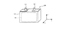
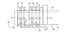
130:電池ケース、140:発電要素、200:仕切り板、210:板本体、
220:突起部、230:第1腕部、240:第2腕部、231,241:傾斜面、
232,242:ピン、233,243:ガイド面、250:第3腕部、
260:第4腕部、251,261:ピン、300:エンドプレート、310:バンド、500:拘束治具、510:第1ストッパ、520:第2ストッパ、
530:ガイド部材、540:アーム
Claims (7)
- 所定方向で隣り合って配置される2つの蓄電素子の間に配置される仕切り板であって、
前記仕切り板に対して前記蓄電素子を配置するときに、前記仕切り板を前記所定方向に移動させるためのガイド部と、
前記所定方向に突出しており、前記所定方向における前記仕切り板の位置決めに用いられる第1ピンと、
前記仕切り板の上下方向において前記第1ピンとは異なる位置に設けられ、前記第1ピンの突出方向と同一方向に突出する第2ピンと、
を有することを特徴とする仕切り板。 - 前記ガイド部および前記第2ピンが、前記所定方向に延びる同一面を形成することを特徴とする請求項1に記載の仕切り板。
- 前記第1ピンおよび前記第2ピンは、前記所定方向における長さが互いに等しいことを特徴とする請求項1又は2に記載の仕切り板。
- 前記第1ピンおよび前記第2ピンの前記所定方向における長さは、前記所定方向における前記蓄電素子の厚さよりも小さいことを特徴とする請求項3に記載の仕切り板。
- 前記第1ピンおよび前記第2ピンのそれぞれを複数有することを特徴とする請求項1から4のいずれか1つに記載の仕切り板。
- 複数の前記第1ピンと、複数の前記第2ピンとによって囲まれる領域内に、前記仕切り板の重心が位置していることを特徴とする請求項5に記載の仕切り板。
- 所定方向に並んで配置された複数の蓄電素子と、前記所定方向で隣り合う2つの前記蓄電素子の間にそれぞれ配置された複数の仕切り板とを有する蓄電装置において、前記蓄電素子を拘束する拘束方法であって、
前記各仕切り板に形成された第1ピンを用いて、前記所定方向で隣り合う2つの前記仕切り板の間隔を規定する工程と、
前記所定方向で隣り合う2つの前記仕切り板の間に、前記蓄電素子を挿入する工程と、
前記蓄電素子に対して前記所定方向の拘束力を与える工程と、を有し、
前記各仕切り板に形成されたガイド部を用いて、前記各仕切り板を前記所定方向に移動させるとき、前記仕切り板の上下方向において前記第1ピンとは異なる位置に設けられ、前記第1ピンの突出方向と同一方向に突出する第2ピンを用いて、前記所定方向に対する前記各仕切り板の傾きを抑制することを特徴とする拘束方法。
Priority Applications (3)
| Application Number | Priority Date | Filing Date | Title |
|---|---|---|---|
| JP2012178203A JP5742800B2 (ja) | 2012-08-10 | 2012-08-10 | 仕切り板および蓄電素子の拘束方法 |
| US13/946,376 US9468115B2 (en) | 2012-08-10 | 2013-07-19 | Partition board, and method of restraining electrical storage elements |
| CN201310344184.9A CN103579566B (zh) | 2012-08-10 | 2013-08-08 | 隔板和约束蓄电元件的方法 |
Applications Claiming Priority (1)
| Application Number | Priority Date | Filing Date | Title |
|---|---|---|---|
| JP2012178203A JP5742800B2 (ja) | 2012-08-10 | 2012-08-10 | 仕切り板および蓄電素子の拘束方法 |
Publications (2)
| Publication Number | Publication Date |
|---|---|
| JP2014035985A true JP2014035985A (ja) | 2014-02-24 |
| JP5742800B2 JP5742800B2 (ja) | 2015-07-01 |
Family
ID=50050888
Family Applications (1)
| Application Number | Title | Priority Date | Filing Date |
|---|---|---|---|
| JP2012178203A Active JP5742800B2 (ja) | 2012-08-10 | 2012-08-10 | 仕切り板および蓄電素子の拘束方法 |
Country Status (3)
| Country | Link |
|---|---|
| US (1) | US9468115B2 (ja) |
| JP (1) | JP5742800B2 (ja) |
| CN (1) | CN103579566B (ja) |
Families Citing this family (3)
| Publication number | Priority date | Publication date | Assignee | Title |
|---|---|---|---|---|
| DE102014221724B4 (de) * | 2014-07-11 | 2025-01-23 | Robert Bosch Gmbh | Vorrichtung zur Anordnung einer Vielzahl von Batteriezellen |
| JP6729342B2 (ja) * | 2016-12-15 | 2020-07-22 | トヨタ自動車株式会社 | 二次電池スタックの製造方法 |
| CN215070102U (zh) | 2021-04-13 | 2021-12-07 | 宁德时代新能源科技股份有限公司 | 中隔板定位装置及电池模组装配设备 |
Citations (2)
| Publication number | Priority date | Publication date | Assignee | Title |
|---|---|---|---|---|
| WO2010131700A1 (ja) * | 2009-05-14 | 2010-11-18 | 株式会社Gsユアサ | 組電池 |
| JP2011023266A (ja) * | 2009-07-17 | 2011-02-03 | Nissan Motor Co Ltd | 組電池およびその製造方法 |
Family Cites Families (3)
| Publication number | Priority date | Publication date | Assignee | Title |
|---|---|---|---|---|
| US4990097A (en) * | 1990-02-21 | 1991-02-05 | Amp Incorporated | Electrical connector with module extraction apparatus |
| CN102273001B (zh) | 2010-03-08 | 2013-11-27 | 丰田自动车株式会社 | 非水电解液二次电池的处理装置和制造方法 |
| JP5535794B2 (ja) * | 2010-06-30 | 2014-07-02 | 三洋電機株式会社 | 組電池 |
-
2012
- 2012-08-10 JP JP2012178203A patent/JP5742800B2/ja active Active
-
2013
- 2013-07-19 US US13/946,376 patent/US9468115B2/en active Active
- 2013-08-08 CN CN201310344184.9A patent/CN103579566B/zh active Active
Patent Citations (2)
| Publication number | Priority date | Publication date | Assignee | Title |
|---|---|---|---|---|
| WO2010131700A1 (ja) * | 2009-05-14 | 2010-11-18 | 株式会社Gsユアサ | 組電池 |
| JP2011023266A (ja) * | 2009-07-17 | 2011-02-03 | Nissan Motor Co Ltd | 組電池およびその製造方法 |
Also Published As
| Publication number | Publication date |
|---|---|
| JP5742800B2 (ja) | 2015-07-01 |
| US9468115B2 (en) | 2016-10-11 |
| US20140041901A1 (en) | 2014-02-13 |
| CN103579566B (zh) | 2016-06-15 |
| CN103579566A (zh) | 2014-02-12 |
Similar Documents
| Publication | Publication Date | Title |
|---|---|---|
| JP7037007B2 (ja) | 拡張型バッテリーモジュール構造を有するバッテリーパック | |
| JP7050849B2 (ja) | バッテリパック | |
| EP2645454B1 (en) | Bus bar assembly having a novel structure | |
| EP3293805B1 (en) | Battery pack assembly press and process of manufacturing a battery pack | |
| US20120129036A1 (en) | Electric storage apparatus | |
| EP3293791A1 (en) | Battery system housing with internal busbar | |
| US20170033339A1 (en) | Electricity storage system | |
| JP2012252811A (ja) | 電源装置、電源装置を備える車両、バスバー | |
| CN104137295B (zh) | 蓄电装置 | |
| US10103414B2 (en) | Battery system assembly process and battery system assembly | |
| KR102906239B1 (ko) | 전지 팩 | |
| KR20190009340A (ko) | 커버 어셈블리를 포함한 배터리 모듈 | |
| CN216120407U (zh) | 软包电池单元和电池模块 | |
| WO2019163381A1 (ja) | 電池モジュール | |
| JP2015088312A (ja) | 電源装置 | |
| JP5742800B2 (ja) | 仕切り板および蓄電素子の拘束方法 | |
| EP3293789A1 (en) | Battery system housing with internal busbar | |
| JP7637317B2 (ja) | バッテリーパック及びこれを含む自動車 | |
| JP2017162711A (ja) | 電池モジュール及び組電池 | |
| CN217009379U (zh) | 电能存储模块 | |
| JP2009272169A (ja) | 蓄電装置 | |
| JP2023114147A (ja) | 電池パック | |
| EP4266469B1 (en) | Battery module, battery pack and vehicle comprising the battery module, and method for manufacturing the battery module | |
| KR102943036B1 (ko) | 배터리 모듈 및 이의 제조 방법 | |
| KR102739751B1 (ko) | 카운터바 홀을 구비한 배터리 셀용 카트리지 및 이를 포함하는 배터리 모듈 조립체 |
Legal Events
| Date | Code | Title | Description |
|---|---|---|---|
| A621 | Written request for application examination |
Free format text: JAPANESE INTERMEDIATE CODE: A621 Effective date: 20140127 |
|
| A977 | Report on retrieval |
Free format text: JAPANESE INTERMEDIATE CODE: A971007 Effective date: 20140610 |
|
| A131 | Notification of reasons for refusal |
Free format text: JAPANESE INTERMEDIATE CODE: A131 Effective date: 20140722 |
|
| A521 | Request for written amendment filed |
Free format text: JAPANESE INTERMEDIATE CODE: A523 Effective date: 20140922 |
|
| TRDD | Decision of grant or rejection written | ||
| A01 | Written decision to grant a patent or to grant a registration (utility model) |
Free format text: JAPANESE INTERMEDIATE CODE: A01 Effective date: 20150407 |
|
| A61 | First payment of annual fees (during grant procedure) |
Free format text: JAPANESE INTERMEDIATE CODE: A61 Effective date: 20150420 |
|
| R151 | Written notification of patent or utility model registration |
Ref document number: 5742800 Country of ref document: JP Free format text: JAPANESE INTERMEDIATE CODE: R151 |