JP2014014384A - Golf ball - Google Patents
Golf ball Download PDFInfo
- Publication number
- JP2014014384A JP2014014384A JP2012136296A JP2012136296A JP2014014384A JP 2014014384 A JP2014014384 A JP 2014014384A JP 2012136296 A JP2012136296 A JP 2012136296A JP 2012136296 A JP2012136296 A JP 2012136296A JP 2014014384 A JP2014014384 A JP 2014014384A
- Authority
- JP
- Japan
- Prior art keywords
- golf ball
- less
- ball according
- polyol
- coating film
- Prior art date
- Legal status (The legal status is an assumption and is not a legal conclusion. Google has not performed a legal analysis and makes no representation as to the accuracy of the status listed.)
- Granted
Links
- 238000000576 coating method Methods 0.000 claims abstract description 89
- 239000011248 coating agent Substances 0.000 claims abstract description 88
- 238000005259 measurement Methods 0.000 claims abstract description 40
- 238000003860 storage Methods 0.000 claims abstract description 28
- 229920005862 polyol Polymers 0.000 claims description 75
- 239000005056 polyisocyanate Substances 0.000 claims description 60
- 229920001228 polyisocyanate Polymers 0.000 claims description 60
- 150000003077 polyols Chemical class 0.000 claims description 59
- -1 urethane polyol Chemical class 0.000 claims description 42
- 229920005989 resin Polymers 0.000 claims description 36
- 239000011347 resin Substances 0.000 claims description 36
- 125000002887 hydroxy group Chemical group [H]O* 0.000 claims description 29
- RRAMGCGOFNQTLD-UHFFFAOYSA-N hexamethylene diisocyanate Chemical class O=C=NCCCCCCN=C=O RRAMGCGOFNQTLD-UHFFFAOYSA-N 0.000 claims description 26
- 229920002635 polyurethane Polymers 0.000 claims description 23
- 239000004814 polyurethane Substances 0.000 claims description 23
- NIMLQBUJDJZYEJ-UHFFFAOYSA-N isophorone diisocyanate Chemical class CC1(C)CC(N=C=O)CC(C)(CN=C=O)C1 NIMLQBUJDJZYEJ-UHFFFAOYSA-N 0.000 claims description 22
- 239000005057 Hexamethylene diisocyanate Substances 0.000 claims description 16
- IQPQWNKOIGAROB-UHFFFAOYSA-N isocyanate group Chemical group [N-]=C=O IQPQWNKOIGAROB-UHFFFAOYSA-N 0.000 claims description 15
- 150000002009 diols Chemical class 0.000 claims description 13
- 239000005058 Isophorone diisocyanate Substances 0.000 claims description 10
- XSTXAVWGXDQKEL-UHFFFAOYSA-N Trichloroethylene Chemical compound ClC=C(Cl)Cl XSTXAVWGXDQKEL-UHFFFAOYSA-N 0.000 claims description 10
- 238000002156 mixing Methods 0.000 claims description 10
- ZFSLODLOARCGLH-UHFFFAOYSA-N isocyanuric acid Chemical compound OC1=NC(O)=NC(O)=N1 ZFSLODLOARCGLH-UHFFFAOYSA-N 0.000 claims description 8
- 238000006243 chemical reaction Methods 0.000 claims description 6
- 230000005284 excitation Effects 0.000 claims description 4
- 238000013459 approach Methods 0.000 abstract description 34
- 239000010410 layer Substances 0.000 description 55
- 239000000203 mixture Substances 0.000 description 55
- 239000000463 material Substances 0.000 description 32
- 229920001971 elastomer Polymers 0.000 description 31
- 239000003973 paint Substances 0.000 description 28
- 229920000554 ionomer Polymers 0.000 description 23
- LYCAIKOWRPUZTN-UHFFFAOYSA-N Ethylene glycol Chemical compound OCCO LYCAIKOWRPUZTN-UHFFFAOYSA-N 0.000 description 21
- 239000003795 chemical substances by application Substances 0.000 description 18
- 239000005060 rubber Substances 0.000 description 17
- FKTHNVSLHLHISI-UHFFFAOYSA-N 1,2-bis(isocyanatomethyl)benzene Chemical compound O=C=NCC1=CC=CC=C1CN=C=O FKTHNVSLHLHISI-UHFFFAOYSA-N 0.000 description 14
- 239000000806 elastomer Substances 0.000 description 14
- 239000011701 zinc Substances 0.000 description 14
- NIXOWILDQLNWCW-UHFFFAOYSA-M Acrylate Chemical compound [O-]C(=O)C=C NIXOWILDQLNWCW-UHFFFAOYSA-M 0.000 description 13
- 229920003182 Surlyn® Polymers 0.000 description 13
- NIXOWILDQLNWCW-UHFFFAOYSA-N acrylic acid group Chemical group C(C=C)(=O)O NIXOWILDQLNWCW-UHFFFAOYSA-N 0.000 description 13
- 238000000034 method Methods 0.000 description 13
- 239000011734 sodium Substances 0.000 description 13
- 239000000178 monomer Substances 0.000 description 12
- 229920002803 thermoplastic polyurethane Polymers 0.000 description 12
- UPMLOUAZCHDJJD-UHFFFAOYSA-N 4,4'-Diphenylmethane Diisocyanate Chemical compound C1=CC(N=C=O)=CC=C1CC1=CC=C(N=C=O)C=C1 UPMLOUAZCHDJJD-UHFFFAOYSA-N 0.000 description 11
- 241000428199 Mustelinae Species 0.000 description 11
- 238000000748 compression moulding Methods 0.000 description 11
- 229920006347 Elastollan Polymers 0.000 description 10
- TZCXTZWJZNENPQ-UHFFFAOYSA-L barium sulfate Chemical compound [Ba+2].[O-]S([O-])(=O)=O TZCXTZWJZNENPQ-UHFFFAOYSA-L 0.000 description 10
- 238000000465 moulding Methods 0.000 description 10
- ZWEHNKRNPOVVGH-UHFFFAOYSA-N 2-Butanone Chemical compound CCC(C)=O ZWEHNKRNPOVVGH-UHFFFAOYSA-N 0.000 description 9
- CERQOIWHTDAKMF-UHFFFAOYSA-N Methacrylic acid Chemical class CC(=C)C(O)=O CERQOIWHTDAKMF-UHFFFAOYSA-N 0.000 description 9
- 239000004433 Thermoplastic polyurethane Substances 0.000 description 9
- YXFVVABEGXRONW-UHFFFAOYSA-N Toluene Chemical compound CC1=CC=CC=C1 YXFVVABEGXRONW-UHFFFAOYSA-N 0.000 description 9
- 229920005648 ethylene methacrylic acid copolymer Polymers 0.000 description 9
- 238000001746 injection moulding Methods 0.000 description 9
- DVKJHBMWWAPEIU-UHFFFAOYSA-N toluene 2,4-diisocyanate Chemical compound CC1=CC=C(N=C=O)C=C1N=C=O DVKJHBMWWAPEIU-UHFFFAOYSA-N 0.000 description 9
- WGCNASOHLSPBMP-UHFFFAOYSA-N hydroxyacetaldehyde Natural products OCC=O WGCNASOHLSPBMP-UHFFFAOYSA-N 0.000 description 8
- 239000011777 magnesium Substances 0.000 description 8
- 229910052751 metal Inorganic materials 0.000 description 8
- 239000002184 metal Substances 0.000 description 8
- 150000003839 salts Chemical class 0.000 description 8
- 239000000126 substance Substances 0.000 description 8
- 239000002344 surface layer Substances 0.000 description 8
- NNOZGCICXAYKLW-UHFFFAOYSA-N 1,2-bis(2-isocyanatopropan-2-yl)benzene Chemical compound O=C=NC(C)(C)C1=CC=CC=C1C(C)(C)N=C=O NNOZGCICXAYKLW-UHFFFAOYSA-N 0.000 description 7
- BYPFICORERPGJY-UHFFFAOYSA-N 3,4-diisocyanatobicyclo[2.2.1]hept-2-ene Chemical compound C1CC2(N=C=O)C(N=C=O)=CC1C2 BYPFICORERPGJY-UHFFFAOYSA-N 0.000 description 7
- 125000005442 diisocyanate group Chemical group 0.000 description 7
- 229910021645 metal ion Inorganic materials 0.000 description 7
- 238000012360 testing method Methods 0.000 description 7
- 150000007934 α,β-unsaturated carboxylic acids Chemical class 0.000 description 7
- ALQLPWJFHRMHIU-UHFFFAOYSA-N 1,4-diisocyanatobenzene Chemical compound O=C=NC1=CC=C(N=C=O)C=C1 ALQLPWJFHRMHIU-UHFFFAOYSA-N 0.000 description 6
- PEDCQBHIVMGVHV-UHFFFAOYSA-N Glycerine Chemical compound OCC(O)CO PEDCQBHIVMGVHV-UHFFFAOYSA-N 0.000 description 6
- 125000003118 aryl group Chemical group 0.000 description 6
- 125000004432 carbon atom Chemical group C* 0.000 description 6
- 150000001732 carboxylic acid derivatives Chemical class 0.000 description 6
- MTHSVFCYNBDYFN-UHFFFAOYSA-N diethylene glycol Chemical compound OCCOCCO MTHSVFCYNBDYFN-UHFFFAOYSA-N 0.000 description 6
- 229920000768 polyamine Polymers 0.000 description 6
- 229920000642 polymer Polymers 0.000 description 6
- 238000001228 spectrum Methods 0.000 description 6
- RUELTTOHQODFPA-UHFFFAOYSA-N toluene 2,6-diisocyanate Chemical compound CC1=C(N=C=O)C=CC=C1N=C=O RUELTTOHQODFPA-UHFFFAOYSA-N 0.000 description 6
- FKNQFGJONOIPTF-UHFFFAOYSA-N Sodium cation Chemical compound [Na+] FKNQFGJONOIPTF-UHFFFAOYSA-N 0.000 description 5
- 229910001415 sodium ion Inorganic materials 0.000 description 5
- 238000005507 spraying Methods 0.000 description 5
- VZCYOOQTPOCHFL-UHFFFAOYSA-N trans-butenedioic acid Natural products OC(=O)C=CC(O)=O VZCYOOQTPOCHFL-UHFFFAOYSA-N 0.000 description 5
- PUPZLCDOIYMWBV-UHFFFAOYSA-N (+/-)-1,3-Butanediol Chemical compound CC(O)CCO PUPZLCDOIYMWBV-UHFFFAOYSA-N 0.000 description 4
- SMZOUWXMTYCWNB-UHFFFAOYSA-N 2-(2-methoxy-5-methylphenyl)ethanamine Chemical compound COC1=CC=C(C)C=C1CCN SMZOUWXMTYCWNB-UHFFFAOYSA-N 0.000 description 4
- VZCYOOQTPOCHFL-OWOJBTEDSA-N Fumaric acid Chemical compound OC(=O)\C=C\C(O)=O VZCYOOQTPOCHFL-OWOJBTEDSA-N 0.000 description 4
- ATUOYWHBWRKTHZ-UHFFFAOYSA-N Propane Chemical compound CCC ATUOYWHBWRKTHZ-UHFFFAOYSA-N 0.000 description 4
- PPBRXRYQALVLMV-UHFFFAOYSA-N Styrene Chemical compound C=CC1=CC=CC=C1 PPBRXRYQALVLMV-UHFFFAOYSA-N 0.000 description 4
- XLOMVQKBTHCTTD-UHFFFAOYSA-N Zinc monoxide Chemical compound [Zn]=O XLOMVQKBTHCTTD-UHFFFAOYSA-N 0.000 description 4
- 125000001931 aliphatic group Chemical group 0.000 description 4
- WERYXYBDKMZEQL-UHFFFAOYSA-N butane-1,4-diol Chemical compound OCCCCO WERYXYBDKMZEQL-UHFFFAOYSA-N 0.000 description 4
- 125000003178 carboxy group Chemical group [H]OC(*)=O 0.000 description 4
- 238000004132 cross linking Methods 0.000 description 4
- 239000003431 cross linking reagent Substances 0.000 description 4
- 239000003999 initiator Substances 0.000 description 4
- 150000002898 organic sulfur compounds Chemical class 0.000 description 4
- 229920001610 polycaprolactone Polymers 0.000 description 4
- 239000004417 polycarbonate Substances 0.000 description 4
- 229920005906 polyester polyol Polymers 0.000 description 4
- 229920000921 polyethylene adipate Polymers 0.000 description 4
- 229920001451 polypropylene glycol Polymers 0.000 description 4
- 239000002904 solvent Substances 0.000 description 4
- 239000007921 spray Substances 0.000 description 4
- 239000012463 white pigment Substances 0.000 description 4
- 229910052725 zinc Inorganic materials 0.000 description 4
- SBJCUZQNHOLYMD-UHFFFAOYSA-N 1,5-Naphthalene diisocyanate Chemical compound C1=CC=C2C(N=C=O)=CC=CC2=C1N=C=O SBJCUZQNHOLYMD-UHFFFAOYSA-N 0.000 description 3
- ICLCCFKUSALICQ-UHFFFAOYSA-N 1-isocyanato-4-(4-isocyanato-3-methylphenyl)-2-methylbenzene Chemical compound C1=C(N=C=O)C(C)=CC(C=2C=C(C)C(N=C=O)=CC=2)=C1 ICLCCFKUSALICQ-UHFFFAOYSA-N 0.000 description 3
- XMNIXWIUMCBBBL-UHFFFAOYSA-N 2-(2-phenylpropan-2-ylperoxy)propan-2-ylbenzene Chemical compound C=1C=CC=CC=1C(C)(C)OOC(C)(C)C1=CC=CC=C1 XMNIXWIUMCBBBL-UHFFFAOYSA-N 0.000 description 3
- GUUVPOWQJOLRAS-UHFFFAOYSA-N Diphenyl disulfide Chemical class C=1C=CC=CC=1SSC1=CC=CC=C1 GUUVPOWQJOLRAS-UHFFFAOYSA-N 0.000 description 3
- VGGSQFUCUMXWEO-UHFFFAOYSA-N Ethene Chemical compound C=C VGGSQFUCUMXWEO-UHFFFAOYSA-N 0.000 description 3
- XEKOWRVHYACXOJ-UHFFFAOYSA-N Ethyl acetate Chemical compound CCOC(C)=O XEKOWRVHYACXOJ-UHFFFAOYSA-N 0.000 description 3
- 239000005977 Ethylene Substances 0.000 description 3
- KFZMGEQAYNKOFK-UHFFFAOYSA-N Isopropanol Chemical compound CC(C)O KFZMGEQAYNKOFK-UHFFFAOYSA-N 0.000 description 3
- OFOBLEOULBTSOW-UHFFFAOYSA-N Propanedioic acid Natural products OC(=O)CC(O)=O OFOBLEOULBTSOW-UHFFFAOYSA-N 0.000 description 3
- ZJCCRDAZUWHFQH-UHFFFAOYSA-N Trimethylolpropane Chemical compound CCC(CO)(CO)CO ZJCCRDAZUWHFQH-UHFFFAOYSA-N 0.000 description 3
- PTFCDOFLOPIGGS-UHFFFAOYSA-N Zinc dication Chemical compound [Zn+2] PTFCDOFLOPIGGS-UHFFFAOYSA-N 0.000 description 3
- 150000001336 alkenes Chemical class 0.000 description 3
- 230000003712 anti-aging effect Effects 0.000 description 3
- 229920001577 copolymer Polymers 0.000 description 3
- 230000007423 decrease Effects 0.000 description 3
- 230000000694 effects Effects 0.000 description 3
- 238000005227 gel permeation chromatography Methods 0.000 description 3
- 235000011187 glycerol Nutrition 0.000 description 3
- VZCYOOQTPOCHFL-UPHRSURJSA-N maleic acid Chemical compound OC(=O)\C=C/C(O)=O VZCYOOQTPOCHFL-UPHRSURJSA-N 0.000 description 3
- 239000011976 maleic acid Substances 0.000 description 3
- 238000004519 manufacturing process Methods 0.000 description 3
- VLKZOEOYAKHREP-UHFFFAOYSA-N n-Hexane Chemical compound CCCCCC VLKZOEOYAKHREP-UHFFFAOYSA-N 0.000 description 3
- JRZJOMJEPLMPRA-UHFFFAOYSA-N olefin Natural products CCCCCCCC=C JRZJOMJEPLMPRA-UHFFFAOYSA-N 0.000 description 3
- 229920006122 polyamide resin Polymers 0.000 description 3
- 238000002360 preparation method Methods 0.000 description 3
- 229910001220 stainless steel Inorganic materials 0.000 description 3
- 239000010935 stainless steel Substances 0.000 description 3
- 230000003746 surface roughness Effects 0.000 description 3
- 229920006027 ternary co-polymer Polymers 0.000 description 3
- 229920001897 terpolymer Polymers 0.000 description 3
- 150000004072 triols Chemical class 0.000 description 3
- XLYOFNOQVPJJNP-UHFFFAOYSA-N water Substances O XLYOFNOQVPJJNP-UHFFFAOYSA-N 0.000 description 3
- HNVRRHSXBLFLIG-UHFFFAOYSA-N 3-hydroxy-3-methylbut-1-ene Chemical compound CC(C)(O)C=C HNVRRHSXBLFLIG-UHFFFAOYSA-N 0.000 description 2
- VTYYLEPIZMXCLO-UHFFFAOYSA-L Calcium carbonate Chemical compound [Ca+2].[O-]C([O-])=O VTYYLEPIZMXCLO-UHFFFAOYSA-L 0.000 description 2
- OKTJSMMVPCPJKN-UHFFFAOYSA-N Carbon Chemical compound [C] OKTJSMMVPCPJKN-UHFFFAOYSA-N 0.000 description 2
- CURLTUGMZLYLDI-UHFFFAOYSA-N Carbon dioxide Chemical compound O=C=O CURLTUGMZLYLDI-UHFFFAOYSA-N 0.000 description 2
- 239000004970 Chain extender Substances 0.000 description 2
- JOYRKODLDBILNP-UHFFFAOYSA-N Ethyl urethane Chemical compound CCOC(N)=O JOYRKODLDBILNP-UHFFFAOYSA-N 0.000 description 2
- YNQLUTRBYVCPMQ-UHFFFAOYSA-N Ethylbenzene Chemical compound CCC1=CC=CC=C1 YNQLUTRBYVCPMQ-UHFFFAOYSA-N 0.000 description 2
- 239000005063 High cis polybutadiene Substances 0.000 description 2
- XEEYBQQBJWHFJM-UHFFFAOYSA-N Iron Chemical compound [Fe] XEEYBQQBJWHFJM-UHFFFAOYSA-N 0.000 description 2
- GLUUGHFHXGJENI-UHFFFAOYSA-N Piperazine Chemical compound C1CNCCN1 GLUUGHFHXGJENI-UHFFFAOYSA-N 0.000 description 2
- 229920003171 Poly (ethylene oxide) Polymers 0.000 description 2
- 229920002614 Polyether block amide Polymers 0.000 description 2
- 239000004721 Polyphenylene oxide Substances 0.000 description 2
- 239000004793 Polystyrene Substances 0.000 description 2
- 229910000831 Steel Inorganic materials 0.000 description 2
- WYURNTSHIVDZCO-UHFFFAOYSA-N Tetrahydrofuran Chemical compound C1CCOC1 WYURNTSHIVDZCO-UHFFFAOYSA-N 0.000 description 2
- GWEVSGVZZGPLCZ-UHFFFAOYSA-N Titan oxide Chemical compound O=[Ti]=O GWEVSGVZZGPLCZ-UHFFFAOYSA-N 0.000 description 2
- HCHKCACWOHOZIP-UHFFFAOYSA-N Zinc Chemical compound [Zn] HCHKCACWOHOZIP-UHFFFAOYSA-N 0.000 description 2
- 125000002723 alicyclic group Chemical group 0.000 description 2
- XXROGKLTLUQVRX-UHFFFAOYSA-N allyl alcohol Chemical compound OCC=C XXROGKLTLUQVRX-UHFFFAOYSA-N 0.000 description 2
- 150000001412 amines Chemical class 0.000 description 2
- XITRBUPOXXBIJN-UHFFFAOYSA-N bis(2,2,6,6-tetramethylpiperidin-4-yl) decanedioate Chemical compound C1C(C)(C)NC(C)(C)CC1OC(=O)CCCCCCCCC(=O)OC1CC(C)(C)NC(C)(C)C1 XITRBUPOXXBIJN-UHFFFAOYSA-N 0.000 description 2
- DKPFZGUDAPQIHT-UHFFFAOYSA-N butyl acetate Chemical compound CCCCOC(C)=O DKPFZGUDAPQIHT-UHFFFAOYSA-N 0.000 description 2
- 238000013329 compounding Methods 0.000 description 2
- 150000001875 compounds Chemical class 0.000 description 2
- 239000002612 dispersion medium Substances 0.000 description 2
- 238000001035 drying Methods 0.000 description 2
- 125000001495 ethyl group Chemical group [H]C([H])([H])C([H])([H])* 0.000 description 2
- 239000001530 fumaric acid Substances 0.000 description 2
- 230000005484 gravity Effects 0.000 description 2
- TZMQHOJDDMFGQX-UHFFFAOYSA-N hexane-1,1,1-triol Chemical compound CCCCCC(O)(O)O TZMQHOJDDMFGQX-UHFFFAOYSA-N 0.000 description 2
- NAQMVNRVTILPCV-UHFFFAOYSA-N hexane-1,6-diamine Chemical compound NCCCCCCN NAQMVNRVTILPCV-UHFFFAOYSA-N 0.000 description 2
- XXMIOPMDWAUFGU-UHFFFAOYSA-N hexane-1,6-diol Chemical compound OCCCCCCO XXMIOPMDWAUFGU-UHFFFAOYSA-N 0.000 description 2
- ZXEKIIBDNHEJCQ-UHFFFAOYSA-N isobutanol Chemical compound CC(C)CO ZXEKIIBDNHEJCQ-UHFFFAOYSA-N 0.000 description 2
- CPJRRXSHAYUTGL-UHFFFAOYSA-N isopentenyl alcohol Chemical compound CC(=C)CCO CPJRRXSHAYUTGL-UHFFFAOYSA-N 0.000 description 2
- 150000002596 lactones Chemical class 0.000 description 2
- 239000004611 light stabiliser Substances 0.000 description 2
- 229910052749 magnesium Inorganic materials 0.000 description 2
- 125000002496 methyl group Chemical group [H]C([H])([H])* 0.000 description 2
- ZGEGCLOFRBLKSE-UHFFFAOYSA-N methylene hexane Natural products CCCCCC=C ZGEGCLOFRBLKSE-UHFFFAOYSA-N 0.000 description 2
- 239000012046 mixed solvent Substances 0.000 description 2
- SLCVBVWXLSEKPL-UHFFFAOYSA-N neopentyl glycol Chemical compound OCC(C)(C)CO SLCVBVWXLSEKPL-UHFFFAOYSA-N 0.000 description 2
- 230000003472 neutralizing effect Effects 0.000 description 2
- 150000001451 organic peroxides Chemical class 0.000 description 2
- 239000003960 organic solvent Substances 0.000 description 2
- 230000000704 physical effect Effects 0.000 description 2
- 239000000049 pigment Substances 0.000 description 2
- 229920000515 polycarbonate Polymers 0.000 description 2
- 229920000728 polyester Polymers 0.000 description 2
- 229920000570 polyether Polymers 0.000 description 2
- 229920002223 polystyrene Polymers 0.000 description 2
- ASUAYTHWZCLXAN-UHFFFAOYSA-N prenol Chemical compound CC(C)=CCO ASUAYTHWZCLXAN-UHFFFAOYSA-N 0.000 description 2
- 239000001294 propane Substances 0.000 description 2
- 125000001436 propyl group Chemical group [H]C([*])([H])C([H])([H])C([H])([H])[H] 0.000 description 2
- 239000004576 sand Substances 0.000 description 2
- 238000010008 shearing Methods 0.000 description 2
- 239000002356 single layer Substances 0.000 description 2
- 229910052708 sodium Inorganic materials 0.000 description 2
- 239000003381 stabilizer Substances 0.000 description 2
- 239000010959 steel Substances 0.000 description 2
- 230000001629 suppression Effects 0.000 description 2
- OGIDPMRJRNCKJF-UHFFFAOYSA-N titanium oxide Inorganic materials [Ti]=O OGIDPMRJRNCKJF-UHFFFAOYSA-N 0.000 description 2
- ZIBGPFATKBEMQZ-UHFFFAOYSA-N triethylene glycol Chemical compound OCCOCCOCCO ZIBGPFATKBEMQZ-UHFFFAOYSA-N 0.000 description 2
- 239000006097 ultraviolet radiation absorber Substances 0.000 description 2
- 239000011787 zinc oxide Substances 0.000 description 2
- XKMZOFXGLBYJLS-UHFFFAOYSA-L zinc;prop-2-enoate Chemical compound [Zn+2].[O-]C(=O)C=C.[O-]C(=O)C=C XKMZOFXGLBYJLS-UHFFFAOYSA-L 0.000 description 2
- NEJDKFPXHQRVMV-UHFFFAOYSA-N (E)-2-Methyl-2-buten-1-ol Natural products CC=C(C)CO NEJDKFPXHQRVMV-UHFFFAOYSA-N 0.000 description 1
- NALFRYPTRXKZPN-UHFFFAOYSA-N 1,1-bis(tert-butylperoxy)-3,3,5-trimethylcyclohexane Chemical compound CC1CC(C)(C)CC(OOC(C)(C)C)(OOC(C)(C)C)C1 NALFRYPTRXKZPN-UHFFFAOYSA-N 0.000 description 1
- LGXISKQYIKXYTC-UHFFFAOYSA-N 1,2,3,4,5-pentabromo-6-[(2,3,4,5,6-pentabromophenyl)disulfanyl]benzene Chemical compound BrC1=C(Br)C(Br)=C(Br)C(Br)=C1SSC1=C(Br)C(Br)=C(Br)C(Br)=C1Br LGXISKQYIKXYTC-UHFFFAOYSA-N 0.000 description 1
- GEYOCULIXLDCMW-UHFFFAOYSA-N 1,2-phenylenediamine Chemical compound NC1=CC=CC=C1N GEYOCULIXLDCMW-UHFFFAOYSA-N 0.000 description 1
- LIKMAJRDDDTEIG-UHFFFAOYSA-N 1-hexene Chemical compound CCCCC=C LIKMAJRDDDTEIG-UHFFFAOYSA-N 0.000 description 1
- ARXJGSRGQADJSQ-UHFFFAOYSA-N 1-methoxypropan-2-ol Chemical compound COCC(C)O ARXJGSRGQADJSQ-UHFFFAOYSA-N 0.000 description 1
- KWKAKUADMBZCLK-UHFFFAOYSA-N 1-octene Chemical compound CCCCCCC=C KWKAKUADMBZCLK-UHFFFAOYSA-N 0.000 description 1
- XVSJTVAPLGSCSK-UHFFFAOYSA-N 2,3,6-trimethylbenzenethiol Chemical compound CC1=CC=C(C)C(S)=C1C XVSJTVAPLGSCSK-UHFFFAOYSA-N 0.000 description 1
- VOZKAJLKRJDJLL-UHFFFAOYSA-N 2,4-diaminotoluene Chemical compound CC1=CC=C(N)C=C1N VOZKAJLKRJDJLL-UHFFFAOYSA-N 0.000 description 1
- PISLZQACAJMAIO-UHFFFAOYSA-N 2,4-diethyl-6-methylbenzene-1,3-diamine Chemical compound CCC1=CC(C)=C(N)C(CC)=C1N PISLZQACAJMAIO-UHFFFAOYSA-N 0.000 description 1
- TUIWMHDSXJWXOH-UHFFFAOYSA-N 2,5-dimethylhexan-3-one Chemical compound CC(C)CC(=O)C(C)C TUIWMHDSXJWXOH-UHFFFAOYSA-N 0.000 description 1
- JAHNSTQSQJOJLO-UHFFFAOYSA-N 2-(3-fluorophenyl)-1h-imidazole Chemical compound FC1=CC=CC(C=2NC=CN=2)=C1 JAHNSTQSQJOJLO-UHFFFAOYSA-N 0.000 description 1
- XNWFRZJHXBZDAG-UHFFFAOYSA-N 2-METHOXYETHANOL Chemical compound COCCO XNWFRZJHXBZDAG-UHFFFAOYSA-N 0.000 description 1
- NEJDKFPXHQRVMV-HWKANZROSA-N 2-Methyl-2-buten-1-ol Chemical compound C\C=C(/C)CO NEJDKFPXHQRVMV-HWKANZROSA-N 0.000 description 1
- BZAZNULYLRVMSW-UHFFFAOYSA-N 2-Methyl-2-buten-3-ol Natural products CC(C)=C(C)O BZAZNULYLRVMSW-UHFFFAOYSA-N 0.000 description 1
- NVGOATMUHKIQQG-UHFFFAOYSA-N 2-Methyl-3-buten-1-ol Chemical compound OCC(C)C=C NVGOATMUHKIQQG-UHFFFAOYSA-N 0.000 description 1
- RFCQDOVPMUSZMN-UHFFFAOYSA-N 2-Naphthalenethiol Chemical compound C1=CC=CC2=CC(S)=CC=C21 RFCQDOVPMUSZMN-UHFFFAOYSA-N 0.000 description 1
- 125000000954 2-hydroxyethyl group Chemical group [H]C([*])([H])C([H])([H])O[H] 0.000 description 1
- RNLHGQLZWXBQNY-UHFFFAOYSA-N 3-(aminomethyl)-3,5,5-trimethylcyclohexan-1-amine Chemical compound CC1(C)CC(N)CC(C)(CN)C1 RNLHGQLZWXBQNY-UHFFFAOYSA-N 0.000 description 1
- NSPPRYXGGYQMPY-UHFFFAOYSA-N 3-Methylbuten-2-ol-1 Natural products CC(C)C(O)=C NSPPRYXGGYQMPY-UHFFFAOYSA-N 0.000 description 1
- CNGYZEMWVAWWOB-VAWYXSNFSA-N 5-[[4-anilino-6-[bis(2-hydroxyethyl)amino]-1,3,5-triazin-2-yl]amino]-2-[(e)-2-[4-[[4-anilino-6-[bis(2-hydroxyethyl)amino]-1,3,5-triazin-2-yl]amino]-2-sulfophenyl]ethenyl]benzenesulfonic acid Chemical compound N=1C(NC=2C=C(C(\C=C\C=3C(=CC(NC=4N=C(N=C(NC=5C=CC=CC=5)N=4)N(CCO)CCO)=CC=3)S(O)(=O)=O)=CC=2)S(O)(=O)=O)=NC(N(CCO)CCO)=NC=1NC1=CC=CC=C1 CNGYZEMWVAWWOB-VAWYXSNFSA-N 0.000 description 1
- 229920000178 Acrylic resin Polymers 0.000 description 1
- 239000004925 Acrylic resin Substances 0.000 description 1
- NLHHRLWOUZZQLW-UHFFFAOYSA-N Acrylonitrile Chemical compound C=CC#N NLHHRLWOUZZQLW-UHFFFAOYSA-N 0.000 description 1
- OYPRJOBELJOOCE-UHFFFAOYSA-N Calcium Chemical compound [Ca] OYPRJOBELJOOCE-UHFFFAOYSA-N 0.000 description 1
- 108091006146 Channels Proteins 0.000 description 1
- 229920003307 DuPont™ Surlyn® 8150 Polymers 0.000 description 1
- 229920003304 DuPont™ Surlyn® 8320 Polymers 0.000 description 1
- PIICEJLVQHRZGT-UHFFFAOYSA-N Ethylenediamine Chemical compound NCCN PIICEJLVQHRZGT-UHFFFAOYSA-N 0.000 description 1
- 235000008694 Humulus lupulus Nutrition 0.000 description 1
- UFHFLCQGNIYNRP-UHFFFAOYSA-N Hydrogen Chemical compound [H][H] UFHFLCQGNIYNRP-UHFFFAOYSA-N 0.000 description 1
- DGAQECJNVWCQMB-PUAWFVPOSA-M Ilexoside XXIX Chemical compound C[C@@H]1CC[C@@]2(CC[C@@]3(C(=CC[C@H]4[C@]3(CC[C@@H]5[C@@]4(CC[C@@H](C5(C)C)OS(=O)(=O)[O-])C)C)[C@@H]2[C@]1(C)O)C)C(=O)O[C@H]6[C@@H]([C@H]([C@@H]([C@H](O6)CO)O)O)O.[Na+] DGAQECJNVWCQMB-PUAWFVPOSA-M 0.000 description 1
- FYYHWMGAXLPEAU-UHFFFAOYSA-N Magnesium Chemical compound [Mg] FYYHWMGAXLPEAU-UHFFFAOYSA-N 0.000 description 1
- CTQNGGLPUBDAKN-UHFFFAOYSA-N O-Xylene Chemical compound CC1=CC=CC=C1C CTQNGGLPUBDAKN-UHFFFAOYSA-N 0.000 description 1
- 239000005062 Polybutadiene Substances 0.000 description 1
- 239000004698 Polyethylene Substances 0.000 description 1
- 108010013381 Porins Proteins 0.000 description 1
- 229910004298 SiO 2 Inorganic materials 0.000 description 1
- 235000021355 Stearic acid Nutrition 0.000 description 1
- 229920005655 Surlyn® 6320 Polymers 0.000 description 1
- 229920005656 Surlyn® 8120 Polymers 0.000 description 1
- 229920005657 Surlyn® 9320 Polymers 0.000 description 1
- RTAQQCXQSZGOHL-UHFFFAOYSA-N Titanium Chemical compound [Ti] RTAQQCXQSZGOHL-UHFFFAOYSA-N 0.000 description 1
- GKXVJHDEWHKBFH-UHFFFAOYSA-N [2-(aminomethyl)phenyl]methanamine Chemical compound NCC1=CC=CC=C1CN GKXVJHDEWHKBFH-UHFFFAOYSA-N 0.000 description 1
- 230000021736 acetylation Effects 0.000 description 1
- 238000006640 acetylation reaction Methods 0.000 description 1
- 125000005396 acrylic acid ester group Chemical group 0.000 description 1
- 239000000654 additive Substances 0.000 description 1
- 230000000996 additive effect Effects 0.000 description 1
- 150000001298 alcohols Chemical class 0.000 description 1
- XYLMUPLGERFSHI-UHFFFAOYSA-N alpha-Methylstyrene Chemical compound CC(=C)C1=CC=CC=C1 XYLMUPLGERFSHI-UHFFFAOYSA-N 0.000 description 1
- 229910052782 aluminium Inorganic materials 0.000 description 1
- XAGFODPZIPBFFR-UHFFFAOYSA-N aluminium Chemical compound [Al] XAGFODPZIPBFFR-UHFFFAOYSA-N 0.000 description 1
- 125000003277 amino group Chemical group 0.000 description 1
- 238000004458 analytical method Methods 0.000 description 1
- 239000003963 antioxidant agent Substances 0.000 description 1
- 230000003078 antioxidant effect Effects 0.000 description 1
- 230000015572 biosynthetic process Effects 0.000 description 1
- 230000000903 blocking effect Effects 0.000 description 1
- 238000007664 blowing Methods 0.000 description 1
- 239000001055 blue pigment Substances 0.000 description 1
- 125000000484 butyl group Chemical group [H]C([*])([H])C([H])([H])C([H])([H])C([H])([H])[H] 0.000 description 1
- 229910052791 calcium Inorganic materials 0.000 description 1
- 239000011575 calcium Substances 0.000 description 1
- 229910000019 calcium carbonate Inorganic materials 0.000 description 1
- 238000004364 calculation method Methods 0.000 description 1
- 239000003990 capacitor Substances 0.000 description 1
- 239000001569 carbon dioxide Substances 0.000 description 1
- 229910002092 carbon dioxide Inorganic materials 0.000 description 1
- 150000001733 carboxylic acid esters Chemical class 0.000 description 1
- 150000001735 carboxylic acids Chemical class 0.000 description 1
- 239000002131 composite material Substances 0.000 description 1
- 238000009833 condensation Methods 0.000 description 1
- 230000005494 condensation Effects 0.000 description 1
- 238000001816 cooling Methods 0.000 description 1
- 238000007334 copolymerization reaction Methods 0.000 description 1
- LDHQCZJRKDOVOX-NSCUHMNNSA-N crotonic acid Chemical compound C\C=C\C(O)=O LDHQCZJRKDOVOX-NSCUHMNNSA-N 0.000 description 1
- 238000013481 data capture Methods 0.000 description 1
- 238000013461 design Methods 0.000 description 1
- LSXWFXONGKSEMY-UHFFFAOYSA-N di-tert-butyl peroxide Chemical compound CC(C)(C)OOC(C)(C)C LSXWFXONGKSEMY-UHFFFAOYSA-N 0.000 description 1
- 238000010586 diagram Methods 0.000 description 1
- 150000004985 diamines Chemical class 0.000 description 1
- ZZTCPWRAHWXWCH-UHFFFAOYSA-N diphenylmethanediamine Chemical compound C=1C=CC=CC=1C(N)(N)C1=CC=CC=C1 ZZTCPWRAHWXWCH-UHFFFAOYSA-N 0.000 description 1
- 239000002270 dispersing agent Substances 0.000 description 1
- 238000009503 electrostatic coating Methods 0.000 description 1
- 239000003480 eluent Substances 0.000 description 1
- 229920006351 engineering plastic Polymers 0.000 description 1
- 238000011156 evaluation Methods 0.000 description 1
- 238000001125 extrusion Methods 0.000 description 1
- 239000000945 filler Substances 0.000 description 1
- 239000006081 fluorescent whitening agent Substances 0.000 description 1
- 238000009963 fulling Methods 0.000 description 1
- 239000007789 gas Substances 0.000 description 1
- 238000010438 heat treatment Methods 0.000 description 1
- 125000004051 hexyl group Chemical group [H]C([H])([H])C([H])([H])C([H])([H])C([H])([H])C([H])([H])C([H])([H])* 0.000 description 1
- 238000007731 hot pressing Methods 0.000 description 1
- 229910052739 hydrogen Inorganic materials 0.000 description 1
- 239000001257 hydrogen Substances 0.000 description 1
- 230000001771 impaired effect Effects 0.000 description 1
- 238000010348 incorporation Methods 0.000 description 1
- 238000007373 indentation Methods 0.000 description 1
- 238000002347 injection Methods 0.000 description 1
- 239000007924 injection Substances 0.000 description 1
- 229910052742 iron Inorganic materials 0.000 description 1
- 229940035429 isobutyl alcohol Drugs 0.000 description 1
- 125000000959 isobutyl group Chemical group [H]C([H])([H])C([H])(C([H])([H])[H])C([H])([H])* 0.000 description 1
- 125000001449 isopropyl group Chemical group [H]C([H])([H])C([H])(*)C([H])([H])[H] 0.000 description 1
- 238000004898 kneading Methods 0.000 description 1
- 229910052744 lithium Inorganic materials 0.000 description 1
- 239000002075 main ingredient Substances 0.000 description 1
- 230000014759 maintenance of location Effects 0.000 description 1
- 238000000691 measurement method Methods 0.000 description 1
- 239000002923 metal particle Substances 0.000 description 1
- 125000005641 methacryl group Chemical group 0.000 description 1
- 125000005397 methacrylic acid ester group Chemical group 0.000 description 1
- LVHBHZANLOWSRM-UHFFFAOYSA-N methylenebutanedioic acid Natural products OC(=O)CC(=C)C(O)=O LVHBHZANLOWSRM-UHFFFAOYSA-N 0.000 description 1
- 238000003801 milling Methods 0.000 description 1
- 238000012986 modification Methods 0.000 description 1
- 230000004048 modification Effects 0.000 description 1
- 125000004108 n-butyl group Chemical group [H]C([H])([H])C([H])([H])C([H])([H])C([H])([H])* 0.000 description 1
- QIQXTHQIDYTFRH-UHFFFAOYSA-N octadecanoic acid Chemical compound CCCCCCCCCCCCCCCCCC(O)=O QIQXTHQIDYTFRH-UHFFFAOYSA-N 0.000 description 1
- OQCDKBAXFALNLD-UHFFFAOYSA-N octadecanoic acid Natural products CCCCCCCC(C)CCCCCCCCC(O)=O OQCDKBAXFALNLD-UHFFFAOYSA-N 0.000 description 1
- YWAKXRMUMFPDSH-UHFFFAOYSA-N pentene Chemical compound CCCC=C YWAKXRMUMFPDSH-UHFFFAOYSA-N 0.000 description 1
- 125000001147 pentyl group Chemical group C(CCCC)* 0.000 description 1
- 229920003023 plastic Polymers 0.000 description 1
- 239000004033 plastic Substances 0.000 description 1
- 229920000058 polyacrylate Polymers 0.000 description 1
- 229920001515 polyalkylene glycol Polymers 0.000 description 1
- 229920002647 polyamide Polymers 0.000 description 1
- 229920002857 polybutadiene Polymers 0.000 description 1
- 229920001225 polyester resin Polymers 0.000 description 1
- 239000004645 polyester resin Substances 0.000 description 1
- 229920000573 polyethylene Polymers 0.000 description 1
- 229920006124 polyolefin elastomer Polymers 0.000 description 1
- 229920003225 polyurethane elastomer Polymers 0.000 description 1
- 229920005749 polyurethane resin Polymers 0.000 description 1
- 102000007739 porin activity proteins Human genes 0.000 description 1
- 239000000843 powder Substances 0.000 description 1
- 230000001737 promoting effect Effects 0.000 description 1
- AOHJOMMDDJHIJH-UHFFFAOYSA-N propylenediamine Chemical compound CC(N)CN AOHJOMMDDJHIJH-UHFFFAOYSA-N 0.000 description 1
- KIDHWZJUCRJVML-UHFFFAOYSA-N putrescine Chemical compound NCCCCN KIDHWZJUCRJVML-UHFFFAOYSA-N 0.000 description 1
- IPEHBUMCGVEMRF-UHFFFAOYSA-N pyrazinecarboxamide Chemical compound NC(=O)C1=CN=CC=N1 IPEHBUMCGVEMRF-UHFFFAOYSA-N 0.000 description 1
- 239000002994 raw material Substances 0.000 description 1
- 239000001054 red pigment Substances 0.000 description 1
- 230000002787 reinforcement Effects 0.000 description 1
- 230000000630 rising effect Effects 0.000 description 1
- 238000005488 sandblasting Methods 0.000 description 1
- 229920006395 saturated elastomer Polymers 0.000 description 1
- 238000010112 shell-mould casting Methods 0.000 description 1
- 239000012748 slip agent Substances 0.000 description 1
- 238000009987 spinning Methods 0.000 description 1
- 230000003068 static effect Effects 0.000 description 1
- 239000008117 stearic acid Substances 0.000 description 1
- 239000000758 substrate Substances 0.000 description 1
- 238000004381 surface treatment Methods 0.000 description 1
- 238000009864 tensile test Methods 0.000 description 1
- YLQBMQCUIZJEEH-UHFFFAOYSA-N tetrahydrofuran Natural products C=1C=COC=1 YLQBMQCUIZJEEH-UHFFFAOYSA-N 0.000 description 1
- 229920001169 thermoplastic Polymers 0.000 description 1
- 229920002725 thermoplastic elastomer Polymers 0.000 description 1
- 229920006345 thermoplastic polyamide Polymers 0.000 description 1
- 229920005992 thermoplastic resin Polymers 0.000 description 1
- 239000004416 thermosoftening plastic Substances 0.000 description 1
- 239000010936 titanium Substances 0.000 description 1
- 229910052719 titanium Inorganic materials 0.000 description 1
- LDHQCZJRKDOVOX-UHFFFAOYSA-N trans-crotonic acid Natural products CC=CC(O)=O LDHQCZJRKDOVOX-UHFFFAOYSA-N 0.000 description 1
- 238000009966 trimming Methods 0.000 description 1
- WFKWXMTUELFFGS-UHFFFAOYSA-N tungsten Chemical compound [W] WFKWXMTUELFFGS-UHFFFAOYSA-N 0.000 description 1
- 229910052721 tungsten Inorganic materials 0.000 description 1
- 239000010937 tungsten Substances 0.000 description 1
- AVWRKZWQTYIKIY-UHFFFAOYSA-N urea-1-carboxylic acid Chemical class NC(=O)NC(O)=O AVWRKZWQTYIKIY-UHFFFAOYSA-N 0.000 description 1
- 239000004034 viscosity adjusting agent Substances 0.000 description 1
- 238000005406 washing Methods 0.000 description 1
- 239000008096 xylene Substances 0.000 description 1
- 238000004383 yellowing Methods 0.000 description 1
- XOOUIPVCVHRTMJ-UHFFFAOYSA-L zinc stearate Chemical compound [Zn+2].CCCCCCCCCCCCCCCCCC([O-])=O.CCCCCCCCCCCCCCCCCC([O-])=O XOOUIPVCVHRTMJ-UHFFFAOYSA-L 0.000 description 1
- CHJMFFKHPHCQIJ-UHFFFAOYSA-L zinc;octanoate Chemical compound [Zn+2].CCCCCCCC([O-])=O.CCCCCCCC([O-])=O CHJMFFKHPHCQIJ-UHFFFAOYSA-L 0.000 description 1
Images


Abstract
Description
本発明は、ゴルフボールのスピン性能の改良技術に関するものである。 The present invention relates to a technique for improving the spin performance of a golf ball.
ゴルフボール本体表面には、塗膜が設けられている。塗膜を改良することにより、ゴルフボールの特性を改良することが提案されている。 A coating film is provided on the surface of the golf ball body. It has been proposed to improve the properties of golf balls by improving the coating.
特許文献1には、コアと、このコアの外側に位置するカバーと、このカバーの外側に位置するペイント層を備えており、上記カバーのショアD硬度が61以下であり、上記ペイント層のマルテンス硬度が2.0mgf/μm2以下であるゴルフボールが開示されている。特許文献1のゴルフボールは、スピン性能、スピン速度の安定性及びペイント層の耐久性に優れる。
特許文献2には、ゴルフボール本体とゴルフボール本体表面に設けられた塗膜とを有するゴルフボールであって、前記塗膜は、マルテンス硬度が2.0mgf/μm2以下であり、10%モジュラスに対する50%モジュラスの比(50%モジュラス/10%モジュラス)が1.6以上であることを特徴とするゴルフボールが開示されている。特許文献2のゴルフボールは、ウエット条件、および、ラフ条件でのアプローチショットのスピン量が高い。
特許文献3,4には、ゴルフボールの打出し角を大きくして、止まりやすいゴルフボールが提案されている。特許文献3には、ゴルフボール本体と、ゴルフボール本体表面を被覆するペイント層とを有するゴルフボールであって、前記ペイント層を構成する樹脂成分は、ポリアミド系硬化剤で硬化されたものであり、該ゴルフボールの静止摩擦係数が0.22以下であることを特徴とするゴルフボールが開示されている。特許文献4には、ゴルフボール本体と前記ゴルフボール本体を被覆する塗膜とを有するゴルフボールであって、前記塗膜が金属粒子を含むことを特徴とするゴルフボールが開示されている。
特許文献5には、耐久性、耐ささくれ性が改善されたゴルフボールが提案され、コアとカバー、さらに該カバー上に形成される1層以上のペイントを有し、前記カバーのショアD硬度が50〜65、曲げ弾性率が1000〜2000kgf/cm2であり、前記ペイントの少なくとも最外層の10%モジュラスが5〜50kgf/cm2であることを特徴とする耐久性に優れたゴルフボールが開示されている。
特許文献6には、塗膜の要求特性を犠牲にすることなくスピン保持率を改良したゴルフボールが提案されている。特許文献6には、コアと該コアを被覆する少なくとも1層のカバーと、該カバーの外表面に塗膜を形成したゴルフボールにおいて、前記塗膜厚さが25μm以上125μm以下の範囲で、塗膜の50%モジュラスが5MPa以上50MPa以下の範囲で、最外層カバーの厚さをCL(mm)、前記塗膜の厚さをPL(μm)としたときに次の式(1)で表わされるRが、0.01以上0.5以下の範囲であることを特徴とするゴルフボールが開示されている。
R=PL/CL/1000 …(1)
R = PL / CL / 1000 (1)
ゴルフのスコアメイクには、ドライバーショットの飛距離だけではなく、アプローチショットの精度も重要であることは言うまでもない。しかし、40ヤード未満、特に10ヤード〜20ヤード程度のグリーン周りからのアプローチショットに対するコントロール性については、ほとんど検討されていない。 Needless to say, not only the flight distance of driver shots but also the accuracy of approach shots are important in making scores for golf. However, little consideration has been given to the controllability of approach shots from around the green of less than 40 yards, especially 10 to 20 yards.
本発明は、前記事情に鑑みてなされたものであり、40ヤード未満のアプローチショット、特にグリーン周り(10ヤード〜20ヤード程度)からのアプローチショットに対するコントロール性を高めたゴルフボールを提供することを課題とする。また、本発明は、40ヤード未満のアプローチショットおよび40ヤード〜100ヤード程度の距離のアプローチショットの両方に対するコントロール性が高く、打球感に優れたゴルフボールを提供することも課題とする。さらに、本発明は、40ヤード未満のアプローチショットに対するコントロール性が高く、かつ、ドライバーショットにおけるスピン量を低減できるゴルフボールを提供することを課題とする。 The present invention has been made in view of the above circumstances, and provides a golf ball with improved controllability for approach shots of less than 40 yards, particularly approach shots from around the green (about 10 to 20 yards). Let it be an issue. Another object of the present invention is to provide a golf ball that has high controllability for both approach shots of less than 40 yards and approach shots of a distance of about 40 yards to 100 yards and that has an excellent shot feeling. It is another object of the present invention to provide a golf ball that has high controllability for approach shots of less than 40 yards and that can reduce the spin rate on driver shots.
本発明者らは、40ヤード未満のアプローチショット、特にグリーン周り(10ヤード〜20ヤード程度)からのアプローチショットに対するコントロール性に対して、ゴルフボール本体に設けられる塗膜の機械的物性が影響していることを見出し、本発明を完成した。 The present inventors have affected the mechanical properties of the coating film provided on the golf ball body on the controllability of approach shots less than 40 yards, especially approach shots from around the green (about 10 to 20 yards). As a result, the present invention has been completed.
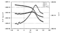
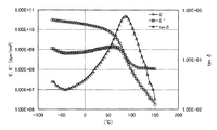
すなわち、本発明のゴルフボールは、コアと前記コアを被覆する少なくとも一層のカバーからなるゴルフボール本体と、前記ゴルフボール本体表面に設けられた塗膜とを有するゴルフボールであって、前記塗膜は、動的粘弾性装置により下記条件にて測定した120℃〜150℃の温度範囲における貯蔵弾性率(E’)の値が、1.00×10⁷dyn/cm2以上、1.00×108dyn/cm2以下、かつ、10℃における損失正接(tanδ)が、0.050以上であり、前記カバーのスラブ硬度が、ショアDで、10以上75以下であることを特徴とする。
<測定条件>
測定モード:引張
測定温度:−50℃〜150℃
昇温速度:4℃/分
加振周波数:10Hz
測定歪み:0.1%
That is, the golf ball of the present invention is a golf ball having a core, a golf ball main body comprising at least one cover covering the core, and a coating film provided on the surface of the golf ball main body. The storage elastic modulus (E ′) in the temperature range of 120 ° C. to 150 ° C. measured by a dynamic viscoelastic device under the following conditions is 1.00 × 10 7 dyn / cm 2 or more, 1.00 × 10 8 dyn / cm 2 or less, loss tangent (tan δ) at 10 ° C. is 0.050 or more, and the slab hardness of the cover is 10 to 75 in Shore D.
<Measurement conditions>
Measurement mode: Tensile Measurement temperature: -50 ° C to 150 ° C
Temperature increase rate: 4 ° C / min Excitation frequency: 10Hz
Measurement distortion: 0.1%
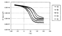
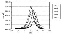
本発明者らは、動的粘弾性装置を用いて、塗膜の貯蔵弾性率(E’)の温度変化を測定したときに、低温領域では、貯蔵弾性率(E’)にほとんど差がない塗膜であっても、120℃〜150℃の高温領域では、貯蔵弾性率に差が生じ、この120℃〜150℃の温度範囲における貯蔵弾性率(E’)が、40ヤード未満のアプローチショットのスピン性能に影響していることを見出した。また、塗膜の損失正接(tanδ)が大きいということは、与えられたエネルギーが熱などのエネルギーに変換されることを意味し、この損失正接(tanδ)が大きいほど40ヤード未満のアプローチショットのスピン性能が向上することを見出した。 When the present inventors measured the temperature change of the storage elastic modulus (E ') of a coating film using a dynamic viscoelastic device, there is almost no difference in storage elastic modulus (E') in a low temperature region. Even if it is a coating film, a difference arises in storage elastic modulus in a high temperature region of 120 ° C. to 150 ° C., and an approach shot in which the storage elastic modulus (E ′) in the temperature range of 120 ° C. to 150 ° C. is less than 40 yards. It has been found that this affects the spin performance. Moreover, the loss tangent (tan δ) of the coating film being large means that the given energy is converted into energy such as heat. The larger the loss tangent (tan δ), the less the approach shot of less than 40 yards. It has been found that spin performance is improved.
前記塗膜は、動的粘弾弾性装置を用いて測定した120℃の貯蔵弾性率(E’120)と、150℃の貯蔵弾性率(E’150)との差の絶対値(│E’120−E’150│)が、2.00×10⁷dyn/cm2以下であることが好ましい。前記塗膜の10%モジュラスは、2kgf/cm2以上、160kgf/cm2以下が好ましく、より好ましくは2kgf/cm2以上、130kgf/cm2以下である。 The coating film has an absolute value (| E ′) of a difference between a storage elastic modulus (E ′ 120 ) measured at 120 ° C. using a dynamic viscoelastic apparatus and a storage elastic modulus (E ′ 150 ) at 150 ° C. 120− E ′ 150 |) is preferably 2.00 × 10 7 dyn / cm 2 or less. 10% modulus of the coating film, 2 kgf / cm 2 or more, preferably 160 kgf / cm 2 or less, more preferably 2 kgf / cm 2 or more and 130 kgf / cm 2 or less.
前記カバーのスラブ硬度は、ショアD硬度で、10以上、55未満であることが好ましい。また、前記カバーのスラブ硬度は、ショアD硬度で、55以上、75以下であることが好ましい。 The slab hardness of the cover is preferably 10 or more and less than 55 in Shore D hardness. Further, the slab hardness of the cover is preferably from 55 to 75 in Shore D hardness.
前記塗膜を構成する基材樹脂は、ポリオールとポリイソシアネートとを反応させてなるポリウレタンであることが好ましく、ポリオールと、2種以上のポリイソシアネートとを反応させてなるポリウレタンがより好ましい。前記ポリオールとポリイソシアネートとの反応において、ポリオールが有する水酸基(OH基)と、ポリイソシアネートが有するイソシアネート基(NCO基)のモル比(NCO/OH)は、0.1以上、1.0以下であることが好ましい。 The base resin constituting the coating film is preferably a polyurethane obtained by reacting a polyol and a polyisocyanate, and more preferably a polyurethane obtained by reacting a polyol and two or more polyisocyanates. In the reaction between the polyol and the polyisocyanate, the molar ratio (NCO / OH) of the hydroxyl group (OH group) of the polyol and the isocyanate group (NCO group) of the polyisocyanate is 0.1 or more and 1.0 or less. Preferably there is.
前記ポリイソシアネートは、ヘキサメチレンジイソシアネートの誘導体と、イソホロンジイソシアネートの誘導体とを含有するものが好ましい。前記ヘキサメチレンジイソシアネートの誘導体と前記イソホロンジイソシアネートの誘導体との混合比率(HDI誘導体/IPDI誘導体)は、質量比で、80/20〜50/50が好ましい。前記ヘキサメチレンジイソシアネートの誘導体は、ヘキサメチレンジイソシアネートのビュレット変性体とイソシアヌレート変性体とを含有することが好ましい。前記イソホロンジイソシアネートの誘導体は、イソホロンジイソシアネートのイソシアヌレート変性体を含有することが好ましい。 The polyisocyanate preferably contains a hexamethylene diisocyanate derivative and an isophorone diisocyanate derivative. The mixing ratio of the hexamethylene diisocyanate derivative and the isophorone diisocyanate derivative (HDI derivative / IPDI derivative) is preferably 80/20 to 50/50 in terms of mass ratio. The hexamethylene diisocyanate derivative preferably contains a burette modified product and an isocyanurate modified product of hexamethylene diisocyanate. The isophorone diisocyanate derivative preferably contains an isocyanurate-modified product of isophorone diisocyanate.
前記ポリオールは、ポリオールとポリイソシアネートとを反応させて得られるウレタンポリオールを含有するものが好ましい。前記ウレタンポリオールを構成するポリオール成分は、トリオール成分とジオール成分とを含有し、トリオール成分とジオール成分の混合比率(トリオール成分/ジオール成分)が、質量比で、0.2以上、6.0以下であることが好ましい。 The polyol preferably contains a urethane polyol obtained by reacting a polyol with a polyisocyanate. The polyol component constituting the urethane polyol contains a triol component and a diol component, and the mixing ratio of the triol component and the diol component (triol component / diol component) is 0.2 to 6.0 in terms of mass ratio. It is preferable that
前記ゴルフボール本体の構造は、2ピース構造、3ピース構造、4ピース構造、または5ピース以上の構造が好ましい。接触力試験機を用いて算出した前記ゴルフボールの摩擦係数は、0.35以上、0.60以下であることが好ましい。前記塗膜の厚みは、10μm以上、50μm以下が好ましい。 The golf ball body preferably has a two-piece structure, a three-piece structure, a four-piece structure, or a five-piece structure or more. The coefficient of friction of the golf ball calculated using a contact force tester is preferably 0.35 or more and 0.60 or less. The thickness of the coating film is preferably 10 μm or more and 50 μm or less.
本発明によれば、40ヤード未満のアプローチショット、特にグリーン周り(10ヤード〜20ヤード程度)からのアプローチショットにおけるコントロール性が高いゴルフボールが得られる。また、カバーのスラブ硬度を、ショアD硬度で10以上55未満とすれば、40ヤード未満のアプローチショットおよび40ヤード〜100ヤード程度の距離のアプローチショットの両方に対するコントロール性が高く、打球感に優れたゴルフボールが得られる。さらに、カバーのスラブ硬度を、ショアD硬度で55以上75以下とすれば、40ヤード未満のアプローチショットに対するコントロール性が高く、かつ、ドライバーショットにおけるスピン量を低減できるゴルフボールが得られる。 According to the present invention, a golf ball having high controllability in an approach shot of less than 40 yards, particularly an approach shot from around the green (about 10 to 20 yards) can be obtained. If the slab hardness of the cover is 10 or more and less than 55 in Shore D hardness, the controllability for both approach shots less than 40 yards and approach shots with a distance of about 40 yards to 100 yards is high, and the shot feel is excellent. Golf ball is obtained. Furthermore, when the slab hardness of the cover is 55 to 75 in terms of Shore D hardness, a golf ball with high controllability for approach shots of less than 40 yards and a reduced spin rate on driver shots can be obtained.
本発明のゴルフボールは、コアと前記コアを被覆する少なくとも一層のカバーからなるゴルフボール本体と、前記ゴルフボール本体表面に設けられた塗膜とを有するゴルフボールであって、前記塗膜は、動的粘弾性装置により下記条件にて測定した120℃〜150℃の温度範囲における貯蔵弾性率(E’)の値が、1.00×10⁷dyn/cm2以上、1.00×108dyn/cm2以下、かつ、10℃における損失正接(tanδ)が、0.050以上であり、前記カバーのスラブ硬度が、ショアDで、10以上75以下であることを特徴とする。
<測定条件>
測定モード:引張
測定温度:−50℃〜150℃
昇温速度:4℃/分
加振周波数:10Hz
測定歪み:0.1%
The golf ball of the present invention is a golf ball having a core and a golf ball main body comprising at least one cover covering the core, and a coating film provided on the surface of the golf ball main body. The value of the storage elastic modulus (E ′) in the temperature range of 120 ° C. to 150 ° C. measured by a dynamic viscoelastic device under the following conditions is 1.00 × 10 7 dyn / cm 2 or more, 1.00 × 10 8. dyn / cm 2 or less, loss tangent (tan δ) at 10 ° C. is 0.050 or more, and the slab hardness of the cover is 10 to 75 in Shore D.
<Measurement conditions>
Measurement mode: Tensile Measurement temperature: -50 ° C to 150 ° C
Temperature increase rate: 4 ° C / min Excitation frequency: 10Hz
Measurement distortion: 0.1%
動的粘弾性装置を用いて前記条件にて測定した120℃〜150℃の温度範囲における貯蔵弾性率(E’)が、1.00×10⁷dyn/cm2以上、1.00×108dyn/cm2以下である塗膜は、40ヤード未満のアプローチショットのスピン量を高くする。その結果、本発明のゴルフボールは、40ヤード未満のアプローチショットのコントロール性が高くなる。この観点から、120℃〜150℃の温度範囲における貯蔵弾性率(E’)は、1.00×108dyn/cm2以下が好ましく、8.00×107dyn/cm2以下がより好ましい。また、値が低すぎるとタック感が残ってしまうという理由から、120℃〜150℃の温度範囲における貯蔵弾性率(E’)は1.00×107dyn/cm2以上が好ましく、1.50×107dyn/cm2以上がより好ましい。 The storage elastic modulus (E ′) in the temperature range of 120 ° C. to 150 ° C. measured using the dynamic viscoelastic device under the above conditions is 1.00 × 10 7 dyn / cm 2 or more, 1.00 × 10 8. A coating film of dyn / cm 2 or less increases the spin rate of approach shots less than 40 yards. As a result, the golf ball of the present invention has high controllability for approach shots of less than 40 yards. From this viewpoint, the storage elastic modulus (E ′) in the temperature range of 120 ° C. to 150 ° C. is preferably 1.00 × 10 8 dyn / cm 2 or less, and more preferably 8.00 × 10 7 dyn / cm 2 or less. . Moreover, the storage elastic modulus (E ′) in the temperature range of 120 ° C. to 150 ° C. is preferably 1.00 × 10 7 dyn / cm 2 or more because the tackiness remains if the value is too low. 50 × 10 7 dyn / cm 2 or more is more preferable.
本発明のゴルフボールの塗膜は、動的粘弾性を測定したときに、120℃〜150℃の領域で、貯蔵弾性率(E’)がほぼ一定になる平坦領域を有することが好ましい。この観点から、動的粘弾弾性装置を用いて測定した120℃の貯蔵弾性率(E’120)と、150℃の貯蔵弾性率(E’150)との差の絶対値(│E’120−E’150│)は、2.00×10⁷dyn/cm2以下が好ましく、1.00×107dyn/cm2以下がより好ましい。 The coating film of the golf ball of the present invention preferably has a flat region where the storage elastic modulus (E ′) is substantially constant in the region of 120 ° C. to 150 ° C. when dynamic viscoelasticity is measured. In this respect, the storage modulus of 120 ° C. as measured with a dynamic viscoelastic acoustic device 'and (120, storage elastic modulus of 0.99 ° C. (E E)' the absolute value of the difference between the 150) (│E '120 -E ′ 150 |) is preferably 2.00 × 10 7 dyn / cm 2 or less, and more preferably 1.00 × 10 7 dyn / cm 2 or less.
本発明のゴルフボールの塗膜は、10℃における損失正接(tanδ)が、0.050以上である。損失正接(tanδ)が0.050以上である塗膜を用いることにより、40ヤード未満のアプローチショットにおいて、打出角を低く、スピン量を高くすることができる。この観点から、10℃における損失正接(tanδ)は、0.050以上がより好ましく、0.060以上がさらに好ましい。また、10℃における損失正接(tanδ)の上限は、1.0である。 The golf ball coating of the present invention has a loss tangent (tan δ) at 10 ° C. of 0.050 or more. By using a coating film having a loss tangent (tan δ) of 0.050 or more, it is possible to reduce the launch angle and increase the spin rate in approach shots of less than 40 yards. From this viewpoint, the loss tangent (tan δ) at 10 ° C. is more preferably 0.050 or more, and further preferably 0.060 or more. The upper limit of the loss tangent (tan δ) at 10 ° C. is 1.0.
塗膜の動的粘弾性は、塗膜を形成する塗料から測定用のフィルムを作製して測定する。測定用フィルムの作製方法および測定方法については、後述する。 The dynamic viscoelasticity of the coating film is measured by preparing a film for measurement from the coating material forming the coating film. The production method and measurement method of the measurement film will be described later.
本発明のゴルフボールは、ゴルフボール本体とゴルフボール本体表面に設けられた塗膜とを有する。前記塗膜を構成する基材樹脂は、前記動的粘弾性特性を満足するものであれば、特に限定されないが、ポリオールと、ポリイソシアネートとを反応させてなるポリウレタンであることが好ましく、ポリオールと、2種以上のポリイソシアネートとを反応させてなるポリウレタンであることがより好ましい。ポリウレタンは、動的粘弾性特性の設計がしやすく、耐久性や密着性にも優れる。塗膜の貯蔵弾性率(E’)及び損失正接(tanδ)は、例えば、ポリオールとポリイソシアネートの種類、配合比率などを適宜選択することにより設定することができる。また、平坦領域の貯蔵弾性率は、例えば、ポリウレタンの分子量や架橋密度などにより制御することができる。 The golf ball of the present invention has a golf ball body and a coating film provided on the surface of the golf ball body. The base resin constituting the coating film is not particularly limited as long as it satisfies the dynamic viscoelastic properties, but is preferably a polyurethane obtained by reacting a polyol and a polyisocyanate, A polyurethane obtained by reacting two or more polyisocyanates is more preferable. Polyurethane is easy to design dynamic viscoelastic properties and has excellent durability and adhesion. The storage elastic modulus (E ′) and loss tangent (tan δ) of the coating film can be set, for example, by appropriately selecting the type and blending ratio of polyol and polyisocyanate. In addition, the storage elastic modulus of the flat region can be controlled by, for example, the molecular weight or crosslink density of polyurethane.
前記ポリオールとしては、分子量が500未満の低分子量ポリオールや平均分子量が500以上の高分子量ポリオールを挙げることができる。前記低分子量ポリオールとしては、例えば、エチレングリコール、ジエチレングリコール、トリエチレングリコール、1,3−ブタンジオール、1,4−ブタンジオール、ネオペンチルグリコール、1,6−ヘキサンジオールなどのジオール;グリセリン、トリメチロールプロパン、ヘキサントリオールなどのトリオールが挙げられる。前記高分子量のポリオールとしては、ポリオキシエチレングリコール(PEG)、ポリオキシプロピレングリコール(PPG)、ポリオキシテトラメチレングリコール(PTMG)などのポリエーテルポリオール;ポリエチレンアジペート(PEA)、ポリブチレンアジペート(PBA)、ポリヘキサメチレンアジペート(PHMA)などの縮合系ポリエステルポリオール;ポリ−ε−カプロラクトン(PCL)などのラクトン系ポリエステルポリオール;ポリヘキサメチレンカーボネートなどのポリカーボネートポリオール;ウレタンポリオール;および、アクリルポリオールなどが挙げられる。前記ポリオール成分は、単独で、あるいは、2種以上を混合して使用しても良い。 Examples of the polyol include a low molecular weight polyol having a molecular weight of less than 500 and a high molecular weight polyol having an average molecular weight of 500 or more. Examples of the low molecular weight polyol include diols such as ethylene glycol, diethylene glycol, triethylene glycol, 1,3-butanediol, 1,4-butanediol, neopentyl glycol, and 1,6-hexanediol; glycerin and trimethylol. Examples include triols such as propane and hexanetriol. Examples of the high molecular weight polyol include polyether polyols such as polyoxyethylene glycol (PEG), polyoxypropylene glycol (PPG), and polyoxytetramethylene glycol (PTMG); polyethylene adipate (PEA), polybutylene adipate (PBA) , Condensation polyester polyols such as polyhexamethylene adipate (PHMA); lactone polyester polyols such as poly-ε-caprolactone (PCL); polycarbonate polyols such as polyhexamethylene carbonate; urethane polyols; and acrylic polyols. . The polyol component may be used alone or in admixture of two or more.
本発明では、ポリオール成分として、ウレタンポリオールを使用することが好ましい。前記ウレタンポリオールとは、分子内にウレタン結合を複数有し、一分子中に水酸基を2以上有する化合物である。ウレタンポリオールとしては、例えば、ポリオールとポリイソシアネートとを、ポリオールの水酸基がポリイソシアネートのイソシアネート基に対して過剰になるような条件で反応させて得られるウレタンプレポリマーを挙げることができる。 In the present invention, it is preferable to use urethane polyol as the polyol component. The urethane polyol is a compound having a plurality of urethane bonds in the molecule and having two or more hydroxyl groups in one molecule. Examples of the urethane polyol include a urethane prepolymer obtained by reacting a polyol and a polyisocyanate under conditions such that the hydroxyl group of the polyol is excessive with respect to the isocyanate group of the polyisocyanate.
前記ウレタンポリオールを構成し得るポリイソシアネート成分としては、イソシアネート基を2以上有するものであれば特に限定されず、例えば、2,4−トルエンジイソシアネート、2,6−トルエンジイソシアネート、2,4−トルエンジイソシアネートと2,6−トルエンジイソシアネートの混合物(TDI)、4,4’−ジフェニルメタンジイソシアネート(MDI)、1,5−ナフチレンジイソシアネート(NDI)、3,3’−ビトリレン−4,4’−ジイソシアネート(TODI)、キシリレンジイソシアネート(XDI)、テトラメチルキシリレンジイソシアネート(TMXDI)、パラフェニレンジイソシアネート(PPDI)などの芳香族ポリイソシアネート;4,4’−ジシクロヘキシルメタンジイソシアネート(H12MDI)、水素添加キシリレンジイソシアネート(H6XDI)、ヘキサメチレンジイソシアネート(HDI)、イソホロンジイソシアネート(IPDI)、ノルボルネンジイソシアネート(NBDI)などの脂環式ポリイソシアネートまたは脂肪族ポリイソシアネートが挙げられる。これらのポリイソシアネートは、単独で使用してもよいし、2種以上を併用してもよい。
The polyisocyanate component that can constitute the urethane polyol is not particularly limited as long as it has two or more isocyanate groups. For example, 2,4-toluene diisocyanate, 2,6-toluene diisocyanate, 2,4-toluene diisocyanate And 2,6-toluene diisocyanate (TDI), 4,4′-diphenylmethane diisocyanate (MDI), 1,5-naphthylene diisocyanate (NDI), 3,3′-vitrylene-4,4′-diisocyanate (TODI) ), xylylene diisocyanate (XDI), tetramethylxylylene diisocyanate (TMXDI), aromatic polyisocyanates such as para-phenylene diisocyanate (PPDI); 4,4'-dicyclohexylmethane diisocyanate (H 12 DI), hydrogenated
ウレタンポリオールを構成し得るポリオール成分としては、前記ポリオールとして例示したものを用いることができる。本発明では、ウレタンポリオールを構成するポリオール成分として、トリオール成分とジオール成分とを含有するものが好ましい。前記トリオール成分としては、トリメチロールプロパンが好ましい。前記ジオール成分としては、ポリオキシテトラメチレングリコールが好ましい。前記トリオール成分とジオール成分の混合比率(トリオール成分/ジオール成分)は、質量比で、0.2以上が好ましく、0.5以上がより好ましく、6.0以下が好ましく、5.0以下がより好ましい。 As the polyol component that can constitute the urethane polyol, those exemplified as the polyol can be used. In this invention, what contains a triol component and a diol component as a polyol component which comprises a urethane polyol is preferable. As the triol component, trimethylolpropane is preferable. As the diol component, polyoxytetramethylene glycol is preferable. The mixing ratio of the triol component and the diol component (triol component / diol component) is, by mass ratio, preferably 0.2 or more, more preferably 0.5 or more, preferably 6.0 or less, and more preferably 5.0 or less. preferable.
アクリルポリオールは、分子内に複数のヒドロキシル基を有するアクリル樹脂またはアクリルポリマーであり、例えば、水酸基を有する(メタ)アクリル系単量体と水酸基を有さない(メタ)アクリル系単量体とを共重合して得られる。なお、本発明において(メタ)アクリルとは、アクリルおよび/またはメタクリルを示す。 The acrylic polyol is an acrylic resin or an acrylic polymer having a plurality of hydroxyl groups in the molecule. For example, a (meth) acrylic monomer having a hydroxyl group and a (meth) acrylic monomer having no hydroxyl group are used. Obtained by copolymerization. In the present invention, (meth) acryl indicates acryl and / or methacryl.
前記水酸基を有する(メタ)アクリル系単量体としては、例えば、(メタ)アクリル酸2−ヒドロキシエチル、(メタ)アクリル酸2−ヒドロキシプロピル、(メタ)アクリル酸2−ヒドロキシブチル、アルキレングリコールモノ(メタ)アクリレート、ポリアルキレングリコールモノ(メタ)アクリレートなどの水酸基を有する(メタ)アクリル酸エステルなどが挙げられる。これらの水酸基を有する(メタ)アクリル系単量体は、単独で用いても2種以上を併用してもよい。 Examples of the (meth) acrylic monomer having a hydroxyl group include 2-hydroxyethyl (meth) acrylate, 2-hydroxypropyl (meth) acrylate, 2-hydroxybutyl (meth) acrylate, alkylene glycol mono Examples include (meth) acrylic acid esters having a hydroxyl group such as (meth) acrylate and polyalkylene glycol mono (meth) acrylate. These (meth) acrylic monomers having a hydroxyl group may be used alone or in combination of two or more.
前記水酸基を有さない(メタ)アクリル系単量体としては、例えば、(メタ)アクリル酸などの(メタ)アクリル系不飽和カルボン酸;(メタ)アクリル酸メチル、(メタ)アクリル酸エチル、(メタ)アクリル酸プロピル、(メタ)アクリル酸イソプロピル、(メタ)アクリル酸ブチル、(メタ)アクリル酸イソブチル、(メタ)アクリル酸ペンチル、(メタ)アクリル酸ヘキシル、(メタ)アクリル酸2−エチルヘキシル、(メタ)アクリル酸シクロへキシル、(メタ)アクリル酸オクチル、(メタ)アクリル酸デシルなどの(メタ)アクリル酸エステル;(メタ)アクリロニトリル、(メタ)アクリルアミドなどのその他(メタ)アクリル系単量体;などが挙げられる。これらの水酸基を有さない(メタ)アクリル系単量体は、単独で用いても2種以上を併用してもよい。 Examples of the (meth) acrylic monomer having no hydroxyl group include (meth) acrylic unsaturated carboxylic acid such as (meth) acrylic acid; methyl (meth) acrylate, ethyl (meth) acrylate, Propyl (meth) acrylate, isopropyl (meth) acrylate, butyl (meth) acrylate, isobutyl (meth) acrylate, pentyl (meth) acrylate, hexyl (meth) acrylate, 2-ethylhexyl (meth) acrylate (Meth) acrylic acid esters such as (meth) acrylic acid cyclohexyl, (meth) acrylic acid octyl, (meth) acrylic acid decyl; (meth) acrylonitrile, (meth) acrylic acid And the like. These (meth) acrylic monomers having no hydroxyl group may be used alone or in combination of two or more.
また、アクリルポリオールは、(メタ)アクリル系単量体以外の水酸基を有する他の単量体成分および/または水酸基を有さない他の単量体成分を含有してもよい。前記水酸基を有する他の単量体成分としては、例えば、3−メチル−3−ブテン−1−オール、3−メチル−2−ブテン−1−オール、2−メチル−3−ブテン−2−オール、2−メチル−2−ブテン−1−オール、2−メチル−3−ブテン−1−オール、アリルアルコールなどの不飽和アルコールが挙げられる。前記水酸基を有さない他の単量体成分としては、例えば、スチレン、α−メチルスチレンなどの芳香族ビニル化合物;マレイン酸、イタコン酸などのエチレン性不飽和カルボン酸;などが挙げられる。これらの他の単量体成分は、単独で用いても2種以上を併用してもよい。 The acrylic polyol may contain other monomer components having a hydroxyl group and / or other monomer components having no hydroxyl group other than the (meth) acrylic monomer. Examples of the other monomer component having a hydroxyl group include 3-methyl-3-buten-1-ol, 3-methyl-2-buten-1-ol, and 2-methyl-3-buten-2-ol. , 2-methyl-2-buten-1-ol, 2-methyl-3-buten-1-ol, and unsaturated alcohols such as allyl alcohol. Examples of the other monomer component having no hydroxyl group include aromatic vinyl compounds such as styrene and α-methylstyrene; ethylenically unsaturated carboxylic acids such as maleic acid and itaconic acid; and the like. These other monomer components may be used alone or in combination of two or more.
前記ポリオールの水酸基価は、10mgKOH/g以上が好ましく、より好ましくは15mgKOH/g以上、さらに好ましくは20mgKOH/g以上であり、400mgKOH/g以下が好ましく、好ましくは300mgKOH/g以下、より好ましくは200mgKOH/g以下、さらに好ましくは170mgKOH/g以下であり、特に好ましくは160mgKOH/g以下である。ポリオール成分の水酸基価が上記範囲内であれば、ゴルフボール本体への塗膜の密着性が向上するからである。なお、本発明において、水酸基価は、JIS K 1557−1に準じて、例えば、アセチル化法によって測定することができる。 The hydroxyl value of the polyol is preferably 10 mgKOH / g or more, more preferably 15 mgKOH / g or more, further preferably 20 mgKOH / g or more, preferably 400 mgKOH / g or less, preferably 300 mgKOH / g or less, more preferably 200 mgKOH. / G or less, more preferably 170 mgKOH / g or less, and particularly preferably 160 mgKOH / g or less. This is because when the hydroxyl value of the polyol component is within the above range, the adhesion of the coating film to the golf ball body is improved. In the present invention, the hydroxyl value can be measured, for example, by an acetylation method according to JIS K1557-1.
前記ポリオールの重量平均分子量は、500以上が好ましく、より好ましくは550以上、さらに好ましくは600以上であり、150,000以下が好ましく、より好ましくは140,000以下、さらに好ましくは130,000以下である。ポリオール成分の重量平均分子量が上記範囲内であれば、塗膜の耐水性、耐衝撃性を向上させることができる。なお、ポリオール成分の重量平均分子量は、例えば、ゲルパーミエーションクロマトグラフィ(GPC)により、標準物質としてポリスチレン、溶離液としてテトラヒドロフラン、カラムとして有機溶媒系GPC用カラム(例えば、昭和電工社製「Shodex(登録商標) KFシリーズ」など)を用いて測定すればよい。 The polyol has a weight average molecular weight of preferably 500 or more, more preferably 550 or more, further preferably 600 or more, preferably 150,000 or less, more preferably 140,000 or less, and further preferably 130,000 or less. is there. When the weight average molecular weight of the polyol component is within the above range, the water resistance and impact resistance of the coating film can be improved. The weight-average molecular weight of the polyol component is determined by, for example, gel permeation chromatography (GPC) using polystyrene as a standard substance, tetrahydrofuran as an eluent, and a column for an organic solvent GPC as a column (for example, “Shodex (registered) manufactured by Showa Denko KK Trademark) KF series "etc.).
前記ポリオール成分の具体例としては、例えば、和薬ペイント社製121B、日本ポリウレタン工業社製ニッポラン(登録商標)800、ニッポラン1100、DIC社製バーノック(登録商標)D6−627、バーノックD8−436、バーノックD8−973、バーノック11−408、住化バイエルウレタン社製デモスフェン650MPA、デモスフェン670、デモスフェン1150、デモスフェンA160X、ハリマ化成社製ハリアクロン2000、ハリアクロン8500H,神東塗料社製ポリン(登録商標)#950などを挙げることができる。 Specific examples of the polyol component include, for example, 121B manufactured by Waku Paint Co., Ltd., Nipponporan (registered trademark) 800, Nipponran 1100 manufactured by Nippon Polyurethane Industry Co., Ltd., Bernock (registered trademark) D6-627 manufactured by DIC, Barnock D8-436, Barnock D8-973, Barnock 11-408, Sumika Bayer Urethane Co., Ltd. Demosphen 650MPA, Demosfen 670, Demosphen 1150, Demosphen A160X, Harima Chemicals Hariacron 2000, Hariacron 8500H, Shinto Paint Co., Ltd. Porin (registered trademark) # 950 And so on.
次に、ポリイソシアネートについて説明する。前記ポリイソシアネートとしては、例えば、イソシアネート基を少なくとも2つ有する化合物を挙げることができる。 Next, polyisocyanate will be described. Examples of the polyisocyanate include compounds having at least two isocyanate groups.
前記ポリイソシアネートとしては、例えば、2,4−トルエンジイソシアネート、2,6−トルエンジイソシアネート、2,4−トルエンジイソシアネートと2,6−トルエンジイソシアネートの混合物(TDI)、4,4’−ジフェニルメタンジイソシアネート(MDI)、1,5−ナフチレンジイソシアネート(NDI)、3,3’−ビトリレン−4,4’−ジイソシアネート(TODI)、キシリレンジイソシアネート(XDI)、テトラメチルキシリレンジイソシアネート(TMXDI)、パラフェニレンジイソシアネート(PPDI)などの芳香族ポリイソシアネート;4,4’−ジシクロヘキシルメタンジイソシアネート(H12MDI)、水素添加キシリレンジイソシアネート(H6XDI)、ヘキサメチレンジイソシアネート(HDI)、イソホロンジイソシアネート(IPDI)、ノルボルネンジイソシアネート(NBDI)などの脂環式ポリイソシアネートまたは脂肪族ポリイソシアネート;およびこれらのポリイソシアネートの誘導体が挙げられる。本発明では、前記ポリイソシアネートとして、2種以上のポリイソシアネートを使用することが好ましい。
Examples of the polyisocyanate include 2,4-toluene diisocyanate, 2,6-toluene diisocyanate, a mixture of 2,4-toluene diisocyanate and 2,6-toluene diisocyanate (TDI), and 4,4′-diphenylmethane diisocyanate (MDI). ), 1,5-naphthylene diisocyanate (NDI), 3,3′-vitrylene-4,4′-diisocyanate (TODI), xylylene diisocyanate (XDI), tetramethylxylylene diisocyanate (TMXDI), paraphenylene diisocyanate ( PPDI) aromatic polyisocyanates such as 4,4'-dicyclohexylmethane diisocyanate (H 12 MDI), hydrogenated
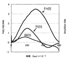
前記ポリイソシアネートの誘導体としては、例えば、ジイソシアネートのイソシアヌレート体;ジイソシアネートとトリメチロールプロパンあるいはグリセリンなどの低分子量トリオールとを反応させて得られるアダクト体;アロハネート変性体;ビュレット変性体などを挙げることができ、遊離ジイソシアネートが除去されているものがより好ましい。前記アロハネート変性体とは、例えば、ジイソシアネートと低分子量ジオールとを反応させて形成されるウレタン結合にさらにジイソシアネートが反応して得られる3官能ポリイソシアネートである。前記ビュレット変性体とは、例えば、下記式(1)で表わされるビュレット結合を有する3官能ポリイソシアネートである。ジイソシアネートのイソシアヌレート体とは、例えば、下記式(2)で表わされる3官能ポリイソシアネートである。なお、式(1)、(2)中、Rは、ジイソシアネートからイソシアネート基を除いた残基を表わす。 Examples of the polyisocyanate derivatives include isocyanurates of diisocyanates; adducts obtained by reacting diisocyanates with low molecular weight triols such as trimethylolpropane or glycerin; modified allophanates; modified burettes, and the like. More preferably, the free diisocyanate is removed. The modified allophanate is, for example, a trifunctional polyisocyanate obtained by further reacting a diisocyanate with a urethane bond formed by reacting a diisocyanate and a low molecular weight diol. The modified burette is, for example, a trifunctional polyisocyanate having a burette bond represented by the following formula (1). The isocyanurate form of diisocyanate is, for example, a trifunctional polyisocyanate represented by the following formula (2). In formulas (1) and (2), R represents a residue obtained by removing an isocyanate group from diisocyanate.
本発明では、ポリイソシアネートとして、ヘキサメチレンジイソシアネートの誘導体と、イソホロンジイソシアネートの誘導体とを使用することが好ましい。ヘキサメチレンジイソシアネートの誘導体として、ヘキサメチレンジイソシアネートのビュレット変性体とイソシアヌレート変性体とを使用することが好ましい。イソホロンジイソシアネートの誘導体としては、イソホロンジイソシアネートのイソシアヌレート変性体を使用することが好ましい。 In the present invention, it is preferable to use a hexamethylene diisocyanate derivative and an isophorone diisocyanate derivative as the polyisocyanate. As the derivative of hexamethylene diisocyanate, it is preferable to use a burette modified product and an isocyanurate modified product of hexamethylene diisocyanate. As a derivative of isophorone diisocyanate, it is preferable to use an isocyanurate-modified product of isophorone diisocyanate.
ヘキサメチレンジイソシアネートの誘導体と、イソホロンジイソシアネートの誘導体との混合比率(HDI誘導体/IPDI誘導体)は、質量比で、80/20〜50/50が好ましく、65/35〜55/45がより好ましい。ヘキサメチレンジイソシアネートのビュレット変性体とイソシアヌレート変性体との混合比率(ビュレット変性体/イソシアヌレート変性体)は、質量比で、20/40〜40/20が好ましく、25/35〜35/25がより好ましい。 The mixing ratio of the derivative of hexamethylene diisocyanate and the derivative of isophorone diisocyanate (HDI derivative / IPDI derivative) is preferably 80/20 to 50/50, more preferably 65/35 to 55/45, in terms of mass ratio. The mixing ratio of the burette modified product and isocyanurate modified product of hexamethylene diisocyanate (burette modified product / isocyanurate modified product) is preferably 20/40 to 40/20, more preferably 25/35 to 35/25, in mass ratio. More preferred.
前記ポリイソシアネートのイソシアネート基量(NCO%)は、0.5質量%以上が好ましく、1質量%以上がより好ましく、2質量%以上がさらに好ましく、45質量%以下が好ましく、40質量%以下がより好ましく、35質量%以下がさらに好ましい。なお、ポリイソシアネートのイソシアネート基量(NCO%)は、100×[ポリイソシアネート中のイソシアネート基のモル数×42(NCOの分子量)]/ポリイソシアネートの総質量(g)で表わすことができる。 The isocyanate group amount (NCO%) of the polyisocyanate is preferably 0.5% by mass or more, more preferably 1% by mass or more, further preferably 2% by mass or more, preferably 45% by mass or less, and preferably 40% by mass or less. More preferred is 35% by mass or less. In addition, the isocyanate group amount (NCO%) of the polyisocyanate can be expressed by 100 × [number of moles of isocyanate groups in the polyisocyanate × 42 (molecular weight of NCO)] / total mass of polyisocyanate (g).
前記ポリイソシアネートの具体例としては、DIC社製バーノック(登録商標)D−800、バーノックDN−950、バーノックDN−955、住化バイエルウレタン社製デスモジュール(登録商標)N75MPA/X、デスモジュールN3300、デスモジュールL75(C)、スミジュールE21−1、日本ポリウレタン工業社製コロネート(登録商標)HX、コロネートHK、旭化成ケミカルズ社製デュラネート(登録商標)24A−100、デュラネート21S−75E、デュラネートTPA−100、デュラネートTKA−100、デグサ社製VESTANAT(登録商標) T1890などを挙げることができる。 Specific examples of the polyisocyanate include DIC's Barnock (registered trademark) D-800, Barnock DN-950, Barnock DN-955, Sumika Bayer Urethane's Death Module (registered trademark) N75MPA / X, Death Module N3300. , Death module L75 (C), Sumidur E21-1, Coronate (registered trademark) HX, Coronate HK manufactured by Nippon Polyurethane Industry Co., Ltd., Duranate (registered trademark) 24A-100, Duranate 21S-75E, Duranate TPA- 100, Duranate TKA-100, Degussa VESTANAT (registered trademark) T1890, and the like.
ポリオールとポリイソシアネートとの反応において、ポリオールが有する水酸基(OH基)とポリイソシアネートが有するイソシアネート基(NCO基)のモル比(NCO基/OH基)は、0.1以上が好ましく、0.2以上がより好ましい。前記モル比(NCO基/OH基)が、0.1未満では、硬化反応が不十分となる。また、前記モル比(NCO基/OH基)が大きくなりすぎると、イソシアネート基量が過剰となり、得られる塗膜が硬く脆くなる上に、外観も悪くなる。そのため、前記モル比(NCO基/OH基)は、1.0以下が好ましく、0.9以下がより好ましく、0.8以下がさらに好ましい。なお、塗料中のイソシアネート基量が過剰になると得られる塗膜の外観が悪くなる理由は、イソシアネート基量が過剰になると、空気中の水分とイソシアネート基との反応が多くなり、炭酸ガスが多量に発生するためと考えられる。 In the reaction between the polyol and the polyisocyanate, the molar ratio (NCO group / OH group) of the hydroxyl group (OH group) of the polyol to the isocyanate group (NCO group) of the polyisocyanate is preferably 0.1 or more, 0.2 The above is more preferable. When the molar ratio (NCO group / OH group) is less than 0.1, the curing reaction is insufficient. On the other hand, if the molar ratio (NCO group / OH group) becomes too large, the amount of isocyanate groups becomes excessive, the resulting coating film becomes hard and brittle, and the appearance also deteriorates. Therefore, the molar ratio (NCO group / OH group) is preferably 1.0 or less, more preferably 0.9 or less, and even more preferably 0.8 or less. The reason why the appearance of the resulting coating film deteriorates when the amount of isocyanate groups in the paint is excessive is that when the amount of isocyanate groups is excessive, the reaction between moisture in the air and isocyanate groups increases, and a large amount of carbon dioxide gas is present. This is thought to occur.
本発明のゴルフボールの塗膜は、ポリオールと2種以上のポリイソシアネートとを含有する塗料から形成されることが好ましい。前記塗料としては、ポリオールを主剤とし、2種以上のポリイソシアネートを硬化剤とするいわゆる二液硬化型塗料を例示することができる。前記塗料としては、水を主たる分散媒とする水系塗料、有機溶剤を分散媒とする溶剤系塗料のいずれであってもよい。溶剤系塗料の場合、好ましい溶剤としては、トルエン、イソプロピルアルコール、キシレン、メチルエチルケトン、メチルエチルイソブチルケトン、エチレングリコールモノメチルエーテル、エチルベンゼン、プロピレングリコールモノメチルエーテル、イソブチルアルコール、酢酸エチルなどを挙げることができる。 The golf ball coating of the present invention is preferably formed from a paint containing a polyol and two or more polyisocyanates. Examples of the coating material include so-called two-component curable coating materials having a polyol as a main component and two or more polyisocyanates as a curing agent. The paint may be either a water-based paint using water as a main dispersion medium or a solvent-based paint using an organic solvent as a dispersion medium. In the case of solvent-based paints, preferred solvents include toluene, isopropyl alcohol, xylene, methyl ethyl ketone, methyl ethyl isobutyl ketone, ethylene glycol monomethyl ether, ethylbenzene, propylene glycol monomethyl ether, isobutyl alcohol, ethyl acetate and the like.
前記塗料は、さらに必要に応じて、フィラー、紫外線吸収剤、酸化防止剤、光安定剤、蛍光増白剤、ブロッキング防止剤、レベリング剤、スリップ剤、粘度調整剤などの、一般にゴルフボール用塗料に含有され得る添加剤を含有してもよい。 The paint is generally a golf ball paint such as a filler, an ultraviolet absorber, an antioxidant, a light stabilizer, a fluorescent brightener, an antiblocking agent, a leveling agent, a slip agent, and a viscosity modifier. You may contain the additive which may be contained in.
次に、本発明の硬化型塗料の塗布方法について説明する。硬化型塗料の塗布方法は、特に限定されず、公知の方法を採用することができ、例えば、スプレー塗装、静電塗装などを挙げることができる。 Next, a method for applying the curable paint of the present invention will be described. The application method of the curable coating material is not particularly limited, and a known method can be employed, and examples thereof include spray coating and electrostatic coating.
エアーガンを用いたスプレー塗装の場合には、ポリオール成分とポリイソシアネート成分とをそれぞれのポンプで供給して、エアーガン直前に配置されたラインミキサーで連続的に混合し、得られた混合物をスプレー塗装してもよいし、混合比制御機構を備えたエアースプレーシステムを用いて、ポリオールとポリイソシアネートとを別々にスプレー塗装してもよい。塗装は、1回でスプレー塗布しても良いし、複数回重ね塗りをしても良い。 In the case of spray coating using an air gun, the polyol component and the polyisocyanate component are supplied by respective pumps, continuously mixed with a line mixer placed immediately before the air gun, and the resulting mixture is spray coated. Alternatively, the polyol and the polyisocyanate may be separately spray-coated using an air spray system equipped with a mixing ratio control mechanism. The coating may be performed by spraying once or by multiple coatings.
ゴルフボール本体に塗布された硬化型塗料は、例えば、30℃〜70℃の温度で1時間〜24時間乾燥することにより塗膜を形成することができる。 The curable paint applied to the golf ball main body can form a coating film by drying at a temperature of 30 ° C. to 70 ° C. for 1 hour to 24 hours, for example.
乾燥後の塗膜の膜厚は、特に限定されないが、5μm以上が好ましく、6μm以上がより好ましく、10μm以上がさらに好ましく、15μm以上が特に好ましい。膜厚が5μm未満では、継続的な使用により塗膜が摩耗消失しやすくなる傾向がある。また、膜厚を厚くすることによりアプローチショットのスピン量が増大するからである。また、塗膜の膜厚は、50μm以下が好ましく、45μm以下がより好ましく、30μm未満がさらに好ましい。膜厚が50μm超であるとディンプルの効果が低下してゴルフボールの飛行性能が低下するおそれがある。塗膜の膜厚は、例えば、ゴルフボールの断面をマイクロスコープ(キーエンス社製、「VHX−1000」)を用いて測定することができる。なお、塗料を複数回重ね塗りした場合は、形成された塗膜全体の厚みが上記範囲であることが好ましい。 Although the film thickness of the coating film after drying is not specifically limited, 5 micrometers or more are preferable, 6 micrometers or more are more preferable, 10 micrometers or more are further more preferable, and 15 micrometers or more are especially preferable. When the film thickness is less than 5 μm, the coating tends to be worn away by continuous use. In addition, the spin amount of the approach shot increases by increasing the film thickness. The film thickness of the coating film is preferably 50 μm or less, more preferably 45 μm or less, and even more preferably less than 30 μm. If the film thickness exceeds 50 μm, the dimple effect may be reduced, and the flight performance of the golf ball may be reduced. The film thickness of a coating film can measure the cross section of a golf ball using a microscope (the Keyence company make, "VHX-1000"), for example. In addition, when the coating material is repeatedly applied several times, it is preferable that the thickness of the formed coating film is in the above range.
本発明のゴルフボール本体表面に設けられる塗膜のマルテンス硬度は、4.0mgf/μm2以下が好ましく、3.5mgf/μm2以下がより好ましく、3.0mgf/μm2以下がさらに好ましい。マルテンス硬度は、後述する方法により測定することができ、微小領域での硬度の測定に適している。マルテンス硬度が4.0mgf/μm2以下であれば、塗膜が柔らかくなり、スピン量が高くなるからである。前記マルテンス硬度の下限は、特に限定されないが、0.01mgf/μm2が好ましい。マルテンス硬度が低くなりすぎると、柔らかくなりすぎて、タック感が残ってしまうからである。 Martens hardness of the coating film provided on a surface of the golf ball body of the present invention is preferably 4.0mgf / μm 2 or less, more preferably 3.5mgf / μm 2, more preferably 3.0mgf / μm 2 or less. Martens hardness can be measured by a method described later, and is suitable for measuring hardness in a minute region. This is because if the Martens hardness is 4.0 mgf / μm 2 or less, the coating film becomes soft and the spin rate increases. Although the minimum of the said Martens hardness is not specifically limited, 0.01 mgf / micrometer < 2 > is preferable. This is because if the Martens hardness is too low, the Martens hardness becomes too soft and the tackiness remains.
前記塗膜の10%モジュラスは、160kgf/cm2以下が好ましく、130kgf/cm2以下がより好ましく、110kgf/cm2以下がさらに好ましい。10%モジュラスが、160kgf/cm2以下であれば、塗膜が軟質であり、アプローチショットのスピン量が高くなる。塗膜の10%モジュラスの下限は、特に限定されないが、2kgf/cm2が好ましく、5kgf/cm2がより好ましい。10%モジュラスが小さすぎると、柔らかくなりすぎて、タック感が残り、フィーリングが悪くなるからである。 The 10% modulus of the coating film is preferably 160 kgf / cm 2 or less, more preferably 130 kgf / cm 2 or less, further preferably 110 kgf / cm 2 or less. If the 10% modulus is 160 kgf / cm 2 or less, the coating film is soft and the spin rate of approach shots is high. The lower limit of the 10% modulus of the coating is not particularly limited, but is preferably 2 kgf / cm 2 and more preferably 5 kgf / cm 2 . This is because if the 10% modulus is too small, it becomes too soft, a tucking feeling remains, and the feeling becomes worse.
本発明のゴルフボールは、ゴルフボール本体と、前記ゴルフボール本体表面に設けられた塗膜とを有するゴルフボールであれば、特に限定されない。ゴルフボール本体の構造は、コアと前記コアを被覆する少なくとも一層のカバーとからなる構造であれば、特に限定されない。ゴルフボール本体の構造としては、例えば、コアと前記コアを被覆する一層のカバーとを有するツーピースゴルフボール;コアと前記コアを被覆する中間層と、前記中間層を被覆するカバーとを有するスリーピースゴルフボール;フォーピースゴルフボール;ファイブピースゴルフボール以上のマルチピースゴルフボール、あるいは、糸巻きゴルフボールであってもよい。いずれの場合であっても、本発明を好適に適用できるからである。 The golf ball of the present invention is not particularly limited as long as it is a golf ball having a golf ball body and a coating film provided on the surface of the golf ball body. The structure of the golf ball main body is not particularly limited as long as the structure includes a core and at least one cover covering the core. As the structure of the golf ball main body, for example, a two-piece golf ball having a core and a single layer cover covering the core; a three-piece golf having a core, an intermediate layer covering the core, and a cover covering the intermediate layer Four-piece golf ball; Multi-piece golf ball greater than five-piece golf ball, or thread-wound golf ball. This is because the present invention can be preferably applied in any case.
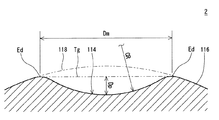
図1は、本発明の一実施形態に係るゴルフボール2が示された一部切り欠き断面図である。ゴルフボール2は、球状コア104と、球状コア104を被覆する中間層106と、前記中間層106を被覆するカバー112とを有する。このカバー112の表面には、多数のディンプル114が形成されている。このゴルフボールの表面のうち、ディンプル114以外の部分は、ランド116である。このゴルフボールは、カバーの外側にペイント層およびマーク層を備えているが、これらの層の図示は省略されている。
FIG. 1 is a partially cutaway sectional view showing a
本発明のゴルフボールは、前記カバーのスラブ硬度は、ショアD硬度で、10以上、好ましくは15以上、より好ましくは20以上であり、75以下、好ましくは73以下、より好ましくは70以下である。カバーの硬度がショアD硬度で75以下であれば、40ヤード〜100ヤード程度の距離のアプローチショットにおけるスピン量が高くなり、コントロール性が向上する。カバーのスラブ硬度とは、カバーを形成するカバー用組成物をシート状に成形して測定したスラブ硬度である。 In the golf ball of the present invention, the slab hardness of the cover is Shore D hardness of 10 or more, preferably 15 or more, more preferably 20 or more, and 75 or less, preferably 73 or less, more preferably 70 or less. . If the cover has a Shore D hardness of 75 or less, the spin rate on approach shots at a distance of about 40 yards to 100 yards increases, and controllability is improved. The slab hardness of the cover is a slab hardness measured by molding the cover composition forming the cover into a sheet shape.
また、特にコントロール性を重視するスピン系のゴルフボールの場合、カバーのスラブ硬度は、ショアD硬度で、10以上が好ましく、より好ましくは15以上、さらに好ましくは20以上であり、55未満が好ましく、より好ましくは50以下、さらに好ましくは45以下である。カバー用組成物のスラブ硬度が、ショアD硬度で55未満であれば、40ヤード〜100ヤード程度の距離のアプローチショットのスピン量が高くなり、グリーン上で止まりやすくなり、かつ、打球感が良好となる。また、スラブ硬度を10以上とすることにより、耐擦過傷性が向上する。 Further, in the case of a spin-type golf ball that emphasizes controllability, the slab hardness of the cover is preferably Shore D hardness of 10 or more, more preferably 15 or more, still more preferably 20 or more, and preferably less than 55. More preferably, it is 50 or less, More preferably, it is 45 or less. If the slab hardness of the cover composition is less than 55 in Shore D hardness, the spin rate of approach shots at a distance of 40 yards to 100 yards will be high, it will be easy to stop on the green, and the shot feel will be good It becomes. Further, by setting the slab hardness to 10 or more, the scratch resistance is improved.
一方、飛距離を重視するディスタンス系のゴルフボールの場合、カバー用組成物のスラブ硬度は、ショアD硬度で55以上が好ましく、より好ましくは58以上、さらに好ましくは60以上であり、75以下が好ましく、より好ましくは73以下、さらに好ましくは70以下である。カバーのスラブ硬度を55以上にすることにより、ドライバーショットおよびロング、ミドルアイアンショットにおいて、高打出角で低スピンのゴルフボールが得られ、飛距離が大きくなる。また、カバー用組成物のスラブ硬度を75以下とすることにより、耐久性に優れたゴルフボールが得られる。 On the other hand, in the case of a distance type golf ball that places importance on the flight distance, the slab hardness of the cover composition is preferably 55 or more, more preferably 58 or more, further preferably 60 or more, and 75 or less in Shore D hardness. More preferably, it is 73 or less, More preferably, it is 70 or less. By setting the slab hardness of the cover to 55 or more, a golf ball having a high launch angle and a low spin can be obtained in a driver shot, a long shot, and a middle iron shot, and the flight distance is increased. Further, by setting the slab hardness of the cover composition to 75 or less, a golf ball having excellent durability can be obtained.
本発明のゴルフボールのカバーを構成するカバー材料としては、特に限定されるものではなく、例えば、アイオノマー樹脂、ポリエステル樹脂、熱可塑性ウレタン樹脂若しくは二液硬化型ウレタン樹脂などのウレタン樹脂、ポリアミド樹脂などの各種樹脂、アルケマ(株)から商品名「ペバックス(登録商標)(例えば、「ペバックス2533」)」で市販されている熱可塑性ポリアミドエラストマー、東レ・デュポン(株)から商品名「ハイトレル(登録商標)(例えば、「ハイトレル3548」、「ハイトレル4047」)」で市販されている熱可塑性ポリエステルエラストマー、BASFジャパン(株)から商品名「エラストラン(登録商標)(例えば、「エラストランXNY90A」、「エラストランXNY97A」、「エラストランXNY585」)」で市販されている熱可塑性ポリウレタンエラストマー、三菱化学(株)から商品名「ラバロン(登録商標)」で市販されている熱可塑性スチレンエラストマーまたは商品名「プリマロイ」で市販されている熱可塑性ポリエステル系エラストマーなどを挙げることができる。前記カバー材料は、単独であるいは2種以上を混合して使用してもよい。 The cover material constituting the golf ball cover of the present invention is not particularly limited. For example, urethane resin such as ionomer resin, polyester resin, thermoplastic urethane resin or two-component curable urethane resin, polyamide resin, etc. Various types of resins, thermoplastic polyamide elastomers marketed by Arkema Co., Ltd. under the trade name "Pebax (registered trademark)" (for example, "Pebax 2533"), trade name "Hytrel (registered trademark)" by Toray DuPont Co., Ltd. ) (For example, “Hytrel 3548”, “Hytrel 4047”) ”, commercially available from BASF Japan, trade name“ Elastollan (registered trademark) ”(for example,“ Elastollan XNY90A ”,“ "Elastolan XNY97A", "Erastra XNY585 ")", a thermoplastic polyurethane elastomer commercially available under the trade name "Lavalon (registered trademark)" from Mitsubishi Chemical Corporation, or a heat commercially available under the trade name "Primalloy" Examples thereof include a plastic polyester elastomer. You may use the said cover material individually or in mixture of 2 or more types.
上述したように、カバーのスラブ硬度を、ショアD硬度で10以上55未満とする場合には、カバー用組成物がポリウレタンを含有することが好ましい。ポリウレタンを使用する場合には、カバー用組成物の樹脂成分中のポリウレタンの含有率は、50質量%以上が好ましく、60質量%以上がより好ましく、70質量%以上がさらに好ましく、90質量%以上が特に好ましい。 As described above, when the slab hardness of the cover is 10 or more and less than 55 in Shore D hardness, it is preferable that the cover composition contains polyurethane. In the case of using polyurethane, the content of polyurethane in the resin component of the cover composition is preferably 50% by mass or more, more preferably 60% by mass or more, further preferably 70% by mass or more, and 90% by mass or more. Is particularly preferred.
前記ポリウレタンは、分子鎖内にウレタン結合を複数有するポリマーであり、例えば、ポリオールとポリイソシアネートとを反応させることにより得られる。必要に応じて、さらに低分子量ポリオールや低分子量ポリアミンなどの鎖延長剤により鎖延長反応がなされていてもよい。 The polyurethane is a polymer having a plurality of urethane bonds in the molecular chain, and is obtained, for example, by reacting a polyol and a polyisocyanate. If necessary, a chain extension reaction may be performed with a chain extender such as a low molecular weight polyol or a low molecular weight polyamine.
前記ポリウレタンを構成するポリイソシアネート成分としては、イソシアネート基を2以上有するものであれば特に限定されず、例えば、2,4−トルエンジイソシアネート、2,6−トルエンジイソシアネート、2,4−トルエンジイソシアネートと2,6−トルエンジイソシアネートの混合物(TDI)、4,4’−ジフェニルメタンジイソシアネート(MDI)、1,5−ナフチレンジイソシアネート(NDI)、3,3’−ビトリレン−4,4’−ジイソシアネート(TODI)、キシリレンジイソシアネート(XDI)、テトラメチルキシリレンジイソシアネート(TMXDI)、パラフェニレンジイソシアネート(PPDI)等の芳香族ポリイソシアネート;4,4’−ジシクロヘキシルメタンジイソシアネート(H12MDI)、水素添加キシリレンジイソシアネート(H6XDI)、ヘキサメチレンジイソシアネート(HDI)、イソホロンジイソシアネート(IPDI)、ノルボルネンジイソシアネート(NBDI)等の脂環式ポリイソシアネートまたは脂肪族ポリイソシアネート等のうちの1種、または、2種以上の混合物などである。
The polyisocyanate component constituting the polyurethane is not particularly limited as long as it has two or more isocyanate groups. For example, 2,4-toluene diisocyanate, 2,6-toluene diisocyanate, 2,4-toluene diisocyanate and 2 , 6-toluene diisocyanate mixture (TDI), 4,4′-diphenylmethane diisocyanate (MDI), 1,5-naphthylene diisocyanate (NDI), 3,3′-vitrylene-4,4′-diisocyanate (TODI), xylylene diisocyanate (XDI), tetramethylxylylene diisocyanate (TMXDI), aromatic polyisocyanates such as p-phenylene diisocyanate (PPDI); 4,4'-dicyclohexylmethane diisocyanate (H 12 MDI), hydrogen added
耐擦過傷性を向上するという観点からは、ポリウレタンのポリイソシアネート成分として、芳香族ポリイソシアネートを使用することが好ましい。芳香族ポリイソシアネートを使用することにより、得られるポリウレタンの機械的特性が向上し、耐擦過傷性に優れるカバーが得られる。また、耐候性を向上するという観点からは、ポリウレタンのポリイソシアネート成分として、非黄変性のポリイソシアネート(TMXDI、XDI、HDI、H6XDI、IPDI、H12MDI、NBDIなど)を使用することが好ましく、さらに好ましくは4,4’−ジシクロヘキシルメタンジイソシアネート(H12MDI)を使用する。4,4’−ジシクロヘキシルメタンジイソシアネート(H12MDI)は剛直な構造を有しており、得られるポリウレタンの機械的特性が向上し、耐擦過傷性に優れるカバーが得られるからである。 From the viewpoint of improving the scratch resistance, it is preferable to use an aromatic polyisocyanate as the polyisocyanate component of the polyurethane. By using the aromatic polyisocyanate, the mechanical properties of the resulting polyurethane are improved, and a cover having excellent scratch resistance can be obtained. From the viewpoint of improving weather resistance, non-yellowing polyisocyanate (TMXDI, XDI, HDI, H 6 XDI, IPDI, H 12 MDI, NBDI, etc.) may be used as the polyisocyanate component of polyurethane. Preferably, more preferably 4,4′-dicyclohexylmethane diisocyanate (H 12 MDI) is used. This is because 4,4′-dicyclohexylmethane diisocyanate (H 12 MDI) has a rigid structure, the mechanical properties of the resulting polyurethane are improved, and a cover having excellent scratch resistance can be obtained.
ポリウレタンを構成するポリオール成分としては、ヒドロキシル基を複数有するものであれば特に限定されず、例えば、鎖延長剤として使用される低分子量ポリオールやソフトセグメントを構成する重合体ポリオールなどを挙げることができる。低分子量のポリオールとしては、例えば、エチレングリコール、ジエチレングリコール、トリエチレングリコール、1,3−ブタンジオール、1,4−ブタンジオール、ネオペンチルグリコール、1,6−ヘキサンジオール等のジオール;グリセリン、トリメチロールプロパン、ヘキサントリオールなどのトリオールが挙げられる。重合体ポリオールとしては、例えば、ポリオキシエチレングリコール(PEG)、ポリオキシプロピレングリコール(PPG)、ポリオキシテトラメチレングリコール(PTMG)等のポリエーテルポリオール;ポリエチレンアジぺート(PEA)、ポリブチレンアジペート(PBA)、ポリヘキサメチレンアジペート(PHMA)などの縮合系ポリエステルポリオール;ポリ−ε−カプロラクトン(PCL)のようなラクトン系ポリエステルポリオール;ポリヘキサメチレンカーボネートなどのポリカーボネートポリオール;及びアクリルポリオールなどが挙げられ、上述したポリオールの少なくとも2種以上の混合物であってもよい。本発明で使用するポリウレタンを構成するポリオール成分は、ポリオキシテトラメチレングリコールであることが好ましい。 The polyol component constituting the polyurethane is not particularly limited as long as it has a plurality of hydroxyl groups, and examples thereof include a low molecular weight polyol used as a chain extender and a polymer polyol constituting a soft segment. . Examples of the low molecular weight polyol include diols such as ethylene glycol, diethylene glycol, triethylene glycol, 1,3-butanediol, 1,4-butanediol, neopentyl glycol, 1,6-hexanediol; glycerin, trimethylol Examples include triols such as propane and hexanetriol. Examples of the polymer polyol include polyether polyols such as polyoxyethylene glycol (PEG), polyoxypropylene glycol (PPG), polyoxytetramethylene glycol (PTMG); polyethylene adipate (PEA), polybutylene adipate ( PBA), condensed polyester polyols such as polyhexamethylene adipate (PHMA); lactone polyester polyols such as poly-ε-caprolactone (PCL); polycarbonate polyols such as polyhexamethylene carbonate; and acrylic polyols, etc. It may be a mixture of at least two or more of the polyols described above. The polyol component constituting the polyurethane used in the present invention is preferably polyoxytetramethylene glycol.
重合体ポリオールの数平均分子量は、特に限定されるものではないが、例えば、400以上であることが好ましく、より好ましくは1,000以上である。重合体ポリオールの数平均分子量が小さくなりすぎると、得られるポリウレタンが硬くなり、ゴルフボールの打球感が低下するからである。重合体ポリオールの数平均分子量の上限は、特に限定されるものではないが、10,000以下、より好ましくは8,000以下である。 The number average molecular weight of the polymer polyol is not particularly limited, but is preferably 400 or more, and more preferably 1,000 or more, for example. This is because if the number average molecular weight of the polymer polyol is too small, the resulting polyurethane becomes hard and the feel at impact of the golf ball decreases. The upper limit of the number average molecular weight of the polymer polyol is not particularly limited, but is 10,000 or less, more preferably 8,000 or less.
必要に応じてポリウレタンを構成し得るポリアミンは、少なくとも2以上のアミノ基を有するものであれば特に限定されない。前記ポリアミンとしては、エチレンジアミン、プロピレンジアミン、ブチレンジアミン、ヘキサメチレンジアミンなどの脂肪族系ポリアミン、イソホロンジアミン、ピペラジンなどの脂環式系ポリアミン、及び、フェニレンジアミン、トルエンジアミン、ジエチルトルエンジアミン、ジメチルチオトルエンジアミン、キシリレンジアミン、ジフェニルメタンジアミンなどの芳香族ポリアミンなどが挙げられる。 The polyamine that can constitute the polyurethane as needed is not particularly limited as long as it has at least two amino groups. Examples of the polyamine include aliphatic polyamines such as ethylenediamine, propylenediamine, butylenediamine and hexamethylenediamine, alicyclic polyamines such as isophoronediamine and piperazine, and phenylenediamine, toluenediamine, diethyltoluenediamine and dimethylthiotoluene. Aromatic polyamines such as diamine, xylylenediamine, and diphenylmethanediamine are exemplified.
また、上述したように、カバーのスラブ硬度を、ショアD硬度で55以上75以下とする場合には、カバー用組成物がアイオノマー樹脂を含有することが好ましい。アイオノマー樹脂を使用する場合には、カバー用組成物の樹脂成分中のアイオノマー樹脂の含有率は、50質量%以上が好ましく、60質量%以上がより好ましく、70質量%以上がさらに好ましい。 As described above, when the slab hardness of the cover is 55 to 75 in Shore D hardness, the cover composition preferably contains an ionomer resin. In the case of using an ionomer resin, the content of the ionomer resin in the resin component of the cover composition is preferably 50% by mass or more, more preferably 60% by mass or more, and further preferably 70% by mass or more.
前記アイオノマー樹脂としては、例えば、オレフィンと炭素数3〜8個のα,β−不飽和カルボン酸との二元共重合体中のカルボキシル基の少なくとも一部を金属イオンで中和したもの、オレフィンと炭素数3〜8個のα,β−不飽和カルボン酸とα,β−不飽和カルボン酸エステルとの三元共重合体のカルボキシル基の少なくとも一部を金属イオンで中和したもの、あるいは、これらの混合物を挙げることができる。前記オレフィンとしては、炭素数が2〜8個のオレフィンが好ましく、例えば、エチレン、プロピレン、ブテン、ペンテン、ヘキセン、ヘプテン、オクテン等を挙げることができ、特にエチレンが好ましい。前記炭素数が3〜8個のα,β−不飽和カルボン酸としては、例えば、アクリル酸、メタクリル酸、フマル酸、マレイン酸、クロトン酸等が挙げられ、特にアクリル酸またはメタクリル酸が好ましい。また、α,β−不飽和カルボン酸エステルとしては、例えば、アクリル酸、メタクリル酸、フマル酸、マレイン酸等のメチル、エチル、プロピル、n−ブチル、イソブチルエステル等が用いられ、特にアクリル酸エステルまたはメタクリル酸エステルが好ましい。これらのなかでも、前記アイオノマー樹脂としては、エチレン−(メタ)アクリル酸二元共重合体の金属イオン中和物、エチレン−(メタ)アクリル酸−(メタ)アクリル酸エステル三元共重合体の金属イオン中和物が好ましい。 Examples of the ionomer resin include a resin obtained by neutralizing at least a part of a carboxyl group in a binary copolymer of an olefin and an α, β-unsaturated carboxylic acid having 3 to 8 carbon atoms with a metal ion. And a ternary copolymer of an α, β-unsaturated carboxylic acid having 3 to 8 carbon atoms and an α, β-unsaturated carboxylic acid ester, wherein at least a part of the carboxyl group is neutralized with a metal ion, or And mixtures thereof. The olefin is preferably an olefin having 2 to 8 carbon atoms, and examples thereof include ethylene, propylene, butene, pentene, hexene, heptene, octene and the like, and ethylene is particularly preferable. Examples of the α, β-unsaturated carboxylic acid having 3 to 8 carbon atoms include acrylic acid, methacrylic acid, fumaric acid, maleic acid, and crotonic acid. Acrylic acid or methacrylic acid is particularly preferable. Examples of the α, β-unsaturated carboxylic acid ester include methyl, ethyl, propyl, n-butyl, isobutyl ester and the like such as acrylic acid, methacrylic acid, fumaric acid and maleic acid, and particularly acrylic acid ester. Or a methacrylic acid ester is preferable. Among these, as the ionomer resin, a metal ion neutralized product of an ethylene- (meth) acrylic acid binary copolymer, an ethylene- (meth) acrylic acid- (meth) acrylic acid ester terpolymer, A metal ion neutralized product is preferred.
前記アイオノマー樹脂の具体例を商品名で例示すると、三井・デュポンポリケミカル(株)から市販されている「ハイミラン(Himilan)(登録商標)(例えば、ハイミラン1555(Na)、ハイミラン1557(Zn)、ハイミラン1605(Na)、ハイミラン1706(Zn)、ハイミラン1707(Na)、ハイミランAM3711(Mg)などが挙げられ、三元共重合体アイオノマー樹脂としては、ハイミラン1856(Na)、ハイミラン1855(Zn)など)」が挙げられる。 Specific examples of the ionomer resin are exemplified by trade names, such as “Himilan (registered trademark)” (for example, Himilan 1555 (Na), Himilan 1557 (Zn), commercially available from Mitsui DuPont Polychemical Co., Ltd., High Milan 1605 (Na), High Milan 1706 (Zn), High Milan 1707 (Na), High Milan AM 3711 (Mg) and the like are listed. Examples of the terpolymer ionomer resins include High Milan 1856 (Na) and High Milan 1855 (Zn). ) ".
さらにデュポン社から市販されているアイオノマー樹脂としては、「サーリン(Surlyn)(登録商標)(例えば、サーリン8945(Na)、サーリン9945(Zn)、サーリン8140(Na)、サーリン8150(Na)、サーリン9120(Zn)、サーリン9150(Zn)、サーリン6910(Mg)、サーリン6120(Mg)、サーリン7930(Li)、サーリン7940(Li)、サーリンAD8546(Li)などが挙げられ、三元共重合体アイオノマー樹脂としては、サーリン8120(Na)、サーリン8320(Na)、サーリン9320(Zn)、サーリン6320(Mg)、HPF1000(Mg)、HPF2000(Mg)など)」が挙げられる。 Further, ionomer resins commercially available from DuPont include “Surlyn (registered trademark)” (for example, Surlyn 8945 (Na), Surlyn 9945 (Zn), Surlyn 8140 (Na), Surlyn 8150 (Na), Surlyn 9120 (Zn), Surlyn 9150 (Zn), Surlyn 6910 (Mg), Surlyn 6120 (Mg), Surlyn 7930 (Li), Surlyn 7940 (Li), Surlyn AD8546 (Li) and the like, and terpolymers Examples of the ionomer resin include Surlyn 8120 (Na), Surlyn 8320 (Na), Surlyn 9320 (Zn), Surlyn 6320 (Mg), HPF1000 (Mg), HPF2000 (Mg), and the like.
またエクソンモービル化学(株)から市販されているアイオノマー樹脂としては、「アイオテック(Iotek)(登録商標)(例えば、アイオテック8000(Na)、アイオテック8030(Na)、アイオテック7010(Zn)、アイオテック7030(Zn)などが挙げられ、三元共重合体アイオノマー樹脂としては、アイオテック7510(Zn)、アイオテック7520(Zn)など)」が挙げられる。 Examples of ionomer resins commercially available from ExxonMobil Chemical Co., Ltd. include “Iotek (registered trademark)” (for example, Iotech 8000 (Na), Iotech 8030 (Na), Iotech 7010 (Zn), Iotech 7030 ( Zn) and the like, and examples of the ternary copolymer ionomer resin include Iotech 7510 (Zn) and Iotech 7520 (Zn)).
なお、前記アイオノマー樹脂の商品名の後の括弧内に記載したNa、Zn、Li、Mgなどは、これらの中和金属イオンの金属種を示している。前記アイオノマー樹脂は、単独で若しくは2種以上を混合して使用しても良い。 Note that Na, Zn, Li, Mg, and the like described in parentheses after the trade name of the ionomer resin indicate the metal species of these neutralized metal ions. The ionomer resins may be used alone or in admixture of two or more.
前記カバーは、上述した樹脂成分のほか、白色顔料(例えば、酸化チタン)、青色顔料、赤色顔料などの顔料成分、炭酸カルシウムや硫酸バリウムなどの比重調整剤、分散剤、老化防止剤、紫外線吸収剤、光安定剤、蛍光材料または蛍光増白剤などを、カバーの性能を損なわない範囲で含有してもよい。 In addition to the resin component described above, the cover includes a pigment component such as a white pigment (for example, titanium oxide), a blue pigment, and a red pigment, a specific gravity adjuster such as calcium carbonate and barium sulfate, a dispersant, an anti-aging agent, and an ultraviolet absorber. An agent, a light stabilizer, a fluorescent material, a fluorescent whitening agent, or the like may be contained as long as the performance of the cover is not impaired.
前記白色顔料(例えば、酸化チタン)の含有量は、カバーを構成する樹脂成分100質量部に対して、0.5質量部以上が好ましく、より好ましくは1質量部以上であって、10質量部以下が好ましく、より好ましくは8質量部以下である。白色顔料の含有量を0.5質量部以上とすることによって、カバーに隠蔽性を付与することができる。また、白色顔料の含有量が10質量部超になると、得られるカバーの耐久性が低下する場合があるからである。 The content of the white pigment (for example, titanium oxide) is preferably 0.5 parts by mass or more, more preferably 1 part by mass or more, and 10 parts by mass with respect to 100 parts by mass of the resin component constituting the cover. The following is preferable, and more preferably 8 parts by mass or less. By setting the content of the white pigment to 0.5 parts by mass or more, the cover can be concealed. Moreover, it is because durability of the cover obtained may fall when content of a white pigment exceeds 10 mass parts.
カバー用組成物を用いてカバーを成形する態様は、特に限定されないが、カバー用組成物をコア上に直接射出成形する態様、あるいは、カバー用組成物から中空殻状のシェルを成形し、コアを複数のシェルで被覆して圧縮成形する態様(好ましくは、カバー用組成物から中空殻状のハーフシェルを成形し、コアを2枚のハーフシェルで被覆して圧縮成形する方法)を挙げることができる。カバーが成形されたゴルフボール本体は、金型から取り出し、必要に応じて、バリ取り、洗浄、サンドブラストなどの表面処理を行うことが好ましい。また、所望により、マークを形成することもできる。 Although the aspect which shape | molds a cover using the composition for a cover is not specifically limited, the aspect which directly inject-molds the composition for a cover on a core, or shape | molds a hollow shell-like shell from a composition for a cover, and a core And a method of compression molding by coating with a plurality of shells (preferably a method of molding a hollow shell-shaped half shell from a cover composition and coating a core with two half shells) Can do. The golf ball body in which the cover is molded is preferably taken out from the mold and subjected to surface treatment such as deburring, washing, and sandblasting as necessary. Moreover, a mark can be formed if desired.
カバーに形成されるディンプルの総数は、200個以上500個以下が好ましい。ディンプルの総数が200個未満では、ディンプルの効果が得られにくい。また、ディンプルの総数が500個を超えると、個々のディンプルのサイズが小さくなり、ディンプルの効果が得られにくい。形成されるディンプルの形状(平面視形状)は、特に限定されるものではなく、円形;略三角形、略四角形、略五角形、略六角形などの多角形;その他不定形状;を単独で使用してもよいし、2種以上を組合せて使用してもよい。 The total number of dimples formed on the cover is preferably 200 or more and 500 or less. If the total number of dimples is less than 200, the dimple effect is difficult to obtain. Further, when the total number of dimples exceeds 500, the size of each dimple becomes small and it is difficult to obtain the dimple effect. The shape (plan view shape) of the dimple formed is not particularly limited, and a circular shape; a polygon such as a substantially triangular shape, a substantially square shape, a substantially pentagonal shape, or a substantially hexagonal shape; Alternatively, two or more kinds may be used in combination.
本発明において、全てのディンプルの面積の合計の仮想球の表面積に対する比率は、占有率と称される。仮想球とは、ディンプルが存在しないとしたときのゴルフボール(球体)である。本発明のゴルフボールにおいて、ディンプルの占有率は、60%以上が好ましく、63%以上がより好ましく、66%以上がさらに好ましく、95%以下が好ましく、92%以下がより好ましく、89%以下がさらに好ましい。占有率が高くなりすぎると、後述する摩擦係数に対する塗膜の寄与が小さくなる。また、占有率が小さすぎると、飛行性能が低下する。 In the present invention, the ratio of the total area of all the dimples to the surface area of the phantom sphere is called an occupation ratio. A virtual sphere is a golf ball (sphere) when no dimples are present. In the golf ball of the present invention, the dimple occupation ratio is preferably 60% or more, more preferably 63% or more, further preferably 66% or more, preferably 95% or less, more preferably 92% or less, and 89% or less. Further preferred. When the occupation ratio becomes too high, the contribution of the coating film to the friction coefficient described later becomes small. Further, if the occupation ratio is too small, the flight performance is deteriorated.
なお、ディンプルの面積は、無限遠からゴルフボールの中心を見た場合の、輪郭線に囲まれた領域の面積である。円形ディンプルの場合、面積Sは下記数式によって算出される。
S=(Dm/2)2・π (Dm:ディンプルの直径)
The area of the dimple is the area of the region surrounded by the contour line when the center of the golf ball is viewed from infinity. In the case of a circular dimple, the area S is calculated by the following mathematical formula.
S = (Dm / 2) 2 · π (Dm: Dimple diameter)
図2には、ディンプル114の中心及びゴルフボール2の中心を通過する平面に沿った断面が示されている。図2における上下方向は、ディンプル114の深さ方向である。図2において二点鎖線118で示されているのは、仮想球である。仮想球の表面は、ディンプル114が存在しないと仮定されたときのゴルフボール2の表面である。ディンプル114は、仮想球の表面から凹陥している。ランド116は、仮想球の表面と一致している。本実施形態では、ディンプル114の断面形状は、実質的には円弧である。
FIG. 2 shows a cross section along a plane passing through the center of the
図2において両矢印Dmで示されているのは、ディンプル114の直径である。この直径Dmは、ディンプル114の両側に共通の接線Tgが画かれたときの、一方の接点Edと他方の接点Edとの距離である。接点Edは、ディンプル114のエッジでもある。エッジEdは、ディンプル114の輪郭を画定する。図2において両矢印Dpで示されているのは、ディンプル114の深さである。この深さDpは、ディンプル114の最深部と接線Tgとの距離である。
In FIG. 2, the diameter of the
ディンプルの直径Dmは、2.0mm以上6.0mm以下が好ましい。直径Dmが2.0mm以上であるディンプルは、乱流化に寄与する。この観点から、直径Dmは2.2mm以上がより好ましく、2.4mm以上が特に好ましい。直径Dmが6.0mm以下であるディンプルは、実質的に球であるというゴルフボール2の本質を損なわない。この観点から、直径Dmは5.8mm以下がより好ましく、5.6mm以下が特に好ましい。
The diameter Dm of the dimple is preferably 2.0 mm or greater and 6.0 mm or less. Dimples having a diameter Dm of 2.0 mm or more contribute to turbulence. In this respect, the diameter Dm is more preferably equal to or greater than 2.2 mm, and particularly preferably equal to or greater than 2.4 mm. Dimples having a diameter Dm of 6.0 mm or less do not impair the essence of the
図2において矢印CRで示されているのは、ディンプル114の曲率半径である。曲率半径CRは、下記数式(1)によって算出される。
CR=(Dp2+Dm2/4)/(2×Dp) (1)
その断面形状が円弧でないディンプル114の場合でも、上記数式(1)に基づいて、近似的に曲率半径CRが算出される。
In FIG. 2, what is indicated by an arrow CR is the radius of curvature of the
CR = (Dp 2 + Dm 2 /4) / (2 × Dp) (1)
Even in the case of the
十分な占有率が達成されるとの観点から、ディンプルの総数は300個以上が好ましく、310個以上がより好ましく、320個以上が特に好ましい。個々のディンプルが乱流化に寄与しうるとの観点から、総数は500個以下が好ましく、490個以下がより好ましく、480個以下が特に好ましい。 In light of achieving a sufficient occupation ratio, the total number of dimples is preferably 300 or more, more preferably 310 or more, and particularly preferably 320 or more. From the viewpoint that individual dimples can contribute to turbulence, the total number is preferably 500 or less, more preferably 490 or less, and particularly preferably 480 or less.
本発明において「ディンプルの容積」とは、ディンプルの輪郭を含む平面とディンプルの表面とに囲まれた部分の容積を意味する。ゴルフボール2のホップが抑制されるとの観点から、ディンプルの総容積は250mm3以上が好ましく、260mm3以上がより好ましく、270mm3以上が特に好ましい。ゴルフボール2のドロップが抑制されるとの観点から、総容積は450mm3以下が好ましく、440mm3以下がより好ましく、430mm3以下が特に好ましい。
In the present invention, “dimple volume” means the volume of a portion surrounded by a plane including the outline of the dimple and the surface of the dimple. From the viewpoint of rising of the
ゴルフボール2のホップが抑制されるとの観点から、ディンプル114の深さDpは0.05mm以上が好ましく、0.08mm以上がより好ましく、0.10mm以上が特に好ましい。ゴルフボール2のドロップが抑制されるとの観点から、深さDpは0.60mm以下が好ましく、0.45mm以下がより好ましく、0.40mm以下が特に好ましい。
In light of suppression of hops in the
ゴルフボールの直径は、40mm〜45mmが好ましい。米国ゴルフ協会(USGA)の規格が満たされるとの観点から、直径は、42.67mm以上が好ましい。空気抵抗の観点から、直径は44mm以下が好ましく、42.80mm以下がより好ましい。ゴルフボールの質量は、40g以上50g以下が好ましい。大きな慣性が得られるとの観点から、質量は44g以上が好ましく、45.00g以上がより好ましい。USGAの規格が満たされるとの観点から、質量は45.93g以下が好ましい。 The diameter of the golf ball is preferably 40 mm to 45 mm. From the viewpoint of satisfying the standards of the US Golf Association (USGA), the diameter is preferably 42.67 mm or more. In light of air resistance, the diameter is preferably equal to or less than 44 mm, and more preferably equal to or less than 42.80 mm. The weight of the golf ball is preferably 40 g or more and 50 g or less. From the viewpoint of obtaining a large inertia, the mass is preferably 44 g or more, and more preferably 45.00 g or more. From the viewpoint that the USGA standard is satisfied, the mass is preferably equal to or less than 45.93 g.
次に、糸巻きゴルフボール、ツーピースゴルフボールおよびマルチピースゴルフボールに用いられるコアについて説明する。 Next, the core used for the wound golf ball, the two-piece golf ball, and the multi-piece golf ball will be described.
前記コアには、公知のゴム組成物(以下、単に「コア用ゴム組成物」という場合がある)を用いることができ、例えば、基材ゴム、共架橋剤および架橋開始剤を含むゴム組成物を加熱プレスして成形することができる。 A known rubber composition (hereinafter sometimes simply referred to as “core rubber composition”) may be used for the core. For example, a rubber composition containing a base rubber, a co-crosslinking agent, and a crosslinking initiator. Can be formed by hot pressing.
前記基材ゴムとしては、特に、反発に有利なシス結合が40質量%以上、好ましくは70質量%以上、より好ましくは90質量%以上のハイシスポリブタジエンを用いることが好ましい。前記共架橋剤としては、炭素数が3〜8個のα,β−不飽和カルボン酸またはその金属塩が好ましく、アクリル酸の金属塩またはメタクリル酸の金属塩がより好ましい。金属塩の金属としては、亜鉛、マグネシウム、カルシウム、アルミニウム、ナトリウムが好ましく、より好ましくは亜鉛である。共架橋剤の使用量は、基材ゴム100質量部に対して20質量部以上50質量部以下が好ましい。架橋開始剤としては、有機過酸化物が好ましく用いられる。具体的には、ジクミルパーオキサイド、1,1−ビス(t−ブチルパーオキシ)−3,3,5−トリメチルシクロヘキサン、2,5−ジメチル−2,5−ジ(t―ブチルパーオキシ)ヘキサン、ジ−t−ブチルパーオキサイドなどの有機過酸化物が挙げられ、これらのうちジクミルパーオキサイドが好ましく用いられる。架橋開始剤の配合量は、基材ゴム100質量部に対して、0.2質量部以上が好ましく、より好ましくは0.3質量部以上であって、3質量部以下が好ましく、より好ましくは2質量部以下である。また、前記コア用ゴム組成物は、さらに、有機硫黄化合物を含有してもよい。前記有機硫黄化合物としては、ジフェニルジスルフィド類、チオフェノール類、チオナフトール類を好適に使用することができる。有機硫黄化合物の配合量は、基材ゴム100質量部に対して、0.1質量部以上が好ましく、より好ましくは0.3質量部以上であって、5.0質量部以下が好ましく、より好ましくは3.0質量部以下である。前記コア用ゴム組成物は、さらにカルボン酸および/またはその塩を含有してもよい。カルボン酸および/またはその塩としては、炭素数が1〜30のカルボン酸および/またはその塩が好ましい。カルボン酸および/またはその塩の配合量は、基材ゴム100質量部に対して、1質量部以上、40質量部以下が好ましい。 As the base rubber, it is particularly preferable to use a high-cis polybutadiene having a cis bond advantageous for rebound of 40% by mass or more, preferably 70% by mass or more, and more preferably 90% by mass or more. The co-crosslinking agent is preferably an α, β-unsaturated carboxylic acid having 3 to 8 carbon atoms or a metal salt thereof, more preferably a metal salt of acrylic acid or a metal salt of methacrylic acid. As the metal of the metal salt, zinc, magnesium, calcium, aluminum, and sodium are preferable, and zinc is more preferable. The amount of the co-crosslinking agent used is preferably 20 parts by mass or more and 50 parts by mass or less with respect to 100 parts by mass of the base rubber. As the crosslinking initiator, an organic peroxide is preferably used. Specifically, dicumyl peroxide, 1,1-bis (t-butylperoxy) -3,3,5-trimethylcyclohexane, 2,5-dimethyl-2,5-di (t-butylperoxy) Organic peroxides such as hexane and di-t-butyl peroxide can be mentioned, and among them, dicumyl peroxide is preferably used. The amount of the crosslinking initiator is preferably 0.2 parts by mass or more, more preferably 0.3 parts by mass or more, and preferably 3 parts by mass or less, more preferably 100 parts by mass of the base rubber. 2 parts by mass or less. The rubber composition for a core may further contain an organic sulfur compound. As the organic sulfur compound, diphenyl disulfides, thiophenols, and thionaphthols can be preferably used. The compounding amount of the organic sulfur compound is preferably 0.1 parts by mass or more, more preferably 0.3 parts by mass or more, and preferably 5.0 parts by mass or less with respect to 100 parts by mass of the base rubber. Preferably it is 3.0 mass parts or less. The core rubber composition may further contain a carboxylic acid and / or a salt thereof. The carboxylic acid and / or salt thereof is preferably a carboxylic acid having 1 to 30 carbon atoms and / or a salt thereof. The compounding amount of the carboxylic acid and / or salt thereof is preferably 1 part by mass or more and 40 parts by mass or less with respect to 100 parts by mass of the base rubber.
前記コア用ゴム組成物には、基材ゴム、共架橋剤、架橋開始剤、有機硫黄化合物に加えて、さらに、酸化亜鉛や硫酸バリウムなどの重量調整剤、老化防止剤、色粉などを適宜配合することができる。前記コア用ゴム組成物の加熱プレス成型条件は、ゴム組成に応じて適宜設定すればよいが、通常、130℃〜200℃で10分間〜60分間加熱するか、あるいは130℃〜150℃で20分間〜40分間加熱した後、160℃〜180℃で5分間〜15分間と2段階加熱することが好ましい。コアは、単層コアでよいし、センターと包囲層とからなる2層コアでもよい。 In addition to the base rubber, co-crosslinking agent, cross-linking initiator, and organic sulfur compound, the core rubber composition further contains a weight adjusting agent such as zinc oxide and barium sulfate, an anti-aging agent, and color powder as appropriate. Can be blended. The hot-press molding conditions for the core rubber composition may be appropriately set according to the rubber composition, but are usually heated at 130 ° C. to 200 ° C. for 10 minutes to 60 minutes, or at 130 ° C. to 150 ° C. for 20 minutes. After heating for 40 minutes for 40 minutes, it is preferable to heat at 160 ° C. to 180 ° C. for 5 minutes to 15 minutes. The core may be a single-layer core or a two-layer core composed of a center and an envelope layer.
本発明のゴルフボールが、3ピース、4ピースゴルフボール、5ピースゴルフボール以上のマルチピースゴルフボールである場合には、コアと最外層カバーとの間に設ける中間層としては、例えば、ポリウレタン樹脂、アイオノマー樹脂、ポリアミド樹脂、ポリエチレンなどの熱可塑性樹脂;スチレンエラストマー、ポリオレフィンエラストマー、ポリウレタンエラストマー、ポリエステルエラストマーなどの熱可塑性エラストマー;ゴム組成物の硬化物などが挙げられる。ここで、アイオノマー樹脂としては、例えば、エチレンとα,β−不飽和カルボン酸との共重合体中のカルボキシル基の少なくとも一部を金属イオンで中和したもの、またはエチレンとα,β−不飽和カルボン酸とα,β−不飽和カルボン酸エステルとの三元共重合体中のカルボキシル基の少なくとも一部を金属イオンで中和したものが挙げられる。前記中間層には、さらに、硫酸バリウム、タングステンなどの比重調整剤、老化防止剤、顔料などが配合されていてもよい。なお、中間層は、ゴルフボールの構成に応じて、内側カバー層や、外層コアと称される場合がある。 When the golf ball of the present invention is a 3-piece, 4-piece golf ball, or multi-piece golf ball of 5 pieces or more, the intermediate layer provided between the core and the outermost cover is, for example, a polyurethane resin. And thermoplastic resins such as ionomer resins, polyamide resins, and polyethylene; thermoplastic elastomers such as styrene elastomers, polyolefin elastomers, polyurethane elastomers, and polyester elastomers; and cured products of rubber compositions. Here, examples of the ionomer resin include those obtained by neutralizing at least a part of carboxyl groups in a copolymer of ethylene and α, β-unsaturated carboxylic acid with metal ions, or ethylene and α, β-unsaturated. What neutralized at least one part of the carboxyl group in the ternary copolymer of saturated carboxylic acid and (alpha), (beta)-unsaturated carboxylic acid ester with a metal ion is mentioned. The intermediate layer may further contain a specific gravity adjusting agent such as barium sulfate or tungsten, an antiaging agent, or a pigment. The intermediate layer may be referred to as an inner cover layer or an outer layer core depending on the configuration of the golf ball.
本発明のゴルフボールは、ゴルフボール本体とゴルフボール本体表面に設けられた塗膜とを有するゴルフボールであって、接触力試験機を用いて算出した摩擦係数が、0.35以上、0.60以下であることが好ましい。 The golf ball of the present invention is a golf ball having a golf ball main body and a coating film provided on the surface of the golf ball main body, and the friction coefficient calculated using a contact force tester is 0.35 or more,. It is preferable that it is 60 or less.
本発明において、接触力試験機を用いて算出する摩擦係数は、ゴルフボールの飛行方向に対して、所定の角度で傾斜して設置された衝突板に、ゴルフボールを衝突させたときのゴルフボールと衝突板の摩擦係数である。接触力試験機により、衝突板に垂直な方向の接触力の時間関数Fn(t)および衝突板に平行な方向の接触力の時間関数Ft(t)を同時に求め、次の式で定義される両者の比の時間関数M(t)の最大値を、摩擦係数して求める。
M(t)=Ft(t)/Fn(t)
In the present invention, the friction coefficient calculated using the contact force tester is the golf ball when the golf ball collides with the collision plate installed at a predetermined angle with respect to the flight direction of the golf ball. And the friction coefficient of the collision plate. A contact force tester simultaneously calculates a contact force time function Fn (t) in a direction perpendicular to the collision plate and a contact force time function Ft (t) in a direction parallel to the collision plate, and is defined by the following equation: The maximum value of the time function M (t) of the ratio between the two is obtained as a friction coefficient.
M (t) = Ft (t) / Fn (t)
本発明における摩擦係数の算出方法を、図3〜図5に基づいて説明する。図3は、摩擦係数を測定するための接触力試験機である。図4は、ゴルフボールを衝突させる衝突板4の拡大断面図である。
The calculation method of the friction coefficient in this invention is demonstrated based on FIGS. FIG. 3 is a contact force tester for measuring the friction coefficient. FIG. 4 is an enlarged cross-sectional view of the
前記接触力試験機1は、ゴルフボールをクラブフェースで打撃する状態を擬似的に作り出してそのときの各種の力を測定することができる。接触力試験機1は、例えば垂直上向きにゴルフボール2を発射しうる発射装置5と、発射されたゴルフボール2の上部に位置することにより、前記ゴルフボール2と衝突する打撃面3を有する衝突板4とを含んでいる。
The
発射装置5と打撃面3との距離が比較的小さいので、ゴルフボール2の初速度は、前記衝突速度に相当する。また、この衝突速度は、実際のゴルフスイングにおいて、クラブヘッドのヘッドスピードに対応している。このような点に鑑み、ゴルフボール2と打撃面3との衝突速度は、例えば約10m/s〜50m/s程度の範囲の中から設定しうる。本発明では、アプローチショットのヘッドスピードを考慮して、初速度を19m/秒とした。
Since the distance between the launching
前記ゴルフボール2の初速度は、コントローラ6のボリューム等によって目標値が設定される。また、発射装置5に設けられた第1センサS1と第2センサS2との間の距離と、このセンサを遮断する時間差とを用いて、コントローラ6はゴルフボール2の初速度の実測値を計算し、かつ、コンピュータ装置PC等に出力できる。
A target value of the initial velocity of the
図4には、衝突板4の拡大部分断面図が示される。前記衝突板4は、ゴルフボール2の発射方向(飛行方向)に対して任意の角度αで打撃面3を傾けることができる。本発明では、90度からこの角度αを差し引いた角度θを衝突角度とする。この衝突角度θは、実際のスイングにおいてクラブフェース(図示せず)のロフト角に対応している。また、上記衝突角度θは、例えば10°〜90°の範囲の中からゴルフクラブのロフト角を考慮して複数の値(例えば、15゜、20゜、35゜等)が設定され、それぞれで後述の接触力の測定を行うことができる。本発明では、アプローチショットのスピン量を再現するために、衝突角度θを55°とした。
FIG. 4 shows an enlarged partial sectional view of the
前記衝突板4は、例えば金属製の板材からなるベース板4aと、前記打撃面3を構成する表層板4cと、これらの間に挟まれた圧力センサ4bとを具え、これらは互いにボルト4dで一体に固着される。
The
前記ベース板4aは所定強度と剛性を有するものであればよく、その材質は、特に制限されないが、好ましくはスチールが用いられる。ベース板4aの厚みは、5.0mm〜20.0mmであることが好ましい。また、JIS規格による主ボルト4dの型番は、例えばM10である。 The base plate 4a has only to have predetermined strength and rigidity, and the material is not particularly limited, but steel is preferably used. The thickness of the base plate 4a is preferably 5.0 mm to 20.0 mm. The model number of the main bolt 4d according to the JIS standard is, for example, M10.
前記圧力センサ4bは、例えば、3成分力センサが好適に使用される。このようなセンサは、少なくとも、打撃面3と垂直な方向の垂直力Fnと、打撃面3に平行な方向(クラブフェースではソール側からクラウン側の方向)のせん断力Ftとを時系列データとして測定できる。また、力の測定は、圧力センサ4bにチャージアンプ等を接続して行われる。
For example, a three-component force sensor is preferably used as the
圧力センサ4bには、各種製品が使用できるが、例えば、キスラー社の3成分力センサ(型式9067)が使用される。このセンサは、平行な方向、Y方向及び垂直な方向の力の成分を測定できる。圧力の測定は、図示されていないが、圧力センサ4bにチャージアンプ(キスラー社の型式5011B)を接続して行われる。圧力センサ4bの中心には貫通孔が形成され、この貫通孔に主ボルト4dを挿入して圧力センサ4bはベース板4aに固着一体化させている。
Various products can be used for the
前記表層板4cは、本体4c1と、その外側に配されることにより打撃面3に表れかつゴルフボール2と衝突するのに十分な面積を持った表層材4c2とから構成される。これらは、図示しないボルト等を用いて脱着自在に固着されている。従って、表層材4c2の材料、表面形状及び/又は表面構造を任意に変更することにより、各種のクラブフェースの近似的モデルを作成してその接触力を測定できる。
The surface layer plate 4c is composed of a main body 4c1 and a surface layer material 4c2 having an area sufficient to appear on the
本体4c1の材料は限定されないが、一般的にはステンレススチール(SUS−630)が使用される。本体4c1の厚みは、通常10mm〜20mmである。また、本体4c1の平面形状は圧力センサ4bの平面形状と実質的に同一とすることができ、例えば、一辺が40mm〜60mmの正方形である。本体4c1には主ボルト4dの先端が螺入されている。これによってベース板4aと本体4c1との間に圧力センサ4bが挟まれその位置が固定される。
The material of the main body 4c1 is not limited, but generally stainless steel (SUS-630) is used. The thickness of the main body 4c1 is usually 10 mm to 20 mm. Moreover, the planar shape of the main body 4c1 can be made substantially the same as the planar shape of the
衝突板4の打撃面3をなす表層材4c2は、各種材料、表面形状及び表面構造が採用できるが、解析対象として予め設定されたゴルフクラブヘッドのフェース(図示省略)と同一の材料で形成されるのが良い。本発明では、アプローチショットのモデルを評価する観点から、前記表層材4c2は、例えば、クリーブランドゴルフ社のCG−15のヘッド材料と同一の材料であるSUS−431ステンレスを使用した。表層材4c2の厚みは、任意に変更できるが、例えば、1.0mm〜5.0mmである。また、表層材4c2の平面形状は前記本体4c1の平面形状と実質的に同一寸法とし、例えば、一辺が40mm〜60mmの正方形とすることができる。
The surface layer material 4c2 forming the
さらに、接触力試験機1は、打撃面3とゴルフボール2との衝突及び衝突して跳ね返るゴルフボール2を撮影しうるストロボ装置7及びハイスピード型のカメラ装置8を含んでいる。前記ストロボ装置7は、ストロボ電源9に接続される。また、カメラ装置8は、コンデンサボックスを介してカメラ電源10に接続されている。そして、撮像されたデータは、前記コンピュータ装置PC等に記憶される。これらの機器を含ませることにより、後述するゴルフボール2と打撃面3との衝突時のすべり速度や、接触面積、ゴルフボールの打ち出し速度、打ち出し角度及びバックスピン量などを測定することができる。
Further, the
図5には、上記接触力試験機1で測定された一条件のゴルフボール2と打撃面3との衝突時に打撃面3が受けた垂直力Fnとせん断力Ftとの時刻歴が示される。
FIG. 5 shows a time history of the normal force Fn and the shear force Ft received by the
図5は、図3及び図4の測定装置で測定されるFn(t)及びFt(t)の一例が示されたグラフである。図5において、点P0は圧力センサ4bが力を感知し始める点であり、打撃面3とゴルフボール2との衝突開始時にほぼ相当する。そして垂直な方向の接触力であるFn(t)は点P0から徐々に増加し、点P4で最高値となり、ここから減少して点P3でゼロとなる。この点P3は、圧力センサ4bが力を感知しなくなった点であり、打撃面3からゴルフボール2が離れた時点にほぼ相当する。
FIG. 5 is a graph showing an example of Fn (t) and Ft (t) measured by the measuring apparatus of FIGS. 3 and 4. In FIG. 5, a point P <b> 0 is a point at which the
一方、衝突板に平行な方向の接触力(すなわちせん断力)であるFt(t)の値は時間経過と共に点P0から増加し点P1で最高値となり、それから減少して点P2でゼロとなり、それ以降は負の値となる。点P3でゴルフボールが圧力センサ4bから離れるので、圧力センサ4bで感知されるFt(t)のカーブは点P3でゼロとなる。Ft(t)のカーブと時間軸とで囲まれた領域のうちFt(t)が正の値をとる領域の面積S1は、せん断力が正である力積を表す。一方、Ft(t)のカーブと時間軸とで囲まれた領域のうちFt(t)が負の値をとる領域の面積S2は、せん断力が負である力積を表す。力積S1はバックスピンを促進する方向に作用し、力積S2はバックスピンを抑制する方向に作用する。ここで、力積S1は力積S2よりも大きい値をとり、力積S1から力積S2を減じた値が、ゴルフボールのバックスピンに寄与する。
On the other hand, the value of Ft (t), which is the contact force in the direction parallel to the collision plate (that is, shear force), increases from point P0 with time, reaches the maximum value at point P1, then decreases to zero at point P2, After that, it becomes a negative value. Since the golf ball is separated from the
そして摩擦係数として求めるには、Ft(t)/Fn(t)で得られるM(t)の最大値を算出することで得ることができる。 The friction coefficient can be obtained by calculating the maximum value of M (t) obtained by Ft (t) / Fn (t).
本発明では、前記のようにして求めた摩擦係数が、0.35以上が好ましく、0.37以上がより好ましく、0.39以上がさらに好ましく、0.60以下が好ましく、0.56以下がより好ましく、0.54以下がさらに好ましい。摩擦係数が、前記範囲内であれば、アプローチショットのスピン量が良好になる。 In the present invention, the friction coefficient obtained as described above is preferably 0.35 or more, more preferably 0.37 or more, further preferably 0.39 or more, preferably 0.60 or less, and 0.56 or less. More preferred is 0.54 or less. If the friction coefficient is within the above range, the spin amount of the approach shot becomes good.
以下、本発明を実施例によって詳細に説明するが、本発明は、下記実施例によって限定されるものではなく、本発明の趣旨を逸脱しない範囲の変更、実施の態様は、いずれも本発明の範囲内に含まれる。 Hereinafter, the present invention will be described in detail by way of examples. However, the present invention is not limited to the following examples, and all modifications and embodiments without departing from the gist of the present invention are not limited thereto. Included in range.
[評価方法]
(1)スラブ硬度(ショアD硬度)
カバー用組成物を用いて、射出成形により、厚み約2mmのシートを作製し、23℃で2週間保存した。このシートを、測定基板などの影響が出ないように、3枚以上重ねた状態で、ASTM−D2240に規定するスプリング式硬度計ショアD型を備えた高分子計器社製自動ゴム硬度計P1型を用いて測定した。
[Evaluation method]
(1) Slab hardness (Shore D hardness)
Using the cover composition, a sheet having a thickness of about 2 mm was produced by injection molding and stored at 23 ° C. for 2 weeks. An automatic rubber hardness tester P1 type manufactured by Kobunshi Keiki Co., Ltd. equipped with a spring type hardness tester Shore D type as defined in ASTM-D2240 in a state where three or more sheets are stacked so as not to affect the measurement substrate. It measured using.
(2)摩擦係数の測定
図3、4に示す接触力試験機を用いて、ゴルフボールの摩擦係数を測定した。
1.測定装置の仕様
(A)発射装置:エアガン方式
(B)衝突板 :
ベース板4a
スチール
厚さ:5.35mm
表層板4c
本体4c1
サイズ :56mm×56mm×15mm
ステンレススチール(SUS−630)
表層材4c2
サイズ :56mm×56mm×2.5mm
金属組成:SUS−431
溝形状:図6参照
傾斜角度(α)
35度(ゴルフボールの飛行方向に対して)
(C)圧力センサ4b
キスラー社の3成分力センサ(型式9067)
チャージアンプ
キスラー社の型式5011B
(D)接触力のPCへの取り込み
パルスカウンタボード PCI−6101(インターフェイス社製)を用いた。16ビット4チャンネルを持つPCIパルスカウンタボードで、4種類のカウンタモードで用途に合った計測が実現できる。最大入力周波数は1MHz。
(2) Measurement of friction coefficient The friction coefficient of the golf ball was measured using the contact force tester shown in FIGS.
1. Specification of measuring device (A) Launcher: Air gun type (B) Colliding plate:
Base plate 4a
Steel thickness: 5.35mm
Surface plate 4c
Body 4c1
Size: 56mm x 56mm x 15mm
Stainless steel (SUS-630)
Surface material 4c2
Size: 56mm x 56mm x 2.5mm
Metal composition: SUS-431
Groove shape: See FIG. 6 Inclination angle (α)
35 degrees (relative to golf ball flight direction)
(C)
Kistler's three-component force sensor (model 9067)
Charge amplifier Kistler Model 5011B
(D) Incorporation of contact force into PC Pulse counter board PCI-6101 (manufactured by Interface Corporation) was used. A PCI pulse counter board with 16 bits and 4 channels can be used for measurement in 4 different counter modes. The maximum input frequency is 1MHz.
図6に示したように、衝突板4の打撃面3(図3参照)には、クリーブランド社製サンドウエッジCG−15の溝構造を再現している。図6(a)に示すように、打撃面3には、大きな溝(ジップグルーブ)と、大きな溝(ジップグルーブ)間の表面に、小さな溝が複数設けられている。図6(b)は、ジップグルーブの断面構造の拡大図である。ジップグルーブの寸法は、下記の通りである。
ジップグルーブ(溝)幅W:0.70mm
ジップグルーブ(溝)深さh:0.50mm
ジップグルーブ(溝)ピッチ:3.56mm
ジップグルーブ(溝)角度α:10°
ジップグルーブ肩R:0.25
ジップグルーブ間の複数の小さな溝は、ジップグルーブ間の表面部分が、表面粗さRa=2.40±0.8μm、Rmax=14.0±8μmになるように、レーザーミーリングにより形成されている。なお、表面粗さRa、Rmaxは、表面粗さ測定機(ミツトヨ社製、「SJ−301」)を用いて、測定長さ=2.5mm、カットオフ値=2.5mmの測定条件で測定する。
As shown in FIG. 6, a groove structure of a sand wedge CG-15 manufactured by Cleveland is reproduced on the striking surface 3 (see FIG. 3) of the
Zip groove width W: 0.70mm
Zip groove (groove) depth h: 0.50 mm
Zip groove pitch: 3.56mm
Zip groove angle α: 10 °
Zip groove shoulder R: 0.25
The plurality of small grooves between the zip grooves are formed by laser milling so that the surface portion between the zip grooves has a surface roughness Ra = 2.40 ± 0.8 μm and Rmax = 14.0 ± 8 μm. . The surface roughness Ra and Rmax were measured using a surface roughness measuring machine (“SJ-301” manufactured by Mitutoyo Corporation) under the measurement conditions of measurement length = 2.5 mm and cut-off value = 2.5 mm. To do.
2.測定手順
摩擦係数の測定は次の方法で行った。
(a)衝突板の角度(α)をゴルフボールの飛行方向(垂直方向)に対して、35度に設定した。
(b)発射装置5のエア圧を調整する。
(c)発射装置からゴルフボールを発射する。
(d)予め設定したセンサS1とセンサS2(図3参照)の距離とこの間のゴルフボールの遮蔽時間差からゴルフボール初速度を測定する。ゴルフボール初速度は19m/sとなるように調整した。
(e)接触力Fn(t)、接触力Ft(t)を測定し、Ft(t)/Fn(t)の最大値を算出する。
2. Measurement procedure The coefficient of friction was measured by the following method.
(A) The angle (α) of the collision plate was set to 35 degrees with respect to the flight direction (vertical direction) of the golf ball.
(B) The air pressure of the
(C) A golf ball is launched from the launching device.
(D) The initial velocity of the golf ball is measured from the preset distance between the sensor S1 and the sensor S2 (see FIG. 3) and the golf ball shielding time difference therebetween. The initial velocity of the golf ball was adjusted to 19 m / s.
(E) The contact force Fn (t) and the contact force Ft (t) are measured, and the maximum value of Ft (t) / Fn (t) is calculated.
3.測定結果
前記試験装置、測定手順で測定された結果の一例を図7に示す。図7からM(t)の値は、Ft(t)/Fn(t)として算出され、その最大値は0.58となる。なおFt、Fnは接触力の立ち上がる初期と終期においてノイズが発生しやすいので、初期の前段階、終期の後段階をトリムしてM(t)の最大値を算出する。
3. Measurement Results FIG. 7 shows an example of the results measured by the test apparatus and measurement procedure. From FIG. 7, the value of M (t) is calculated as Ft (t) / Fn (t), and its maximum value is 0.58. Since Ft and Fn are likely to generate noise at the initial stage and the final stage when the contact force rises, the maximum value of M (t) is calculated by trimming the initial stage and the final stage.
(3)塗膜のマルテンス硬度
エリオニクス社製のナノインデンター「ENT−2100」を用いて測定した。
測定条件は、以下の通りである。
荷重F:20mgf
バーコビッチ圧子の角度α:65.03°
バーコビッチ圧子の材質:SiO2
押し込み深さhと圧子の角度αとに基づいて、下記数式によって面積As(h)が算出される。
As(h)=3×31/2×tanα/cosα×h2
荷重Fと面積As(h)に基づいて、下記数式によってマルテンス硬度が算出される。
マルテンス硬度=F/As(h)
測定サンプル:主剤および硬化剤を配合した塗料を40℃で4時間乾燥及び硬化をさせて、厚みが100μmの塗膜シートを作製して、測定に用いた。
(3) Martens hardness of the coating film Measured using a nanoindenter “ENT-2100” manufactured by Elionix.
The measurement conditions are as follows.
Load F: 20 mgf
Berkovich indenter angle α: 65.03 °
Barkovic indenter material: SiO 2
Based on the indentation depth h and the indenter angle α, the area As (h) is calculated by the following mathematical formula.
As (h) = 3 × 3 1/2 × tan α / cos α × h 2
Based on the load F and the area As (h), the Martens hardness is calculated by the following mathematical formula.
Martens hardness = F / As (h)
Measurement sample: The coating material containing the main agent and the curing agent was dried and cured at 40 ° C. for 4 hours to prepare a coating sheet having a thickness of 100 μm and used for measurement.
(4)塗膜の機械的物性
主剤および硬化剤を配合した塗料を40℃で4時間乾燥及び硬化をさせて塗膜を作製した。JIS−K7161に準じて、この塗膜をダンベル形状に打ち抜いて試験片を作製し、引張試験測定装置(島津製作所製)を用いて塗膜の物性を測定し、10%伸長時のモジュラスを算出した。
試験片の膜厚:0.05mm
引張速度:50mm/分
(4) Mechanical properties of the coating film The coating material containing the main agent and the curing agent was dried and cured at 40 ° C. for 4 hours to prepare a coating film. According to JIS-K7161, this coating film is punched into a dumbbell shape to produce a test piece, and the physical properties of the coating film are measured using a tensile test measuring device (manufactured by Shimadzu Corporation), and the modulus at 10% elongation is calculated. did.
Film thickness of test piece: 0.05mm
Tensile speed: 50 mm / min
(5)動的粘弾性の測定
塗膜の貯蔵弾性率E’(dyn/cm2)および損失正接(tanδ)を以下の条件で測定した。
装置:ユービーエム社製動的粘弾性測定装置Rheogel−E4000
測定サンプル:主剤および硬化剤を配合した塗料を40℃で4時間乾燥及び硬化をさせて、厚み0.11mm−0.14mmの塗膜フィルムを作製した。この塗膜フィルムから、幅4mm、クランプ間距離20mmになるように試料片を切り出した。
測定モード:引張
測定温度:−50℃〜150℃
昇温速度:4℃/分
測定データ取り込み間隔:4℃
加振周波数:10Hz
測定歪み:0.1%
120℃の貯蔵弾性率E’120には、測定データ取り込みを4℃間隔とし、測定温度が120℃以上の温度で、最初にデータを取り込んだ貯蔵弾性率の値を採用した。150℃の貯蔵弾性率E’150には、測定データ取り込みを4℃間隔とし、測定温度が150℃以下の温度で、最後にデータを取り込んだ貯蔵弾性率の値を採用した。10℃の損失正接(tanδ)には、測定データ取り込みを4℃間隔とし、測定温度が10℃以上の温度で、最初にデータを取り込んだ損失正接の値を採用した。
(5) Measurement of dynamic viscoelasticity The storage elastic modulus E ′ (dyn / cm 2 ) and loss tangent (tan δ) of the coating film were measured under the following conditions.
Apparatus: Dynamic viscoelasticity measuring apparatus Rheogel-E4000 manufactured by UBM Co., Ltd.
Measurement sample: The paint containing the main agent and the curing agent was dried and cured at 40 ° C. for 4 hours to prepare a coating film having a thickness of 0.11 mm to 0.14 mm. A sample piece was cut out from this coating film so as to have a width of 4 mm and a distance between clamps of 20 mm.
Measurement mode: Tensile Measurement temperature: -50 ° C to 150 ° C
Temperature rise rate: 4 ° C / min Measurement data capture interval: 4 ° C
Excitation frequency: 10 Hz
Measurement distortion: 0.1%
As the storage elastic modulus E ′ 120 at 120 ° C., the measured data was taken at 4 ° C. intervals, and the value of the storage elastic modulus at which the data was first acquired at a measurement temperature of 120 ° C. or higher was adopted. For the storage elastic modulus E ′ 150 of 150 ° C., the value of the storage elastic modulus at which the data was last taken at the measurement temperature of 150 ° C. or less was adopted at the intervals of 4 ° C. for the measurement data. For the loss tangent (tan δ) at 10 ° C., the measurement data was taken at 4 ° C. intervals, and the value of the loss tangent at which the data was first taken at a measurement temperature of 10 ° C. or higher was adopted.
(6)アプローチショットのスピン量(21m/s:40ヤード〜100ヤードのショットに相当)
ツルーテンパー社製スイングロボットM/Cに、サンドウエッジ(クリーブランドゴルフ社製CG15フォージドウエッジ(52°))を取り付け、ヘッドスピード21m/秒でゴルフボールを打撃し、打撃されたゴルフボールを連続写真撮影することによってスピン量(rpm)を測定した。測定は、各ゴルフボールについて10回ずつ行い、その平均値をスピン量とした。なお、ゴルフボールNo.1〜18のスピン量は、ゴルフボールNo.11のスピン量との差で示した。
(6) Spin amount of approach shot (21 m / s: equivalent to 40 yards to 100 yards shot)
Sand Wedge (CG15 Forged Wedge (52 °) manufactured by Cleveland Golf Co., Ltd.) is attached to TrueTemper's swing robot M / C, and a golf ball is hit at a head speed of 21 m / sec. The shot golf ball is photographed continuously. As a result, the spin rate (rpm) was measured. The measurement was performed 10 times for each golf ball, and the average value was defined as the spin amount. Golf ball No. The spin amount of 1 to 18 is the golf ball No. The difference from the spin amount of 11 is shown.
(7)アプローチショットのスピン量(10m/s:40ヤード未満のショットに相当)
ツルーテンパー社製スイングロボットM/Cに、サンドウエッジ(クリーブランドゴルフ社製CG15フォージドウエッジ(52°))を取り付け、ヘッドスピード10m/秒でゴルフボールを打撃し、打撃されたゴルフボールを連続写真撮影することによってスピン量(rpm)を測定した。測定は、各ゴルフボールについて10回ずつ行い、その平均値をスピン量とした。打出角は、スイングロボットM/Cの打球方向前方に設けた線状レーザ光源による光のスクリーンを、ボールが通過するときの影を一次元CCDセンサで計測した。なお、ゴルフボールNo.1〜18のスピン量、打出角は、ゴルフボールNo.11との差で、ゴルフボールNo.19〜34のスピン量、打出角は、ゴルフボールNo.26との差で示した。
(7) Approach shot spin rate (10 m / s: equivalent to shots less than 40 yards)
Sand Wedge (CG15 Forged Wedge (52 °) manufactured by Cleveland Golf Co., Ltd.) is attached to a swing robot M / C manufactured by True Temper, and a golf ball is hit at a head speed of 10 m / sec, and the shot golf ball is photographed continuously. As a result, the spin rate (rpm) was measured. The measurement was performed 10 times for each golf ball, and the average value was defined as the spin amount. As for the launch angle, a one-dimensional CCD sensor was used to measure a shadow when a ball passed through a screen of light from a linear laser light source provided in front of the swing direction of the swing robot M / C. Golf ball No. The spin amount and launch angle of 1 to 18 were measured according to golf ball No. Golf ball no. The spin amount and launch angle of 19 to 34 are the same as those of golf ball no. It is shown by the difference from 26.
(8)ドライバーショットのスピン量
ツルーテンパー社製のスイングロボットM/Cに、チタンヘッドを備えたドライバー(ダンロップスポーツ社製、XXIO S ロフト10.0°)を取り付け、ヘッドスピード45m/秒でゴルフボールを打撃し、打撃直後のゴルフボールのスピン量を測定した。測定は、各ゴルフボールについて10回ずつ行って、その平均値をそのゴルフボールの測定値とした。なお、打撃直後のゴルフボールのスピン量は、打撃されたゴルフボールを連続写真撮影することによって測定した。なお、ゴルフボールNo.19〜34のスピン量は、ゴルフボールNo.26との差で示した。
(8) Spin rate of driver shot A driver equipped with a titanium head (Dunlop Sports, XXIO S Loft 10.0 °) is attached to a swing robot M / C manufactured by Trutemper, and golf is played at a head speed of 45 m / sec. The ball was hit and the spin amount of the golf ball immediately after hitting was measured. The measurement was performed 10 times for each golf ball, and the average value was taken as the measured value of the golf ball. Note that the spin amount of the golf ball immediately after hitting was measured by taking continuous photographs of the hit golf ball. Golf ball No. The spin amount of 19 to 34 is the golf ball No. It is shown by the difference from 26.
(9)打球感
アマチュアゴルファー(上級者)10人により、サンドウエッジ(クリーブランドゴルフ社製、CG15フォージドウエッジ(52°))を用いた実打テストを行った。フィーリング良好(フェースに乗っている感じがして良い、ひっかかる感じがして良い、スピンがきく感じがして良い、くっつく感じがして良い等)と答えた人数に基づいて、以下の様に評価した。
◎:9人以上
○:6人〜8人
△:3人〜5人
×:2人以下
(9) Hit feeling A real hit test using a sand wedge (CG15 forged wedge (52 °) manufactured by Cleveland Golf Co., Ltd.) was conducted by 10 amateur golfers (advanced players). Based on the number of people who answered that they had a good feeling (it feels like they are on the face, they can feel snags, they feel like they are spinning, they feel good) Evaluated.
◎: 9 or more ○: 6 to 8 △: 3 to 5 ×: 2 or less
[ゴルフボールの作製]
(1)センター用組成物の作製
表1に示す配合の材料を混練し、センター用組成物を作製した。
[Production of golf balls]
(1) Preparation of center composition Materials having the composition shown in Table 1 were kneaded to prepare a center composition.
ZNDA−90S:日本蒸溜工業社製、アクリル酸亜鉛(10質量%ステアリン酸亜鉛コーティング品)
サンセラーSR:三新化学工業社製、アクリル酸亜鉛(10質量%ステアリン酸コーティング品)
酸化亜鉛:東邦亜鉛社製、「銀嶺R」
硫酸バリウム:堺化学社製、「硫酸バリウムBD」
ジフェニルジスルフィド:住友精化社製
2−チオナフトール:東京化成工業社
ビス(ペンタブロモフェニル)ジスルフィド:川口化学工業社
オクタン酸亜鉛:三津和化学薬品社
ジクミルパーオキサイド:日油社製、「パークミル(登録商標)D」
ZNDA-90S: manufactured by Nippon Distilled Industries Co., Ltd., zinc acrylate (10% by weight zinc stearate coated product)
Suncellor SR: Sanshin Chemical Industry Co., Ltd., zinc acrylate (10% by mass stearic acid coating product)
Zinc oxide: Toho Zinc Co., Ltd.
Barium sulfate: Sakai Chemical Co., Ltd. “Barium sulfate BD”
Diphenyl disulfide: Sumitomo Seika Chemical Co., Ltd. 2-thionaphthol: Tokyo Chemical Industry Co., Ltd. Bis (pentabromophenyl) disulfide: Kawaguchi Chemical Co., Ltd. Zinc Octanoate: Mitsuwa Chemicals Co., Ltd. Dicumyl peroxide: NOF Corporation, "Park Mill" (Registered trademark) D "
(2)中間層用組成物およびカバー用組成物の調製
表2、表3に示した配合の材料を、二軸混練型押出機によりミキシングして、ペレット状の中間層用組成物およびカバー用組成物を調製した。押出条件は、スクリュー径45mm、スクリュー回転数200rpm、スクリューL/D=35であり、配合物は、押出機のダイの位置で200〜260℃に加熱された。
(2) Preparation of intermediate layer composition and cover composition The materials shown in Tables 2 and 3 were mixed with a twin-screw kneading extruder to form a pellet-like intermediate layer composition and cover. A composition was prepared. The extrusion conditions were a screw diameter of 45 mm, a screw rotation speed of 200 rpm, and a screw L / D = 35.
ハイミランAM7329:三井デュポンポリケミカル社製、亜鉛イオン中和エチレン−メタクリル酸共重合体アイオノマー樹脂
ハイミランAM7337:三井デュポンポリケミカル社製、ナトリウムイオン中和エチレン−メタクリル酸共重合体系アイオノマー樹脂
エラストランXNY97A:BASFジャパン社製、熱可塑性ポリウレタンエラストマー
ラバロンT3221C:三菱化学社製、熱可塑性ポリスチレンエラストマー
チヌビン770:BASFジャパン社製、ヒンダードアミン系安定剤
エラストランXNY75A:BASFジャパン社製、熱可塑性ポリウレタンエラストマー
エラストランXNY80A:BASFジャパン社製、熱可塑性ポリウレタンエラストマー
エラストランXNY82A:BASFジャパン社製、熱可塑性ポリウレタンエラストマー
エラストランXNY83A:BASFジャパン社製、熱可塑性ポリウレタンエラストマー
エラストランXNY85A:BASFジャパン社製、熱可塑性ポリウレタンエラストマー
エラストランXNY95A:BASFジャパン社製、熱可塑性ポリウレタンエラストマー
ハイミラン1706:三井・デュポンポリケミカル社製、亜鉛イオン中和エチレン−メタクリル酸共重合体系アイオノマー樹脂
ハイミラン1555:三井・デュポンポリケミカル社製、ナトリウムイオン中和エチレン−メタクリル酸共重合体系アイオノマー樹脂
サーリン8945:デュポン社製、ナトリウムイオン中和エチレン−メタクリル酸共重合体系アイオノマー樹脂
ハイミランAM7329:三井・デュポンポリケミカル社製、亜鉛イオン中和エチレン−メタクリル酸共重合体系アイオノマー樹脂
ハイミランAM7337:三井デュポンポリケミカル社製、ナトリウムイオン中和エチレン−メタクリル酸共重合体系アイオノマー樹脂
ノバミッドST220:三菱エンジニアリングプラスチックス社製、ポリアミド樹脂(高
衝撃グレード、曲げ弾性率:2000MPa)
ニュクレルN1050H:三井・デュポンポリケミカル社製、エチレン−メタクリル酸共重合体
チヌビン770:BASFジャパン社製、ヒンダードアミン系安定剤
Nukurel N1050H: Mitsui DuPont Polychemical Co., Ltd., ethylene-methacrylic acid copolymer Tinuvin 770: BASF Japan Co., Ltd., hindered amine stabilizer
(3)ゴルフボール本体の作製
(3−1)ゴルフボールNo.1〜16、19〜32
センター用組成物No.Aを混練し、半球状キャビティを有する上下金型内で170℃、20分間加熱プレスすることにより直径39.3mmの球状センターを得た。
(3) Production of Golf Ball Body (3-1) Golf Ball No. 1-16, 19-32
Center composition No. A was kneaded and heated and pressed at 170 ° C. for 20 minutes in an upper and lower mold having a hemispherical cavity to obtain a spherical center having a diameter of 39.3 mm.
上記で得た中間層用組成物No.Aを、前述のようにして得た球状センター上に直接射出成形することにより、前記センターを被覆する中間層(厚さ1.0mm)を形成した。成形用上下型は、半球状キャビティと、球状センターを支持する進退可能なホールドピンとを有している。中間層成形時には、上記ホールドピンを突き出し、センターを投入後ホールドさせ、80トンの圧力で型締めした金型に260℃に加熱した中間層用組成物を0.3秒で注入し、30秒間冷却して型開きした。 Intermediate layer composition No. obtained above. A was directly injection molded on the spherical center obtained as described above, thereby forming an intermediate layer (thickness: 1.0 mm) covering the center. The upper and lower molds for molding have a hemispherical cavity and a hold pin that can move back and forth to support the spherical center. At the time of forming the intermediate layer, the hold pin is protruded, the center is inserted and held, and the intermediate layer composition heated to 260 ° C. is injected into the mold clamped at a pressure of 80 tons in 0.3 seconds, and 30 seconds. The mold was opened after cooling.
ハーフシェルの圧縮成形は、得られたペレット状のカバー用組成物(表5〜8に示す)をハーフシェル成形用金型の下型の凹部ごとに1つずつ投入し、加圧してハーフシェルを成形した。圧縮成形は、成形温度170℃、成形時間5分、成形圧力2.94MPaの条件で行った。 For compression molding of the half shell, the obtained pellet-shaped cover composition (shown in Tables 5 to 8) is charged one by one for each concave portion of the lower mold of the half shell molding die, and pressed to form a half shell. Was molded. The compression molding was performed under the conditions of a molding temperature of 170 ° C., a molding time of 5 minutes, and a molding pressure of 2.94 MPa.
上記で得られた中間層被覆球体を上記で得られた2枚のハーフシェルで同心円状に被覆して、圧縮成形によりカバーを成形した。圧縮成形は、成形温度145℃、成形時間2分、成形圧力9.8MPaの条件で行った。 The intermediate layer-coated sphere obtained above was concentrically covered with the two half shells obtained above, and a cover was formed by compression molding. The compression molding was performed under the conditions of a molding temperature of 145 ° C., a molding time of 2 minutes, and a molding pressure of 9.8 MPa.
(3−2)ゴルフボールNo.17
センター用組成物No.Bを、共に半球状キャビティを備えた上型及び下型からなる金型に投入し、170℃の温度下で25分間加熱して、直径が39.5mmである球状センターを得た。金型に、球状センターを投入し、上記で得た中間層用組成物No.Bを、射出成形法にて球状センターの周りに射出し、第一中間層(厚さ1.0mm)を成形した。上記で得た中間層用組成物No.Cから、圧縮成形法にてハーフシェルを成形し、このハーフシェルから圧縮成形法にて第一中間層を被覆する第二中間層(厚さ0.3mm)を形成した。カバー用組成物No.kから、圧縮成形法にてハーフシェルを成形し、このハーフシェルから圧縮成形法にて第二中間層を被覆するカバー(厚さ0.3mm)を形成した。
(3-2) Golf Ball No. 17
Center composition No. B was put into a mold composed of an upper mold and a lower mold each having a hemispherical cavity, and heated at 170 ° C. for 25 minutes to obtain a spherical center having a diameter of 39.5 mm. A spherical center was introduced into the mold, and the intermediate layer composition no. B was injected around the spherical center by an injection molding method to form a first intermediate layer (thickness: 1.0 mm). Intermediate layer composition No. obtained above. From C, a half shell was formed by compression molding, and a second intermediate layer (thickness 0.3 mm) covering the first intermediate layer was formed from this half shell by compression molding. Cover composition No. From k, a half shell was molded by a compression molding method, and a cover (thickness 0.3 mm) covering the second intermediate layer was formed from the half shell by a compression molding method.
(3−3)ゴルフボールNo.18
センター用組成物No.Cを、共に半球状キャビティを備えた上型及び下型からなる金型に投入し、170℃の温度下で25分間加熱して、直径が15mmである球状センターを得た。上記で得たセンター用組成物No.Dから、圧縮成形法にてハーフシェルを成形し、このハーフシェルから圧縮成形法にて球状センターを被覆する包囲層(厚さ12.25mm)を形成した。次いで、上記ゴルフボールNo.17と同様に、第一中間層(厚さ1.0mm)、第二中間層(厚さ0.3mm)カバー(厚さ0.3mm)を形成した。
(3-3) Golf Ball No. 18
Center composition No. C was put into a mold composed of an upper mold and a lower mold each having a hemispherical cavity and heated at a temperature of 170 ° C. for 25 minutes to obtain a spherical center having a diameter of 15 mm. Center composition No. obtained above. From D, a half shell was formed by compression molding, and an envelope layer (thickness 12.25 mm) covering the spherical center was formed from this half shell by compression molding. Subsequently, the golf ball No. Similarly to 17, a first intermediate layer (thickness 1.0 mm), a second intermediate layer (thickness 0.3 mm) and a cover (thickness 0.3 mm) were formed.
(3−4)ゴルフボールNo.33
センター用組成物No.Eを、共に半球状キャビティを備えた上型及び下型からなる金型に投入し、170℃の温度下で25分間加熱して、直径が37.9mmである球状センターを得た。金型に、球状センターを投入し、上記で得た中間層用組成物No.Dを、射出成形法にて球状センターの周りに射出し、第一中間層(厚さ0.8mm)を成形した。さらに、上記で得た中間層用組成物No.Eを、射出成形法にて第一中間層の周りに射出し、第二中間層(厚さ0.8mm)を成形した。最後に、上記で得たカバー用組成物No.lを、射出成形法にて第二中間層の周りに射出し、カバー(厚さ0.8mm)を成形した。
(3-4) Golf Ball No. 33
Center composition No. E was put into a mold composed of an upper mold and a lower mold each having a hemispherical cavity and heated at 170 ° C. for 25 minutes to obtain a spherical center having a diameter of 37.9 mm. A spherical center was introduced into the mold, and the intermediate layer composition no. D was injected around the spherical center by an injection molding method to form a first intermediate layer (thickness 0.8 mm). Furthermore, composition No. for intermediate | middle layer obtained above was used. E was injected around the first intermediate layer by injection molding to form a second intermediate layer (thickness 0.8 mm). Finally, the cover composition No. obtained above. l was injected around the second intermediate layer by injection molding to form a cover (thickness 0.8 mm).
(3−5)ゴルフボールNo.34
センター用組成物No.Eを、共に半球状キャビティを備えた上型及び下型からなる金型に投入し、170℃の温度下で25分間加熱して、直径が36.3mmである球状センターを得た。金型に、球状センターを投入し、上記で得た中間層用組成物No.Dを、射出成形法にて球状センターの周りに射出し、第一中間層(厚さ0.8mm)を成形した。次に、上記で得た中間層用組成物No.Eを、射出成形法にて第一中間層の周りに射出し、第二中間層(厚さ0.8mm)を成形した。さらに、上記で得た中間層用組成物No.Fを、射出成形法にて第二中間層の周りに射出し、第三中間層(厚さ0.8mm)を成形した。最後に、上記で得たカバー用組成物No.lを、射出成形法にて第三中間層の周りに射出し、カバー(厚さ0.8mm)を成形した。
(3-5) Golf Ball No. 34
Center composition No. E was put into a mold composed of an upper mold and a lower mold each having a hemispherical cavity and heated at 170 ° C. for 25 minutes to obtain a spherical center having a diameter of 36.3 mm. A spherical center was introduced into the mold, and the intermediate layer composition no. D was injected around the spherical center by an injection molding method to form a first intermediate layer (thickness 0.8 mm). Next, the intermediate layer composition No. obtained above was obtained. E was injected around the first intermediate layer by injection molding to form a second intermediate layer (thickness 0.8 mm). Furthermore, composition No. for intermediate | middle layer obtained above was used. F was injected around the second intermediate layer by an injection molding method to form a third intermediate layer (thickness 0.8 mm). Finally, the cover composition No. obtained above. l was injected around the third intermediate layer by injection molding to form a cover (thickness 0.8 mm).
(4)塗料の調製
表4に示したポリオールとポリイソシアネートとを配合して塗料を調製した。なお、主剤は、メチルエチルケトン、酢酸n−ブチル、トルエンの混合溶媒を用いて、ポリオール成分の濃度が30質量%になるように調整した。硬化剤は、溶媒として、メチルエチルケトン、トルエンの混合溶媒を用いて、ポリイソシアネート成分の濃度が60質量%になるように調整した。得られた塗料について、塗膜の物性を測定し、表5〜8に示した。また、各塗料についての動的粘弾性スペクトルを図9〜13に示し、各塗料の貯蔵弾性率(E’)と温度との関係を図14、各塗料の損失正接(tanδ)と温度との関係を図15に示した。
(4) Preparation of paint A paint was prepared by blending the polyol shown in Table 4 and polyisocyanate. In addition, the main ingredient was adjusted so that the density | concentration of a polyol component might be 30 mass% using the mixed solvent of methyl ethyl ketone, n-butyl acetate, and toluene. The curing agent was adjusted so that the concentration of the polyisocyanate component was 60% by mass using a mixed solvent of methyl ethyl ketone and toluene as a solvent. About the obtained coating material, the physical property of the coating film was measured and it showed to Tables 5-8. Moreover, the dynamic viscoelastic spectrum about each coating material is shown in FIGS. 9-13, the relationship between the storage elastic modulus (E ') and temperature of each coating material is shown in FIG. 14, the loss tangent (tan δ) of each coating material and temperature. The relationship is shown in FIG.
表4で用いた原料は、以下の通りである。
主剤
神東塗料社製ポリン#950:水酸基価128mgKOH/g、ポリオール成分(トリメチロールプロパン、ポリオキシテトラメチレングリコール)と、ポリイソシアネート成分(イソホロンジイソシアネート)とからなるウレタンポリオール
硬化剤
HDI(ヘキサメチレンジイソシアネート)のビュレット変性体:旭化成ケミカルズ社製、「デュラネート(登録商標)21S−75E」(NCO含有率:15.5%)
HDI(ヘキサメチレンジイソシアネート)のイソシアヌレート変性体:旭化成ケミカルズ社製、「デュラネートTKA−100」(NCO含有率:21.7%)
IPDI(イソホロンジイソシアネート)のイソシアヌレート体:デグサ社製、「VESTANAT(登録商標) T1890」(NCO含有率:12.0%)
The raw materials used in Table 4 are as follows.
Prin # 950 manufactured by Shinto Paint Co., Ltd .: urethane polyol curing agent HDI (hexamethylene diisocyanate) comprising a hydroxyl value of 128 mgKOH / g, a polyol component (trimethylolpropane, polyoxytetramethylene glycol) and a polyisocyanate component (isophorone diisocyanate) ) Modified burette: "Duranate (registered trademark) 21S-75E" manufactured by Asahi Kasei Chemicals Corporation (NCO content: 15.5%)
Modified isocyanurate of HDI (hexamethylene diisocyanate): “Duranate TKA-100” manufactured by Asahi Kasei Chemicals Corporation (NCO content: 21.7%)
Isocyanurate of IPDI (isophorone diisocyanate): manufactured by Degussa, “VESTANAT (registered trademark) T1890” (NCO content: 12.0%)
(5)塗膜の形成
(3)で得られたゴルフボール本体の表面をサンドブラスト処理して、マーキングを施した後、スプレーガンで塗料を塗布し、40℃のオーブンで24時間塗料を乾燥させ、直径42.7mmのゴルフボールを得た。塗膜の厚さは、ゴルフボールNo.1〜13、17〜29、32〜34は20μm、ゴルフボールNo.14、30は30μm、ゴルフボールNo.15、31は40μmとした。塗装は、図8に示した回転体にゴルフボール本体を載置し、回転体を300rpmで回転させ、ゴルフボール本体からエアーガンを吹き付け距離(7cm)だけ離間させて上下方向に移動させながら行った。重ね塗りの各回のインターバルを1.0秒とした。エアーガンの吹付条件は、吹付エアー圧;0.15MPa、圧送タンクエアー圧;0.10MPa、1回の塗布時間;1秒、雰囲気温度;20℃〜27℃、雰囲気湿度;65%以下の条件で塗装とした。得られたゴルフボールについて評価した結果を併せて表5〜8に示した。
(5) Formation of coating film After the surface of the golf ball body obtained in (3) is sandblasted and marked, the paint is applied with a spray gun and dried in an oven at 40 ° C. for 24 hours. A golf ball having a diameter of 42.7 mm was obtained. The thickness of the coating film was determined according to Golf Ball No. 1-13, 17-29, 32-34 are 20 micrometers, golf ball No.1. 14 and 30 are 30 μm, golf ball No. 15 and 31 were 40 micrometers. The coating was performed by placing the golf ball body on the rotating body shown in FIG. 8, rotating the rotating body at 300 rpm, and blowing the air gun away from the golf ball body by a distance of 7 cm and moving it up and down. . The interval of each overcoating was 1.0 second. The air gun spraying conditions were as follows: spraying air pressure: 0.15 MPa, pressure tank air pressure: 0.10 MPa, one application time: 1 second, ambient temperature: 20 ° C. to 27 ° C., ambient humidity: 65% or less Painted. The result evaluated about the obtained golf ball was collectively shown in Tables 5-8.
表5〜8の結果より、塗膜の120℃〜150℃の温度範囲における貯蔵弾性率(E’)が、1.00×10⁷dyn/cm2以上、1.00×108dyn/cm2以下であり、10℃における損失正接(tanδ)が0.050以上、かつ、カバーのスラブ硬度が10以上75以下であるゴルフボールは、40ヤード未満のアプローチショット、特にグリーン周り(10〜20ヤード程度)からのアプローチショットにおけるコントロール性が向上していることが分かる。 From the results of Tables 5 to 8, the storage elastic modulus (E ′) in the temperature range of 120 ° C. to 150 ° C. of the coating film is 1.00 × 10 7 dyn / cm 2 or more, 1.00 × 10 8 dyn / cm. A golf ball having a loss tangent (tan δ) at 10 ° C. of 0.050 or more and a cover slab hardness of 10 or more and 75 or less is approach shot of less than 40 yards, particularly around the green (10-20) It can be seen that the controllability in approach shots from the yard level is improved.
本発明は、塗装ゴルフボールに好適に適用できる。 The present invention can be suitably applied to a painted golf ball.
1:接触力試験機、2:ゴルフボール、3:打撃面、4:衝突板、5:発射装置、6:コントローラ、7:ストロボ装置、8:ハイスピード型カメラ装置、9:ストロボ電源、10:カメラ電源、Fn:打撃面と垂直な方向の垂直力、Ft:打撃面と平行な方向の剪断力、21:回転体、23a〜23c:プロング、25:エアーガン、104:内層コア、106:外層コア、107:球状コア、108:中間層、110:補強層、112:カバー、114:ディンプル、116:ランド
1: contact force tester, 2: golf ball, 3: striking surface, 4: collision plate, 5: launching device, 6: controller, 7: strobe device, 8: high-speed camera device, 9: strobe power supply, 10 : Camera power supply, Fn: Normal force in a direction perpendicular to the striking surface, Ft: Shear force in a direction parallel to the striking surface, 21: Rotating body, 23a-23c: Prong, 25: Air gun, 104: Inner core, 106: Outer core, 107: Spherical core, 108: Intermediate layer, 110: Reinforcement layer, 112: Cover, 114: Dimple, 116: Land
Claims (21)
前記塗膜は、動的粘弾性装置により下記条件にて測定した120℃〜150℃の温度範囲における貯蔵弾性率(E’)が、1.00×10⁷dyn/cm2以上、1.00×108dyn/cm2以下、かつ、10℃における損失正接(tanδ)が、0.050以上であり、
前記カバーのスラブ硬度が、ショアDで、10以上75以下であることを特徴とするゴルフボール。
<測定条件>
測定モード:引張
測定温度:−50℃〜150℃
昇温速度:4℃/分
加振周波数:10Hz
測定歪み:0.1% A golf ball comprising a golf ball body comprising a core and at least one cover covering the core, and a coating film provided on the surface of the golf ball body,
The coating film has a storage elastic modulus (E ′) in a temperature range of 120 ° C. to 150 ° C. measured by a dynamic viscoelasticity device under the following conditions, 1.00 × 10 7 dyn / cm 2 or more, 1.00 × 10 8 dyn / cm 2 or less, and loss tangent (tan δ) at 10 ° C. is 0.050 or more,
A golf ball having a slab hardness of 10 to 75 in Shore D.
<Measurement conditions>
Measurement mode: Tensile Measurement temperature: -50 ° C to 150 ° C
Temperature increase rate: 4 ° C / min Excitation frequency: 10Hz
Measurement distortion: 0.1%
The golf ball according to claim 1, wherein the coating film has a thickness of 10 μm or more and 50 μm or less.
Priority Applications (5)
| Application Number | Priority Date | Filing Date | Title |
|---|---|---|---|
| JP2012136296A JP6057556B2 (en) | 2012-06-10 | 2012-06-15 | Golf ball |
| US13/908,488 US9259618B2 (en) | 2012-06-10 | 2013-06-03 | Golf ball |
| KR1020130064460A KR101418217B1 (en) | 2012-06-10 | 2013-06-05 | Golf ball |
| EP13170884.4A EP2671619B1 (en) | 2012-06-10 | 2013-06-06 | Golf ball |
| CN201310226880.XA CN103480128B (en) | 2012-06-10 | 2013-06-07 | Golf |
Applications Claiming Priority (3)
| Application Number | Priority Date | Filing Date | Title |
|---|---|---|---|
| JP2012131448 | 2012-06-10 | ||
| JP2012131448 | 2012-06-10 | ||
| JP2012136296A JP6057556B2 (en) | 2012-06-10 | 2012-06-15 | Golf ball |
Publications (2)
| Publication Number | Publication Date |
|---|---|
| JP2014014384A true JP2014014384A (en) | 2014-01-30 |
| JP6057556B2 JP6057556B2 (en) | 2017-01-11 |
Family
ID=50109671
Family Applications (1)
| Application Number | Title | Priority Date | Filing Date |
|---|---|---|---|
| JP2012136296A Active JP6057556B2 (en) | 2012-06-10 | 2012-06-15 | Golf ball |
Country Status (1)
| Country | Link |
|---|---|
| JP (1) | JP6057556B2 (en) |
Cited By (8)
| Publication number | Priority date | Publication date | Assignee | Title |
|---|---|---|---|---|
| JP5823578B1 (en) * | 2014-06-27 | 2015-11-25 | ダンロップスポーツ株式会社 | Golf ball |
| JP2016123582A (en) * | 2014-12-26 | 2016-07-11 | ダンロップスポーツ株式会社 | Golf ball and method for manufacturing the same |
| EP3135346A1 (en) * | 2015-08-25 | 2017-03-01 | Dunlop Sports Co., Ltd. | Golf ball |
| EP3492150A1 (en) * | 2017-11-29 | 2019-06-05 | Sumitomo Rubber Industries, Ltd. | Golf ball |
| EP3492149A1 (en) * | 2017-11-29 | 2019-06-05 | Sumitomo Rubber Industries, Ltd. | Golf ball |
| EP3669955A1 (en) * | 2018-12-19 | 2020-06-24 | Sumitomo Rubber Industries, Ltd. | Golf ball |
| JP2020099669A (en) * | 2018-12-19 | 2020-07-02 | 住友ゴム工業株式会社 | Golf ball |
| US11173349B2 (en) | 2017-11-29 | 2021-11-16 | Sumitomo Rubber Industries, Ltd. | Golf ball |
Citations (6)
| Publication number | Priority date | Publication date | Assignee | Title |
|---|---|---|---|---|
| JPH08182775A (en) * | 1994-12-28 | 1996-07-16 | Sumitomo Rubber Ind Ltd | Painted golf ball |
| JPH09276445A (en) * | 1996-04-17 | 1997-10-28 | Bridgestone Sports Co Ltd | Golf ball |
| JPH10137367A (en) * | 1996-11-13 | 1998-05-26 | Sumitomo Rubber Ind Ltd | Golf ball |
| JP2000254249A (en) * | 1999-03-05 | 2000-09-19 | Sumitomo Rubber Ind Ltd | Manufacture of golf ball |
| JP2001017574A (en) * | 1999-07-06 | 2001-01-23 | Sumitomo Rubber Ind Ltd | Golf ball |
| JP2011217820A (en) * | 2010-04-06 | 2011-11-04 | Sri Sports Ltd | Golf ball |
-
2012
- 2012-06-15 JP JP2012136296A patent/JP6057556B2/en active Active
Patent Citations (6)
| Publication number | Priority date | Publication date | Assignee | Title |
|---|---|---|---|---|
| JPH08182775A (en) * | 1994-12-28 | 1996-07-16 | Sumitomo Rubber Ind Ltd | Painted golf ball |
| JPH09276445A (en) * | 1996-04-17 | 1997-10-28 | Bridgestone Sports Co Ltd | Golf ball |
| JPH10137367A (en) * | 1996-11-13 | 1998-05-26 | Sumitomo Rubber Ind Ltd | Golf ball |
| JP2000254249A (en) * | 1999-03-05 | 2000-09-19 | Sumitomo Rubber Ind Ltd | Manufacture of golf ball |
| JP2001017574A (en) * | 1999-07-06 | 2001-01-23 | Sumitomo Rubber Ind Ltd | Golf ball |
| JP2011217820A (en) * | 2010-04-06 | 2011-11-04 | Sri Sports Ltd | Golf ball |
Cited By (14)
| Publication number | Priority date | Publication date | Assignee | Title |
|---|---|---|---|---|
| US9861861B2 (en) | 2014-06-27 | 2018-01-09 | Dunlop Sports Co. Ltd. | Golf ball |
| JP5823578B1 (en) * | 2014-06-27 | 2015-11-25 | ダンロップスポーツ株式会社 | Golf ball |
| JP2016123582A (en) * | 2014-12-26 | 2016-07-11 | ダンロップスポーツ株式会社 | Golf ball and method for manufacturing the same |
| KR102610367B1 (en) | 2015-08-25 | 2023-12-05 | 스미토모 고무 코교 카부시키카이샤 | Golf ball |
| EP3135346A1 (en) * | 2015-08-25 | 2017-03-01 | Dunlop Sports Co., Ltd. | Golf ball |
| KR20170024547A (en) * | 2015-08-25 | 2017-03-07 | 던롭 스포츠 가부시키가이샤 | Golf ball |
| US10010762B2 (en) | 2015-08-25 | 2018-07-03 | Sumitomo Rubber Industries, Ltd. | Golf ball |
| EP3492150A1 (en) * | 2017-11-29 | 2019-06-05 | Sumitomo Rubber Industries, Ltd. | Golf ball |
| US11173348B2 (en) | 2017-11-29 | 2021-11-16 | Sumitomo Rubber Industries, Ltd. | Golf ball |
| US11173349B2 (en) | 2017-11-29 | 2021-11-16 | Sumitomo Rubber Industries, Ltd. | Golf ball |
| EP3492149A1 (en) * | 2017-11-29 | 2019-06-05 | Sumitomo Rubber Industries, Ltd. | Golf ball |
| EP3669955A1 (en) * | 2018-12-19 | 2020-06-24 | Sumitomo Rubber Industries, Ltd. | Golf ball |
| JP2020099669A (en) * | 2018-12-19 | 2020-07-02 | 住友ゴム工業株式会社 | Golf ball |
| US11731006B2 (en) | 2018-12-19 | 2023-08-22 | Sumitomo Rubber Industries, Ltd. | Golf ball |
Also Published As
| Publication number | Publication date |
|---|---|
| JP6057556B2 (en) | 2017-01-11 |
Similar Documents
| Publication | Publication Date | Title |
|---|---|---|
| JP6057554B2 (en) | Golf ball | |
| JP6057558B2 (en) | Golf ball | |
| JP6057555B2 (en) | Golf ball | |
| KR101418217B1 (en) | Golf ball | |
| JP6472217B2 (en) | Golf ball | |
| JP6638376B2 (en) | Golf ball | |
| JP5528181B2 (en) | Golf ball | |
| JP6057556B2 (en) | Golf ball | |
| JP6440358B2 (en) | Golf ball | |
| JP2017209298A (en) | Golf ball | |
| JP4435638B2 (en) | Golf ball | |
| JP6645159B2 (en) | Golf ball | |
| JP2017042280A (en) | Golf ball | |
| JP6385271B2 (en) | Golf ball | |
| JP6385105B2 (en) | Golf ball | |
| JP6057557B2 (en) | Golf ball | |
| JP6234222B2 (en) | Golf ball | |
| JP4489531B2 (en) | Golf ball | |
| JP6278797B2 (en) | Golf ball | |
| JP4435640B2 (en) | Golf ball | |
| JP4435639B2 (en) | Golf ball | |
| JP4913223B2 (en) | Golf ball |
Legal Events
| Date | Code | Title | Description |
|---|---|---|---|
| A621 | Written request for application examination |
Free format text: JAPANESE INTERMEDIATE CODE: A621 Effective date: 20150306 |
|
| A131 | Notification of reasons for refusal |
Free format text: JAPANESE INTERMEDIATE CODE: A131 Effective date: 20160412 |
|
| A521 | Request for written amendment filed |
Free format text: JAPANESE INTERMEDIATE CODE: A523 Effective date: 20160610 |
|
| TRDD | Decision of grant or rejection written | ||
| A01 | Written decision to grant a patent or to grant a registration (utility model) |
Free format text: JAPANESE INTERMEDIATE CODE: A01 Effective date: 20161122 |
|
| A61 | First payment of annual fees (during grant procedure) |
Free format text: JAPANESE INTERMEDIATE CODE: A61 Effective date: 20161206 |
|
| R150 | Certificate of patent or registration of utility model |
Ref document number: 6057556 Country of ref document: JP Free format text: JAPANESE INTERMEDIATE CODE: R150 |
|
| R250 | Receipt of annual fees |
Free format text: JAPANESE INTERMEDIATE CODE: R250 |
|
| R250 | Receipt of annual fees |
Free format text: JAPANESE INTERMEDIATE CODE: R250 |
|
| R250 | Receipt of annual fees |
Free format text: JAPANESE INTERMEDIATE CODE: R250 |
|
| R250 | Receipt of annual fees |
Free format text: JAPANESE INTERMEDIATE CODE: R250 |
|
| R250 | Receipt of annual fees |
Free format text: JAPANESE INTERMEDIATE CODE: R250 |