JP2014013185A - Spectral imaging device adjustment method and spectral imaging system - Google Patents
Spectral imaging device adjustment method and spectral imaging system Download PDFInfo
- Publication number
- JP2014013185A JP2014013185A JP2012150594A JP2012150594A JP2014013185A JP 2014013185 A JP2014013185 A JP 2014013185A JP 2012150594 A JP2012150594 A JP 2012150594A JP 2012150594 A JP2012150594 A JP 2012150594A JP 2014013185 A JP2014013185 A JP 2014013185A
- Authority
- JP
- Japan
- Prior art keywords
- light
- spectral imaging
- light receiving
- wavelength
- array
- Prior art date
- Legal status (The legal status is an assumption and is not a legal conclusion. Google has not performed a legal analysis and makes no representation as to the accuracy of the status listed.)
- Pending
Links
- 238000000701 chemical imaging Methods 0.000 title claims abstract description 142
- 238000000034 method Methods 0.000 title claims abstract description 18
- 230000003287 optical effect Effects 0.000 claims description 46
- 238000001228 spectrum Methods 0.000 claims description 16
- 238000012986 modification Methods 0.000 description 19
- 230000004048 modification Effects 0.000 description 19
- 230000005540 biological transmission Effects 0.000 description 15
- 238000005259 measurement Methods 0.000 description 15
- 238000010586 diagram Methods 0.000 description 13
- 238000013075 data extraction Methods 0.000 description 5
- 230000007423 decrease Effects 0.000 description 4
- 238000003384 imaging method Methods 0.000 description 4
- 230000002452 interceptive effect Effects 0.000 description 4
- 239000013307 optical fiber Substances 0.000 description 4
- 238000001514 detection method Methods 0.000 description 2
- 239000000126 substance Substances 0.000 description 2
- 238000000862 absorption spectrum Methods 0.000 description 1
- BJQHLKABXJIVAM-UHFFFAOYSA-N bis(2-ethylhexyl) phthalate Chemical compound CCCCC(CC)COC(=O)C1=CC=CC=C1C(=O)OCC(CC)CCCC BJQHLKABXJIVAM-UHFFFAOYSA-N 0.000 description 1
- 238000011156 evaluation Methods 0.000 description 1
- 238000005286 illumination Methods 0.000 description 1
- 230000001678 irradiating effect Effects 0.000 description 1
- 238000010030 laminating Methods 0.000 description 1
- 238000012014 optical coherence tomography Methods 0.000 description 1
- 230000000737 periodic effect Effects 0.000 description 1
- 230000035945 sensitivity Effects 0.000 description 1
Images


Classifications
-
- G—PHYSICS
- G01—MEASURING; TESTING
- G01J—MEASUREMENT OF INTENSITY, VELOCITY, SPECTRAL CONTENT, POLARISATION, PHASE OR PULSE CHARACTERISTICS OF INFRARED, VISIBLE OR ULTRAVIOLET LIGHT; COLORIMETRY; RADIATION PYROMETRY
- G01J3/00—Spectrometry; Spectrophotometry; Monochromators; Measuring colours
- G01J3/02—Details
- G01J3/0205—Optical elements not provided otherwise, e.g. optical manifolds, diffusers, windows
- G01J3/0237—Adjustable, e.g. focussing
-
- G—PHYSICS
- G01—MEASURING; TESTING
- G01N—INVESTIGATING OR ANALYSING MATERIALS BY DETERMINING THEIR CHEMICAL OR PHYSICAL PROPERTIES
- G01N21/00—Investigating or analysing materials by the use of optical means, i.e. using sub-millimetre waves, infrared, visible or ultraviolet light
- G01N21/17—Systems in which incident light is modified in accordance with the properties of the material investigated
- G01N21/47—Scattering, i.e. diffuse reflection
- G01N21/4795—Scattering, i.e. diffuse reflection spatially resolved investigating of object in scattering medium
-
- G—PHYSICS
- G01—MEASURING; TESTING
- G01J—MEASUREMENT OF INTENSITY, VELOCITY, SPECTRAL CONTENT, POLARISATION, PHASE OR PULSE CHARACTERISTICS OF INFRARED, VISIBLE OR ULTRAVIOLET LIGHT; COLORIMETRY; RADIATION PYROMETRY
- G01J3/00—Spectrometry; Spectrophotometry; Monochromators; Measuring colours
- G01J3/02—Details
- G01J3/0205—Optical elements not provided otherwise, e.g. optical manifolds, diffusers, windows
- G01J3/0208—Optical elements not provided otherwise, e.g. optical manifolds, diffusers, windows using focussing or collimating elements, e.g. lenses or mirrors; performing aberration correction
-
- G—PHYSICS
- G01—MEASURING; TESTING
- G01J—MEASUREMENT OF INTENSITY, VELOCITY, SPECTRAL CONTENT, POLARISATION, PHASE OR PULSE CHARACTERISTICS OF INFRARED, VISIBLE OR ULTRAVIOLET LIGHT; COLORIMETRY; RADIATION PYROMETRY
- G01J3/00—Spectrometry; Spectrophotometry; Monochromators; Measuring colours
- G01J3/02—Details
- G01J3/027—Control of working procedures of a spectrometer; Failure detection; Bandwidth calculation
-
- G—PHYSICS
- G01—MEASURING; TESTING
- G01J—MEASUREMENT OF INTENSITY, VELOCITY, SPECTRAL CONTENT, POLARISATION, PHASE OR PULSE CHARACTERISTICS OF INFRARED, VISIBLE OR ULTRAVIOLET LIGHT; COLORIMETRY; RADIATION PYROMETRY
- G01J3/00—Spectrometry; Spectrophotometry; Monochromators; Measuring colours
- G01J3/12—Generating the spectrum; Monochromators
- G01J3/18—Generating the spectrum; Monochromators using diffraction elements, e.g. grating
- G01J3/1804—Plane gratings
-
- G—PHYSICS
- G01—MEASURING; TESTING
- G01J—MEASUREMENT OF INTENSITY, VELOCITY, SPECTRAL CONTENT, POLARISATION, PHASE OR PULSE CHARACTERISTICS OF INFRARED, VISIBLE OR ULTRAVIOLET LIGHT; COLORIMETRY; RADIATION PYROMETRY
- G01J3/00—Spectrometry; Spectrophotometry; Monochromators; Measuring colours
- G01J3/28—Investigating the spectrum
- G01J3/2803—Investigating the spectrum using photoelectric array detector
-
- G—PHYSICS
- G01—MEASURING; TESTING
- G01J—MEASUREMENT OF INTENSITY, VELOCITY, SPECTRAL CONTENT, POLARISATION, PHASE OR PULSE CHARACTERISTICS OF INFRARED, VISIBLE OR ULTRAVIOLET LIGHT; COLORIMETRY; RADIATION PYROMETRY
- G01J3/00—Spectrometry; Spectrophotometry; Monochromators; Measuring colours
- G01J3/28—Investigating the spectrum
- G01J3/2823—Imaging spectrometer
Abstract
Description
本発明は、分光撮像装置調整方法および分光撮像システムに関するものである。 The present invention relates to a spectral imaging apparatus adjustment method and a spectral imaging system.
分光撮像装置は、入力光をコリメートするコリメートレンズと、コリメートレンズによりコリメートされた光を入力して波長に応じて異なる方向へ光を出力する回折格子と、回折格子から出力された光を波長に応じて異なる位置に集光する集光レンズと、所定ラインに沿ってアレイ配置された複数の受光センサのうちの何れかの受光センサで集光レンズにより集光された光を受光するアレイ型受光部と、を備え、入力光のスペクトルを測定することができる。 The spectroscopic imaging device includes a collimating lens that collimates input light, a diffraction grating that inputs light collimated by the collimating lens and outputs light in different directions according to the wavelength, and uses light output from the diffraction grating as a wavelength. A condensing lens that collects light at different positions according to the light receiving sensor and an array-type light receiving device that receives the light collected by the condensing lens from any of a plurality of light receiving sensors arranged in an array along a predetermined line. And a spectrum of the input light can be measured.
例えば、分光撮像装置は、物質の吸収スペクトルを測定することにより、その物質の成分を分析することができる。また、分光撮像装置は、物体光と参照光とで形成される干渉縞のスペクトルを測定するにより、その物体の厚みや相対的な距離を求めることができる。さらに、FD-OCT(Fourier Domain Optical CoherenceTomography)は、測定対象からの物体光と参照光とで形成される干渉縞のスペクトルを分光撮像装置により測定し、この干渉スペクトルをフーリエ変換することで、非侵襲で測定対象の奥行き方向の光断層像を取得することができる(特許文献1参照)。 For example, the spectroscopic imaging device can analyze the component of the substance by measuring the absorption spectrum of the substance. In addition, the spectral imaging apparatus can determine the thickness and relative distance of the object by measuring the spectrum of interference fringes formed by the object light and the reference light. Furthermore, FD-OCT (Fourier Domain Optical Coherence Tomography) measures the spectrum of interference fringes formed by the object light and the reference light from the measurement object by using a spectral imaging device, and performs Fourier transform on the interference spectrum. An optical tomographic image of the measurement target in the depth direction can be acquired by invasiveness (see Patent Document 1).
ところで、分光撮像装置により光のスペクトルを高い波長分解能で測定するためには、集光レンズにより集光される各波長の光の集光点が上記所定ライン上に位置することも必要である。しかし、分光撮像装置において、外部からの衝撃および経時的な緩み等に因り、各部品の間の相対的配置関係が変化する場合がある。この場合、集光レンズにより集光される各波長の光の集光点が上記所定ラインから外れると、測定されるスペクトルの波長分解能や検出効率が低下する。また、FD-OCTでは、分光撮像装置において集光レンズにより集光される各波長の光の集光点が上記所定ラインから外れると、遠距離で反射する物体光の強度が低下し感度が低下する。 By the way, in order to measure the light spectrum with a high wavelength resolution by the spectral imaging device, it is also necessary that the condensing point of the light of each wavelength condensed by the condensing lens is located on the predetermined line. However, in the spectroscopic imaging apparatus, the relative positional relationship between the components may change due to external impact, looseness with time, and the like. In this case, if the condensing point of the light of each wavelength collected by the condensing lens deviates from the predetermined line, the wavelength resolution of the spectrum to be measured and the detection efficiency are lowered. Further, in FD-OCT, when the condensing point of each wavelength of light collected by the condensing lens in the spectroscopic imaging device deviates from the predetermined line, the intensity of the object light reflected at a long distance is lowered and the sensitivity is lowered. To do.
このような問題点を解消するために、分光撮像装置に単色光を入力させて、アレイ型受光部の複数の受光センサ上の集光領域の大きさを求め、その集光領域が小さくなるように分光撮像装置の各光学部品の相対的配置関係を調整すれば、測定されるスペクトルの波長分解能や検出効率の低下が回避され得る。 In order to solve such a problem, the monochromatic light is input to the spectral imaging device to obtain the size of the condensing area on the plurality of light receiving sensors of the array type light receiving unit so that the condensing area becomes small. If the relative arrangement of the optical components of the spectral imaging apparatus is adjusted, it is possible to avoid a decrease in wavelength resolution and detection efficiency of the spectrum to be measured.
しかし、このような調整方法では、アレイ型受光部の複数の受光センサ上の集光領域の大きさが各受光センサのサイズの数倍程度以上である必要があるので、この条件で集光領域の大きさを精度よく求めることは難しい。また、分光撮像装置に複数の単色光を入力させた場合には、アレイ型受光部における複数の単色光それぞれの集光領域の大きさを確認する必要があるので、調整に要する時間が長くなり、また、ノイズを集光領域と誤判定する可能性がある。 However, in such an adjustment method, the size of the light collection area on the plurality of light receiving sensors of the array type light receiving unit needs to be about several times the size of each light receiving sensor. It is difficult to accurately determine the size of. In addition, when a plurality of monochromatic lights are input to the spectral imaging device, it is necessary to check the size of the condensing area of each of the monochromatic lights in the array-type light receiving unit, which increases the time required for adjustment. In addition, there is a possibility that noise is erroneously determined as a light collection region.
本発明は、上記問題点を解消する為になされたものであり、分光撮像装置において各部品の間の相対的配置関係を容易に調整することができる分光撮像装置調整方法、および、このような分光撮像装置調整方法を適用することができる分光撮像システムを提供することを目的とする。 The present invention has been made to solve the above problems, and a spectral imaging apparatus adjustment method capable of easily adjusting the relative positional relationship between components in the spectral imaging apparatus, and such An object of the present invention is to provide a spectral imaging system to which the spectral imaging apparatus adjustment method can be applied.
本発明の分光撮像装置調整方法は、入力光をコリメートするコリメートレンズと、コリメートレンズによりコリメートされた光を入力して波長に応じて異なる方向へ光を出力する回折格子と、回折格子から出力された光を波長に応じて異なる位置に集光する集光レンズと、所定ラインに沿ってアレイ配置された複数の受光センサP1〜PNのうちの何れかの受光センサで集光レンズにより集光された光を受光するアレイ型受光部とを備える分光撮像装置を調整する方法であって、分光撮像装置に単色光を入力させたときに各受光センサPnからの出力値fnについて下記(1)式の値が最大となるように、コリメートレンズ,回折格子,集光レンズおよびアレイ型受光部の間の相対的配置関係を調整することを特徴とする。ただし、nは1以上N以下の各整数である。また、本発明の分光撮像装置調整方法では、単色光のスペクトルの半値全幅がアレイ型受光部の波長分解能より小さいのが好適である。 The spectral imaging device adjustment method of the present invention includes a collimating lens that collimates input light, a diffraction grating that inputs light collimated by the collimating lens and outputs light in different directions according to the wavelength, and is output from the diffraction grating. The condensing lens collects the collected light at different positions according to the wavelength, and the condensing lens collects the light by any one of the light receiving sensors P 1 to P N arranged in an array along a predetermined line. A method for adjusting a spectral imaging device including an array-type light receiving unit that receives emitted light, and the output value f n from each light receiving sensor P n when monochromatic light is input to the spectral imaging device is described below. The relative arrangement relationship among the collimating lens, the diffraction grating, the condensing lens, and the array type light receiving unit is adjusted so that the value of the expression (1) is maximized. However, n is each integer of 1 or more and N or less. In the spectral imaging apparatus adjustment method of the present invention, it is preferable that the full width at half maximum of the spectrum of monochromatic light is smaller than the wavelength resolution of the array type light receiving unit.
![]()
![]()
また、本発明の分光撮像装置調整方法は、入力光をコリメートするコリメートレンズと、コリメートレンズによりコリメートされた光を入力して波長に応じて異なる方向へ光を出力する回折格子と、回折格子から出力された光を波長に応じて異なる位置に集光する集光レンズと、所定ラインに沿ってアレイ配置された複数の受光センサP1〜PNのうちの何れかの受光センサで集光レンズにより集光された光を受光するアレイ型受光部とを備える分光撮像装置を調整する方法であって、各単色光のスペクトルの半値全幅がアレイ型受光部の波長分解能より小さく、隣り合う2つの単色光の波長間隔の最小値が波長分解能より大きい複数の単色光λ1〜λMを、分光撮像装置に入力させ、複数の受光センサP1〜PNのうち単色光λmの集光位置を含む連続範囲にある受光センサをグループGmが含むように複数の受光センサP1〜PNをM個のグループG1〜GMに分割して、各受光センサPnからの出力値fnについて下記(2)式の値が最大となるように、コリメートレンズ,回折格子,集光レンズおよびアレイ型受光部の間の相対的配置関係を調整することを特徴とする。ただし、nは1以上N以下の各整数であり、mは1以上M以下の各整数である。また、本発明の分光撮像装置調整方法では、隣り合う2つの単色光の波長間隔の最小値が波長分解能の10倍以上であり、アレイ型受光部が受光する光の波長帯域幅が隣り合う2つの単色光の波長間隔の最大値の10倍以上であるのが好適である。 The spectral imaging device adjustment method of the present invention includes a collimating lens that collimates input light, a diffraction grating that inputs light collimated by the collimating lens and outputs light in different directions according to the wavelength, and a diffraction grating. A condensing lens that condenses the output light at different positions according to the wavelength, and a condensing lens by any one of a plurality of light receiving sensors P 1 to P N arranged in an array along a predetermined line And a spectral imaging device including an array type light receiving unit that receives the light collected by the laser, the full width at half maximum of the spectrum of each monochromatic light is smaller than the wavelength resolution of the array type light receiving unit, A plurality of monochromatic lights λ 1 to λ M whose minimum wavelength interval of the monochromatic light is larger than the wavelength resolution are input to the spectral imaging device, and the collection of the monochromatic light λ m among the plurality of light receiving sensors P 1 to P N. A plurality of light receiving sensors P 1 to P N are divided into M groups G 1 to G M so that the group G m includes light receiving sensors in a continuous range including the light position, and output from each light receiving sensor P n The relative arrangement relationship among the collimating lens, the diffraction grating, the condensing lens, and the array-type light receiving unit is adjusted so that the value of the following formula (2) is maximized for the value f n . However, n is an integer of 1 to N, and m is an integer of 1 to M. In the spectral imaging apparatus adjustment method of the present invention, the minimum value of the wavelength interval between two adjacent monochromatic lights is 10 times or more the wavelength resolution, and the wavelength bandwidth of the light received by the array type light receiving unit is adjacent to 2 It is preferable that it is 10 times or more the maximum value of the wavelength interval of one monochromatic light.

本発明の分光撮像システムは、入力光をコリメートするコリメートレンズと、コリメートレンズによりコリメートされた光を入力して波長に応じて異なる方向へ光を出力する回折格子と、回折格子から出力された光を波長に応じて異なる位置に集光する集光レンズと、所定ラインに沿ってアレイ配置された複数の受光センサのうちの何れかの受光センサで集光レンズにより集光された光を受光するアレイ型受光部と、コリメートレンズに入力される光の光路上に配置され、コリメートレンズに単色光を入力させる単色光供給源と、コリメートレンズ,回折格子,集光レンズおよびアレイ型受光部の間の相対的配置関係を調整する調整手段と、を備えることを特徴とする。 The spectral imaging system of the present invention includes a collimating lens that collimates input light, a diffraction grating that inputs light collimated by the collimating lens and outputs light in different directions according to the wavelength, and light output from the diffraction grating. The light collected by the condensing lens is received by a condensing lens that condenses the light at different positions according to the wavelength and a plurality of light receiving sensors arranged in an array along a predetermined line. Between the array-type light receiving unit and the monochromatic light source that is arranged on the optical path of the light input to the collimating lens and inputs the monochromatic light to the collimating lens, and between the collimating lens, the diffraction grating, the condenser lens, and the array-type light receiving unit Adjusting means for adjusting the relative arrangement relationship between the two.
本発明の分光撮像システムでは、単色光のスペクトルの半値全幅がアレイ型受光部の波長分解能より小さいのが好適である。また、隣り合う2つの単色光の波長間隔の最小値がアレイ型受光部の波長分解能の10倍以上であり、アレイ型受光部が受光する光の波長帯域幅が隣り合う2つの単色光の波長間隔の最大値の10倍以上であるのが好適である。 In the spectral imaging system of the present invention, it is preferable that the full width at half maximum of the spectrum of monochromatic light is smaller than the wavelength resolution of the array type light receiving unit. Further, the minimum value of the wavelength interval between two adjacent monochromatic lights is 10 times or more the wavelength resolution of the array type light receiving unit, and the wavelength bandwidth of the light received by the array type light receiving unit is the wavelength of two adjacent monochromatic lights. It is preferable that it is 10 times or more the maximum value of the interval.
本発明によれば、分光撮像装置において各部品の間の相対的配置関係を容易に調整することができる。 According to the present invention, it is possible to easily adjust the relative arrangement relationship between the components in the spectral imaging apparatus.
以下、添付図面を参照して、本発明を実施するための形態を詳細に説明する。なお、図面の説明において同一の要素には同一の符号を付し、重複する説明を省略する。 DESCRIPTION OF EMBODIMENTS Hereinafter, embodiments for carrying out the present invention will be described in detail with reference to the accompanying drawings. In the description of the drawings, the same elements are denoted by the same reference numerals, and redundant description is omitted.
(第1実施形態) (First embodiment)
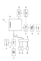
図1は、第1実施形態の分光撮像システム1の構成を示す図である。分光撮像システム1は、FD-OCTにより測定対象3の光断層像を取得するものであって、光源10、干渉器11、照射ユニット12、結合器21、単一波長光源22、分光撮像装置30、データ抽出部41、断層像データ生成部42、画像化部43、フォーカススコア算出部44および位置制御部45を備える。
FIG. 1 is a diagram illustrating a configuration of a
光源10は、広帯域の連続光を出力することができる。光源10として、例えば、SC光源,ASE光源およびSLD等が好適に用いられ得る。干渉器11は、マイケルソン型干渉計であり、光源10から出力された光を入力し該光を2分岐して測定光および参照光とし、測定光を照射ユニット12へ出力するとともに、照射ユニット12により測定対象3へ測定光が照射されることで測定対象3において生じた物体光を照射ユニット12から入力し、その物体光および参照光による干渉光を結合器21へ出力する。
The
単一波長光源22は、単一波長の単色光を出力する。この単色光の波長は、分光撮像装置30が検出することができる波長である。この単色光のスペクトルの半値全幅は、アレイ型受光部35の波長分解能(アレイ型受光部35の帯域幅を受光センサの個数で割った値)より小さい。結合器21は、干渉器11から出力される光、または、単一波長光源22から出力される単一波長の単色光を、分光撮像装置30に入力させる。結合器21および単一波長光源22は、分光撮像装置30に単一波長の単色光を入力させる単色光供給源を構成している。
The single
分光撮像装置30は、結合器21から到達した光のスペクトルを測定する。分光撮像装置30は、光ファイバ31,コリメートレンズ32,回折格子33,集光レンズ34およびアレイ型受光部35を備える。また、分光撮像装置30は、コリメートレンズ32,回折格子33,集光レンズ34およびアレイ型受光部35の間の相対的配置関係を調整する調整手段を備える。
The
光ファイバ31は、結合器21から出力された光を導いて、該光を端面から出力する。コリメートレンズ32は。光ファイバ31の端面から出力された光をコリメートする。回折格子33は、コリメートレンズ32によりコリメートされた光を入力して波長に応じて異なる方向へ光を出力する。集光レンズ34は、回折格子33から出力された光を波長に応じて異なる位置に集光する。アレイ型受光部35は、所定ラインに沿って一定ピッチでアレイ配置された複数の受光センサを有し、集光レンズ34により集光された光を受光する。
The
相対的配置関係を調整する調整手段は、コリメートレンズ32,回折格子33,集光レンズ34およびアレイ型受光部35それぞれを平行移動させる手段の他、これらの部品の方位を変更する手段を含む。特に、調整手段は、コリメートレンズ32の位置を調整する手段と、集光レンズ34とアレイ型受光部35との間の距離を調整する手段と、を含む。これらの調整手段として可動ステージ等が用いられる。
The adjusting means for adjusting the relative positional relationship includes means for changing the orientation of these components in addition to means for translating the
データ抽出部41は、アレイ型受光部35の複数の受光センサから出力されたラインデータ(各受光センサからの出力データの列)を受け取る。断層像データ生成部42は、このラインデータをフーリエ変換し、このフーリエ変換の結果に基づいて測定対象3の奥行き方向の1次元の光断層像を取得する。照射ユニット12は、測定対象3への測定光の照射を1次元または2次元に走査し、断層像データ生成部42は、その走査の際の各照射位置において測定対象3の奥行き方向の1次元の光断層像を取得する。そして、画像化部43は、断層像データ生成部42により取得された1次元の光断層像を積層することによって、測定対象3の2次元または3次元の光断層像を形成し表示する。
The
フォーカススコア算出部44は、アレイ型受光部35からデータ抽出部41が受け取ったラインデータに基づいて、分光撮像装置30における各光学部品の間の相対的配置関係の良好度合を表す評価値(フォーカススコア)を算出する。位置制御部45は、このフォーカススコアに基づいて、分光撮像装置30における各光学部品の間の相対的配置関係を調整する調整手段を制御する。
The focus
本実施形態では、フォーカススコアを求めて分光撮像装置30における各光学部品の間の相対的配置関係を調整するために、単一波長光源22から出力される単一波長の単色光を分光撮像装置30に入力させる。単一波長の単色光が分光撮像装置30に入力されたとき、アレイ型受光部35の受光面における光強度分布は、その波長に応じた位置でピークを有し、その位置から離れるほど強度が低下する。アレイ型受光部35の複数の受光センサそれぞれは、入射光強度に対して出力データが一定の線形関係にあるとする。
In the present embodiment, in order to obtain a focus score and adjust the relative positional relationship between the optical components in the
アレイ型受光部35から出力されるラインデータf(x)を下記(3)式のガウス関数で表す。aは、正の値であり、アレイ型受光部35の受光面における集光領域の大きさを表す。アレイ型受光部35から出力されるラインデータは、実際には位置xについて離散的であるが、ここでは位置xを変数とする関数として扱う。
The line data f (x) output from the array type
![]()
![]()
ラインデータf(x)の積分値(以下「単純和」という。)は下記(4a)式で表される。単純和の値は、a値に依らず一定値であり、集光領域の大きさに依らない。一方、ラインデータf(x)のα乗の積分値(以下「α乗和」という。)は下記(4b)式で表される。α>1であるとき、a値が大きいほど(集光領域が狭いほど)、α乗和の値は大きい。このことから、α乗和の値をフォーカススコアとして、この値が大きくなるように、分光撮像装置30における各光学部品の間の相対的配置関係を調整すればよい。
The integrated value (hereinafter referred to as “simple sum”) of the line data f (x) is expressed by the following equation (4a). The value of the simple sum is a constant value regardless of the a value, and does not depend on the size of the light collection region. On the other hand, the integral value of the α power of the line data f (x) (hereinafter referred to as “α power sum”) is expressed by the following equation (4b). When α> 1, the larger the a value (the narrower the light collection region), the larger the value of α sum. From this, the value of the sum of α powers is used as a focus score, and the relative arrangement relationship between the optical components in the
ただし、アレイ型受光部35から出力されるラインデータは実際には位置xについて離散的である。そこで、アレイ型受光部35のアレイ配置された複数の受光センサをP1〜PNとし、分光撮像装置30に単色光を入力させたときの各受光センサPnからの出力値をfnとして、下記(5)式の値をフォーカススコアとし、このフォーカススコアが最大となるように、分光撮像装置30における各光学部品の間の相対的配置関係を調整すればよい。
However, the line data output from the array type
![]()
![]()
分光撮像装置30における各光学部品の間の相対的配置関係を調整する際には、結合器21は、干渉器11からの光を分光撮像装置30に入力させず、単一波長光源22からの単色光を分光撮像装置30に入力させる。結合器21は、干渉器11から出力される光、および、単一波長光源22から出力される単色光のうち、何れか一方を選択して分光撮像装置30に入力させる光スイッチであってもよい。
When adjusting the relative positional relationship between the optical components in the
図2は、単一波長光源22から出力される単色光を分光撮像装置30に入力させたときのアレイ型受光部35から出力されるラインデータを示す図である。このラインデータは、単色光の波長に応じた位置でピークを有し、そのピーク位置から離れるほど値が低下する。分光撮像装置30における各光学部品の間の相対的配置関係が良好である場合Aでは、ラインデータのピークは高く、ピークの幅は狭い。一方、相対的配置関係が十分でない場合Bでは、ラインデータのピークは低く、ピークの幅は広い。
FIG. 2 is a diagram illustrating line data output from the array-type
図3は、分光撮像装置30における各光学部品の間の相対的配置関係とフォーカススコアとの関係を示す図である。横軸は、分光撮像装置30における各光学部品の間の相対的配置関係、すなわち、各光学部品の位置や方位を表す。分光撮像装置30における各光学部品の間の相対的配置関係が十分でない場合Bと比べて、相対的配置関係が良好である場合Aでは、フォーカススコアが大きい。分光撮像装置30における各光学部品の間の相対的配置関係の連続的な変化に対して、ラインデータの形状(ピーク高さ及び幅)も連続的に変化し、フォーカススコアも連続的に変化する。
FIG. 3 is a diagram illustrating the relationship between the relative arrangement relationship between the optical components and the focus score in the
したがって、分光撮像装置30における各光学部品の間の相対的配置関係を調整しながらフォーカススコアの変化を調べ、フォーカススコアが極大となる相対的配置関係を求めれば、最良の相対的配置関係を得ることができる。また、分光撮像装置30における各光学部品の間の相対的配置関係に周期的な変化を与え、このときに得られるフォーカススコアにおける同じ周期の変動成分を抽出して、その成分が最小となるように相対的配置関係を調整してもよい。
Therefore, if the change in the focus score is examined while adjusting the relative arrangement relationship between the optical components in the
図4〜図6は、第1実施形態の変形例の構成を示す図である。図1に示された構成と比較すると、図4〜図6に示される変形例では、分光撮像装置30に単一波長の単色光を入力させる単色光供給源の構成の点で相違する。
4-6 is a figure which shows the structure of the modification of 1st Embodiment. Compared with the configuration shown in FIG. 1, the modification shown in FIGS. 4 to 6 is different in the configuration of a monochromatic light supply source that inputs monochromatic light of a single wavelength to the
図4は、第1実施形態の変形例の分光撮像システム1Aの構成を示す図である。図1に示された構成と比較すると、図4に示される分光撮像システム1Aは、分光撮像装置30に単一波長の単色光を入力させる単色光供給源として結合器21および単一波長光源22を備える点では同じであるが、結合器21が光源10と干渉器11との間に設けられている点で相違する。分光撮像装置30における各光学部品の間の相対的配置関係を調整する際には、結合器21は、光源10からの光を干渉器11に入力させず、単一波長光源22からの単色光を干渉器11に入力させる。結合器21は、光源10から出力される光、および、単一波長光源22から出力される単色光のうち、何れか一方を選択して干渉器11に入力させる光スイッチであってもよい。この変形例では、光源10と単一波長光源22とを一つに纏めることができる。
FIG. 4 is a diagram illustrating a configuration of a spectral imaging system 1A according to a modification of the first embodiment. Compared with the configuration shown in FIG. 1, the
図5は、第1実施形態の変形例の分光撮像システム1Bの構成を示す図である。図1に示された構成と比較すると、図5に示される分光撮像システム1Bは、分光撮像装置30に単一波長の単色光を入力させる単色光供給源として、結合器21、分岐器23および単一波長透過フィルタ24を備える点で相違する。分岐器23は、光源10と干渉器11との間に設けられている。結合器21は、干渉器11と分光撮像装置30との間に設けられている。単一波長透過フィルタ24の透過帯域幅は、分光撮像装置30の波長分解能より狭い。分光撮像装置30における各光学部品の間の相対的配置関係を調整する際には、光源10から出力された光を分岐器23により単一波長透過フィルタ24に導入し、単一波長透過フィルタ24を透過した単一波長の単色光を結合器21により分光撮像装置30に入力させる。結合器21または分岐器23は光スイッチであってもよい。この変形例では、光源10とは別に、フォーカススコアを求める為の単一波長光源を設ける必要がない。
FIG. 5 is a diagram illustrating a configuration of a
図6は、第1実施形態の変形例の分光撮像システム1Cの構成を示す図である。図5に示された構成と比較すると、図6に示される分光撮像システム1Cは、分光撮像装置30に単一波長の単色光を入力させる単色光供給源として、結合器21、分岐器23および単一波長透過フィルタ24を備える点では同じであるが、結合器21および分岐器23の双方が光源10と干渉器11との間に設けられている点で相違する。結合器21または分岐器23は光スイッチであってもよい。この変形例でも、光源10とは別に、フォーカススコアを求める為の単一波長光源を設ける必要がない。
FIG. 6 is a diagram illustrating a configuration of a
(第2実施形態) (Second Embodiment)
図7は、第2実施形態の分光撮像システム2の構成を示す図である。分光撮像システム2は、FD-OCTにより測定対象の光断層像を取得するものであって、光源10、干渉器11、照射ユニット12、結合器21、合波器25、単一波長光源261〜26M、分光撮像装置30、データ抽出部41、断層像データ生成部42、画像化部43、フォーカススコア算出部44および位置制御部45を備える。
FIG. 7 is a diagram illustrating a configuration of the
図1に示された第1実施形態の構成と比較すると、図7に示される分光撮像システム2は、分光撮像装置30に単色光を入力させる単色光供給源として、結合器21、合波器25および複数の単一波長光源261〜26Mを備える点で相違する。
Compared with the configuration of the first embodiment shown in FIG. 1, the
各単一波長光源26mは、中心波長λmの単色光を出力する。波長λ1〜λMは、分光撮像装置30が検出することができる波長であり、互いに異なる。各単色光のスペクトルの半値全幅は、アレイ型受光部35の波長分解能より小さい。隣り合う2つの単色光の波長間隔の最小値は、アレイ型受光部35の波長分解能より大きい。隣り合う2つの単色光の波長間隔の最小値は、アレイ型受光部35の波長分解能の10倍以上であるのが好適であり、アレイ型受光部35が受光する光の波長帯域幅は、隣り合う2つの単色光の波長間隔の最大値の10倍以上であるのが好適である。
Each single
合波器25は、複数の単一波長光源261〜26Mから出力された波長λ1〜λMの単色光を合波して、その合波した光を結合器21へ出力する。結合器21は、干渉器11から出力される光、または、合波器25から出力される複数波長の単色光を、分光撮像装置30に入力させる。
本実施形態では、フォーカススコアを求めて分光撮像装置30における各光学部品の間の相対的配置関係を調整するために、複数の単一波長光源261〜26Mから出力された波長λ1〜λMの単色光を合波して分光撮像装置30に入力させる。複数波長の単色光が分光撮像装置30に入力されたとき、アレイ型受光部35の受光面における光強度分布は、各々波長に応じた位置でピークを有し、その位置から離れるほど強度が低下する。
In the present embodiment, in order to obtain the focus score and adjust the relative arrangement relationship between the optical components in the
複数の単一波長光源261〜26Mから出力される単色光の光量が一定であれば、第1実施形態と同様のフォーカススコアに基づいて、分光撮像装置30における各光学部品の間の相対的配置関係を調整することができる。複数の単一波長光源261〜26Mから出力される単色光の光量が一定でない場合、以下のようにして相対的配置関係を調整する。
If the amount of monochromatic light output from the plurality of single-
アレイ型受光部35から出力されるラインデータを下記(6)式のガウス関数fm(x)の和で表す。ガウス関数fm(x)は、単一波長光源26mから出力された波長λmの単色光のみが分光撮像装置30に入力されたときにアレイ型受光部35から出力されるラインデータを表す。Amは波長λmの単色光の光量を表し、amは波長λmの単色光の集光領域の大きさを表し、x0mは波長λmの単色光の集光領域におけるピーク位置を表す。
The line data output from the array type
![]()
![]()
単純和は下記(7a)式で表される。単純和の値は、am値に依らず一定値であり、集光領域の大きさに依らない。一方、α乗和は下記(7b)式で表される。α>1であるとき、am値が大きいほど(集光領域が狭いほど)、α乗和の値は大きい。しかし、α乗和の値は、光量Amが大きい波長λmの単色光の寄与が大きい。 The simple sum is expressed by the following equation (7a). The value of the simple sum is a constant value regardless of a m value, it does not depend on the size of the condensing region. On the other hand, the sum of α power is expressed by the following equation (7b). When a alpha> 1, as a m value is larger (higher condensing region is narrow), the value of alpha sum is large. However, the value of α sum is larger contribution of monochromatic light amount A m is greater wavelength lambda m.
そこで、本実施形態では、アレイ型受光部35の複数の受光センサP1〜PNのうち単色光λmの集光位置を含む連続範囲にある受光センサをグループGmが含むように複数の受光センサP1〜PNをM個のグループG1〜GMに分割する。各グループGmは、単色光λmの集光位置にある受光センサと、この受光センサの近傍にある受光センサと、を含む。そして、各グループGmにおける単純和のα乗の値とα乗和との比(下記(8)式)を求め、この比の総和(下記(9)式)をフォーカススコアとする。このフォーカススコアは、各単色光λmの光量Amに依存しない。このフォーカススコアが最大となるように、分光撮像装置30における各光学部品の間の相対的配置関係を調整すればよい。
Therefore, in this embodiment, the array type multiple light-receiving
ただし、アレイ型受光部35から出力されるラインデータは実際には位置xについて離散的である。そこで、アレイ型受光部35のアレイ配置された複数の受光センサをP1〜PNとし、分光撮像装置30に複数波長λ1〜λMの単色光を入力させたときの各受光センサPnからの出力値をfnとして、下記(10)式の値をフォーカススコアとし、このフォーカススコアが最大となるように、分光撮像装置30における各光学部品の間の相対的配置関係を調整すればよい。
However, the line data output from the array type
分光撮像装置30における各光学部品の間の相対的配置関係を調整する際には、結合器21は、干渉器11からの光を分光撮像装置30に入力させず、合波器25からの複数波長の単色光を分光撮像装置30に入力させる。結合器21は、干渉器11から出力される光、および、合波器25から出力される複数波長の単色光のうち、何れか一方を選択して分光撮像装置30に入力させる光スイッチであってもよい。
When adjusting the relative arrangement relationship between the optical components in the
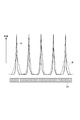
図8は、光量が等しい複数波長の単色光を分光撮像装置30に入力させたときのアレイ型受光部35から出力されるラインデータを示す図である。このラインデータは、単色光の各波長に応じた位置でピークを有し、そのピーク位置から離れるほど値が低下する。分光撮像装置30における各光学部品の間の相対的配置関係が良好である場合Aでは、ラインデータの全てのピークは高く、全てのピークの幅は狭い。一方、相対的配置関係が十分でない場合Bでは、ラインデータの何れかのピークは低く、何れかのピークの幅は広い。複数波長の単色光の光量が等しい場合、第1実施形態と同様のフォーカススコアに基づいて、分光撮像装置30における各光学部品の間の相対的配置関係を調整することができる。
FIG. 8 is a diagram illustrating line data output from the array-type
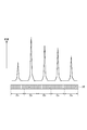
図9は、光量が異なる複数波長の単色光を分光撮像装置30に入力させたときのアレイ型受光部35から出力されるラインデータを示す図である。このような状態は、各波長の単色光の出力強度に差がある場合、または、経路の損失が波長によって異なる場合に起こり得る。このような状態の場合には、上記(10)式のフォーカススコアに基づいて、分光撮像装置30における各光学部品の間の相対的配置関係を調整することができる。
FIG. 9 is a diagram showing line data output from the array-type
図10〜図12は、第2実施形態の変形例の構成を示す図である。図7に示された構成と比較すると、図10〜図12に示される変形例では、分光撮像装置30に複数波長の単色光を入力させる単色光供給源の構成の点で相違する。
10-12 is a figure which shows the structure of the modification of 2nd Embodiment. Compared with the configuration shown in FIG. 7, the modification shown in FIGS. 10 to 12 is different in the configuration of a monochromatic light supply source that inputs monochromatic light having a plurality of wavelengths to the
図10は、第2実施形態の変形例の分光撮像システム2Aの構成を示す図である。図7に示された構成と比較すると、図10に示される分光撮像システム2Aは、分光撮像装置30に複数波長の単色光を入力させる単色光供給源として結合器21、合波器25および単一波長光源261〜26Mを備える点では同じであるが、結合器21が光源10と干渉器11との間に設けられている点で相違する。分光撮像装置30における各光学部品の間の相対的配置関係を調整する際には、結合器21は、光源10からの光を干渉器11に入力させず、合波器25からの複数波長の単色光を干渉器11に入力させる。結合器21は、光源10から出力される光、および、合波器25から出力される複数波長の単色光のうち、何れか一方を選択して干渉器11に入力させる光スイッチであってもよい。この変形例では、光源10と単一波長光源261〜26Mとを一つに纏めることができる。
FIG. 10 is a diagram illustrating a configuration of a
図11は、第2実施形態の変形例の分光撮像システム2Bの構成を示す図である。図7に示された構成と比較すると、図11に示される分光撮像システム2Bは、分光撮像装置30に複数波長の単色光を入力させる単色光供給源として、結合器21、分岐器23および複数波長透過フィルタ26を備える点で相違する。分岐器23は、光源10と干渉器11との間に設けられている。結合器21は、干渉器11と分光撮像装置30との間に設けられている。複数波長透過フィルタ26は、離散的な複数波長の光を透過させることができるもので、例えばエタロンフィルタである。複数波長透過フィルタ26の各々の透過帯域幅は、分光撮像装置30の波長分解能より狭い。分光撮像装置30における各光学部品の間の相対的配置関係を調整する際には、光源10から出力された光を分岐器23により複数波長透過フィルタ26に導入し、複数波長透過フィルタ26を透過した複数波長の単色光を結合器21により分光撮像装置30に入力させる。結合器21または分岐器23は光スイッチであってもよい。この変形例では、光源10とは別に、フォーカススコアを求める為の複数の単一波長光源を設ける必要がない。
FIG. 11 is a diagram illustrating a configuration of a
図12は、第2実施形態の変形例の分光撮像システム2Cの構成を示す図である。図11に示された構成と比較すると、図12に示される分光撮像システム2Cは、分光撮像装置30に複数波長の単色光を入力させる単色光供給源として、結合器21、分岐器23および複数波長透過フィルタ26を備える点では同じであるが、結合器21および分岐器23の双方が光源10と干渉器11との間に設けられている点で相違する。結合器21または分岐器23は光スイッチであってもよい。この変形例でも、光源10とは別に、フォーカススコアを求める為の単一波長光源を設ける必要がない。
FIG. 12 is a diagram illustrating a configuration of a
1,1A,1B,1C,2,2A,2B,2C…分光撮像システム、3…測定対象、10…光源、11…干渉器、12…照射ユニット、21…結合器、22…単一波長光源、23…分岐器、24…単一波長透過フィルタ、25…合波器、261〜26M…単一波長光源、27…複数波長透過フィルタ、30…分光撮像装置、31…光ファイバ、32…コリメートレンズ、33…回折格子、34…集光レンズ、35…アレイ型受光部、41…データ抽出部、42…断層像データ生成部、43…画像化部、44…フォーカススコア算出部、45…位置制御部。
1, 1A, 1B, 1C, 2, 2A, 2B, 2C ... Spectral imaging system, 3 ... Measurement object, 10 ... Light source, 11 ... Interferor, 12 ... Illumination unit, 21 ... Coupler, 22 ... Single wavelength light source , 23 ... branching device, 24 ... single wavelength transmission filter, 25 ... multiplexer, 26 1 to 26 M ... single wavelength light source, 27 ... multiple wavelength transmission filter, 30 ... spectral imaging device, 31 ... optical fiber, 32 DESCRIPTION OF SYMBOLS ... Collimating
Claims (7)
前記分光撮像装置に単色光を入力させたときに各受光センサPnからの出力値fnについて下記(1)式の値が最大となるように、前記コリメートレンズ,前記回折格子,前記集光レンズおよび前記アレイ型受光部の間の相対的配置関係を調整する、
ことを特徴とする分光撮像装置調整方法(ただし、nは1以上N以下の各整数)。
When the monochromatic light is input to the spectral imaging device, the collimating lens, the diffraction grating, and the condensing lens are set so that the value of the following equation (1) becomes maximum for the output value f n from each light receiving sensor P n. Adjusting the relative positional relationship between the lens and the array-type light receiving unit;
A spectral imaging apparatus adjustment method (where n is an integer from 1 to N).
各単色光のスペクトルの半値全幅が前記アレイ型受光部の波長分解能より小さく、隣り合う2つの単色光の波長間隔の最小値が前記波長分解能より大きい複数の単色光λ1〜λMを、前記分光撮像装置に入力させ、
前記複数の受光センサP1〜PNのうち単色光λmの集光位置を含む連続範囲にある受光センサをグループGmが含むように前記複数の受光センサP1〜PNをM個のグループG1〜GMに分割して、各受光センサPnからの出力値fnについて下記(2)式の値が最大となるように、前記コリメートレンズ,前記回折格子,前記集光レンズおよび前記アレイ型受光部の間の相対的配置関係を調整する、
ことを特徴とする分光撮像装置調整方法(ただし、nは1以上N以下の各整数、mは1以上M以下の各整数)。
A plurality of monochromatic lights λ 1 to λ M in which the full width at half maximum of the spectrum of each monochromatic light is smaller than the wavelength resolution of the array-type light receiving unit and the minimum wavelength interval between two adjacent monochromatic lights is larger than the wavelength resolution, Input to the spectral imaging device,
Said plurality of light receiving sensors P 1 to P N to include a group G m a light receiving sensor in a continuous range including a focusing position of the monochromatic light lambda m the M of the plurality of light receiving sensors P 1 to P N divided into groups G 1 ~G M, the output value f n from the respective light receiving sensors P n as the value of the following equation (2) is maximum, the collimating lens, the diffraction grating, the condenser lens and Adjusting the relative positional relationship between the array-type light receiving units;
A spectral imaging apparatus adjustment method (where n is an integer from 1 to N, and m is an integer from 1 to M).
前記アレイ型受光部が受光する光の波長帯域幅が隣り合う2つの単色光の波長間隔の最大値の10倍以上である、
ことを特徴とする請求項3に記載の分光撮像装置調整方法。 The minimum value of the wavelength interval between two adjacent monochromatic lights is 10 times or more of the wavelength resolution,
The wavelength bandwidth of the light received by the array-type light receiving unit is 10 times or more the maximum value of the wavelength interval between two adjacent monochromatic lights,
The method of adjusting a spectral imaging apparatus according to claim 3.
前記コリメートレンズによりコリメートされた光を入力して波長に応じて異なる方向へ光を出力する回折格子と、
前記回折格子から出力された光を波長に応じて異なる位置に集光する集光レンズと、
所定ラインに沿ってアレイ配置された複数の受光センサのうちの何れかの受光センサで前記集光レンズにより集光された光を受光するアレイ型受光部と、
前記コリメートレンズに入力される光の光路上に配置され、前記コリメートレンズに単色光を入力させる単色光供給源と、
前記コリメートレンズ,前記回折格子,前記集光レンズおよび前記アレイ型受光部の間の相対的配置関係を調整する調整手段と、
を備えることを特徴とする分光撮像システム。 A collimating lens that collimates the input light;
A diffraction grating for inputting the light collimated by the collimating lens and outputting the light in different directions according to the wavelength;
A condensing lens that condenses the light output from the diffraction grating at different positions according to the wavelength;
An array-type light receiving unit that receives light collected by the condensing lens by any one of the plurality of light receiving sensors arranged in an array along a predetermined line;
A monochromatic light supply source that is arranged on an optical path of light input to the collimating lens and that inputs monochromatic light to the collimating lens;
Adjusting means for adjusting a relative arrangement relationship between the collimating lens, the diffraction grating, the condenser lens, and the array-type light receiving unit;
A spectral imaging system comprising:
前記アレイ型受光部が受光する光の波長帯域幅が隣り合う2つの単色光の波長間隔の最大値の10倍以上である、
ことを特徴とする請求項5または6に記載の分光撮像システム。
The minimum value of the wavelength interval between two adjacent monochromatic lights is 10 times or more the wavelength resolution of the array type light receiving unit,
The wavelength bandwidth of the light received by the array-type light receiving unit is 10 times or more the maximum value of the wavelength interval between two adjacent monochromatic lights,
The spectral imaging system according to claim 5 or 6.
Priority Applications (5)
| Application Number | Priority Date | Filing Date | Title |
|---|---|---|---|
| JP2012150594A JP2014013185A (en) | 2012-07-04 | 2012-07-04 | Spectral imaging device adjustment method and spectral imaging system |
| EP13813547.0A EP2871451A1 (en) | 2012-07-04 | 2013-07-03 | Spectroscopic imaging device adjusting method and spectroscopic imaging system |
| CN201380035028.2A CN104718440A (en) | 2012-07-04 | 2013-07-03 | Spectroscopic imaging device adjusting method and spectroscopic imaging system |
| PCT/JP2013/068266 WO2014007291A1 (en) | 2012-07-04 | 2013-07-03 | Spectroscopic imaging device adjusting method and spectroscopic imaging system |
| US14/396,025 US20150077748A1 (en) | 2012-07-04 | 2013-07-03 | Spectroscopic imaging device adjusting method and spectroscopic imaging system |
Applications Claiming Priority (1)
| Application Number | Priority Date | Filing Date | Title |
|---|---|---|---|
| JP2012150594A JP2014013185A (en) | 2012-07-04 | 2012-07-04 | Spectral imaging device adjustment method and spectral imaging system |
Publications (1)
| Publication Number | Publication Date |
|---|---|
| JP2014013185A true JP2014013185A (en) | 2014-01-23 |
Family
ID=49882043
Family Applications (1)
| Application Number | Title | Priority Date | Filing Date |
|---|---|---|---|
| JP2012150594A Pending JP2014013185A (en) | 2012-07-04 | 2012-07-04 | Spectral imaging device adjustment method and spectral imaging system |
Country Status (5)
| Country | Link |
|---|---|
| US (1) | US20150077748A1 (en) |
| EP (1) | EP2871451A1 (en) |
| JP (1) | JP2014013185A (en) |
| CN (1) | CN104718440A (en) |
| WO (1) | WO2014007291A1 (en) |
Cited By (1)
| Publication number | Priority date | Publication date | Assignee | Title |
|---|---|---|---|---|
| JP2017083390A (en) * | 2015-10-30 | 2017-05-18 | エムテックスマツムラ株式会社 | Optical coherence tomography device |
Families Citing this family (2)
| Publication number | Priority date | Publication date | Assignee | Title |
|---|---|---|---|---|
| CN103900688A (en) * | 2014-03-28 | 2014-07-02 | 中国科学院上海技术物理研究所 | Imaging spectrometer beam splitting system based on free-form surface |
| CN108593104B (en) * | 2018-03-30 | 2020-06-26 | 北京化工大学 | Small-size high SNR hand-held type spectrum detecting system |
Family Cites Families (9)
| Publication number | Priority date | Publication date | Assignee | Title |
|---|---|---|---|---|
| JPS63295935A (en) * | 1987-05-28 | 1988-12-02 | Otsuka Denshi Kk | Spectrophotometry |
| JP2689707B2 (en) * | 1990-08-28 | 1997-12-10 | 松下電器産業株式会社 | Spectrometer with wavelength calibration function |
| CN1173548C (en) * | 1999-02-08 | 2004-10-27 | 深圳矽感科技有限公司 | Improved arrangement of light detector in colour image sensor |
| CN1811356A (en) * | 2006-02-20 | 2006-08-02 | 天津大学 | Spectral measuring method and instrument utilizing planar array photoelectric device |
| JP2007316007A (en) * | 2006-05-29 | 2007-12-06 | Yokogawa Electric Corp | Device and method for measuring light signal |
| JP2007327923A (en) * | 2006-06-09 | 2007-12-20 | Olympus Corp | Spectrometer and adjustment method of spectrometer |
| US7579601B2 (en) * | 2007-02-27 | 2009-08-25 | Metrosol, Inc. | Spectrometer with moveable detector element |
| CN101281061A (en) * | 2008-01-16 | 2008-10-08 | 蔡小舒 | High resolution spectral measuring apparatus |
| US8699024B2 (en) * | 2011-08-23 | 2014-04-15 | Jds Uniphase Corporation | Tunable optical filter and spectrometer |
-
2012
- 2012-07-04 JP JP2012150594A patent/JP2014013185A/en active Pending
-
2013
- 2013-07-03 US US14/396,025 patent/US20150077748A1/en not_active Abandoned
- 2013-07-03 CN CN201380035028.2A patent/CN104718440A/en active Pending
- 2013-07-03 EP EP13813547.0A patent/EP2871451A1/en not_active Withdrawn
- 2013-07-03 WO PCT/JP2013/068266 patent/WO2014007291A1/en active Application Filing
Cited By (1)
| Publication number | Priority date | Publication date | Assignee | Title |
|---|---|---|---|---|
| JP2017083390A (en) * | 2015-10-30 | 2017-05-18 | エムテックスマツムラ株式会社 | Optical coherence tomography device |
Also Published As
| Publication number | Publication date |
|---|---|
| EP2871451A1 (en) | 2015-05-13 |
| US20150077748A1 (en) | 2015-03-19 |
| CN104718440A (en) | 2015-06-17 |
| WO2014007291A1 (en) | 2014-01-09 |
Similar Documents
| Publication | Publication Date | Title |
|---|---|---|
| US20140362384A1 (en) | Spectroscopic instrument and process for spectral analysis | |
| US20130250290A1 (en) | Image mapped optical coherence tomography | |
| JP2008145188A (en) | Optical tomographic imaging apparatus | |
| JP2008086414A (en) | Optical tomographic imaging apparatus | |
| JP2007101262A (en) | Optical tomographic imaging device | |
| KR102341678B1 (en) | Optical characteristic measuring apparatus and optical characteristic measuring method | |
| JP5984693B2 (en) | Optical coherence tomography apparatus and optical coherence tomography method | |
| JP2009072280A (en) | Optical tomography imaging system, contact area detecting method, and image processing method using the same | |
| JP2009025245A (en) | Device for observing optical interference | |
| MX2013009423A (en) | Apparatus and method for optical coherence tomography. | |
| US20120105861A1 (en) | Device and method for determining optical path lengths | |
| JP2011237272A (en) | Optical distance meter and distance measuring method | |
| WO2014007291A1 (en) | Spectroscopic imaging device adjusting method and spectroscopic imaging system | |
| JP2005351839A (en) | Tomographic imaging equipment | |
| KR101078190B1 (en) | Wavelength detector and optical coherence topography having the same | |
| JP5891955B2 (en) | Timing generation apparatus for Fourier transform spectrometer and method, Fourier transform spectrometer and method | |
| JP2014115228A (en) | Interference measurement device and interference measurement method | |
| JP6378602B2 (en) | Optical measuring device | |
| WO2013015349A1 (en) | Optical tomographic image measuring apparatus and optical tomographic image measuring system | |
| JP4804977B2 (en) | Tunable laser device and optical tomographic imaging apparatus | |
| JP6303618B2 (en) | Photodetector and measuring device using the photodetector | |
| KR102498742B1 (en) | Multiple focusing-based high-resolution optical coherence tomography apparatus for depth-of-focus enhancement | |
| KR101709973B1 (en) | Measuring method using hybrid beam scanning optical coherence tomography and thereof | |
| KR20230135862A (en) | Multi-channel optical coherence tomography device based on michelson interferometer | |
| JP2006300664A (en) | Fourier spectral device and measuring timing detection method |