JP2014010077A - Testing device for insulation monitoring device, insulation monitoring device and testing method for insulation monitoring device - Google Patents
Testing device for insulation monitoring device, insulation monitoring device and testing method for insulation monitoring device Download PDFInfo
- Publication number
- JP2014010077A JP2014010077A JP2012147458A JP2012147458A JP2014010077A JP 2014010077 A JP2014010077 A JP 2014010077A JP 2012147458 A JP2012147458 A JP 2012147458A JP 2012147458 A JP2012147458 A JP 2012147458A JP 2014010077 A JP2014010077 A JP 2014010077A
- Authority
- JP
- Japan
- Prior art keywords
- phase
- current
- test
- insulation monitoring
- monitoring device
- Prior art date
- Legal status (The legal status is an assumption and is not a legal conclusion. Google has not performed a legal analysis and makes no representation as to the accuracy of the status listed.)
- Pending
Links
Images


Abstract
Description
本発明は、1線が接地された単相交流又は3相交流の監視対象の電路の零相電流を検出する零相電流検出センサと、前記零相電流から抽出した抵抗性の電流成分に基づいて、前記監視対象の電路が設定地絡発生状態に達したか否かを判断し、前記設定地絡発生状態に達したときに異常検出信号を出力する地絡検出部とが備えられた絶縁監視装置の動作試験を、前記零相電流検出センサの検出対象箇所に配置した試験用巻線に試験用電流を流して活線状態で行う絶縁監視装置用の試験装置、その試験装置を内蔵した絶縁監視装置、及び、絶縁監視装置の試験方法に関する。 The present invention is based on a zero-phase current detection sensor for detecting a zero-phase current in a circuit to be monitored of a single-phase AC or a three-phase AC with one wire grounded, and a resistive current component extracted from the zero-phase current. And a ground fault detector that determines whether the monitored electric circuit has reached a set ground fault occurrence state and outputs an abnormality detection signal when the set ground fault occurrence state is reached. Built-in test device for insulation monitoring device that performs operation test of monitoring device in a live state by supplying a test current to a test winding disposed at a detection target location of the zero-phase current detection sensor The present invention relates to an insulation monitoring device and a test method for the insulation monitoring device.
かかる試験装置の試験対象となる絶縁監視装置は、1線が接地された単相交流又は3相交流の電路の零相電流を検出し、その零相電流に基づいて地絡電流を検出する。
地絡電流は劣化した絶縁抵抗を介して流れる電流であるため、下記特許文献2に記載のように、その零相電流における電圧と同相の電流成分である抵抗性の電流成分を地絡電流として検出する。
このような構成の絶縁監視装置を動作試験するための試験装置としては、下記特許文献1に記載のように、監視対象の電路を停電させることなく活線状態のままで試験を行える装置構成が考えられている。
The insulation monitoring device to be tested by such a test device detects a zero-phase current in a single-phase AC or three-phase AC circuit in which one wire is grounded, and detects a ground fault current based on the zero-phase current.
Since the ground fault current is a current that flows through the deteriorated insulation resistance, a resistive current component that is a current component in phase with the voltage in the zero-phase current is used as the ground fault current as described in
As a test apparatus for performing an operation test on the insulation monitoring apparatus having such a configuration, as described in
電路を活線状態としたままで、すなわち、電路に地絡電流が流れている状態で、絶縁監視装置の試験を行おうとすると、元々電路に流れている地絡電流の取り扱いが問題となる。
下記特許文献1では、電路の零相電流を検出する零相電流検出センサの検出対象箇所に試験用巻線を配置して、元々電路に流れている地絡電流に足し合わせる状態で試験用電流を流し、その状態で絶縁監視装置の検出にかかる抵抗性の電流成分が所望の値となるように制御している。
When the insulation monitoring device is tested while the electric circuit is in a live line state, that is, in a state where a ground fault current is flowing in the electric circuit, handling of the ground fault current originally flowing in the electric circuit becomes a problem.
In the following
しかしながら、上記従来構成では、絶縁監視装置の一部を構成する零相電流検出センサの検出信号をそのまま流用して、試験用巻線に流す試験用電流を生成する構成では、零相電流検出センサの検出精度自体が劣化してしまったような場合では、元々の検出電流自体に誤差を含んでいるので、上記試験用電流にも誤差が含まれてしまう。
このような事態を回避するためには、上記特許文献1の別実施形態等にも記載のように、絶縁監視装置の零相電流検出センサの検出信号を流用するのではなく、十分な検出精度を有する零相電流検出センサを試験装置側で独自に備えて試験用電流を生成すれば良いが、その分だけ試験装置の装置コストが上昇してしまうと共に、高圧充電部(コンデンサ)等との接触事故を確実に回避しながら絶縁監視装置の試験のために別途零相電流検出センサを設置するのは、試験作業が煩雑なものとなってしまう。
本発明は、かかる実情に鑑みてなされたものであって、その目的は、絶縁監視装置に備えられる零相電流検出センサに零相電流が流れている状態下で、絶縁監視装置の動作状態を正確に把握できるようにする点にある。
However, in the above-described conventional configuration, the detection signal of the zero-phase current detection sensor that constitutes a part of the insulation monitoring device is used as it is to generate the test current that flows in the test winding. In the case where the detection accuracy itself is deteriorated, since the original detection current itself includes an error, the test current also includes an error.
In order to avoid such a situation, the detection signal of the zero-phase current detection sensor of the insulation monitoring device is not diverted as described in another embodiment of the above-mentioned
The present invention has been made in view of such circumstances, and its purpose is to change the operation state of the insulation monitoring device under a state in which the zero phase current is flowing through the zero phase current detection sensor provided in the insulation monitoring device. It is to be able to grasp accurately.
本出願の第1の発明は、1線が接地された単相交流又は3相交流の監視対象の電路の零相電流を検出する零相電流検出センサと、前記零相電流から抽出した抵抗性の電流成分に基づいて、前記監視対象の電路が設定地絡発生状態に達したか否かを判断し、前記設定地絡発生状態に達したときに異常検出信号を出力する地絡検出部とが備えられた絶縁監視装置の動作試験を、前記零相電流検出センサの検出対象箇所に配置した試験用巻線に試験用電流を流して活線状態で行う絶縁監視装置用の試験装置において、前記試験用電流を生成する試験用電流発生部と、前記試験用電流の電流値に基づいて、前記絶縁監視装置の前記地絡検出部が前記異常検出信号を出力する状態となる電流値を演算する動作電流演算部とが備えられ、前記試験用電流発生部は、前記抵抗性の電流成分の位相を特定すると共に、前記試験用電流として、前記抵抗性の電流成分と同相の成分を含む同相試験用電流と、前記抵抗性の電流成分と逆相の成分を含む逆相試験用電流とを生成可能で、且つ、前記同相試験用電流における前記抵抗性の電流成分と同相の成分及び前記逆相試験用電流における前記抵抗性の電流成分と逆相の成分の電流値を変更操作可能に構成され、前記動作電流演算部は、経時的に前記同相の成分の電流値が変更操作される前記同相試験用電流を流している状態で、前記絶縁監視装置の前記地絡検出部が前記異常検出信号を出力する状態となるときの前記同相試験用電流における前記同相の成分の電流値I1と対応する値を電流値記憶手段に記憶保持すると共に、経時的に前記逆相の成分の電流値が変更操作される前記逆相試験用電流を流している状態で、前記絶縁監視装置の前記地絡検出部が前記異常検出信号を出力する状態となるときの前記逆相試験用電流における前記逆相の成分の電流値I2と対応する値を電流値記憶手段に記憶保持し、前記絶縁監視装置の前記地絡検出部が前記異常検出信号を出力する状態となる電流値Iを、I=(I1+I2)/2として演算するように構成されている。 The first invention of the present application is a zero-phase current detection sensor for detecting a zero-phase current of a circuit to be monitored of a single-phase AC or a three-phase AC with one wire grounded, and a resistance extracted from the zero-phase current. A ground fault detection unit that determines whether or not the monitoring target electric circuit has reached a set ground fault occurrence state based on the current component, and outputs an abnormality detection signal when the set ground fault occurrence state is reached; In the test apparatus for the insulation monitoring device, the operation test of the insulation monitoring device provided with is performed in a live state by supplying a test current to the test winding disposed in the detection target portion of the zero-phase current detection sensor. Based on the current value of the test current generating unit for generating the test current and the current for the test, the ground fault detection unit of the insulation monitoring device calculates a current value at which the abnormality detection signal is output. And an operating current calculation unit that performs the test current generation. The phase of the resistive current component is specified, and as the test current, a common-mode test current including a component in phase with the resistive current component, and a phase of the resistive current component and the opposite phase A negative-phase test current including a component, and a component in phase with the resistive current component in the common-mode test current and a component in reverse phase with the resistive current component in the negative-phase test current. The insulation monitoring device is configured to be capable of changing the current value of the component, and the operating current calculation unit is in a state where the current for common mode test in which the current value of the component of the common phase is changed over time is flowing. stores held in the current value storage means and corresponding values the current value I 1 of the components of the in-phase in the in-phase test current when the ground fault detection portion of the state for outputting the abnormality detection signal, time Of the reverse phase component In the reverse phase test current when the ground fault detection unit of the insulation monitoring device is in a state of outputting the abnormality detection signal in the state where the reverse phase test current whose flow value is changed is flowing. stores and holds a value corresponding to the current value I 2 components of the opposite phase to the current value storage means, a current value I the ground fault detection portion is a state for outputting the abnormality detection signal of the insulation monitoring device, The calculation is performed as I = (I 1 + I 2 ) / 2.
すなわち、抵抗性の電流成分と同相(同じ位相)の成分を含む上記同相試験用電流を試験用巻線に流して、絶縁監視装置の零相電流検出センサに検出させ、絶縁監視装置の地絡検出部が異常検出信号を出力する状態となるとき(異常検出信号を出力しない状態から異常検出信号を出力する状態に切り替わるとき)の上記同相試験用電流における抵抗性の電流成分と同相の成分の電流値I1を特定できる値を記憶保持すると共に、抵抗性の電流成分と逆相(位相差が180度)の成分を含む上記逆相試験用電流を試験用巻線に流して、絶縁監視装置の零相電流検出センサに検出させ、絶縁監視装置の地絡検出部が異常検出信号を出力する状態となるとき(異常検出信号を出力しない状態から異常検出信号を出力する状態に切り替わるとき)の上記逆相試験用電流における抵抗性の電流成分と逆相の成分の電流値I2を特定できる値を記憶保持する。尚、上記同相試験用電流を流しての測定と上記逆相試験用電流を流しての測定とは、測定順序の先後はどちらでも良い。
絶縁監視装置の地絡検出部が異常検出信号を出力する状態となる電流値Iは、I=(I1+I2)/2として求まる。
電流値I1及び電流値I2は、何れも、試験装置側で特定できる値であるので、絶縁監視装置の地絡検出部が異常検出信号を出力する状態となる電流値Iを、絶縁監視装置の零相電流検出センサの検出精度に依存せずに、試験装置側で取得した値によって求めることができる。
That is, the above-mentioned common-mode test current including a component having the same phase (same phase) as the resistive current component is caused to flow through the test winding so that the zero-phase current detection sensor of the insulation monitoring device detects the ground fault. When the detector enters a state where an abnormality detection signal is output (when switching from a state where no abnormality detection signal is output to a state where an abnormality detection signal is output), the resistance current component and the in-phase component of the common-mode test current A value that can identify the current value I 1 is stored and retained, and the above-described negative phase test current including a component having a phase opposite to the resistive current component (phase difference is 180 degrees) is supplied to the test winding to monitor insulation. When the zero-phase current detection sensor of the device detects it and the ground fault detection unit of the insulation monitoring device enters the state of outputting the abnormality detection signal (when switching from the state of not outputting the abnormality detection signal to the state of outputting the abnormality detection signal) upon The values that can identify a current value I 2 of the components of resistive current component opposite phase in Kigyakusho test current stores and holds. The measurement with the common-mode test current and the measurement with the reverse-phase test current applied may be performed either before or after the measurement order.
The current value I at which the ground fault detection unit of the insulation monitoring device outputs an abnormality detection signal is obtained as I = (I 1 + I 2 ) / 2.
Since both the current value I 1 and the current value I 2 are values that can be specified on the test device side, the current value I that causes the ground fault detection unit of the insulation monitoring device to output an abnormality detection signal is measured as insulation monitoring. It can be obtained from the value acquired on the test apparatus side without depending on the detection accuracy of the zero-phase current detection sensor of the apparatus.
以下において、このようにして求まる理由を説明する。
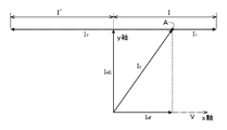
先ず、単相交流の場合について説明する。
単相交流を複素平面上においてベクトル表示で示す図5に示すように、x軸に電圧位相すなわち抵抗性の電流成分の位相をとって、零相電流検出センサが検出する零相電流をI0とすると、零相電流I0は、抵抗性の電流成分I0rと容量性の電流成分I0cとに分解できる。この容量性の電流成分I0cは、電圧位相(x軸)よりも90度位相が進んだものとして規定できる。
説明を簡単にするために、上記同相試験用電流が抵抗性の電流成分と同相の成分のみからなるものとし、又、上記逆相試験用電流も抵抗性の電流成分と逆相の成分のみからなるものとする。
Hereinafter, the reason why it is obtained in this way will be described.
First, the case of single-phase alternating current will be described.
As shown in FIG. 5 in which single-phase alternating current is represented by a vector on the complex plane, the zero-phase current detected by the zero-phase current detection sensor is expressed as I 0 by taking the voltage phase, that is, the phase of the resistive current component on the x-axis. Then, the zero-phase current I 0 can be decomposed into a resistive current component I 0 r and a capacitive current component I 0 c. This capacitive current component I 0 c can be defined as a phase advanced 90 degrees from the voltage phase (x-axis).
In order to simplify the explanation, it is assumed that the current for in-phase testing is composed only of a component having the same phase as the resistive current component, and the current for testing of the reverse phase is also composed only of components having the opposite phase from the resistive current component. Shall be.
監視対象の電路が活線状態であり、上記の零相電流I0が流れている状態で、上記同相試験用電流を試験用巻線に流す。
上記同相試験用電流の電流値(厳密には、上記同相試験用電流における抵抗性の電流成分と同相の成分の電流値)を変更操作して、絶縁監視装置の地絡検出部が上記異常検出信号を出力していない状態から出力する状態に切り替わる電流値を特定する。この電流値を図5に示すように「I1」とする。図5では、「I1」を、点A(「I0」の終点)を始点としてベクトル表示している。
ここで、電流値I1は、試験装置側から供給する電流であるので、その値を正確に特定できる。
従って、絶縁監視装置の地絡検出部は、図5から、I=I0r+I1で表される抵抗性の電流成分と同相の電流値「I」で上記異常検出信号を出力する状態となったことになる。この「I」は、絶縁監視装置において計測した値ではなく、実際の電流値である。
The current for in-phase test is supplied to the test winding while the electric circuit to be monitored is in a live line state and the zero-phase current I 0 is flowing.
The ground fault detection unit of the insulation monitoring device detects the abnormality by changing the current value of the common mode test current (strictly speaking, the current value of the resistive current component and the common phase component in the common mode test current). The current value at which the signal is not output is switched to the output state. This current value is “I 1 ” as shown in FIG. In FIG. 5, “I 1 ” is displayed as a vector with the point A (the end point of “I 0 ”) as the starting point.
Here, the current value I 1 is because it is the current supplied from the testing apparatus can accurately identify the value.
Therefore, the ground fault detection unit of the insulation monitoring device is in a state of outputting the abnormality detection signal with the current value “I” in phase with the resistive current component represented by I = I 0 r + I 1 from FIG. That's right. This “I” is not a value measured by the insulation monitoring device but an actual current value.
更に、上記逆相試験用電流の電流値(厳密には、上記逆相試験用電流における抵抗性の電流成分と逆相の成分の電流値)を変更操作して、絶縁監視装置の地絡検出部が上記異常検出信号を出力していない状態から出力する状態に切り替わる電流値を特定する。この電流値を図5に示すように「I2」とする。図5では、「I2」を、点A(「I0」の終点)を始点としてベクトル表示している。
電流値I2は、試験装置側から供給する電流であるので、その値を正確に特定できる。
従って、絶縁監視装置の地絡検出部は、図5から、I’=I2−I0rで表される抵抗性の電流成分と逆相の電流値「I’」で上記異常検出信号を出力する状態となったことになる。この「I’」も、絶縁監視装置において計測した値ではなく、実際の電流値である。
I=I’と見なせるので、図5から明らかなように、I=(I1+I2)/2として求まる。
これを数式で表すと、I+I’=I1+I2で、I=I’と見なして、I=(I1+I2)/2となる。
絶縁監視装置は、通常、抵抗性の電流成分と逆相の成分の電流値「I’」に対しても、抵抗性の電流成分と同相の成分の電流値「I」の場合と同様に検出動作するように設計されているので、上述のようにして「I」を求めるに際して、絶縁監視装置の改造等は特に必要ない。
Further, the current value of the current for the reverse phase test (strictly speaking, the current value of the resistive current component and the reverse phase component in the current for the reverse phase test) is changed to detect the ground fault of the insulation monitoring device. A current value that switches from a state in which the unit does not output the abnormality detection signal to a state in which the abnormality detection signal is output is specified. This current value is assumed to be “I 2 ” as shown in FIG. In FIG. 5, “I 2 ” is displayed as a vector with the point A (the end point of “I 0 ”) as the starting point.
Current value I 2 is because it is the current supplied from the testing apparatus can accurately identify the value.
Therefore, the ground fault detection unit of the insulation monitoring device outputs the abnormality detection signal with a current value “I ′” having a phase opposite to that of the resistive current component represented by I ′ = I 2 −I 0 r from FIG. It is in a state to output. This “I ′” is not a value measured by the insulation monitoring device but an actual current value.
Since it can be considered that I = I ′, as is apparent from FIG. 5, it is obtained as I = (I 1 + I 2 ) / 2.
When this is expressed by a mathematical expression, I + I ′ = I 1 + I 2 and I = I ′, and I = (I 1 + I 2 ) / 2.
The insulation monitoring device normally detects the current value “I ′” of the component having the opposite phase to the resistive current component in the same manner as the case of the current value “I” of the component having the same phase as the resistive current component. Since it is designed to operate, it is not particularly necessary to modify the insulation monitoring device when obtaining “I” as described above.
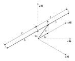
次に3相交流の場合について説明する。位相関係が若干複雑になるが、基本的な考え方は上述の単相交流の場合と全く同様である。
3相交流の場合について、図5と同様にベクトル表示したものを図6に示す。
図6では、3相をa相,b相,c相として、b相を接地したときのa相及びc相の電圧ベクトルを示している。a相及びc相の電圧ベクトルは、b相を基準とした(b相を原点とした)対地電圧として表示している。
図6の3相交流の場合、絶縁監視装置は、図6においてx軸の位相で抵抗性の電流成分を検出している。
図6のx軸は、a相の電圧ベクトルとc相の電圧ベクトルとの間の中央の位相としており、このため、地絡がa相で発生しても、あるいは、c相で発生しても、両者を区別することなく検出できる。x軸とa相,c相との位相差はいずれも30度であるので、x軸での検出結果を2/sqrt(3)(sqrt( )は、平方根を求める関数とする)倍することで、a相あるいはc相での抵抗性の電流成分(地絡電流)として求まる。
Next, the case of three-phase alternating current will be described. Although the phase relationship is slightly complicated, the basic idea is exactly the same as in the case of the single-phase AC described above.
FIG. 6 shows a vector display similar to FIG. 5 in the case of three-phase alternating current.
FIG. 6 shows the a-phase and c-phase voltage vectors when the three phases are a-phase, b-phase, and c-phase, and the b-phase is grounded. The voltage vectors of the a phase and the c phase are displayed as ground voltages with the b phase as a reference (b phase as the origin).
In the case of the three-phase alternating current in FIG. 6, the insulation monitoring device detects a resistive current component with the x-axis phase in FIG.
The x-axis in FIG. 6 is a central phase between the a-phase voltage vector and the c-phase voltage vector. Therefore, even if a ground fault occurs in the a-phase or in the c-phase, Can also be detected without distinguishing between the two. Since the phase difference between the x-axis and the a-phase and c-phase is 30 degrees, the detection result on the x-axis is multiplied by 2 / sqrt (3) (where sqrt () is a function for obtaining the square root). Thus, it is obtained as a resistive current component (ground fault current) in the a phase or the c phase.
図6において、零相電流検出センサが検出する零相電流をI0とすると、a相の電圧位相に対応させて試験用電流を流すことを想定して、零相電流I0は、a相での抵抗性の電流成分I0rと容量性の電流成分I0cとに分解できる。この容量性の電流成分I0cはa相の容量性の電流成分とc相の容量性の電流成分とのベクトル和である。両者の位相はy軸を挟んで両側に30度の位相差を有し、又、両者の値は等しい物と見なして実用上差し支えないので、両者を足し合わせた容量性の電流成分I0cはx軸よりも90度位相が進んだy軸に平行なベクトルとして規定できる。
説明を簡単にするために、上記同相試験用電流が抵抗性の電流成分と同相の成分のみからなるものとし、又、上記逆相試験用電流も抵抗性の電流成分と逆相の成分のみからなるものとする。
In FIG. 6, assuming that the zero-phase current detected by the zero-phase current detection sensor is I 0 , the zero-phase current I 0 is represented by the a-phase assuming that a test current is caused to flow corresponding to the voltage phase of the a-phase. Can be broken down into a resistive current component I 0 r and a capacitive current component I 0 c. The capacitive current component I 0 c is a vector sum of the a-phase capacitive current component and the c-phase capacitive current component. Both phases have a phase difference of 30 degrees on both sides of the y-axis, and since both values are regarded as being equal to each other, there is no problem in practical use. Therefore, a capacitive current component I 0 c obtained by adding the two together. Can be defined as a vector parallel to the y-axis that is 90 degrees ahead of the x-axis.
In order to simplify the explanation, it is assumed that the current for in-phase testing is composed only of a component having the same phase as the resistive current component, and the current for testing of the reverse phase is also composed only of components having the opposite phase from the resistive current component. Shall be.
監視対象の電路が活線状態であり、上記の零相電流I0が流れている状態で、a相の電圧位相と同相の上記同相試験用電流を試験用巻線に流す。
上記同相試験用電流の電流値(厳密には、上記同相試験用電流における抵抗性の電流成分と同相の成分の電流値)を変更操作して、絶縁監視装置の地絡検出部が上記異常検出信号を出力していない状態から出力する状態に切り替わる電流値を特定する。この電流値を図6に示すように「I1」とする。図6では、「I1」を、点A(「I0」の終点)を始点としてベクトル表示している。
電流値I1は、試験装置側から供給する電流であるので、その値を正確に特定できる。
従って、絶縁監視装置の地絡検出部は、図6から、I=I0r+I1で表される抵抗性の電流成分と同相の電流値「I」で上記異常検出信号を出力する状態となったことになる。この「I」は、絶縁監視装置において計測した値ではなく、実際の電流値である。
When the monitored electric circuit is in a live line state and the zero-phase current I 0 is flowing, the common-mode test current having the same phase as the voltage phase of the a-phase is supplied to the test winding.
The ground fault detection unit of the insulation monitoring device detects the abnormality by changing the current value of the common mode test current (strictly speaking, the current value of the resistive current component and the common phase component in the common mode test current). The current value at which the signal is not output is switched to the output state. This current value is assumed to be “I 1 ” as shown in FIG. In FIG. 6, “I 1 ” is displayed as a vector starting from point A (end point of “I 0 ”).
Current value I 1 is because it is the current supplied from the testing apparatus can accurately identify the value.
Accordingly, the ground fault detection unit of the insulation monitoring device is in a state of outputting the abnormality detection signal with a current value “I” in phase with the resistive current component represented by I = I 0 r + I 1 from FIG. That's right. This “I” is not a value measured by the insulation monitoring device but an actual current value.
更に、上記逆相試験用電流の電流値(厳密には、上記逆相試験用電流における抵抗性の電流成分と逆相の成分の電流値)を変更操作して、絶縁監視装置の地絡検出部が上記異常検出信号を出力していない状態から出力する状態に切り替わる電流値を特定する。この電流値を図6に示すように「I2」とする。図6では、「I2」を、点A(「I0」の終点)を始点としてベクトル表示している。
電流値I2は、試験装置側から供給する電流であるので、その値を正確に特定できる。
従って、絶縁監視装置の地絡検出部は、図6から、I’=I2−I0rで表される抵抗性の電流成分と逆相の電流値「I’」で上記異常検出信号を出力する状態となったことになる。この「I’」も、絶縁監視装置において計測した値ではなく、実際の電流値である。
I=I’と見なせるので、図6から明らかなように、I=(I1+I2)/2として求まる。
これを数式で表すと、I+I’=I1+I2で、I=I’と見なして、I=(I1+I2)/2となる。
Further, the current value of the current for the reverse phase test (strictly speaking, the current value of the resistive current component and the reverse phase component in the current for the reverse phase test) is changed to detect the ground fault of the insulation monitoring device. A current value that switches from a state in which the unit does not output the abnormality detection signal to a state in which the abnormality detection signal is output is specified. This current value is set to “I 2 ” as shown in FIG. In FIG. 6, “I 2 ” is displayed as a vector with the point A (the end point of “I 0 ”) as the starting point.
Current value I 2 is because it is the current supplied from the testing apparatus can accurately identify the value.
Therefore, the ground fault detection unit of the insulation monitoring apparatus outputs the abnormality detection signal with a current value “I ′” having a phase opposite to that of the resistive current component represented by I ′ = I 2 −I 0 r from FIG. It is in a state to output. This “I ′” is not a value measured by the insulation monitoring device but an actual current value.
Since it can be considered that I = I ′, it is obtained as I = (I 1 + I 2 ) / 2 as apparent from FIG.
When this is expressed by a mathematical expression, I + I ′ = I 1 + I 2 and I = I ′, and I = (I 1 + I 2 ) / 2.
c相の電圧位相に対応させて試験用電流を流す場合は、図7に示す位相関係となり、図6のa相の電圧位相に対応させる場合と同様の関係となるので、詳細な説明を省略する。図7においても、図6と同様に、a相及びc相の電圧ベクトルは、b相を基準とした(b相を原点とした)対地電圧として表示している。
以上のように、単相の場合でも、あるいは、3相の場合でも、I=(I1+I2)/2の関係で、試験装置側での測定値によって、絶縁監視装置の地絡検出部が異常検出信号を出力したときの電流値を正確に特定することができる。
When the test current is caused to flow corresponding to the c-phase voltage phase, the phase relationship shown in FIG. 7 is obtained, and the same relationship as that corresponding to the a-phase voltage phase shown in FIG. To do. Also in FIG. 7, as in FIG. 6, the voltage vectors of the a phase and the c phase are displayed as ground voltages with the b phase as a reference (b phase as the origin).
As described above, even in the case of a single phase or a case of three phases, the ground fault detection unit of the insulation monitoring device is determined by the measured value on the test device side in the relationship of I = (I 1 + I 2 ) / 2. The current value when the abnormality detection signal is output can be accurately specified.
又、本出願の第2の発明は、上記第1の発明の構成に加えて、前記監視対象の電路における非接地相の電圧位相である第2電圧位相と、装置動作用電力を受電する電路の電圧位相である第1電圧位相とを測定すると共に、前記第2電圧位相と前記第1電圧位相との位相差に対応する位相差データを位相差記憶手段に記憶保持する位相差計測部が備えられ、前記試験用電流発生部は、前記第1電圧位相の測定値と前記位相差記憶手段に記憶されている位相差データとに基づいて、前記同相試験用電流及び前記逆相試験用電流の位相を設定するように構成されている。 In addition to the configuration of the first invention, the second invention of the present application includes a second voltage phase that is a voltage phase of a non-grounded phase in the monitoring target electric circuit, and an electric circuit that receives power for operating the apparatus. A phase difference measurement unit that measures a first voltage phase that is a voltage phase of the second voltage phase and stores phase difference data corresponding to a phase difference between the second voltage phase and the first voltage phase in a phase difference storage unit; And the test current generator is configured to generate the in-phase test current and the reverse-phase test current based on the measured value of the first voltage phase and the phase difference data stored in the phase difference storage means. Is configured to set the phase.
すなわち、上記同相試験用電流及び上記逆相試験用電流の位相の設定については、これらの試験用電流を流す度に、対象とする電圧位相を計測することによっても可能ではあるが、それでは絶縁監視装置の試験作業を煩雑化させてしまうことになる。
一方、試験装置は、装置動作用電力の受電のためにコンセント等を経て電路に接続されることが一般的であり、受電する電路の電圧位相と監視対象の電路の電圧位相とは一定の位相差を有することが知られている。
そこで、試験装置が受電する電路の電圧位相と監視対象の電路の電圧位相との位相差に対応する位相差データを予め取得しておき、試験装置にて絶縁監視装置の試験を行う際には、試験装置が受電する電路の電圧位相と上記位相差データとから、試験用電流(同相試験用電流及び逆相試験用電流)の位相を設定する。
In other words, the phase of the in-phase test current and the reverse-phase test current can be set by measuring the voltage phase of interest each time these test currents are supplied. This complicates the test operation of the apparatus.
On the other hand, the test apparatus is generally connected to an electric circuit through an outlet or the like for receiving the electric power for operating the apparatus, and the voltage phase of the electric circuit to be received and the voltage phase of the electric circuit to be monitored are constant. It is known to have a phase difference.
Therefore, when the phase difference data corresponding to the phase difference between the voltage phase of the electric circuit received by the test apparatus and the voltage phase of the electric circuit to be monitored is acquired in advance, and the insulation monitoring apparatus is tested by the test apparatus The phase of the test current (in-phase test current and reverse-phase test current) is set from the voltage phase of the electric circuit that the test apparatus receives and the phase difference data.
又、本出願の第3の発明は、上記第1の発明の構成に加えて、前記絶縁監視装置に、前記抵抗性の電流成分の位相と前記絶縁監視装置が装置動作用電力を受電する電路の電圧位相との位相差に対応する位相差データが記憶保持され、前記試験用電流発生部は、前記絶縁監視装置に記憶保持されている前記位相差データを入力する入力部が備えられて、前記入力部から入力された前記位相差データと、装置動作用電力を受電する電路の電圧位相の測定値とに基づいて、前記同相試験用電流及び前記逆相試験用電流の位相を設定するように構成されている。 According to a third invention of the present application, in addition to the configuration of the first invention, the insulation monitoring device has a phase of the resistive current component and an electric circuit through which the insulation monitoring device receives device operating power. The phase difference data corresponding to the phase difference from the voltage phase is stored and held, and the test current generator is provided with an input unit for inputting the phase difference data stored and held in the insulation monitoring device, Based on the phase difference data input from the input unit and the measured value of the voltage phase of the electric circuit that receives the device operating power, the phase of the in-phase test current and the reverse-phase test current is set. It is configured.
すなわち、絶縁監視装置は、零相電流の測定データから抵抗性の電流成分を抽出する機能を有しているので、監視対象の電路の抵抗性の電流成分の位相の特定が必要となる。
絶縁監視装置における上記抵抗性の電流成分の位相の特定手法としては、絶縁監視装置が装置動作用電力の受電のために接続されている電路における電圧位相と、監視対象の電路の電圧位相とが一定の位相差を有することを利用して、上記抵抗性の電流成分の位相と絶縁監視装置が受電する電路の電圧の位相との位相差に対応する位相差データを予め取得しておき、絶縁監視装置が受電する電路の電圧位相の測定結果と上記位相差データとから、上記抵抗性の電流成分の位相を特定する構成とする場合が多い。
That is, since the insulation monitoring device has a function of extracting a resistive current component from the measurement data of the zero-phase current, it is necessary to specify the phase of the resistive current component of the monitored electric circuit.
As a method for specifying the phase of the resistive current component in the insulation monitoring device, the voltage phase in the electric circuit to which the insulation monitoring device is connected for receiving the power for operating the device and the voltage phase of the electric circuit to be monitored are By utilizing the fact that the phase difference is constant, phase difference data corresponding to the phase difference between the phase of the resistive current component and the phase of the voltage of the electrical circuit received by the insulation monitoring device is acquired in advance. In many cases, the configuration is such that the phase of the resistive current component is specified from the measurement result of the voltage phase of the electric circuit received by the monitoring device and the phase difference data.
試験装置は、絶縁監視装置が装置動作用電力を受電している電路と同じ電路か、あるいは、その電路と一定の位相差となる電路に接続されて装置動作用電力を受電することになるが、絶縁監視装置に上述のような機能が備えられている場合、絶縁監視装置が保持している上記位相差データを利用できる。
そこで、絶縁監視装置に上記位相差データを出力できる機能を備えると共に、試験装置の入力部にその位相差データを入力し、その位相差データと、試験装置が装置動作用電力を受電する電路の電圧位相の測定値とに基づいて、試験用電流(同相試験用電流及び逆相試験用電流)の位相を設定する。
The test device receives power for operating the device by being connected to the same circuit as the circuit that the insulation monitoring device is receiving power for operating the device, or to a circuit having a certain phase difference from the circuit. When the insulation monitoring device has the above-described function, the phase difference data held by the insulation monitoring device can be used.
Therefore, the insulation monitoring device is provided with a function capable of outputting the phase difference data, and the phase difference data is input to the input unit of the test device, and the phase difference data and the circuit for receiving the device operating power by the test device are received. Based on the measured value of the voltage phase, the phase of the test current (in-phase test current and reverse-phase test current) is set.
又、本出願の第4の発明は、上記第1〜第3のいずれかの発明の構成に加えて、前記試験用電流発生部は、前記同相試験用電流における前記抵抗性の電流成分と同相の成分及び前記逆相試験用電流における前記抵抗性の電流成分と逆相の成分の電流値を漸増させるように構成されている。
すなわち、上記同相試験用電流あるいは上記逆相試験用電流を流して絶縁監視装置の地絡検出部が異常検出信号を出力する状態となる電流値を求めるについては、その電流値の推定値を挟んで試験用電流値を変化させると共に、その変化幅を徐々に小さくすることで、絶縁監視装置の地絡検出部が異常検出信号を出力する状態となる電流値を特定する手法も考えられるが、上記同相試験用電流及び上記逆相試験用電流を漸増させて、絶縁監視装置の地絡検出部が上記異常検出信号を出力する状態となる電流値を特定することで、上記同相試験用電流及び上記逆相試験用電流の制御態様を簡略化することができる。
According to a fourth invention of the present application, in addition to the configuration of any one of the first to third inventions, the test current generator is in phase with the resistive current component in the common mode test current. And the current value of the resistive current component and the negative phase component in the negative phase test current are gradually increased.
That is, when obtaining the current value at which the ground fault detection unit of the insulation monitoring device outputs an abnormality detection signal by flowing the in-phase test current or the reverse phase test current, the estimated value of the current value is sandwiched. In addition to changing the test current value, and gradually reducing the change width, a method of identifying the current value at which the ground fault detection unit of the insulation monitoring device outputs an abnormality detection signal is also considered, By gradually increasing the common-mode test current and the reverse-phase test current, the ground fault detection unit of the insulation monitoring device specifies the current value at which the abnormality detection signal is output. The control mode of the reverse phase test current can be simplified.
又、本出願の第5の発明は、上記第1〜第4の発明の構成に加えて、前記零相電流検出センサは、前記電路の接地線を検出対象箇所として設置されている。
すなわち、監視対象の電路の零相電流を検出する上記零相電流検出センサの設置箇所としては、電路の接地線以外にも設置可能であるが、電路の接地線に上記零相電流検出センサを設置することで、設置作業を簡単に行える。
According to a fifth invention of the present application, in addition to the configurations of the first to fourth inventions, the zero-phase current detection sensor is installed with a ground line of the electric circuit as a detection target location.
That is, the zero-phase current detection sensor for detecting the zero-phase current in the circuit to be monitored can be installed in place other than the ground line of the circuit, but the zero-phase current detection sensor is installed on the ground line of the circuit. By installing, installation work can be performed easily.
又、本出願の第6の発明は、上記第1〜第5のいずれかの発明の構成を備えた絶縁監視装置用の試験装置を内蔵して絶縁監視装置が構成されている。
すなわち、絶縁監視装置と、その絶縁監視装置を試験する試験装置とは、両者で共通の処理を行う部分も少なくない。
従って、上記試験装置を絶縁監視装置に内蔵してしまうことで、絶縁監視装置としての機能と試験装置としての機能とで、処理要素を共用させることが可能となる。
According to a sixth aspect of the present application, an insulation monitoring apparatus is constructed by incorporating a test apparatus for an insulation monitoring apparatus having the structure of any one of the first to fifth aspects of the invention.
In other words, the insulation monitoring device and the test device for testing the insulation monitoring device often have a common process.
Therefore, by incorporating the test apparatus in the insulation monitoring apparatus, it is possible to share the processing element between the function as the insulation monitoring apparatus and the function as the test apparatus.
又、本出願の第7の発明は、上記第6の発明の構成に加えて、装置動作用電力を受電する電路の電圧を計測する電圧計測部と、前記監視対象の電路における非接地相の電圧位相である第2電圧位相と装置動作用電力を受電する電路の電圧位相である第1電圧位相とを測定すると共に、前記第2電圧位相と前記第1電圧位相との位相差に対応する位相差データを位相差記憶手段に記憶保持する位相差計測部とが備えられ、前記地絡検出部は、前記電圧計測部の計測情報と前記位相差計測部の前記位相差記憶手段の記憶情報とに基づいて前記抵抗性の電流成分を抽出するように構成され、前記試験装置の前記試験用電流発生部は、前記電圧計測部の計測情報と前記位相差計測部の前記位相差記憶手段の記憶情報とに基づいて前記同相試験用電流及び前記逆相試験用電流の位相を設定するように構成されている。 According to a seventh aspect of the present application, in addition to the configuration of the sixth aspect, a voltage measuring unit that measures a voltage of a circuit that receives power for operating the apparatus, and a non-grounded phase in the monitored circuit. Measures a second voltage phase that is a voltage phase and a first voltage phase that is a voltage phase of a circuit that receives power for operating the apparatus, and corresponds to a phase difference between the second voltage phase and the first voltage phase A phase difference measurement unit that stores and holds phase difference data in a phase difference storage unit, and the ground fault detection unit includes measurement information of the voltage measurement unit and storage information of the phase difference storage unit of the phase difference measurement unit. The resistive current component is extracted based on the test current generation unit of the test apparatus, the test current generation unit of the test device, the measurement information of the voltage measurement unit and the phase difference storage unit of the phase difference measurement unit And the current for common mode testing based on the stored information. It is configured to set a phase of the reverse-phase test current.
すなわち、絶縁監視装置と、その絶縁監視装置を試験する試験装置とは、電圧等の位相に着目して各種の処理を行う点で共通している。
従って、上記試験装置を絶縁監視装置に内蔵してしまうことで、上記の位相情報を取得するために必要となる上記電圧計測部及び上記位相差計測部を、両者で兼用することができる。
That is, the insulation monitoring device and the test device that tests the insulation monitoring device are common in that various processes are performed by paying attention to the phase of voltage or the like.
Therefore, by incorporating the test device in the insulation monitoring device, the voltage measurement unit and the phase difference measurement unit necessary for obtaining the phase information can be used by both.
又、本出願の第8の発明は、1線が接地された単相交流又は3相交流の監視対象の電路の零相電流を検出する零相電流検出センサと、前記零相電流から抽出した抵抗性の電流成分に基づいて、前記監視対象の電路が設定地絡発生状態に達したか否かを判断し、前記設定地絡発生状態に達したときに異常検出信号を出力する地絡検出部とが備えられた絶縁監視装置の動作試験を、前記零相電流検出センサの検出対象箇所に配置した試験用巻線に試験用電流を流して活線状態で行う絶縁監視装置の試験方法において、前記零相電流検出センサの検出対象箇所に試験用巻線を配置し、前記抵抗性の電流成分の位相を特定し、前記試験用巻線に前記抵抗性の電流成分と同相の成分を含む同相試験用電流を流して、その同相の成分の電流値を変更操作し、前記絶縁監視装置の前記地絡検出部が前記異常検出信号を出力する状態となるときの前記同相試験用電流における前記同相の成分の電流値I1と対応する値を取得すると共に、前記試験用巻線に前記抵抗性の電流成分と逆相の成分を含む逆相試験用電流を流して、その逆相の成分の電流値を変更操作し、前記絶縁監視装置の前記地絡検出部が前記異常検出信号を出力する状態となるときの前記逆相試験用電流における前記逆相の成分の電流値I2と対応する値を取得し、前記絶縁監視装置の前記地絡検出部が前記異常検出信号を出力する状態となる電流値Iを、I=(I1+I2)/2として演算する。 The eighth invention of the present application is a zero-phase current detection sensor that detects a zero-phase current in a circuit to be monitored for single-phase AC or three-phase AC with one wire grounded, and extracted from the zero-phase current. Based on the resistance current component, it is determined whether or not the monitored electric circuit has reached the set ground fault occurrence state, and an abnormality detection signal is output when the set ground fault occurrence state is reached. In the test method of the insulation monitoring device, the operation test of the insulation monitoring device provided with a section is performed in a live line state by supplying a test current to a test winding disposed at a detection target location of the zero-phase current detection sensor. The test winding is arranged at the detection target location of the zero-phase current detection sensor, the phase of the resistive current component is specified, and the test winding includes a component in phase with the resistive current component An in-phase test current is applied to change the current value of the in-phase component. Wherein with said ground fault detection portion of the insulation monitoring apparatus acquires the current value I 1 and the corresponding values of the components of the in-phase in the in-phase test current when the state of outputting the abnormality detection signal, for the test A current for a negative phase test including a component having a phase opposite to that of the resistive current component is caused to flow through the winding, and a current value of the component having a negative phase is changed, and the ground fault detection unit of the insulation monitoring device is Gets the corresponding values to the current value I 2 components of the reverse phase in the reversed phase test current when the state of outputting an abnormality detection signal, wherein the ground fault detector is the abnormality detection of the insulation monitoring device A current value I at which a signal is output is calculated as I = (I 1 + I 2 ) / 2.
すなわち、抵抗性の電流成分と同相の成分を含む上記同相試験用電流を試験用巻線に流して、絶縁監視装置の零相電流検出センサに検出させ、絶縁監視装置の地絡検出部が異常検出信号を出力する状態となるとき(異常検出信号を出力しない状態から異常検出信号を出力する状態に切り替わるとき)の上記同相試験用電流における抵抗性の電流成分と同相の成分の電流値I1を特定できる値を記憶保持すると共に、抵抗性の電流成分と逆相(位相差が180度)の成分を含む上記逆相試験用電流を試験用巻線に流して、絶縁監視装置の零相電流検出センサに検出させ、絶縁監視装置の地絡検出部が異常検出信号を出力する状態となるとき(異常検出信号を出力しない状態から異常検出信号を出力する状態に切り替わるとき)の上記逆相試験用電流における抵抗性の電流成分と逆相の成分の電流値I2を特定できる値を記憶保持する。尚、上記同相試験用電流を流しての測定と上記逆相試験用電流を流しての測定とは、測定順序の先後はどちらでも良い。
絶縁監視装置の地絡検出部が異常検出信号を出力する状態となる電流値Iは、I=(I1+I2)/2として求まる。
電流値I1及び電流値I2は、何れも、試験装置側で特定できる値であるので、絶縁監視装置の地絡検出部が異常検出信号を出力する状態となる電流値Iを、絶縁監視装置の零相電流検出センサの検出精度に依存せずに、試験装置側で取得した値によって求めることができる。
このようにして、上記「I」を求めることができる理由は上述の通りである。
That is, the above-mentioned common-mode test current including a component having the same phase as the resistive current component is caused to flow through the test winding and detected by the zero-phase current detection sensor of the insulation monitoring device, and the ground fault detection unit of the insulation monitoring device is abnormal. When the detection signal is output (when switching from the state where no abnormality detection signal is output to the state where an abnormality detection signal is output), the current value I 1 of the component having the same phase as the resistive current component in the common-mode test current Is stored and held, and the above-described negative phase test current including a component having a phase opposite to the resistive current component (phase difference is 180 degrees) is caused to flow through the test winding, so that the zero phase of the insulation monitoring device When the current detection sensor detects the ground fault detection unit of the insulation monitoring device enters a state where an abnormality detection signal is output (when switching from a state where no abnormality detection signal is output to a state where an abnormality detection signal is output) For testing The values that can identify a current value I 2 of the components of resistive current component opposite phase in current store holding. The measurement with the common-mode test current and the measurement with the reverse-phase test current applied may be performed either before or after the measurement order.
The current value I at which the ground fault detection unit of the insulation monitoring device outputs an abnormality detection signal is obtained as I = (I 1 + I 2 ) / 2.
Since both the current value I 1 and the current value I 2 are values that can be specified on the test device side, the current value I that causes the ground fault detection unit of the insulation monitoring device to output an abnormality detection signal is measured as insulation monitoring. It can be obtained from the value acquired on the test apparatus side without depending on the detection accuracy of the zero-phase current detection sensor of the apparatus.
The reason why “I” can be obtained in this way is as described above.
上記第1の発明によれば、試験装置側で特定できる電流値によって絶縁監視装置の地絡検出部が異常検出信号を出力する状態となる電流値Iを求めることができるので、絶縁監視装置に備えられる零相電流検出センサに零相電流が流れている状態下で、絶縁監視装置の動作状態を正確に把握できるものとなった。
又、上記第2の発明によれば、試験装置が装置動作用電力を受電する電路の電圧位相と監視対象の電路の電圧位相との位相差に対応する位相差データを予め取得しておき、試験装置にて絶縁監視装置の試験を行う際には、試験装置が装置動作用電力を受電する電路の電圧位相と上記位相差データとから、試験用電流(同相試験用電流及び逆相試験用電流)の位相を設定することで、試験用電流の位相の設定を簡便に行うことができる。
According to the first aspect of the invention, since the current value I at which the ground fault detection unit of the insulation monitoring device outputs an abnormality detection signal can be obtained from the current value that can be specified on the test device side, Under the condition that the zero-phase current is flowing through the zero-phase current detection sensor provided, the operation state of the insulation monitoring device can be accurately grasped.
Further, according to the second invention, the phase difference data corresponding to the phase difference between the voltage phase of the circuit where the test apparatus receives power for operating the apparatus and the voltage phase of the monitored circuit is acquired in advance. When testing the insulation monitoring device with the test equipment, the test equipment uses the voltage phase of the circuit that receives the power for operating the equipment and the above phase difference data to obtain the test current (for in-phase test current and reverse-phase test use). By setting the phase of (current), it is possible to easily set the phase of the test current.
又、上記第3の発明によれば、絶縁監視装置が保持するデータを利用して試験用電流(同相試験用電流及び逆相試験用電流)の位相を設定することで、試験用電流の位相の設定を簡便に行うことができる。
又、上記第4の発明によれば、上記同相試験用電流及び上記逆相試験用電流を漸増させて、絶縁監視装置が上記異常検出信号を出力する状態となる電流値を特定することで、上記同相試験用電流及び上記逆相試験用電流の制御態様を簡略化することができる。
又、上記第5の発明によれば、上記零相電流検出センサの設置作業を簡単に行えるので、絶縁監視装置の設置作業負担を軽減できる。
According to the third aspect of the invention, the phase of the test current is set by setting the phase of the test current (the current for the in-phase test and the current for the reverse phase test) using the data held by the insulation monitoring device. Can be easily set.
According to the fourth invention, by gradually increasing the in-phase test current and the reverse-phase test current, the current value at which the insulation monitoring device outputs the abnormality detection signal is specified. The control mode of the in-phase test current and the reverse-phase test current can be simplified.
Further, according to the fifth aspect, the installation work of the zero-phase current detection sensor can be easily performed, so that the installation work load of the insulation monitoring device can be reduced.
又、上記第6の発明によれば、上記試験装置を絶縁監視装置に内蔵してしまうことで、絶縁監視装置としての機能と試験装置としての機能とで、処理要素を共用させることが可能となり、システム全体の装置構成を簡素化することができる。
又、上記第7の発明によれば、上記試験装置を絶縁監視装置に内蔵してしまうことで、絶縁監視装置としての機能と試験装置としての機能とで、上記電圧計測部と上記位相差計測部とを共用させることが可能となり、システム全体の装置構成を簡素化することができる。
又、上記第8の発明によれば、試験装置側で特定できる電流値によって絶縁監視装置が異常検出信号を出力する状態となる電流値Iを求めることができるので、絶縁監視装置に備えられる零相電流検出センサに零相電流が流れている状態下で、絶縁監視装置の動作状態を正確に把握できるものとなった。
Further, according to the sixth aspect, by incorporating the test device in the insulation monitoring device, it becomes possible to share the processing elements for the function as the insulation monitoring device and the function as the test device. The apparatus configuration of the entire system can be simplified.
According to the seventh aspect of the present invention, since the test device is built in the insulation monitoring device, the voltage measurement unit and the phase difference measurement can be performed with the function as the insulation monitoring device and the function as the test device. Can be shared with each other, and the system configuration of the entire system can be simplified.
According to the eighth aspect of the invention, the current value I at which the insulation monitoring device outputs an abnormality detection signal can be obtained from the current value that can be specified on the test device side. Under the condition that the zero-phase current is flowing through the phase current detection sensor, the operation state of the insulation monitoring device can be accurately grasped.
以下、本発明の絶縁監視装置用の試験装置の実施の形態を図面に基づいて説明する。
<第1実施形態>
〔全体構成〕
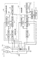
電力需要家の電源受配電設備付近での機器の接続形態を概略的に示す図1のように、配電線から引込み線Lにて電源受配電設備に引込まれた6.6kVの高圧は、変圧器T1にて単相3線の低電圧交流に変圧され、変圧器T2にて200Vの3相3線の低電圧交流に変圧される。変圧器T1は、いわゆる電灯変圧器と称されるものであり、変圧器T2は、いわゆる動力変圧器と称されるものである。
変圧器T1,T2の2次側(低圧側)の一端はB種接地線にて接地され、単相3線については中性点が接地され、3相3線については3相の線のうちの1相の線が接地されている。
本第1実施形態では、上記のうち、動力変圧器T2の3相3線側の電路を監視対象とするように設置された絶縁監視装置IOを例示して、その絶縁監視装置IOの動作試験を試験装置ITにて行う場合を説明する。
絶縁監視装置IOは、監視対象の電路の零相電流を検出して監視動作を行っており、絶縁監視装置IOの一部でもある零相電流検出センサZCTにて、3相3線側の電路の零相電流を検出している。
零相電流検出センサZCTは零相変流器1にて構成され、動力変圧器T2側の接地線EBに取り付けられている。
Embodiments of a test apparatus for an insulation monitoring apparatus according to the present invention will be described below with reference to the drawings.
<First Embodiment>
〔overall structure〕
The high voltage of 6.6 kV drawn into the power receiving / distributing facility from the distribution line by the lead-in line L as shown in FIG. 1 schematically showing the connection form of the equipment near the power receiving / distributing facility of the electric power consumer The transformer T1 is transformed into a single-phase three-wire low-voltage alternating current, and the transformer T2 is transformed into a 200-V three-phase three-wire low-voltage alternating current. The transformer T1 is a so-called electric transformer, and the transformer T2 is a so-called power transformer.
One end of the secondary side (low voltage side) of the transformers T1 and T2 is grounded by a B-type ground wire, the neutral point is grounded for a single-phase three-wire, and the three-phase three-wire is a three-phase wire The one-phase wire is grounded.
In the first embodiment, among the above, the insulation monitoring device IO installed so as to monitor the electric circuit on the three-phase three-wire side of the power transformer T2 is exemplified, and the operation test of the insulation monitoring device IO is performed. A case where the test apparatus IT performs the above will be described.
The insulation monitoring device IO performs a monitoring operation by detecting the zero-phase current of the monitoring target electric circuit. The zero-phase current detection sensor ZCT, which is also a part of the insulation monitoring device IO, performs a three-phase three-wire side electric circuit. The zero-phase current is detected.
The zero-phase current detection sensor ZCT is composed of a zero-phase
〔絶縁監視装置IOの構成〕
絶縁監視装置IOには、零相変流器1の検出情報と抵抗性の電流成分の位相の特定情報とに基づいて、監視対象の電路が設定地絡発生状態に達したか否かを判断し、設定地絡発生状態に達したときに異常検出信号を出力する地絡検出部EFと、地絡検出部EFが出力する異常検出信号を受け取って、警報音あるいは警報ランプ等によって警報を出力する警報出力部2とが備えられている。
本第1実施形態では,上記零相電流に含まれる抵抗性の電流成分の電流値が設定判別値(例えば、50mA)以上となった状態を上記設定地絡発生状態とし、その設定判別値に達したときに上記異常検出信号を出力するものとして説明するが、上記設定地絡状態に達したか否かは、例えば地絡抵抗値等の上記零相電流に含まれる抵抗性の電流成分の電流値と対応する各種のパラメータの値にて規定できる。
[Configuration of insulation monitoring device IO]
The insulation monitoring device IO determines whether or not the monitored electric circuit has reached the set ground fault occurrence state based on the detection information of the zero-phase
In the first embodiment, a state in which the current value of the resistive current component included in the zero-phase current is equal to or greater than a set determination value (for example, 50 mA) is set as the set ground fault occurrence state, and the set determination value is It will be described that the abnormality detection signal is output when it reaches, but whether or not the set ground fault state is reached is determined by, for example, a resistance current component included in the zero-phase current such as a ground fault resistance value. It can be defined by the values of various parameters corresponding to the current value.
地絡検出部EFには、零相変流器1が検出した零相電流を計測し、適切な信号レベルに変換して出力する電流計測部3と、絶縁監視装置IOが装置動作用電力を受電する電路の電圧を計測し、適切な信号レベルに変換して出力する電圧計測部4と、監視対象の電路における非接地相の電圧位相(上記第2電圧位相)と装置動作用電力を受電する電路の電圧位相(上記第1電圧位相)とを測定すると共に、その第2電圧位相と第1電圧位相との位相差に対応する位相差データを位相差記憶手段であるメモリ5aに記憶保持する位相差計測部5と、電流計測部3,電圧計測部4及び位相差計測部5の出力信号に基づいて地絡成分(上記零相電流に含まれる抵抗性の電流成分)を抽出し、その抽出した値が上記設定判別値に達したときに上記異常検出信号を出力する地絡成分抽出部6とが備えられている。
The ground fault detector EF measures the zero-phase current detected by the zero-phase
絶縁監視装置IOは、電灯系変圧器T1の2次側の電路からAC100Vのコンセント等を経て装置動作用電力を受電しており、図1に示すように、その受電した電圧が地絡検出部EFの電圧計測部4に入力されている。
位相差計測部5は、電圧計測部4から受け取った信号で、装置動作用電力を受電する電路の電圧位相(上記第1電圧位相)を、その電圧変化におけるゼロクロス点検出等によって測定すると共に、監視対象の電路における非接地相(例えば、図6におけるa相)に接続して、その電圧変化におけるゼロクロス点検出等によってその電圧位相(上記第2電圧位相)を測定する。
The insulation monitoring device IO receives power for operating the device from the secondary side of the electric light transformer T1 via an AC 100V outlet, etc., and the received voltage is the ground fault detector as shown in FIG. The voltage is input to the
The phase
メモリ5aに記憶保持する位相差データは、図6を用いて説明した抵抗性の電流成分の検出形態を考慮して、取得した第2電圧位相(ここでは、a相の電圧位相とする)と第1電圧位相との位相差に若干の変更を加えた位相差とする。
すなわち、地絡成分抽出部6における抵抗性の電流成分検出のための位相は、a相とc相との成分を一体に検出するために、a相とc相との位相差の1/2をa相の位相に加えた位相(換言すると、a相の位相から30度進んだ位相)を検出位相としているので、その位相差も考慮して上記位相差データを生成する。
従って、上記第2電圧位相と上記第1電圧位相との単純な位相差ではなく、上記第2電圧位相から30度進んだ位相と上記第1電圧位相との位相差を上記位相差データとする変更を加えてメモリ5aに記憶保持する。
もちろん、上記第2電圧位相として、a相及びc相の両方の電圧位相を測定し、それらの平均値の位相と上記第1電圧位相との位相差を上記位相差データとしてメモリ5aに記憶保持するようにしても良い。
上記第2電圧位相と上記第1電圧位相との位相差は、電路の結線状態等(図1では、変圧器T1,T2の結線状態)によって決まるものであり、変化することはない。従って、絶縁監視装置IOの設置時に、1度だけ、上記位相の測定処理を行って、上記位相差データをメモリ5aに記憶保持させれば良く、その後は、位相差計測部5と監視対象の電路における非接地相(a相)との配線接続も不必要で、取り外しても良い。
The phase difference data stored and held in the
That is, the phase for detecting the resistive current component in the ground fault
Therefore, not the simple phase difference between the second voltage phase and the first voltage phase, but the phase difference between the phase advanced by 30 degrees from the second voltage phase and the first voltage phase is used as the phase difference data. Changes are made and stored in the
Of course, both the a-phase and c-phase voltage phases are measured as the second voltage phase, and the phase difference between the average phase and the first voltage phase is stored in the
The phase difference between the second voltage phase and the first voltage phase is determined by the connection state of the electric circuit and the like (in FIG. 1, the connection state of the transformers T1 and T2) and does not change. Accordingly, when the insulation monitoring device IO is installed, the phase measurement process is performed only once and the phase difference data is stored in the
尚、取得した第2電圧位相と第1電圧位相との位相差をそのまま上記位相差データとして、メモリ5aに記憶保持するようにしても良く、この場合は、その位相差データを利用する地絡成分抽出部6側で上述の30度の位相差を調整すれば良い。
このように、メモリ5aに記憶保持する位相差データは、上記第2電圧位相と上記第1電圧位相との位相差と対応する位相差データ、すなわち、上記第2電圧位相と上記第1電圧位相との位相差を特定できる位相差データであれば足りる。
Note that the acquired phase difference between the second voltage phase and the first voltage phase may be stored in the
Thus, the phase difference data stored in the
地絡成分抽出部6は、監視対象の電路の絶縁監視動作において、電圧計測部4から受け取る電圧信号、すなわち、装置動作用電力を受電している電灯変圧器T1の二次側の電路の電圧信号の位相を測定し、その測定結果の位相にメモリ5aに記憶保持されている位相差データを加算(又は、減算)することで、図6におけるx軸の位相(抵抗性の電流成分の位相として把握できる位相)を特定する。
電流計測部3の検出信号から、上記x軸の位相の電流成分を抽出し、それを2/sqrt(3)(sqrt( )は、平方根を求める関数とする)倍することで、a相での抵抗性の電流成分とc相での抵抗性の電流成分とを足し合わせた地絡電流として検出できる。
すなわち、a相で地絡が発生しても、あるいは、c相で地絡が発生しても、両者を区別無く検出できる。
この検出した地絡電流が、上記設定判別値に達したときに上記異常検出信号を出力するのは上述の通りである。
絶縁監視装置IOを構成する位相差計測部5及び地絡成分抽出部6の処理は、CPUあるいはDSP等を備えてソフトウェア処理にて実現できるが、アナログ乗算回路等のハードウェア構成をも含む回路構成としても良い。
The ground fault
The current component of the x-axis phase is extracted from the detection signal of the
That is, even if a ground fault occurs in the a phase or a ground fault occurs in the c phase, both can be detected without distinction.
As described above, when the detected ground fault current reaches the setting determination value, the abnormality detection signal is output.
The processing of the phase
〔試験装置ITの構成〕
試験装置ITには、試験装置ITが装置動作用電力を受電する電路の電圧を計測し、適切な信号レベルに変換して出力する電圧計測部11と、絶縁監視装置IOの監視対象の電路における非接地相の電圧位相(上記第2電圧位相)と装置動作用電力を受電する電路の電圧位相(上記第1電圧位相)とを測定すると共に、その第2電圧位相と第1電圧位相との位相差に対応する位相差データを位相差記憶手段であるメモリ12aに記憶保持する位相差計測部12と、電圧計測部11及び位相差計測部12の出力信号に基づいて試験用電流を生成する試験用電流発生部13と、試験用電流発生部13が生成している試験用電流の電流値を受け取って、絶縁監視装置IOの動作電流を演算する動作電流演算部14と、試験装置ITによる絶縁監視装置IOの試験動作を制御する試験制御部15と、試験制御部15に対して絶縁監視装置IOに対する試験動作の開始を指示する試験開始指示入力部16とが備えられている。
図1に示すように、絶縁監視装置IOの動作試験のために、零相変流器1の検出対象箇所に試験用巻線TLを配置しており、試験用電流発生部13で生成した試験用電流を試験用巻線TLに流し、それを零相変流器1にて検出させることで、絶縁監視装置IOの動作試験を行う。
又、試験装置ITも、絶縁監視装置IOと同様に、電灯系変圧器T1の2次側の電路からAC100Vのコンセント等を経て装置動作用電力を受電しており、上記第1電圧位相も、試験装置ITと絶縁監視装置IOとで共通である。
[Configuration of test equipment IT]
The test apparatus IT includes a
As shown in FIG. 1, for the operation test of the insulation monitoring device IO, a test winding TL is arranged at a detection target location of the zero-phase
Further, the test apparatus IT also receives power for operating the apparatus from the secondary side of the electric light transformer T1 through an AC 100V outlet, etc., as in the insulation monitoring apparatus IO, and the first voltage phase is The test apparatus IT and the insulation monitoring apparatus IO are common.
試験装置ITの電圧計測部11は、絶縁監視装置IOの電圧計測部4と全く同一の構成であり、試験装置ITの位相差計測部12は、絶縁監視装置IOの位相差計測部5と共通の機能を有するが、メモリ12aに記憶保持させる位相差データが若干異なる。
すなわち、絶縁監視装置IOでは、メモリ5aに記憶保持させる位相差データは、地絡成分抽出部6が抽出する位相が図6のx軸に相当する位相であることから、上記第2電圧位相から30度進んだ位相と上記第1電圧位相との位相差であるのに対して、試験装置ITでは、図6におけるa相の電圧位相を基準に試験用電流を生成するため、上記第2電圧位相と上記第1電圧位相との位相差をメモリ12aに位相差データとして記憶保持させている。この点以外では、絶縁監視装置IOの位相差計測部5と試験装置ITの位相差計測部12とは同一構成である。従って、絶縁監視装置IOの位相差計測部5の場合と同様に、試験装置ITの設置時に、1度だけ、上記位相の測定処理を行って、上記位相差データをメモリ12aに記憶保持させれば良く、その後は、位相差計測部12と監視対象の電路における非接地相(a相)との配線接続も不必要で、取り外しても良い。
The
That is, in the insulation monitoring device IO, the phase difference data stored in the
試験用電流発生部13は、例えばI/V変換回路で電流出力段を構成すれば良く、試験用電流の元となる正弦波電圧信号は、電圧計測部11から受け取った電圧信号を波形整形して使用しても良いし、正弦波波形データをD/A変換して生成しても良い。
試験用電流発生部13は、上記試験用電流として、図6におけるa相の電圧位相と同相(同一の位相)の同相試験用電流(図6において「I1」で示す試験用電流)と、図6におけるa相の電圧位相と逆相(位相差が180度)の逆相試験用電流(図6において「I2」で示す試験用電流)とを生成する。
上記同相試験用電流は、電圧計測部11から受け取る電圧信号、すなわち、装置動作用電力を受電している電灯変圧器T1の二次側の電路の電圧信号の位相を測定し、その測定結果の位相にメモリ12aに記憶保持されている位相差データを加算(又は、減算)して抵抗性の電流成分の位相を特定し、その位相となるように、上記の正弦波電圧信号の位相を設定することで生成する。
又、上記逆相試験用電流は、上記同相試験用電流の生成の際の正弦波電圧信号に対して、例えば正負反転させる等の処理によって位相を更に180度シフトさせることで生成する。
The test
The test
The in-phase test current is obtained by measuring the phase of the voltage signal received from the
Further, the reverse phase test current is generated by further shifting the phase by 180 degrees, for example, by reversing the polarity of the sine wave voltage signal at the time of generating the in-phase test current.
試験用電流発生部13は、上記の正弦波電圧信号の振幅を変化させることで、上記同相試験用電流及び上記逆相試験用電流の電流値を経時的に変更操作可能としている。
上記同相試験用電流及び上記逆相試験用電流の電流値の経時的な変更操作の態様としては、試験用電流発生部13は、試験制御部15から上記同相試験用電流及び上記逆相試験用電流のうちのいずれかの通電を指示されたときに、そのいずれかの試験用電流の電流値を漸増させる。
The test
As an aspect of the change operation over time of the current values of the common-mode test current and the reverse-phase test current, the test-
上記同相試験用電流及び上記逆相試験用電流については、夫々、抵抗性の電流成分(すなわち、a相又はc相の電圧位相の成分)及び抵抗性の電流成分と逆相の成分を含むものであれば良いが、夫々、上述のような抵抗性の電流成分及び抵抗性の電流成分と逆相の電流成分のみによって構成することで、試験用電流の取り扱いを簡素化することができる。
このように設定している関係で、以下における上記同相試験用電流及び上記逆相試験用電流についての取り扱いの説明は、厳密には、夫々、上記同相試験用電流における抵抗性の電流成分及び上記逆相試験用電流における抵抗性の電流成分と逆相の電流成分についての取り扱いを意味している。
尚、上記構成の試験装置ITについても、位相差計測部12及び試験用電流発生部13の処理は、CPUあるいはDSP等を備えてソフトウェア処理にて実現できるが、ハードウェア構成を主体とする回路構成としても良い。
The in-phase test current and the reverse-phase test current each include a resistive current component (that is, a voltage phase component of a phase or c phase) and a resistive current component and a component in reverse phase. However, it is possible to simplify the handling of the test current by using only the resistive current component and the current component having the opposite phase to the resistive current component as described above.
In the relationship thus set, the following description of the handling of the common-mode test current and the reverse-phase test current is strictly limited to the resistive current component in the common-mode test current and the above-described current, respectively. It means the handling of the resistive current component and the negative phase current component in the negative phase test current.
In the test apparatus IT having the above-described configuration, the processing of the phase
〔試験装置ITによる絶縁監視装置IOの動作試験〕
次に、試験装置ITの試験制御部15の制御下での、絶縁監視装置IOの動作試験について説明する。
絶縁監視装置IOの動作試験は、監視対象の電路を活線状態としたままで実行する。従って、監視対象の電路には、抵抗性の電流成分を含む零相電流が流れている。
試験制御部15は、試験開始指示入力部16に対して試験担当者が動作試験の開始を指示入力すると、図2のフローチャートに「動作試験処理」として示す処理を実行する。
[Operation test of insulation monitoring device IO by test equipment IT]
Next, an operation test of the insulation monitoring device IO under the control of the
The operation test of the insulation monitoring device IO is performed while keeping the electric circuit to be monitored in a live line state. Therefore, a zero-phase current including a resistive current component flows through the monitored electric circuit.
When the person in charge of the test inputs an instruction to start the operation test to the test start
先ず、試験用電流発生部13に対して、上記同相試験用電流の通電を指示する(ステップ#1)。
これに伴って、試験用電流発生部13は、試験用巻線TLに上記同相試験用電流を流す。上記同相試験用電流の生成手法は上述の通りである。
試験用電流発生部13では、上記同相試験用電流の電流値を漸増させて行き、その間、試験制御部15は、絶縁監視装置IOの地絡成分抽出部6が上記異常検出信号を出力するか否かをモニタしている(ステップ#2)。
絶縁監視装置IOの地絡成分抽出部6が上記異常検出信号を出力すると(ステップ#2)、その時点の上記同相試験用電流の電流値「I1」を動作電流演算部14の電流値記憶手段であるメモリ14aに記憶保持させ(ステップ#3)、試験用電流発生部13に上記同相試験用電流の通電を停止させる(ステップ#4)。尚、メモリ14aに記憶させるのは、上記電流値「I1」そのものである必要は必ずしもなく、上記電流値「I1」と対応する値、すなわち、上記電流値「I1」を特定可能な値であれば良い。
First, the test
Along with this, the test
The test
When the ground fault
次に、試験用電流発生部13に対して、上記逆相試験用電流の通電を指示する(ステップ#5)。
これに伴って、試験用電流発生部13は、試験用巻線TLに上記逆相試験用電流を流す。上記逆相試験用電流の生成手法についても上述の通りである。
試験用電流発生部13では、上記逆相試験用電流の電流値を漸増させて行き、その間、試験制御部15は、絶縁監視装置IOの地絡検出部EFが上記異常検出信号を出力するか否かをモニタしている(ステップ#6)。
絶縁監視装置IOの地絡検出部EFが上記異常検出信号を出力すると(ステップ#6)、その時点の上記逆相試験用電流の電流値「I2」を動作電流演算部14の電流値記憶手段であるメモリ14aに記憶保持させ(ステップ#7)、試験用電流発生部13に上記同相試験用電流の通電を停止させる(ステップ#8)。尚、メモリ14aに記憶させるのは、上記電流値「I2」そのものである必要は必ずしもなく、上記電流値「I2」と対応する値、すなわち、上記電流値「I2」を特定可能な値であれば良い。
この後、動作電流演算部14に対して、絶縁監視装置IOの地絡検出部EFが上記異常検出信号を出力する状態となったときの電流値「I」を算出するように指示する(ステップ#9)する。
動作電流演算部14は、その指示を受けて、メモリ14aに記憶保持している電流値「I1」及び電流値「I2」を読み出し、I=(I1+I2)/2の式によって、上記電流値「I」を求めて、図示を省略する表示手段に表示する。
試験担当者は、この電流値「I」を見て、絶縁監視装置IOが正常に動作したか否かを確認できる。もちろん、上記電流値「I」によって、絶縁監視装置IOの動作が正常か否かを判別して、その判別結果を表示させるようにしても良い。
Next, the test
Along with this, the test
The test
When the ground fault detection unit EF of the insulation monitoring device IO outputs the abnormality detection signal (step # 6), the current value “I 2 ” of the current for reverse phase test at that time is stored in the current value of the operating
Thereafter, the operating
In response to the instruction, the operating
The person in charge of the test can check whether or not the insulation monitoring device IO has normally operated by looking at the current value “I”. Of course, the current value “I” may be used to determine whether or not the operation of the insulation monitoring device IO is normal, and the determination result may be displayed.
<第2実施形態>
次に本発明の第2実施形態について説明する。
本第2実施形態は、絶縁監視装置IO及び試験装置ITの機能及び動作は基本的に上記第1実施形態と共通であるが、図3のブロック構成図に示すように、絶縁監視装置IOの位相差計測部5が、上記第1実施形態における試験装置ITの位相差計測部12の機能を兼ねる構成としている点で、上記第1実施形態と異なる。
上記第1実施形態において説明したように、上記第1実施形態における絶縁監視装置IOの位相差計測部5と試験装置ITの位相差計測部12とは以下の点において異なる。
すなわち、絶縁監視装置IOの位相差計測部5は、上記第2電圧位相から30度進んだ位相と上記第1電圧位相との位相差を求めているのに対して、試験装置ITの位相差計測部12では、上記第2電圧位相と上記第1電圧位相との位相差を求めている点でのみ異なる。
このため、本第2実施形態では、絶縁監視装置IOの位相差計測部5の出力信号(メモリ5aに記憶保持されている位相差データ)を外部出力可能に構成すると共に、試験装置ITの試験用電流発生部13に、位相差計測部5からの出力信号を受け付ける入力部13aを備えて、試験装置ITにおいて絶縁監視装置IOの位相差計測部5の出力信号を利用している。
Second Embodiment
Next, a second embodiment of the present invention will be described.
In the second embodiment, the functions and operations of the insulation monitoring device IO and the test device IT are basically the same as those in the first embodiment. However, as shown in the block configuration diagram of FIG. The phase
As described in the first embodiment, the phase
That is, the phase
Therefore, in the second embodiment, the output signal (phase difference data stored in the
試験装置ITにおいて絶縁監視装置IOの位相差計測部5の出力信号を利用している点と、それに伴って、後述の試験用電流発生部13での位相の取り扱いが若干異なる点を除いて、本第2実施形態の構成要素は、上記第1実施形態において対応する構成要素と全く同一の構成である。
本第2実施形態における試験装置ITの試験用電流発生部13では、電圧計測部11から受け取る電圧信号の位相を測定し、メモリ5aに記憶保持されている位相差データを入力部13aにて受け取り、電圧計測部11から受け取る電圧信号の位相の測定結果に入力部13aで受け取った位相差データを加算(又は、減算)し、更に、上記30度の位相を補正した位相を有する上記正弦波電圧信号を生成し、その正弦波電圧信号を電圧/電流変換して上記同相試験用電流として出力する。
尚、上記逆相試験用電流については、上記同相試験用電流の基となった上記正弦波電圧信号に対して、例えば正負反転させる等の処理によって位相を更に180度シフトさせることで生成すれば良く、この点は上記第1実施形態と同様である。
Except for the point that the output signal of the phase
In the test
The reverse-phase test current can be generated by further shifting the phase by 180 degrees, for example, by reversing the polarity of the sine wave voltage signal that is the basis of the in-phase test current. This point is the same as in the first embodiment.
<第3実施形態>
次に、本出願の第3実施形態について説明する。
本第3実施形態は、図4のブロック構成図に概略的に示すように、絶縁監視装置IO内に試験装置ITを内蔵させる構成としている。
これによって、上記第2実施形態から、更に、絶縁監視装置IOと試験装置ITとで構成要素の兼用化を進めており、第2実施形態における試験装置ITの電圧計測部11を、絶縁監視装置IOの電圧計測部4で兼用している。
絶縁監視装置IOに試験装置ITを内蔵させる点と、電圧計測部4の兼用以外での各構成要素の動作等は、上記第2実施形態と同一である。
<Third Embodiment>
Next, a third embodiment of the present application will be described.
In the third embodiment, as schematically shown in the block configuration diagram of FIG. 4, the test apparatus IT is built in the insulation monitoring apparatus IO.
As a result, the insulation monitoring device IO and the test device IT are further used as components from the second embodiment, and the
The point that the test apparatus IT is built in the insulation monitoring apparatus IO and the operation of each component other than the combined use of the
絶縁監視装置IO内への試験装置ITの内蔵と、両者での電圧計測部4及び位相差計測部5の兼用とによって、絶縁監視装置IOの各部の構成と各部の動作の関係は、絶縁監視装置IOに、装置動作用電力を受電する電路(電灯変圧器T1の2次側の電路)の電圧を計測する電圧計測部4と、監視対象の電路における非接地相の電圧位相(a相の電圧位相)である第2電圧位相と装置動作用電力を受電する電路の電圧位相である第1電圧位相とを測定すると共に、上記第2電圧位相と上記第1電圧位相との位相差に対応する位相差データを位相差記憶手段であるメモリ5aに記憶保持する位相差計測部5とが備えられ、地絡検出部EFは、電圧計測部4の計測情報と位相差計測部5のメモリ5aの記憶情報とに基づいて抵抗性の電流成分を抽出するように構成され、内蔵されている試験装置ITの試験用電流発生部13は、電圧計測部4の計測情報と位相差計測部5のメモリ5aの記憶情報とに基づいて上記同相試験用電流及び上記逆相試験用電流の位相を設定する関係となる。
With the built-in test device IT in the insulation monitoring device IO and the combined use of the
<その他の実施形態>
以下、本発明の別実施形態を列記する。
(1)上記第1実施形態〜上記第3実施形態では、絶縁監視装置IOの動作試験を試験制御部15の制御下で自動的に行うように構成した場合を例示しているが、試験用電流の制御等を試験担当者の手動で行うようにしても良い。
具体的例としては、試験用電流発生部13で生成する上記同相試験用電流及び上記逆相試験用電流の電流値を、ボリューム等の操作で連続的に可変できるように構成しても良い。
このように構成する場合、絶縁監視装置IOの動作試験に際しては、試験担当者が、絶縁監視装置IOの警報出力部2が警報音等を発するか否かを監視しながら、上記同相試験用電流の電流値を漸増操作し、絶縁監視装置IOの警報出力部2が警報音等を発した時点で、動作電流演算部14に対して、試験用電流発生部13から上記電流値「I1」を取り込んでメモリ14aに記憶保持させるように指示操作する。
上記逆相試験用電流についても同様の操作を行って、上記電流値「I2」をメモリ14aに記憶保持させる。
これに伴って、動作電流演算部14は、I=(I1+I2)/2の式によって、上記電流値「I」を求めて、図示を省略する表示手段に表示する。
<Other embodiments>
Hereinafter, other embodiments of the present invention will be listed.
(1) In the first to third embodiments, the case where the operation test of the insulation monitoring device IO is configured to be automatically performed under the control of the
As a specific example, the current values of the in-phase test current and the reverse-phase test current generated by the test
In such a configuration, in the operation test of the insulation monitoring device IO, the person in charge of the test monitors the common mode test current while monitoring whether the
The same operation is performed for the reverse-phase test current, and the current value “I 2 ” is stored in the
Along with this, the operating
(2)上記第1実施形態〜上記第3実施形態では、動力変圧器T2の2次側の3相3線側の電路を監視対象とする場合を例示しているが、電灯変圧器T1の2次側の単相3線の電路を絶縁監視装置IOの監視対象としても良い。
(3)上記第1実施形態〜上記第3実施形態では、監視対象の電路の零相電流を検出するために、接地線EBを零相電流検出センサZCTの検出対象箇所としているが、3相3線の配線自体を束ねて零相電流検出センサZCTの検出対象箇所としても良い。
(2) In the said 1st Embodiment-the said 3rd Embodiment, although the case where the electric circuit by the side of the three-phase three-wire side of the secondary side of the power transformer T2 is made into the monitoring object is illustrated, The secondary-side single-phase three-wire electric circuit may be monitored by the insulation monitoring device IO.
(3) In the first to third embodiments, the ground line EB is used as the detection target location of the zero-phase current detection sensor ZCT in order to detect the zero-phase current of the monitoring target electric circuit. The three-wire wiring itself may be bundled as a detection target location of the zero-phase current detection sensor ZCT.
EB 接地線
EF 地絡検出部
IO 絶縁監視装置
IT 試験装置
ZCT 零相電流検出センサ
TL 試験用巻線
4 電圧計測部
5,12 位相差計測部
5a,12a 位相差記憶手段
13 試験用電流発生部
13a 入力部
14 動作電流演算部
14a 電流値記憶手段
EB Grounding wire EF Ground fault detection unit IO Insulation monitoring device IT Test device ZCT Zero phase current detection sensor TL Test winding 4
Claims (8)
前記試験用電流を生成する試験用電流発生部と、
前記試験用電流の電流値に基づいて、前記絶縁監視装置の前記地絡検出部が前記異常検出信号を出力する状態となる電流値を演算する動作電流演算部とが備えられ、
前記試験用電流発生部は、前記抵抗性の電流成分の位相を特定すると共に、前記試験用電流として、前記抵抗性の電流成分と同相の成分を含む同相試験用電流と、前記抵抗性の電流成分と逆相の成分を含む逆相試験用電流とを生成可能で、且つ、前記同相試験用電流における前記抵抗性の電流成分と同相の成分及び前記逆相試験用電流における前記抵抗性の電流成分と逆相の成分の電流値を変更操作可能に構成され、
前記動作電流演算部は、経時的に前記同相の成分の電流値が変更操作される前記同相試験用電流を流している状態で、前記絶縁監視装置の前記地絡検出部が前記異常検出信号を出力する状態となるときの前記同相試験用電流における前記同相の成分の電流値I1と対応する値を電流値記憶手段に記憶保持すると共に、経時的に前記逆相の成分の電流値が変更操作される前記逆相試験用電流を流している状態で、前記絶縁監視装置の前記地絡検出部が前記異常検出信号を出力する状態となるときの前記逆相試験用電流における前記逆相の成分の電流値I2と対応する値を電流値記憶手段に記憶保持し、前記絶縁監視装置の前記地絡検出部が前記異常検出信号を出力する状態となる電流値Iを、I=(I1+I2)/2として演算するように構成されている絶縁監視装置用の試験装置。 Based on a zero-phase current detection sensor for detecting a zero-phase current in a circuit to be monitored of a single-phase AC or a three-phase AC with one wire grounded, and the resistance current component extracted from the zero-phase current, the monitoring Operation of an insulation monitoring device including a ground fault detection unit that determines whether or not the target electric circuit has reached a set ground fault occurrence state and outputs an abnormality detection signal when the set ground fault occurrence state is reached A test device for an insulation monitoring device that conducts a test in a live state by passing a test current through a test winding disposed in a detection target portion of the zero-phase current detection sensor,
A test current generator for generating the test current;
Based on the current value of the test current, an operating current calculation unit that calculates a current value at which the ground fault detection unit of the insulation monitoring device outputs the abnormality detection signal is provided,
The test current generating unit specifies a phase of the resistive current component, and as the test current, an in-phase test current including a component in phase with the resistive current component, and the resistive current A negative-phase test current including a component and a negative-phase component, and the resistive current component in the common-mode test current and the resistive current component in the negative-phase test current and the resistive current in the negative-phase test current The current value of the component and the reverse phase component can be changed and operated.
The operating current calculation unit is in a state where the common-mode test current in which the current value of the common-mode component is changed over time is flowing, and the ground fault detection unit of the insulation monitoring device outputs the abnormality detection signal. change stores held in the current value storage means and corresponding values the current value I 1 of the components of the in-phase in the in-phase test current when the state of outputting, the current value of the components over time to said reverse phase In the state in which the reversed-phase test current is being operated, the reversed-phase test current in the reversed-phase test current when the ground fault detection unit of the insulation monitoring device is in a state of outputting the abnormality detection signal. The current value I corresponding to the current value I 2 of the component is stored and held in the current value storage means, and the current value I at which the ground fault detection unit of the insulation monitoring device outputs the abnormality detection signal is expressed as I = (I 1 + I 2) / 2 to compute the Made is to have insulation monitoring device testing apparatus for.
前記試験用電流発生部は、前記第1電圧位相の測定値と前記位相差記憶手段に記憶されている位相差データとに基づいて、前記同相試験用電流及び前記逆相試験用電流の位相を設定するように構成されている請求項1記載の絶縁監視装置用の試験装置。 Measuring a second voltage phase that is a voltage phase of a non-grounded phase in the monitored electric circuit and a first voltage phase that is a voltage phase of an electric circuit that receives power for device operation; and the second voltage phase and the A phase difference measuring unit for storing and holding phase difference data corresponding to the phase difference with the first voltage phase in the phase difference storage means;
The test current generator generates phases of the in-phase test current and the negative-phase test current based on the measured value of the first voltage phase and the phase difference data stored in the phase difference storage means. The test apparatus for an insulation monitoring apparatus according to claim 1, wherein the test apparatus is configured to be set.
前記試験用電流発生部は、前記絶縁監視装置に記憶保持されている前記位相差データを入力する入力部が備えられて、前記入力部から入力された前記位相差データと、装置動作用電力を受電する電路の電圧位相の測定値とに基づいて、前記同相試験用電流及び前記逆相試験用電流の位相を設定するように構成されている請求項1記載の絶縁監視装置用の試験装置。 In the insulation monitoring device, phase difference data corresponding to a phase difference between a phase of the resistive current component and a voltage phase of an electric circuit through which the insulation monitoring device receives power for operation of the device is stored and held.
The test current generating unit includes an input unit that inputs the phase difference data stored and held in the insulation monitoring device, and the phase difference data input from the input unit and the power for operating the device are provided. The test apparatus for an insulation monitoring apparatus according to claim 1, wherein the phase of the in-phase test current and the reverse-phase test current is set based on a measured value of a voltage phase of a power receiving circuit.
前記地絡検出部は、前記電圧計測部の計測情報と前記位相差計測部の前記位相差記憶手段の記憶情報とに基づいて前記抵抗性の電流成分を抽出するように構成され、
前記試験装置の前記試験用電流発生部は、前記電圧計測部の計測情報と前記位相差計測部の前記位相差記憶手段の記憶情報とに基づいて前記同相試験用電流及び前記逆相試験用電流の位相を設定するように構成されている請求項6記載の絶縁監視装置。 A voltage measuring unit that measures a voltage of a circuit that receives power for operating the apparatus, a second voltage phase that is a voltage phase of a non-grounded phase in the circuit to be monitored, and a voltage phase of a circuit that receives power for operating the apparatus A phase difference measuring unit that measures the first voltage phase and stores phase difference data corresponding to the phase difference between the second voltage phase and the first voltage phase in a phase difference storage unit;
The ground fault detection unit is configured to extract the resistive current component based on measurement information of the voltage measurement unit and storage information of the phase difference storage unit of the phase difference measurement unit,
The test current generation unit of the test apparatus includes the in-phase test current and the reverse-phase test current based on measurement information of the voltage measurement unit and storage information of the phase difference storage unit of the phase difference measurement unit. The insulation monitoring device according to claim 6, wherein the insulation monitoring device is configured to set the phase of the insulation.
前記零相電流検出センサの検出対象箇所に試験用巻線を配置し、
前記抵抗性の電流成分の位相を特定し、
前記試験用巻線に前記抵抗性の電流成分と同相の成分を含む同相試験用電流を流して、その同相の成分の電流値を変更操作し、前記絶縁監視装置の前記地絡検出部が前記異常検出信号を出力する状態となるときの前記同相試験用電流における前記同相の成分の電流値I1と対応する値を取得すると共に、
前記試験用巻線に前記抵抗性の電流成分と逆相の成分を含む逆相試験用電流を流して、その逆相の成分の電流値を変更操作し、前記絶縁監視装置の前記地絡検出部が前記異常検出信号を出力する状態となるときの前記逆相試験用電流における前記逆相の成分の電流値I2と対応する値を取得し、
前記絶縁監視装置の前記地絡検出部が前記異常検出信号を出力する状態となる電流値Iを、I=(I1+I2)/2として演算する絶縁監視装置の試験方法。 Based on a zero-phase current detection sensor for detecting a zero-phase current in a circuit to be monitored of a single-phase AC or a three-phase AC with one wire grounded, and the resistance current component extracted from the zero-phase current, the monitoring Operation of an insulation monitoring device including a ground fault detection unit that determines whether or not the target electric circuit has reached a set ground fault occurrence state and outputs an abnormality detection signal when the set ground fault occurrence state is reached A test method for an insulation monitoring device for performing a test in a live state by passing a test current through a test winding disposed in a detection target portion of the zero-phase current detection sensor,
A test winding is disposed at a detection target location of the zero-phase current detection sensor,
Identifying the phase of the resistive current component;
An in-phase test current including a component in phase with the resistive current component is caused to flow through the test winding, the current value of the in-phase component is changed, and the ground fault detection unit of the insulation monitoring device is obtains the corresponding values to the current value I 1 of the components of the in-phase in the in-phase test current when the state of outputting an abnormality detection signal,
A current for a negative phase test including a component having a phase opposite to that of the resistive current component is caused to flow through the test winding, and the current value of the component having a negative phase is changed to detect the ground fault of the insulation monitoring device. Obtaining a value corresponding to the current value I 2 of the negative phase component in the negative phase test current when the unit is in a state of outputting the abnormality detection signal,
A test method for an insulation monitoring apparatus that calculates a current value I at which the ground fault detection unit of the insulation monitoring apparatus outputs the abnormality detection signal as I = (I 1 + I 2 ) / 2.
Priority Applications (1)
| Application Number | Priority Date | Filing Date | Title |
|---|---|---|---|
| JP2012147458A JP2014010077A (en) | 2012-06-29 | 2012-06-29 | Testing device for insulation monitoring device, insulation monitoring device and testing method for insulation monitoring device |
Applications Claiming Priority (1)
| Application Number | Priority Date | Filing Date | Title |
|---|---|---|---|
| JP2012147458A JP2014010077A (en) | 2012-06-29 | 2012-06-29 | Testing device for insulation monitoring device, insulation monitoring device and testing method for insulation monitoring device |
Publications (1)
| Publication Number | Publication Date |
|---|---|
| JP2014010077A true JP2014010077A (en) | 2014-01-20 |
Family
ID=50106897
Family Applications (1)
| Application Number | Title | Priority Date | Filing Date |
|---|---|---|---|
| JP2012147458A Pending JP2014010077A (en) | 2012-06-29 | 2012-06-29 | Testing device for insulation monitoring device, insulation monitoring device and testing method for insulation monitoring device |
Country Status (1)
| Country | Link |
|---|---|
| JP (1) | JP2014010077A (en) |
Cited By (1)
| Publication number | Priority date | Publication date | Assignee | Title |
|---|---|---|---|---|
| WO2017199328A1 (en) * | 2016-05-17 | 2017-11-23 | 三菱電機株式会社 | Earth leakage circuit breaker |
-
2012
- 2012-06-29 JP JP2012147458A patent/JP2014010077A/en active Pending
Cited By (4)
| Publication number | Priority date | Publication date | Assignee | Title |
|---|---|---|---|---|
| WO2017199328A1 (en) * | 2016-05-17 | 2017-11-23 | 三菱電機株式会社 | Earth leakage circuit breaker |
| JPWO2017199328A1 (en) * | 2016-05-17 | 2018-09-27 | 三菱電機株式会社 | Earth leakage breaker |
| KR20180108776A (en) * | 2016-05-17 | 2018-10-04 | 미쓰비시덴키 가부시키가이샤 | Earth leakage breaker |
| KR102095406B1 (en) | 2016-05-17 | 2020-03-31 | 미쓰비시덴키 가부시키가이샤 | Earth leakage breaker |
Similar Documents
| Publication | Publication Date | Title |
|---|---|---|
| KR100876651B1 (en) | Method of leakage current break and measurement leakage current use phase calculation | |
| JP5544517B2 (en) | Leakage current measuring device and measuring method in electrical equipment | |
| EP2482411B1 (en) | Drive Failure Protection | |
| RU2557017C2 (en) | Fault identification and directional detection in three-phase power system | |
| JP2011128041A (en) | Property monitoring apparatus for current transformer or electric transformer | |
| JP5618910B2 (en) | Insulation deterioration monitoring system | |
| KR20120031143A (en) | Method and system for determining deterioration of permanent magnets of electric apparatus | |
| JP5449895B2 (en) | Leakage current measuring device | |
| JP2006204069A (en) | Individual operation detecting method and individual operation detecting device | |
| JP4977481B2 (en) | Insulation monitoring device | |
| KR20180015566A (en) | Leakage current measuring method and leakage current measuring apparatus | |
| JP5477020B2 (en) | Leakage current measuring device and measuring method in electrical equipment | |
| JP4599120B2 (en) | Electrical installation insulation monitoring device and method | |
| JP2017194465A (en) | Monitoring device | |
| KR101909379B1 (en) | Leakage current measuring method and leakage current measuring apparatus | |
| JP2014010077A (en) | Testing device for insulation monitoring device, insulation monitoring device and testing method for insulation monitoring device | |
| JP2023021267A (en) | Detection device, method, and program | |
| JP2008309681A (en) | Insulation deterioration monitoring device and its method | |
| JP2018155535A (en) | Insulation monitoring device, method, and program | |
| JP5636698B2 (en) | DC accident point inspection device | |
| JP5642737B2 (en) | Insulation diagnostic device, insulation diagnostic system, program | |
| JP2010060329A (en) | Apparatus and method for measuring leakage current of electrical path and electric instrument | |
| JP2010054462A (en) | Insulation monitoring method for low voltage electric path and insulation monitoring device | |
| JP5452972B2 (en) | Wiring connection inspection method and inspection device for integrated watt-hour meter | |
| JP2010273478A (en) | Method and system for detection of line-to-ground fault in dc and ac circuit |