JP2014004629A - Electrode for plasma cutting torches and use of the same - Google Patents
Electrode for plasma cutting torches and use of the same Download PDFInfo
- Publication number
- JP2014004629A JP2014004629A JP2013110128A JP2013110128A JP2014004629A JP 2014004629 A JP2014004629 A JP 2014004629A JP 2013110128 A JP2013110128 A JP 2013110128A JP 2013110128 A JP2013110128 A JP 2013110128A JP 2014004629 A JP2014004629 A JP 2014004629A
- Authority
- JP
- Japan
- Prior art keywords
- section
- electrode
- outer diameter
- cross
- emission insert
- Prior art date
- Legal status (The legal status is an assumption and is not a legal conclusion. Google has not performed a legal analysis and makes no representation as to the accuracy of the status listed.)
- Pending
Links
Images


Classifications
-
- B—PERFORMING OPERATIONS; TRANSPORTING
- B23—MACHINE TOOLS; METAL-WORKING NOT OTHERWISE PROVIDED FOR
- B23K—SOLDERING OR UNSOLDERING; WELDING; CLADDING OR PLATING BY SOLDERING OR WELDING; CUTTING BY APPLYING HEAT LOCALLY, e.g. FLAME CUTTING; WORKING BY LASER BEAM
- B23K10/00—Welding or cutting by means of a plasma
-
- H—ELECTRICITY
- H05—ELECTRIC TECHNIQUES NOT OTHERWISE PROVIDED FOR
- H05H—PLASMA TECHNIQUE; PRODUCTION OF ACCELERATED ELECTRICALLY-CHARGED PARTICLES OR OF NEUTRONS; PRODUCTION OR ACCELERATION OF NEUTRAL MOLECULAR OR ATOMIC BEAMS
- H05H1/00—Generating plasma; Handling plasma
- H05H1/24—Generating plasma
- H05H1/26—Plasma torches
- H05H1/32—Plasma torches using an arc
- H05H1/34—Details, e.g. electrodes, nozzles
- H05H1/3442—Cathodes with inserted tip
-
- H—ELECTRICITY
- H05—ELECTRIC TECHNIQUES NOT OTHERWISE PROVIDED FOR
- H05H—PLASMA TECHNIQUE; PRODUCTION OF ACCELERATED ELECTRICALLY-CHARGED PARTICLES OR OF NEUTRONS; PRODUCTION OR ACCELERATION OF NEUTRAL MOLECULAR OR ATOMIC BEAMS
- H05H1/00—Generating plasma; Handling plasma
- H05H1/24—Generating plasma
- H05H1/26—Plasma torches
- H05H1/32—Plasma torches using an arc
- H05H1/34—Details, e.g. electrodes, nozzles
- H05H1/3478—Geometrical details
Abstract
Description
本発明は、プラズマ切断用プラズマトーチに用いる電極、及び上記プラズマトーチ用電極の使用に関する。 The present invention relates to an electrode used for a plasma torch for plasma cutting and the use of the electrode for a plasma torch.
プラズマは、正イオン、負イオン、電子、励起原子、励起分子、中性原子、及び中性分子から成る導電性ガスが熱せられて高温になったものである。 The plasma is obtained by heating a conductive gas composed of positive ions, negative ions, electrons, excited atoms, excited molecules, neutral atoms, and neutral molecules to a high temperature.
様々なガス(例えば、単原子アルゴン及び/又は二原子ガス、水素、窒素、酸素、又は空気)がプラズマガスとして用いられる。これらのガスは、プラズマアークのエネルギによって、イオン化したり解離したりする。 Various gases (eg, monoatomic argon and / or diatomic gas, hydrogen, nitrogen, oxygen, or air) are used as the plasma gas. These gases are ionized or dissociated by the energy of the plasma arc.
プラズマジェットのパラメータは、ノズル及び電極の設計に大きく影響される可能性がある。これらの、プラズマジェットのパラメータとしては、例えば、ガスのジェット径、温度、エネルギ密度、流速などがある。 Plasma jet parameters can be greatly influenced by nozzle and electrode design. These plasma jet parameters include, for example, gas jet diameter, temperature, energy density, and flow velocity.
プラズマ切断の場合、プラズマは、通常、ノズルによって収束する。ノズルは、ガス冷却であっても水冷式であってもよい。これによって、最大2×10⁶W/cm2のエネルギ密度が達成可能である。プラズマジェット内では温度が最大30,000℃まで上昇する為、ガスを高流速にすることと組み合わせて、あらゆる導電性材料において切断速度を非常に高くすることが可能である。 In the case of plasma cutting, the plasma is usually converged by a nozzle. The nozzle may be gas-cooled or water-cooled. Thereby, energy densities of up to 2 × 10 6 W / cm 2 can be achieved. Since the temperature rises up to 30,000 ° C. in the plasma jet, the cutting speed can be very high in any conductive material in combination with a high flow rate of gas.
プラズマトーチは、大体において、プラズマトーチヘッド1、電極7、及びノズル4から成る。又、更なる構成部品として、電極7を固定する為の電極マウント6、ノズルホルダ5、及びノズル4を固定する為のノズルキャップ2があってよい。プラズマガスPGは、プラズマガスガイド3を通って電極7とノズル4との間の空間に供給され、最終的には、ノズル流路4.1を流れてノズル4から抜ける。
The plasma torch is generally composed of a plasma torch head 1, an
最新のプラズマトーチは更に、保護ノズルキャップ9及び二次ガスガイド9.1を有し、二次ガスガイド9.1を介して二次ガスSGがプラズマジェットに供給される。ノズル4及び電極7は、冷却液(例えば、水)で頻繁に冷却される。
The latest plasma torch further has a
プラズマ切断は、今日では、導電性材料を切断するプロセスとして確立されており、切断作業に応じて様々なガス及びガス混合物を用いる。 Plasma cutting is now established as a process for cutting conductive materials and uses various gases and gas mixtures depending on the cutting operation.
そして、この用途には、様々な電極7及びノズル4を用いる。これらは、プラズマトーチの作業時に装着され、作業後に交換されることになる。様々なガス又はガス混合物に対してプラズマトーチを使用できるようにするには、電極7及びノズル4の交換によってプラズマトーチを様々なガスに使用できるように、プラズマトーチ、電極7、及びノズル4を設計する。
In this application,
電極7は、原則として、電極ホルダ7.1及びエミッションインサート7.2から成る。設計形態が2つあれば、それらは、見分けが付くのが普通である。酸素を含有するプラズマガスで切断する場合は、原則として、いわゆるフラット電極を使用する。即ち、エミッションインサート7.1の前部エミッション面以外が電極ホルダ7.1内に配置される。エミッションインサート7.2は、ハフニウム又はジルコニウムから成る。電極ホルダ7.1には、例えば、銅や銀などの、電流伝導度及び熱伝導度が良好な材料を用いる。酸素を含有しないガス又はガス混合物(例えば、アルゴン、水素、窒素)で切断を行う電極7の場合は、エミッションインサート7.2の材料として、タングステンを、しばしば(例えば、ランタンの)ドーピングとともに用いる。これは、電極ホルダ7.1内に固定されるが、フラット電極と異なり、電極ホルダ7.1から突出する為、ポイント電極と呼ばれることが多い。
The
そのような設計は、図1にも見られる。図1は本発明による電極の一実施例であり、ここでも既に紹介したものである。 Such a design can also be seen in FIG. FIG. 1 shows an embodiment of an electrode according to the present invention, which has already been introduced here.
そのような電極は、独国特許出願公開第10144516(A1)号明細書に記載されている。ここでは、電極がホルダ内に固定されており、電極の先端がノズル副室内に突出している。この電極の材料は、タングステンからなり、導電性材料(好ましくは銅又は銀)のホルダに押し込まれている。ホルダは、効果的な放熱を実現する為に、原則として水冷式である。 Such an electrode is described in German Offenlegungsschrift 10144516 (A1). Here, the electrode is fixed in the holder, and the tip of the electrode protrudes into the nozzle sub chamber. The electrode material is made of tungsten and is pressed into a holder of a conductive material (preferably copper or silver). In principle, the holder is water-cooled to achieve effective heat dissipation.
又、独国特許出願公告第102008018430(B4)号明細書には、プラズマガスフィード及び二次ガスフィード、並びにノズル及びポイント電極を有するプラズマトーチが記載されている。この電極は、電極ホルダ及び電極インサートからなり、電極インサートは電極ホルダから突出している。しかしながら、この技術的ソリューションでは、主たる焦点は、ノズルの冷却の改良にある。 German Patent Application Publication No. 102008018430 (B4) describes a plasma torch having a plasma gas feed and a secondary gas feed, and a nozzle and point electrodes. This electrode consists of an electrode holder and an electrode insert, and the electrode insert protrudes from the electrode holder. However, in this technical solution, the main focus is on improving the cooling of the nozzle.
これらの構成の全てにおいて、電極の耐用年数及び切断品質がしばしば不十分であることが問題となっている。 In all of these configurations, the problem is that the service life and cutting quality of the electrodes are often insufficient.
一方では、電極を十分に冷却しなければならないのは明らかであるが、それにもかかわらず、アークを形成すべく電子の安定したエミッションを達成する為には、エミッション面を高温にしなければならない。エミッションは、面全体にわたって可能な限り均一に発生させなければならない。そして、このことは、耐用年数に関してもよい方向に働く。又、アークの点火から可能な限りの短時間でエミッション温度に到達することも重要である。 On the one hand, it is clear that the electrode must be sufficiently cooled, but nevertheless the emission surface must be hot to achieve a stable emission of electrons to form an arc. Emissions must occur as uniformly as possible across the entire surface. And this works in a good way with respect to the service life. It is also important to reach the emission temperature in as short a time as possible from the ignition of the arc.
更に、使用するプラズマガスごとに、可能な限り容易にプラズマトーチを再装備できるように、電極を設計しなければならない。更に、エミッションインサート及びノズルの間の中心性を高くすることが必要である。これの結果として、より良好な切断結果が得られ、耐用年数が延びる。 Furthermore, for each plasma gas used, the electrodes must be designed so that the plasma torch can be re-equipped as easily as possible. Furthermore, it is necessary to increase the centrality between the emission insert and the nozzle. As a result of this, a better cutting result is obtained and the service life is extended.
従って、本発明の目的は、好ましくはプラズマ切断に用いることが可能なプラズマトーチの電極を提供することであって、耐用年数の延長を達成すると同時に、アークの点火から電極のエミッションに好適な温度に達するまでの応答挙動が向上した電極を提供することである。 Accordingly, it is an object of the present invention to provide a plasma torch electrode which can preferably be used for plasma cutting, which achieves an extended service life while at the same time suitable for arc ignition to electrode emission. It is an object to provide an electrode with improved response behavior until reaching the above.
この目的は、本発明に従って、請求項1に記載の特徴を有するプラズマトーチ用電極により、達成される。請求項13は、本発明による電極の使用に関する。従属請求項に記載の特徴を用いて、有利な実施形態及び更なる進展を達成することが可能である。特許請求の範囲は、プラズマトーチに関する。 This object is achieved according to the invention by a plasma torch electrode having the features of claim 1. Claim 13 relates to the use of an electrode according to the invention. Advantageous embodiments and further developments can be achieved with the features described in the dependent claims. The claims relate to a plasma torch.
プラズマ切断トーチの為の、本発明による電極は、圧入方式及び/又は形状マッチング方式によって互いに接続された電極ホルダ及びエミッションインサートから形成されている。エミッションインサートは、その長手軸方向に、少なくとも2つのセクションを有する。この点において、1つのセクションの隣に、又は2つのセクションの間に配置された少なくとも1つのセクションは、エミッションインサートの回転対称設計において外径が小さくなっており、或いは、非回転対称のエミッションインサートにおける断面が他のセクションに対して小さくなっている。 An electrode according to the invention for a plasma cutting torch is formed from an electrode holder and an emission insert connected to each other by press-fitting and / or shape matching. The emission insert has at least two sections in its longitudinal direction. In this respect, at least one section arranged next to or between the two sections has a reduced outer diameter in the rotationally symmetric design of the emission insert, or a non-rotationally symmetric emission insert. The cross section at is smaller than the other sections.
この、外径又は断面が小さくなっている少なくとも1つのセクションは、好ましくは全外装面の周囲に放射状に延びる溝状凹部の形に構成されてよい。 This at least one section having a reduced outer diameter or cross section may be configured in the form of a groove-like recess that preferably extends radially around the entire exterior surface.
エミッションインサートのそのような設計により、外径又は断面が小さくなっている、その少なくとも1つのセクションの領域内の断面も同様に小さくなっている。これによって、この領域での電流量を増やすことにより、そのようなセクションを有しない電極で同等の電力を達成する場合に比べて、エミッションインサートの加熱がより短時間で行われるようにする。 With such a design of the emission insert, the outer diameter or cross section is reduced, so that the cross section in the region of the at least one section is also reduced. This increases the amount of current in this region so that heating of the emission insert takes place in a shorter time compared to achieving equivalent power with an electrode without such a section.
外径又は断面が小さくなっているセクションに、別のセクションが加工対象物の方向に隣接し、この別のセクションは、外径又は断面が小さくなっているセクションの少なくともマージンひとつ分だけ直径又は断面が大きい為、そこでは、それに対応するより大きな面が電子のエミッションに利用可能になり、プラズマ切断工程において、一層プラスの効果が得られる。 A section with a smaller outer diameter or cross section is adjacent to the workpiece in the direction of the workpiece, and this other section has a diameter or cross section that is at least one margin of the section with the smaller outer diameter or cross section. Therefore, a larger surface corresponding thereto can be used for electron emission, and a more positive effect can be obtained in the plasma cutting process.
外径又は断面が小さくなっているセクションに対して、切断加工対象物の方向に続いて配置されているセクションが、加工対象物の方向に円錐状に先細になっていてよい。これは、その長さ全体に対して当てはまる可能性がある。しかしながら、加工対象物の方向に配置されている部分セクション又は別のセクションだけが円錐状に先細になっていてもよい。 The section arranged subsequent to the direction of the workpiece to be cut may be tapered conically in the direction of the workpiece with respect to the section having a smaller outer diameter or cross section. This may be true for the entire length. However, only a partial section or another section arranged in the direction of the workpiece may be conically tapered.
しかしながら、外径又は断面が小さくなっているセクションと、円錐状に先細になっているセクションとの間に、外径又は断面が一定であるセクションを配置してもよい。そのようなセクションには、円錐状に先細になっている別のセクションが少なくとも1つあってよい。そして、このセクションは、電極の先端を形成してよい。 However, a section having a constant outer diameter or cross section may be arranged between a section having a smaller outer diameter or cross section and a section tapered in a conical shape. Such a section may have at least one other section that is conically tapered. This section may then form the tip of the electrode.
加工対象物の方向を向いている、エミッションインサートの先端は、円錐状又は角錐状であってよく、或いは、円錐台又は角錐台の形であってもよい。 The tip of the emission insert, which faces the workpiece, may be conical or pyramidal, or may be in the form of a truncated cone or truncated pyramid.
加工対象物の方向の、円錐台又は角錐台の形のエミッションインサートは、円形面又は多角形の形であってツールの方向に配置された端面を有する。この端面は、エミッションインサートにある全てのセクションの他の全ての外径又は断面よりも小さくなければならない。 The emission insert in the form of a truncated cone or a truncated pyramid in the direction of the workpiece has an end face which is in the form of a circular surface or a polygon and is arranged in the direction of the tool. This end face must be smaller than all other outer diameters or cross sections of all sections in the emission insert.
外径又は断面が小さくなっているセクションは、矩形、台形、部分円、又はくさびの形の凹部として形成されてよい。 The section having a reduced outer diameter or cross-section may be formed as a rectangular, trapezoidal, partial circle, or wedge shaped recess.
本発明による電極の電極ホルダ内に少なくとも1つの空洞を形成してよく、この空洞内で、且つ/又は、この空洞を通して、冷却液をガイドすることが可能であってよい。 At least one cavity may be formed in the electrode holder of the electrode according to the invention, and it may be possible to guide the coolant in and / or through this cavity.
電極ホルダは、導電性及び熱伝導性が良好な材料(好ましくは、Ag又はCu又はこれらの合金)から形成されなければならない。エミッションインサート(7.2)の材料としては、溶融温度が2000℃を超えるタングステン又はタングステン合金又はハフニウム又はハフニウム合金が使用可能である。 The electrode holder must be formed from a material with good electrical and thermal conductivity (preferably Ag or Cu or an alloy thereof). As a material for the emission insert (7.2), tungsten, a tungsten alloy, hafnium or a hafnium alloy having a melting temperature exceeding 2000 ° C. can be used.
外径又は断面が小さくなっているセクションは、外径又は断面が小さくなっている溝状凹部の形をとり、外径又は断面が小さくなっているセクションのすぐ隣に配置されたセクションの外径又は断面より少なくとも20%小さくなければならない。 A section with a smaller outer diameter or cross section takes the form of a groove-like recess with a smaller outer diameter or cross section, and the outer diameter of the section located immediately next to the section with the smaller outer diameter or cross section. Or it must be at least 20% smaller than the cross section.
エミッションインサートは、固形物で構成されなければならず、内側ボア又は貫通通路があってはならない。 The emission insert must be composed of solid material and must not have an inner bore or through passage.
エミッションインサートは、好ましくは、圧入によって電極ホルダと接続されなければならない。圧入は、材料連続性を有する接続(好ましくは、はんだ接続)と組み合わせてよい。 The emission insert should preferably be connected to the electrode holder by press fitting. The press-fitting may be combined with a connection having a material continuity (preferably a solder connection).
本発明による電極は、プラズマトーチにおいて使用可能であり、このプラズマトーチは、電極ホルダ及びエミッションインサートから形成された電極、並びにノズル及びプラズマガス用ガスフィードを有する少なくとも1つのプラズマトーチヘッドと、隣に配置された少なくとも2つのセクションに対して外径又は断面が小さくなっているセクションと、により構成されている。 The electrode according to the invention can be used in a plasma torch, which is adjacent to an electrode formed from an electrode holder and an emission insert, and at least one plasma torch head having a nozzle and a gas feed for the plasma gas. And a section having a smaller outer diameter or cross section than the at least two sections arranged.
エミッションインサートの外径は、1.5mmから6mmの範囲にあってよい。それに応じて、電極ホルダの外径は、より大きくなければならない。 The outer diameter of the emission insert may be in the range of 1.5 mm to 6 mm. Accordingly, the outer diameter of the electrode holder must be larger.
別の点において、プラズマトーチは、従来の形態に、例えば二次ガスフィードやノズル空間に関連しうる様々な修正を加えた形で構成してもよい。電極は、ノズル空間内に配置してよい。 In another respect, the plasma torch may be configured in a conventional form with various modifications that may be associated with, for example, a secondary gas feed or nozzle space. The electrode may be disposed in the nozzle space.
以下の各実施例を参照して、本発明をより詳細に説明する。この点において、それらの実施例に見られる各特徴を互いに組み合わせて最大限に多様な形態を構成することが可能である。それらの特徴は、単にそれぞれの実施例に限定されるものではない。 The present invention will be described in more detail with reference to the following examples. In this respect, it is possible to configure various forms to the maximum by combining the features found in these embodiments with each other. These features are not limited to the respective embodiments.
図1に示されたプラズマトーチは、電極7、ノズル4、及びプラズマガスPG用ガスフィード3を有する少なくとも1つのプラズマトーチヘッド1を含んでいる。
The plasma torch shown in FIG. 1 includes at least one plasma torch head 1 having an
電極7は、電極ホルダ7.1及びエミッションインサート7.2を含んでおり、電極7のエミッションインサート7.2は、電極ホルダ7.1から見て、少なくともセクション7.23及びセクション7.21を含んでおり、セクション7.21はトーチ先端に向かって先細になっており、セクション7.23の最小直径は、先細のセクション7.21の最大直径より小さい。この実施例を、図4、図4−1、図4−2、図4−3、図4−4、図4−5、図4−6、図5、図5−1、図5−2、図6、図6−1、図6−2、図6−3、及び図6−4に示す。
The
電極7は、ねじ山によって電極マウント6にねじ込まれており、冷却媒体によって内側から冷却される。冷却媒体は、冷却液ヘッダWVである冷却管22の内部を通って供給され、冷却管11の外側と冷却液リターンWRである電極マウント6との間に形成された空間を通って戻っていく。
The
ノズル4は、ノズルキャップ2によって保持されており、冷却液ヘッダWVを通って供給されて冷却液リターンWRを通って戻る冷却媒体は、ノズル4とノズルキャップ2との間を流れる。
The
保護ノズルキャップ9が、ノズル4及びノズルキャップ2を取り囲んでいる。二次ガスSGは、二次ガスガイド9.1を通って、保護ノズルキャップ9とノズルキャップ2との間を流れる。二次ガスガイド9.1は、同時に、保護ノズルキャップ9をノズルキャップ2から隔てて、それらの間で一定の距離を維持する。この点において、二次ガスガイド9.1は、二次ガスSGが循環することを可能にするように設計可能である。保護ノズルキャップ9は、保護ノズルキャップホルダ8によって固定されており、保護ノズルキャップホルダ8は、ねじ山によってプラズマトーチヘッドに固定されている。
A
プラズマガスPGは、プラズマガイドによって、循環するように設定可能であり、プラズマガイドは、ここでは図示されていないが、ノズル4と電極5との間に配置されている。
The plasma gas PG can be set to circulate by a plasma guide, and the plasma guide is arranged between the
電極7は、電極ホルダ7.1及びエミッションインサート7.2から成る。エミッションインサート7.2は、電極ホルダ7.1内に固定されており、この固定は、圧入方式又は形状マッチング方式で実施可能である。これによって、エミッションインサート7.2と電極ホルダ7.1との間での良好な熱移動が達成される。電極ホルダ7.1は、水冷式であってよく、冷却水が流れる空洞を内部に有することが可能である。電極ホルダ7.1は、熱伝導性及び導電性が良好な材料(Cu、Ag)から成る。エミッションインサート7.2には、(例えば、ランタンの)ドーピングを施すことが可能なタングステンを用いる。
The
電極ホルダ7.1から見ると、エミッションインサート72の場所に少なくとも1つのセクション7.23が存在し、これに隣接するセクション7.21は、トーチ先端に向かって先細になっている。セクション7.23とセクション7.21との間に、円柱状のセクション7.22が配置されている。この点において、セクション7.23の最小外径は、セクション7.22又は先細のセクション7.21の最大直径より小さい。セクション7.21の形状は、円錐台、角錐台、円錐、又は角錐であってよい。 Viewed from the electrode holder 7.1, there is at least one section 7.23 at the location of the emission insert 72 and the adjacent section 7.21 tapers towards the torch tip. Between section 7.23 and section 7.21, a cylindrical section 7.22 is arranged. In this regard, the minimum outer diameter of section 7.23 is less than the maximum diameter of section 7.22 or tapered section 7.21. The shape of section 7.21 may be a truncated cone, a truncated pyramid, a cone, or a truncated pyramid.
セクション7.23は、好ましくは電極7の全外装面の周囲に放射状に延びる溝状凹部を形成してよい。
Section 7.23 may preferably form a groove-like recess extending radially around the entire exterior surface of
エミッションインサート7.2は又、複数のインサートを有してよい。 The emission insert 7.2 may also have a plurality of inserts.
エミッションインサート7.2のセクション7.23の外径又は断面を小さくする構成により、以下に挙げる利点を達成することが可能である。
・セクション7.23の領域の電気抵抗及び/又は熱抵抗が増える。
・これによって、十分高いエミッション温度に達し、同時に、アークの為の十分広いエミッション面が得られる。
・更に、より短い時間で、エミッションインサートのエミッション温度に到達し、同時に、アークの為の十分広いエミッション面が得られる。
・エミッション面の一部において一方の側でアークを開始しないことにより、耐用年数が延び、アークの中心性が向上し、切断品質が向上する。
この点において、本プロセスは、以下のように実施できる。
・電極とノズルとの間の高電圧放電又は高周波放電によって点火が行われ、これによって、パイロットアークの点火が可能になる。
・ノズル流路を通って出ていくプラズマジェットによって、プラズマトーチと加工対象物との間の経路がイオン化される。
・そして、電極と加工対象物との間で主アークを発生させることが可能になり、加工対象物の切断が可能になる。
By reducing the outer diameter or cross section of the section 7.23 of the emission insert 7.2, the following advantages can be achieved.
• Increased electrical and / or thermal resistance in the area of section 7.23.
This will reach a sufficiently high emission temperature and at the same time a sufficiently wide emission surface for the arc.
Furthermore, in a shorter time, the emission temperature of the emission insert is reached, and at the same time a sufficiently wide emission surface for the arc is obtained.
-By not starting the arc on one side of part of the emission surface, the service life is extended, the centrality of the arc is improved, and the cutting quality is improved.
In this regard, the process can be performed as follows.
-Ignition is performed by high voltage discharge or high frequency discharge between the electrode and the nozzle, thereby enabling ignition of the pilot arc.
-The path between the plasma torch and the workpiece is ionized by the plasma jet exiting through the nozzle channel.
-A main arc can be generated between the electrode and the workpiece, and the workpiece can be cut.
更に、電極7をねじ込むことにより、コレットチャック設計に関して、高い中心性を達成することが可能である。この点において、(例えば、プレス又は同様の工程による)電極ホルダ7.1及びエミッションインサート7.2の構造は有利である。これによって、異なる構成の電極を容易に交換することも可能になる。
Furthermore, high centrality can be achieved for the collet chuck design by screwing the
図2は、本発明による電極7の一実施例の概略形態を示しており、電極7は、電極ホルダ7.1及びエミッションインサート7.2を含んでおり、電極ホルダ7.1は、雄ねじを有する。
FIG. 2 shows a schematic form of an embodiment of the
図3−1からわかるように、電極ホルダ7.1は、固形であり、電極7をプラズマトーチに接続することを可能にする雄ねじを有することが可能である。
As can be seen from FIG. 3-1, the electrode holder 7.1 is solid and can have external threads that allow the
図3−2に示された実施例では、電極ホルダ7.1に、単純なブラインドボアである冷却液空間7.12が形成されている。図3−3に示された実施例では、エミッションインサート7.2が電極ホルダ7.1に接続される領域において、放熱に使用可能な、十分広い面を有する材料蓄積物が存在する為、冷却液空間7.12は有利な設計になっている。 In the embodiment shown in FIG. 3-2, a coolant space 7.12 which is a simple blind bore is formed in the electrode holder 7.1. In the embodiment shown in FIG. 3-3, in the region where the emission insert 7.2 is connected to the electrode holder 7.1, there is a material deposit with a sufficiently wide surface that can be used for heat dissipation, The liquid space 7.12 has an advantageous design.
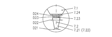
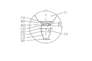
図4及び図4−1は、図1によるプラズマトーチでも使用できるような電極7を示す。この点において、エミッションインサート7.2は、電極ホルダ7.1から突出したセクション7.24とともに形成されている。外径D23が小さくなっているセクション7.23は、加工対象物(図示せず)の方向において、このセクション7.24と隣接している。このセクション7.23の後に円柱状のセクション7.22が続き、これにセクション7.21が隣接する。セクション7.21の形状は、加工対象物の方向に円錐状に先細になる円錐台である。この実施例では、外径D24及びD22は、同サイズであり、セクション7.23の外径D23より大きい。セクション7.21に形成されている前部端面の外径D21は、外径D23より小さく、当然ながら外径D22及びD24よりも小さい。
FIGS. 4 and 4-1 show an
図4−2に示された実施例が図4−1による実施例と異なる点は、セクション7.24の外径D24がセクション7.22の外径D22より大きいこと、並びに、外径D22及びD24の両方がセクション7.23の外径D23より大きいことである。 The embodiment shown in FIG. 4-2 differs from the embodiment according to FIG. 4-1 in that the outer diameter D24 of section 7.24 is larger than the outer diameter D22 of section 7.22, and that the outer diameter D22 and Both D24 are larger than the outer diameter D23 of section 7.23.
図4−3に示された実施例では、セクション7.22及び7.24の外径の関係が逆になっており、D22>D24>D23が成り立つ。 In the embodiment shown in FIG. 4-3, the relationship between the outer diameters of the sections 7.22 and 7.24 is reversed, and D22> D24> D23 holds.
図4−4は、D24=D23<D22となるように外径サイズが選択された実施例を示す。これは、エミッションインサート7.2が、セクション7.23の外径D23で電極ホルダ7.1内に固定されていることを意味する。 FIG. 4-4 shows an example in which the outer diameter size is selected such that D24 = D23 <D22. This means that the emission insert 7.2 is fixed in the electrode holder 7.1 with the outer diameter D23 of the section 7.23.
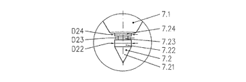
図4−5に示された実施例では、セクション7.24、7.23、及び7.22の各外径は、D24<D23<D22となるように選択されている。従って、最小外径は、電極ホルダ7.1のすぐ下に配置された領域7.24にあり、これによって、エミッションインサート7.2は、電極ホルダ7.1から突出している。 In the example shown in FIGS. 4-5, the outer diameters of sections 7.24, 7.23, and 7.22 are selected such that D24 <D23 <D22. The minimum outer diameter is therefore in the region 7.24, which is arranged immediately below the electrode holder 7.1, whereby the emission insert 7.2 protrudes from the electrode holder 7.1.
図4−6に示された実施例では、各外径は、D24=D22>D23となるように選択されている。 In the embodiment shown in FIGS. 4-6, each outer diameter is selected such that D24 = D22> D23.
図4−7に示された実施例でも、エミッションインサート7.2の、電極ホルダ7.1のすぐ背後に配置されているのは、外径が小さくなっているセクション7.23だけである。上記電極ホルダにはセクション7.21が隣接しており、セクション7.21は、加工対象物12の方向に円錐状に先細になっていて、その最大外径D22は、セクション7.23の外径D23より大きい。加工対象物12の方向を向いている、エミッションインサート7.2の端面は、円形であり、その外径D21は外径D23より小さい。
Also in the embodiment shown in FIGS. 4-7, only the section 7.23 with a reduced outer diameter is located in the emission insert 7.2 just behind the electrode holder 7.1. Section 7.21 is adjacent to the electrode holder, and section 7.21 tapers conically in the direction of
この実施例、並びに図4−6及び図4−8に示された実施例では、セクション7.23とセクション7.21との間に別のセクション7.22があってもよく、しかしながら、セクション7.22は、エミッションインサート7.2の長手軸方向において非常に短くてよい。この点において、その外径D22は、セクション7.21の最大外径D21と同サイズであってよい。 In this embodiment, and in the embodiments shown in FIGS. 4-6 and 4-8, there may be another section 7.22 between section 7.23 and section 7.21, but the section 7.22 may be very short in the longitudinal direction of the emission insert 7.2. In this regard, the outer diameter D22 may be the same size as the maximum outer diameter D21 of section 7.21.
図4−8による実施例では、セクション7.1は、円錐であり、加工対象物12の方向に先端を有する。
In the embodiment according to FIGS. 4-8, section 7.1 is a cone and has a tip in the direction of
図5及び図5−1も、裁頭円錐形のセクション7.21を有する電極7を示しており、これは、例えば、図4による実施例の場合と同様である。
FIGS. 5 and 5-1 also show an
図5−2による実施例では、円錐形のセクション7.21は、加工対象物の方向を向いた先端をエミッションインサート7.2の端部に有する円錐形である。 In the embodiment according to FIG. 5-2, the conical section 7.21 is conical with a tip directed towards the workpiece at the end of the emission insert 7.2.
図6から図6−4は、様々な形状の、外径が小さくなっているセクション7.23を有する実施例を示す。 Figures 6 to 6-4 show embodiments having sections 7.23 of various shapes and reduced outer diameter.
図6による実施例も、図4による実施例に対応しており、外径が小さくなっているセクション7.23が、矩形の断面を有する。 The embodiment according to FIG. 6 also corresponds to the embodiment according to FIG. 4, in which the section 7.23 with a reduced outer diameter has a rectangular cross section.
図6−1は、セクション7.22及び7.24からセクション7.23への移行が半径R1及びR2によって形成されている実施例を示す。図6−2による実施例では、セクション7.23の部分円形状の外側輪郭が前述の矩形形状とは異なって形成されるように、セクション7.23からセクション7.22への移行が面取りF1によって構成されており、セクション7.23の外径が半径R2によって構成されている。 FIG. 6-1 shows an embodiment in which the transition from sections 7.22 and 7.24 to section 7.23 is formed by radii R1 and R2. In the embodiment according to FIG. 6-2, the transition from section 7.23 to section 7.22 is chamfered F1 such that the partial outer contour of section 7.23 is formed differently than the previously described rectangular shape. The outer diameter of section 7.23 is formed by radius R2.
図6−3に示された実施例では、セクション7.23から隣接するセクション7.22及び7.24への移行が、面取りF1及びF2として形成されている。 In the embodiment shown in FIG. 6-3, the transition from section 7.23 to adjacent sections 7.22 and 7.24 is formed as chamfers F1 and F2.
図6−4は、セクション7.23全体が半径R3によって形成されていて、これに対応する丸い移行がセクション7.22及び7.24に向かって達成されている実施例を示す。 FIG. 6-4 shows an embodiment in which the entire section 7.23 is formed by a radius R3 and a corresponding round transition is achieved towards sections 7.22 and 7.24.
全ての実施例において、示されていない可能性として、個々のセクション7.21、7.22、7.23、及び7.24の、電極7の長手軸方向の長さを変化させて、更に、それらをそれぞれのプラズマトーチパラメータ(例えば、その出力)に適合させることを可能にすることが含まれる。
In all examples, the possibility of not being shown could vary the lengths of the individual sections 7.21, 7.22, 7.23 and 7.24 in the longitudinal direction of the
1 プラズマトーチヘッド
2 ノズルキャップ
3 プラズマガス送り込み
4 ノズル
4.1 ノズル流路
5 ノズルホルダ
6 電極マウント
7 電極
7.1 電極ホルダ
7.2 エミッションインサート
7.21 エミッションインサートのセクション1
7.22 エミッションインサートのセクション2
7.23 エミッションインサートのセクション3
7.24 エミッションインサートのセクション4
8 保護ノズルキャップホルダ
9 保護ノズルキャップ
9.1 二次ガスガイド
10 冷却液空間
11 冷却管
12 加工対象物
D21 エミッションインサート7.2のセクション1の直径
D22 エミッションインサート7.2のセクション2の直径
D23 エミッションインサート7.2のセクション3の直径
D24 エミッションインサート7.2のセクション4の直径
F 面取り
M プラズマトーチヘッド1及び電極7の中心軸
PG プラズマガス
R 半径
SG 二次ガス
WV 冷却液ヘッダ
WR 冷却液リターン
DESCRIPTION OF SYMBOLS 1 Plasma torch head 2
7.22 Emission Insert Section 2
7.23
7.24
8 Protective
Claims (13)
前記エミッションインサート(7.2)は、その長手軸方向に、他の2つのセクション(7.24及び7.22)の間に、又はあるセクション(7.21又は7.22又は7.24)の隣に配置された少なくとも1つのセクション(7.23)を有し、前記エミッションインサート(7.2)の回転対称設計において外径が小さくなっており、或いは、非回転対称のエミッションインサート(7)における断面が前記他のセクション(7.21、7.22、7.24)に対して小さくなっていることを特徴とする電極。 An electrode for a plasma cutting torch formed from an electrode holder (7.2) and an emission insert (7.2) connected to each other by a press-fitting method and / or a shape matching method,
The emission insert (7.2) is in the longitudinal direction, between the other two sections (7.24 and 7.22) or in one section (7.21 or 7.22 or 7.24) At least one section (7.23) arranged next to the outer diameter of the rotational insert of the emission insert (7.2), or a non-rotationally symmetric emission insert (7). ) In which the cross section is smaller than the other sections (7.21, 7.22, 7.24).
Use of an electrode according to any one of the preceding claims in a plasma torch, the plasma torch comprising at least one plasma torch head (1) comprising an electrode (7), the electrode (7 ) Is formed from the electrode holder (7.1) and the emission insert (7.2) together with the nozzle (4) and the gas feed for the plasma gas (PG), and the emission insert (7.2) Has a section (7.23), the section (7.23) with respect to at least one section (7.22 and / or 7.24) arranged next to the section (7.23) Use of electrodes with reduced outer diameter or cross section.
Applications Claiming Priority (2)
| Application Number | Priority Date | Filing Date | Title |
|---|---|---|---|
| EP12169342.8A EP2667689B1 (en) | 2012-05-24 | 2012-05-24 | Electrode for plasma cutting torch and use of same |
| EP12169342.8 | 2012-05-24 |
Publications (2)
| Publication Number | Publication Date |
|---|---|
| JP2014004629A true JP2014004629A (en) | 2014-01-16 |
| JP2014004629A5 JP2014004629A5 (en) | 2016-05-19 |
Family
ID=46178438
Family Applications (1)
| Application Number | Title | Priority Date | Filing Date |
|---|---|---|---|
| JP2013110128A Pending JP2014004629A (en) | 2012-05-24 | 2013-05-24 | Electrode for plasma cutting torches and use of the same |
Country Status (11)
| Country | Link |
|---|---|
| US (1) | US9073141B2 (en) |
| EP (1) | EP2667689B1 (en) |
| JP (1) | JP2014004629A (en) |
| KR (1) | KR102036815B1 (en) |
| CN (1) | CN103418897A (en) |
| BR (1) | BR102013012164A2 (en) |
| CA (1) | CA2815260C (en) |
| ES (1) | ES2707292T3 (en) |
| PL (1) | PL2667689T3 (en) |
| RU (1) | RU2621673C2 (en) |
| ZA (1) | ZA201302710B (en) |
Cited By (1)
| Publication number | Priority date | Publication date | Assignee | Title |
|---|---|---|---|---|
| KR101497052B1 (en) * | 2014-07-18 | 2015-02-27 | 김상국 | Apparatus for Cutting of Trash for Submersible Pump |
Families Citing this family (4)
| Publication number | Priority date | Publication date | Assignee | Title |
|---|---|---|---|---|
| USD775249S1 (en) * | 2015-04-01 | 2016-12-27 | Koike Sanso Kogyo Co., Ltd. | Inner nozzle for plasma torch |
| DE102017112821A1 (en) * | 2017-06-12 | 2018-12-13 | Kjellberg-Stiftung | Electrodes for gas- and liquid-cooled plasma torches, arrangement of an electrode and a cooling tube, gas guide, plasma torch, method for guiding gas in a plasma torch and method for operating a plasma torch |
| CN108561881B (en) * | 2018-03-16 | 2023-11-24 | 徐慕庆 | Cutting nozzle |
| DE102020125073A1 (en) | 2020-08-05 | 2022-02-10 | Kjellberg-Stiftung | Electrode for a plasma cutting torch, arrangement with the same, plasma cutting torch with the same and method for plasma cutting |
Citations (4)
| Publication number | Priority date | Publication date | Assignee | Title |
|---|---|---|---|---|
| JPS58170174U (en) * | 1982-05-10 | 1983-11-14 | 小池酸素工業株式会社 | Plasma torch electrode |
| JPH11254181A (en) * | 1997-12-23 | 1999-09-21 | Castolin Sa | Covering method of material |
| DE10144516A1 (en) * | 2001-09-10 | 2003-04-10 | Kjellberg Finsterwalde Elektro | Plasma burner, e.g. for cutting steel and aluminum, has one-piece nozzle, and electrode that protrudes or can protrude into pilot chamber or chambers formed by pilot bore |
| EP2457681A1 (en) * | 2010-11-30 | 2012-05-30 | Kjellberg-Stiftung | Torch for tungsten inert gas welding and electrode to be used in such torch |
Family Cites Families (11)
| Publication number | Priority date | Publication date | Assignee | Title |
|---|---|---|---|---|
| US3030490A (en) * | 1959-12-18 | 1962-04-17 | Union Carbide Corp | Multiple purpose arc torch apparatus |
| US4675493A (en) * | 1986-01-31 | 1987-06-23 | Eutectic Corporation | Gas-constricted arc nozzle |
| JPH07130490A (en) * | 1993-11-02 | 1995-05-19 | Komatsu Ltd | Plasma torch |
| US5624586A (en) * | 1995-01-04 | 1997-04-29 | Hypertherm, Inc. | Alignment device and method for a plasma arc torch system |
| DE29905658U1 (en) * | 1999-03-26 | 1999-07-22 | Trafimet Spa | High frequency plasma torch |
| US6559407B2 (en) * | 2001-04-05 | 2003-05-06 | Ford Global Technologies, Inc. | Cathode assembly for an electric arc spray apparatus |
| US7132619B2 (en) * | 2003-04-07 | 2006-11-07 | Thermal Dynamics Corporation | Plasma arc torch electrode |
| US7375302B2 (en) * | 2004-11-16 | 2008-05-20 | Hypertherm, Inc. | Plasma arc torch having an electrode with internal passages |
| US8101882B2 (en) * | 2005-09-07 | 2012-01-24 | Hypertherm, Inc. | Plasma torch electrode with improved insert configurations |
| DE102008018530B4 (en) | 2008-04-08 | 2010-04-29 | Kjellberg Finsterwalde Plasma Und Maschinen Gmbh | A nozzle for a liquid-cooled plasma torch, arrangement of the same and a nozzle cap and liquid-cooled plasma torch with such an arrangement |
| KR101002082B1 (en) * | 2010-06-17 | 2010-12-17 | 김태홍 | Electrode for plasma arc torch |
-
2012
- 2012-05-24 ES ES12169342T patent/ES2707292T3/en active Active
- 2012-05-24 PL PL12169342T patent/PL2667689T3/en unknown
- 2012-05-24 EP EP12169342.8A patent/EP2667689B1/en active Active
-
2013
- 2013-04-16 ZA ZA2013/02710A patent/ZA201302710B/en unknown
- 2013-05-07 CA CA2815260A patent/CA2815260C/en active Active
- 2013-05-07 RU RU2013120729A patent/RU2621673C2/en active
- 2013-05-16 BR BRBR102013012164-9A patent/BR102013012164A2/en active Search and Examination
- 2013-05-21 CN CN201310190102XA patent/CN103418897A/en active Pending
- 2013-05-22 US US13/899,635 patent/US9073141B2/en active Active
- 2013-05-23 KR KR1020130058077A patent/KR102036815B1/en active IP Right Grant
- 2013-05-24 JP JP2013110128A patent/JP2014004629A/en active Pending
Patent Citations (4)
| Publication number | Priority date | Publication date | Assignee | Title |
|---|---|---|---|---|
| JPS58170174U (en) * | 1982-05-10 | 1983-11-14 | 小池酸素工業株式会社 | Plasma torch electrode |
| JPH11254181A (en) * | 1997-12-23 | 1999-09-21 | Castolin Sa | Covering method of material |
| DE10144516A1 (en) * | 2001-09-10 | 2003-04-10 | Kjellberg Finsterwalde Elektro | Plasma burner, e.g. for cutting steel and aluminum, has one-piece nozzle, and electrode that protrudes or can protrude into pilot chamber or chambers formed by pilot bore |
| EP2457681A1 (en) * | 2010-11-30 | 2012-05-30 | Kjellberg-Stiftung | Torch for tungsten inert gas welding and electrode to be used in such torch |
Cited By (1)
| Publication number | Priority date | Publication date | Assignee | Title |
|---|---|---|---|---|
| KR101497052B1 (en) * | 2014-07-18 | 2015-02-27 | 김상국 | Apparatus for Cutting of Trash for Submersible Pump |
Also Published As
| Publication number | Publication date |
|---|---|
| BR102013012164A2 (en) | 2015-06-02 |
| US9073141B2 (en) | 2015-07-07 |
| EP2667689A1 (en) | 2013-11-27 |
| RU2621673C2 (en) | 2017-06-07 |
| RU2013120729A (en) | 2014-11-20 |
| PL2667689T3 (en) | 2019-04-30 |
| ZA201302710B (en) | 2013-12-23 |
| US20130313231A1 (en) | 2013-11-28 |
| ES2707292T3 (en) | 2019-04-03 |
| CN103418897A (en) | 2013-12-04 |
| KR102036815B1 (en) | 2019-11-26 |
| CA2815260C (en) | 2020-06-02 |
| KR20130132302A (en) | 2013-12-04 |
| CA2815260A1 (en) | 2013-11-24 |
| EP2667689B1 (en) | 2018-10-24 |
Similar Documents
| Publication | Publication Date | Title |
|---|---|---|
| JP5396609B2 (en) | Plasma device | |
| US9743504B2 (en) | Cooling pipes, electrode holders and electrode for an arc plasma torch | |
| KR101234874B1 (en) | Norzle for a liquid-cooled plasma torch, nozzle cap for a liquid-cooled plasma torch and plasam torch head with same | |
| US8575510B2 (en) | Nozzle for a liquid-cooled plasma burner, arrangement thereof with a nozzle cap, and liquid-cooled plasma burner comprising such an arrangement | |
| KR101607358B1 (en) | Electrode for a plasma burner | |
| US8921731B2 (en) | Protective nozzle cap, protective nozzle cap retainer, and arc plasma torch having said protective nozzle cap and or said protective nozzle cap retainer | |
| JP2014004629A (en) | Electrode for plasma cutting torches and use of the same | |
| KR20120032491A (en) | Nozzle for a liquid-cooled plasma torch and plasma torch head having the same | |
| US6191381B1 (en) | Tapered electrode for plasma arc cutting torches | |
| US11109475B2 (en) | Consumable assembly with internal heat removal elements | |
| EP2375876B1 (en) | Plasma cutting torch |
Legal Events
| Date | Code | Title | Description |
|---|---|---|---|
| A521 | Request for written amendment filed |
Free format text: JAPANESE INTERMEDIATE CODE: A523 Effective date: 20160324 |
|
| A621 | Written request for application examination |
Free format text: JAPANESE INTERMEDIATE CODE: A621 Effective date: 20160324 |
|
| A131 | Notification of reasons for refusal |
Free format text: JAPANESE INTERMEDIATE CODE: A131 Effective date: 20170228 |
|
| A977 | Report on retrieval |
Free format text: JAPANESE INTERMEDIATE CODE: A971007 Effective date: 20170228 |
|
| A521 | Request for written amendment filed |
Free format text: JAPANESE INTERMEDIATE CODE: A523 Effective date: 20170523 |
|
| A131 | Notification of reasons for refusal |
Free format text: JAPANESE INTERMEDIATE CODE: A131 Effective date: 20171024 |
|
| A521 | Request for written amendment filed |
Free format text: JAPANESE INTERMEDIATE CODE: A523 Effective date: 20171228 |
|
| A02 | Decision of refusal |
Free format text: JAPANESE INTERMEDIATE CODE: A02 Effective date: 20180327 |