CN103418897A - Electrode for plasma cutting torch and use of same - Google Patents
Electrode for plasma cutting torch and use of same Download PDFInfo
- Publication number
- CN103418897A CN103418897A CN201310190102XA CN201310190102A CN103418897A CN 103418897 A CN103418897 A CN 103418897A CN 201310190102X A CN201310190102X A CN 201310190102XA CN 201310190102 A CN201310190102 A CN 201310190102A CN 103418897 A CN103418897 A CN 103418897A
- Authority
- CN
- China
- Prior art keywords
- electrode
- cross
- reduced
- emission insert
- external diameter
- Prior art date
- Legal status (The legal status is an assumption and is not a legal conclusion. Google has not performed a legal analysis and makes no representation as to the accuracy of the status listed.)
- Pending
Links
Images


Classifications
-
- B—PERFORMING OPERATIONS; TRANSPORTING
- B23—MACHINE TOOLS; METAL-WORKING NOT OTHERWISE PROVIDED FOR
- B23K—SOLDERING OR UNSOLDERING; WELDING; CLADDING OR PLATING BY SOLDERING OR WELDING; CUTTING BY APPLYING HEAT LOCALLY, e.g. FLAME CUTTING; WORKING BY LASER BEAM
- B23K10/00—Welding or cutting by means of a plasma
-
- H—ELECTRICITY
- H05—ELECTRIC TECHNIQUES NOT OTHERWISE PROVIDED FOR
- H05H—PLASMA TECHNIQUE; PRODUCTION OF ACCELERATED ELECTRICALLY-CHARGED PARTICLES OR OF NEUTRONS; PRODUCTION OR ACCELERATION OF NEUTRAL MOLECULAR OR ATOMIC BEAMS
- H05H1/00—Generating plasma; Handling plasma
- H05H1/24—Generating plasma
- H05H1/26—Plasma torches
- H05H1/32—Plasma torches using an arc
- H05H1/34—Details, e.g. electrodes, nozzles
- H05H1/3442—Cathodes with inserted tip
-
- H—ELECTRICITY
- H05—ELECTRIC TECHNIQUES NOT OTHERWISE PROVIDED FOR
- H05H—PLASMA TECHNIQUE; PRODUCTION OF ACCELERATED ELECTRICALLY-CHARGED PARTICLES OR OF NEUTRONS; PRODUCTION OR ACCELERATION OF NEUTRAL MOLECULAR OR ATOMIC BEAMS
- H05H1/00—Generating plasma; Handling plasma
- H05H1/24—Generating plasma
- H05H1/26—Plasma torches
- H05H1/32—Plasma torches using an arc
- H05H1/34—Details, e.g. electrodes, nozzles
- H05H1/3478—Geometrical details
Abstract
The invention relates to an electrode for plasma torches for plasma cutting and to a use of the electrode for said plasma torch. The electrode in accordance with the invention for plasma cutting torches is formed from an electrode holder and an emission insert which are connected to one another in a force-fitted and/or shape-matched manner. The emission insert has at least one section along its longitudinal axis which is arranged between two other sections or next to a section which has a reduced outer diameter in a rotationally symmetrical design of the emission insert or has a reduced cross-sectional surface in a non-rotationally symmetrical emission insert with respect to the other section(s).
Description
Technical field
The present invention relates to a kind of electrode of the plasmatorch for the plasma cutting and relate to the purposes for the electrode of described plasmatorch.
Background technology
Plasma is by cation and anion, electronics and electric conductivity gas that excite and neutral atom and molecular high-temperature heating.
Various gas (for example monatomic argon gas and/or diatomic gas hydrogen, nitrogen, oxygen or air) is used as plasma gas.These gases are by energetic ion and the division of plasma arc.
The parameter of plasma jet can greatly be subject to the impact of the design of nozzle and electrode.These parameters of plasma jet are the flow velocity of jet diameter, temperature, energy density and gas for example.
In plasma cutting, plasma is subject to the restriction of nozzle usually, this nozzle can be air cooling or water-cooled.Can realize that thus energy density reaches 2x10
6W/cm
2.Temperature in plasma jet raises and reaches 30,000 ° of C, and this high flow rate in conjunction with gas can have very high cutting speed in all conductive materials.
Plasmatorch mainly comprises plasmatorch head 1, electrode 7 and nozzle 4; Other parts can be for the electrode mount of fixed electrode 7 (mount) 6, nozzle holder 5 with for the cap of spraying nozzle 2 of fixed nozzle 4.This plasma gas PG is fed in the space between electrode 7 and nozzle 4 by plasma gas guide 3 and finally by nozzle 4 nozzle passage 4.1 of flowing through.
In addition, current plasmatorch also has protectiveness cap of spraying nozzle 9 and secondary air guide 9.1, and secondary air SG is fed into plasma jet by this secondary air guide.Nozzle 4 and electrode 7 are usually cooling with the liquid coolant of for example water.
At present, the plasma cutting is a kind of for cutting the prescriptive procedure of conductive material, wherein according to cutting work, uses different gas and admixture of gas.
Thereby different electrode 7 and nozzle 4 are for this purpose.They were worn and must change subsequently in the operating period of plasmatorch.In order to use the plasmatorch for gas with various or admixture of gas, plasmatorch, electrode 7 and nozzle 4 are designed such that plasmatorch can be for different gas by changing electrode 7 and nozzle 4.
This design can also as can be seen from Figure 1, illustrate the example according to electrode of the present invention herein.
Such electrode has been described in DE10144516A1.Herein, electrode is fastened in support and the tip of electrode is stretched out and entered the nozzle cup.This electrode material consists of tungsten and is pressed in the support of conductive material (preferably copper or silver).These supports be generally water-cooled to realize effective heat radiation.
Plasmatorch with plasma gas import and secondary air import and nozzle and point electrode has also been described in DE102008018430B4.This electrode consists of electrode suppor and electrode insert; This electrode insert stretches out from electrode suppor.Yet, in this technical scheme, principal focal point is improve nozzle cooling.
In all these are arranged, the problem of existence is that service life and the cut quality of electrode is normally inadequate.
On the one hand, this electrode must be definitely by cooling well; But the high temperature that still must be implemented in the emitting surface place is used to form the secure transmission of the electronics of electric arc with realization.This emission should be carried out as far as possible equably from the teeth outwards, and this is conversely for having positive effect service life.In addition importantly, reach emission temperature in the short as far as possible time after electric arc is lighted.
In addition, this electrode should be designed such that as far as possible easily again to be equipped with plasmatorch between plasma gas used.Another requirement is highly concentric between emission insert and nozzle.This causes better cutting the service life of result and prolongation.
Summary of the invention
Therefore the purpose of this invention is to provide the electrode for plasmatorch, this plasmatorch can be preferably used for the plasma cutting, and it has been realized the service life increased and has had the response performance of the suitable temperature that reaches the electrode emission after electric arc is lighted of improvement simultaneously.
The electrode for plasmatorch of the feature by having claim 1 is realized according to purpose of the present invention.Claim 13 relates to the purposes according to electrode of the present invention.Use the feature in dependent claims can realize favourable embodiment and further development.Claim relates to a kind of plasmatorch.
Electrode for plasma cutting-torch according to the present invention is by forming to be pressed into cooperation and/or form fit mode electrode suppor connected to one another and to launch insert.Described emission insert has at least two parts (section) along its longitudinal axis.Aspect this, be arranged to be close to a part or be disposed in the external diameter reduced or the cross-sectional surface reduced in the emission insert of non-rotating symmetry at least one part between two parts has described emission insert Rotational Symmetry design with respect to other parts.
Described at least one part with the external diameter reduced or the cross-sectional surface reduced can be configured to preferably radially to be centered around the form of the groove of the lip-deep channel form of whole outer protective cover.
This cross section reduces in the zone of at least one part with the external diameter reduced or the cross section reduced equally by such design of emission insert.Therefore, current flowing in this zone increases, and makes with respect to the comparable electrical power of utilizing the electrode that do not have such part to realize, and the heating of emission insert is carried out in the short period of time.
Because another part is being treated on the direction of mach workpiece directly in abutting connection with having the external diameter reduced or having the part of the cross section reduced, in at least one edge that there is the external diameter reduced or there is the part of the cross section reduced, described another part has larger diameter or larger cross section, therefore relatively large surface can be used for the emission of electronics, and this has extra good effect in method for plasma cutting.
The part be disposed on the direction of workpiece to be cut after the part with the external diameter reduced or the cross section reduced can be at the upper conical convergent of the direction of this workpiece.On its whole length, it can be this situation.Yet an only part or another part of being arranged on the direction of workpiece can be the taper convergents.
Yet the part with constant outer diameter or constant cross-section can also be disposed between the part of part with the external diameter reduced or the cross section reduced and taper convergent.The part of the taper convergent that at least one is other may reside in such part place.This part can form the tip of this electrode.
The tip on the direction towards treating mach workpiece of emission insert can be conical, pyramid or have the form of frustum of a cone or the form of truncated pyramid.
Treating on the direction of mach workpiece that the emission insert for form of frusto-conical or truncated pyramid form has end face, the shape that this end face is circular surface or polygonal shape and be oriented to described workpiece and arrange.This end face should be less than all other external diameter or the cross sections that appear at all parts of emission in insert.
Described part with the external diameter reduced or the cross-sectional surface reduced is formed into the groove of rectangle, trapezoidal, fan-shaped or wedge shape form.
Can in the electrode suppor of the electrode according to the present invention, form the space of at least one hollow, cooling agent can be imported into the space of at least one hollow or be conducted through the space of at least one hollow.
Described electrode suppor should be made by the material with satisfactory electrical conductivity and thermal conductivity, preferably by silver (Ag) or copper (Cu) or both alloys, is made.Tungsten, tungsten alloy, hafnium or hafnium alloy that fusion temperature is greater than 2000 ° of C can be used as launching the material of insert (7.2).
Described part with the external diameter reduced or the cross section reduced is the form of groove with channel form of the external diameter reduced or the cross-sectional surface reduced, and described part should be less than external diameter or the cross section at least 20% that is close to the part that described part with the external diameter reduced or the cross section reduced directly arranges.
This emission insert should comprise solid material and there is no endoporus or there is no penetrating via.
Preferably, this emission insert should be by being pressed into the electrode suppor that is connected.Being pressed into cooperation can combine with utilizing that material is successional and be connected (preferably welding).
According to electrode of the present invention, can be used in plasmatorch, described plasmatorch is configured to have at least one plasmatorch head, this at least one plasmatorch head has by electrode suppor and the electrode that forms of emission insert, nozzle with for the gas feed of plasma gas, and wherein, existing part has the external diameter reduced or the cross section reduced with respect at least two parts that are close to this part layout.
The external diameter of emission insert can be at 1.5mm in the scope of 6mm.The external diameter of electrode suppor should be relatively large.
On the other hand, plasmatorch can be configured to have the conventionally form of various modification, and for example, this plasmatorch can relate to secondary air import or nozzle space.Electrode can be disposed in nozzle space.
The accompanying drawing explanation
To explain in more detail the present invention in conjunction with following example.Aspect this, can be with these features that can find out from example of form combination with one another of various variations.They are not limited to merely each example.
Shown in it:
Fig. 1 is the cutaway view of plasmatorch, in this plasmatorch, has inserted according to electrode of the present invention;
Fig. 2 is the example according to electrode of the present invention;
Fig. 3 .1 is three examples according to electrode of the present invention to Fig. 3 .3;
Fig. 4 is another example according to electrode of the present invention;
Fig. 4 .1 is six the other examples according to electrode of the present invention to Fig. 4 .8;
Fig. 5, Fig. 5 .1 to Fig. 5 .2 are three the other examples according to electrode of the present invention; With
Fig. 6 is five the other examples according to electrode of the present invention to Fig. 6 .4.
The specific embodiment
Comprise at least one plasmatorch head 1 at the plasmatorch shown in Fig. 1, described at least one plasmatorch head 1 has electrode 7, nozzle 4 and for the gas feed 3 of plasma gas PG.
This electrode 7 comprises electrode suppor 7.1 and emission insert 7.2, wherein, from electrode suppor 7.1, watch, the emission insert 7.2 of electrode 7 at least comprises part 7.23 and, towards the part 7.21 of the most advanced and sophisticated convergent of torch, the minimum diameter of part 7.23 is less than the maximum gauge of the part 7.21 of convergent.In Fig. 4, Fig. 4 .1, Fig. 4 .2, Fig. 4 .3, Fig. 4 .4, Fig. 4 .5, Fig. 4 .6, Fig. 5, Fig. 5 .1, Fig. 5 .2, Fig. 6, Fig. 6 .1, Fig. 6 .2, Fig. 6 .3 and Fig. 6 .4, the example to this has been shown.
Electrode 7 is threaded into electrode mount 6 and cooling internally by cooling medium by screw thread, and the inside of this cooling medium by the cooling tube 22 as coolant conduit (header) WV is admitted to and by directed the returning in space as cooling agent reflux line WR formation between the outside of cooling tube 11 and electrode mount 6.
Nozzle 4 keeps by cap of spraying nozzle 2, and sends into and flow between nozzle 4 and cap of spraying nozzle 2 by the directed cooling medium returned of cooling agent reflux line WR by coolant conduit WV.
Protectiveness cap of spraying nozzle 9 is around nozzle 4 and cap of spraying nozzle 2.Secondary air SG flows betwixt, the secondary air SG secondary air guide 9.1 of flowing through, and secondary air guide 9.1 separates protectiveness cap of spraying nozzle 9 and cap of spraying nozzle 2 and maintain a certain distance simultaneously.Aspect this, secondary air guide 9.1 can be designed such that to allow secondary air SG rotation.Protectiveness cap of spraying nozzle 9 is fixed by protectiveness cap of spraying nozzle support 8, and protectiveness cap of spraying nozzle support 8 is secured to the plasmatorch head by screw thread.
Can make plasma gas PG rotation by the plasma guide (this paper is not shown) be disposed between nozzle 4 and electrode 7.
Electrode 7 comprises electrode suppor 7.1 and emission insert 7.2.Emission insert 7.2 is fastened in electrode suppor 7.1.This can implement by the mode that is pressed into cooperation and form fit.Therefore realize between emission insert 7.2 and electrode suppor 7.1 that good heat shifts.Electrode suppor 7.1 can be water-cooled, and its inside can have the hollow space of cooling water flow warp.Electrode suppor 7.1 comprises the material (Cu, Ag) with thermal conductive resin and electric conductivity.The tungsten that can have doping (for example lanthanum) is used to launch insert 7.2.
Observe from electrode suppor 7.1, be positioned on emission insert 7.2 with at least one part 7.23 of part 7.21 adjacency towards the most advanced and sophisticated convergent of torch.Circular cylinder shaped portion 7.22 is disposed in therebetween.Aspect this, the minimum outer diameter of part 7.23 is less than the maximum gauge of part 7.22 or tapered portion 7.21.Part 7.21 can have frusto-conical, truncated pyramid shape, cone shape or pyramidal shape.
Part 7.23 can form the groove of channel form, and preferably, this groove radially is centered around the whole protective cover surface of electrode 7.
Emission insert 7.2 can also have a plurality of inserts.
The configuration of the emission insert 7.2 by comprising the part 7.23 with the external diameter reduced or the cross section reduced can be realized following statement:
● increase resistance and/or thermal resistance in the zone of part 7.23;
● reach thus sufficiently high emission temperature and there is enough large emitting surface for electric arc simultaneously;
● the emission temperature that reaches in addition the emission insert within a short period of time has enough large emitting surface for electric arc simultaneously;
● the side on the part of emitting surface does not have arc starting; There is thus the centrality preferably of longer service life, electric arc and cut quality preferably.
Aspect this, the method can be moved as follows:
● fight and can light thus arc maintenance (pilot arc) by the electrion between electrode and nozzle or high-frequency discharge origination point;
● from nozzle passage, plasma jet out makes the path ionization between plasmatorch and workpiece;
● can between electrode and workpiece, form minor arc subsequently, and this workpiece can be cut.
With respect to the collet design, utilize the screw-in of electrode 7 also can realize high centrality.Aspect this, electrode suppor 7.1 and emission insert 7.2(for example, by being pressed into or similar means) structure be favourable.Thus, can also between heteroid electrode, be easy to change.
Fig. 2 illustrates the example that comprises the electrode 7 of electrode suppor 7.1 and emission insert 7.2 according to of the present invention with schematic form, wherein electrode suppor 7.1 has external screw thread.
From Fig. 3 .1, can find out, electrode suppor 7.1 is for solid form and can have external screw thread, and electrode 7 can be connected to plasmatorch by this external screw thread.
In the example shown in Fig. 3 .2, cooling agent space 7.12 is formed simple blind hole at electrode suppor 7.1 places.In the example shown in Fig. 3 .3, cooling agent space 7.12 has favourable design, this is can pile up and be present in such zone for the material on the enough larger surface of heat radiation owing to having, and in this zone, emission insert 7.2 is connected to electrode suppor 7.1.
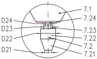
Fig. 4 and Fig. 4 .1 illustrate the electrode 7 that for example can also use in the plasmatorch according to Fig. 1.Aspect this, emission insert 7.2 is formed with the part 7.24 that reaches electrode suppor 7.1 outsides.Part 7.23 with the D outer diameter 23 reduced on the direction for the treatment of mach workpiece (not shown) in abutting connection with this part 7.24.Circular cylinder shaped portion 7.22 is this part 7.23 immediately, the part 7.21 of circular cylinder shaped portion 7.22 shape of the frustum of a cone of adjoins conical convergent on the direction of workpiece.In this example, the size of D outer diameter 24 and D outer diameter 22 is identical and is greater than the D outer diameter 23 of part 7.23.The D outer diameter 21 of the front end face formed at part 7.21 places is less than D outer diameter 23 and certainly also is less than D outer diameter 22 and D outer diameter 24.
In the example shown in Fig. 4 .2 and the difference according to the example of Fig. 4 .1, be, the D outer diameter 24 of part 7.24 is greater than the D outer diameter 22 of part 7.22, and D outer diameter 22 and D outer diameter 24 both are greater than the D outer diameter 23 of part 7.23.
In the example shown in Fig. 4 .3, the external diameter relation of part 7.22 and part 7.24 is contrary.It meets D22 > D24 > D23.
External diameter size in example shown in Fig. 4 .4 is selected and meets D24=D23<D22.The emission insert 7.2 that this means the part 7.23 with D outer diameter 23 is fastened in electrode suppor 7.1.
In the example shown in Fig. 4 .5, the external diameter of part 7.24, part 7.23 and part 7.22 is selected and meets D24<D23<D22.Therefore, minimum external diameter is present in zone 7.24, and zone 7.24 directly is arranged in the below of electrode suppor 7.1 and the outside that emission insert 7.2 stretches out electrode suppor 7.1 by this zone 7.24.
In the example shown in Fig. 4 .6, external diameter is selected and meets D24=D22 > D23.
The example again illustrated in Fig. 4 .7 only comprises the part 7.23 with the external diameter reduced, and this part 7.23 directly is arranged in the rear of the electrode suppor 7.1 at emission insert 7.2 places.Described electrode suppor adjacent part 7.21, part 7.21 is greater than the D outer diameter 23 of part 7.23 in the upper conical convergent of the direction of workpiece 12 and its maximum D outer diameter 21.There is circular shape and there is the D outer diameter 21 of D outer diameter of being less than 23 towards the end face of the emission insert 7.2 for the treatment of mach workpiece 12 directions.
In this example with in the example shown in Fig. 4 .6 and Fig. 4 .8, another part 7.22 can also be present between part 7.23 and part 7.21, yet part 7.22 can be very short on the direction of the longitudinal axis of emission insert 7.2.Aspect this, what the size of the D outer diameter 22 of part 7.22 can be with the maximum outside diameter D21 of part 7.21 is measure-alike.
In the example according to Fig. 4 .8, part 7.1 be taper and there is tip on the direction of workpiece 12.
Fig. 5 and Fig. 5 .1 illustrate the electrode 7 of the part 7.21 with frustum form again, as the situation in the example according to Fig. 4.
In the example according to Fig. 5 .2, tapering part 7.21 is tapers, and its end on the direction of workpiece at emission insert 7.2 has tip.
The example of the part with the external diameter reduced 7.23 that Fig. 6 forms shown with difference ground to Fig. 6 .4.
Again corresponding to the example according to Fig. 4, and there is the cross section that the part 7.23 that reduces external diameter has rectangle according to the example of Fig. 6.
In the example shown in Fig. 6 .1, the transition with radius R 1 and radius R 2 forming sections 7.22 and part 7.24 to part 7.23.In the example according to Fig. 6 .2, construct the transition of part 7.23 to part 7.22 with inclined-plane F1, and construct the external diameter of parts 7.23 with radius R 2, make part 7.23 form the fan-shaped outline different from above-described rectangular in form.
In the example shown in Fig. 6 .3, part 7.23 forms F1He inclined-plane, inclined-plane F2 to the transition of adjacent part 7.22 and part 7.24.
Fig. 6 .4 illustrates such example: with radius R 3, form whole parts 7.23 and realize thus the corresponding annular transition with part 7.22 and part 7.24.
In all examples, the possibility do not illustrated is included on the direction of longitudinal axis of electrode 7 and changes the length of various piece 7.21, part 7.22, part 7.23 and part 7.24 and can make in addition thus them be applicable to corresponding plasmatorch parameter, for example its power.
Reference numerals list:
1 plasmatorch head
2 cap of spraying nozzle
3 plasma imports
4 nozzles
4.1 nozzle passage
5 nozzle holders
6 electrode mounts
7 electrodes
7.1 electrode suppor
7.2 emission insert
7.21 the part 1 of emission insert
7.22 the part 2 of emission insert
7.23 the part 3 of emission insert
7.24 the part 4 of emission insert
8 protectiveness cap of spraying nozzle supports
9 protectiveness cap of spraying nozzle
9.1 secondary air guide
10 cooling agent spaces
11 cooling tubes
12 workpiece
The diameter of the part 1 of D21 emission insert 7.2
The diameter of the part 2 of D22 emission insert 7.2
The diameter of the part 3 of D23 emission insert 7.2
The diameter of the part 4 of D24 emission insert 7.2
The F inclined-plane
The central axis of M plasmatorch head 1 and electrode 7
The PG plasma gas
The R radius
The SG secondary air
The WV coolant conduit
WR cooling agent reflux line
Claims (13)
1. the electrode for plasma cutting-torch, described electrode is by coordinating and/or mode electrode suppor connected to one another (7.1) and emission insert (7.2) formation of form fit to be pressed into,
It is characterized in that, described emission insert (7.2) has at least one part (7.23) along the longitudinal axis of described emission insert, described at least one part (7.23) is disposed between other two parts (7.24 and 7.22) or is arranged to be close to the arbitrary part (7.22 or 7.24) in another part (7.21) or described other two parts, described at least one part (7.23) is with respect to other parts (7.21, 7.22, 7.24) there is the external diameter reduced in the design of the Rotational Symmetry of described emission insert (7.2) or the cross section reduced in the emission insert (7) in non-rotating symmetry.
2. electrode according to claim 1, is characterized in that, described at least one part (7.23) with the external diameter reduced or the cross section reduced for radial loop preferably around the form of the groove of the lip-deep channel form of whole outer protective cover.
3. electrode according to claim 1 and 2, it is characterized in that, towards the part (7.21) of tapered convergent on the direction of workpiece to be cut in abutting connection with thering is the described part (7.23) of the external diameter reduced or the cross section reduced, and the more close described workpiece to be cut of the part of described tapered convergent (7.21).
4. according to electrode in any one of the preceding claims wherein, it is characterized in that, the part (7.22) with constant outer diameter or constant cross-section is disposed between the part (7.21) of the described part (7.23) of the external diameter reduced had or the cross section reduced and taper convergent.
5. according to electrode in any one of the preceding claims wherein, it is characterized in that, the tip towards the direction for the treatment of mach workpiece of described emission insert (7.2) is made into cone shape, pyramidal shape or frusto-conical or truncated pyramid shape.
6. electrode according to claim 5, it is characterized in that, on the direction towards workpiece, the emission insert (7.21) of form of frusto-conical or truncated pyramid form has end face, described end face is formed the shape of circular surface or polygonal shape and arranges towards described workpiece, and the cross section of the described end face of circular surface or polygon surface is less than the cross section of all parts (7.21,7.22,7.23 and 7.24) that are present in described emission insert (7.2).
7. according to electrode in any one of the preceding claims wherein, it is characterized in that, the described part (7.23) with the external diameter reduced or the cross section reduced is formed into the groove of rectangle, trapezoidal or wedge shape or fan shape.
8. according to electrode in any one of the preceding claims wherein, it is characterized in that, the space of at least one hollow is formed in described electrode suppor (7.1), and cooling agent can be imported in the space of described at least one hollow and/or be guided through the space of described at least one hollow.
9. according to electrode in any one of the preceding claims wherein, it is characterized in that, described electrode suppor (7.1) is made by the material with satisfactory electrical conductivity and thermal conductivity, preferably by the alloy of Ag or Cu or Ag and Cu, made, and described emission insert (7.2) is made by tungsten, hafnium, tungsten alloy or hafnium alloy.
10. according to electrode in any one of the preceding claims wherein, it is characterized in that, described part (7.23) with the external diameter reduced or the cross section reduced has the form of groove of the channel form of the external diameter reduced or the cross section reduced, and described part (7.23) is less than external diameter or the cross section at least 20% that is close to the part (7.22 or 7.24) that described part (7.23) with the external diameter reduced or the cross section reduced directly arranges.
11. according to electrode in any one of the preceding claims wherein, it is characterized in that, described emission insert (7.2) comprises solid material and/or is connected to described electrode suppor (7.1) by being pressed into to coordinate.
12. according to electrode in any one of the preceding claims wherein, it is characterized in that, by edge grain (R1, R2, R3) and/or inclined-plane (F1 or F2), form described part (7.23) and the transition that is close to the part (7.22,7.24) that described part arranges.
13. the purposes according to electrode in any one of the preceding claims wherein in plasmatorch, wherein, described plasmatorch has at least one plasmatorch head (1), described at least one plasmatorch head (1) has the electrode (7) consisted of described electrode suppor (7.1) and described emission insert (7.2), nozzle (4) and for the gas feed of plasma gas (PG), and the part (7.23) be present in described emission insert (7.2) has the external diameter reduced or the cross section reduced with respect at least one part (7.22 and/or 7.24) that is close to described part (7.23) layout.
Applications Claiming Priority (2)
| Application Number | Priority Date | Filing Date | Title |
|---|---|---|---|
| EP12169342.8A EP2667689B1 (en) | 2012-05-24 | 2012-05-24 | Electrode for plasma cutting torch and use of same |
| EP12169342.8 | 2012-05-24 |
Publications (1)
| Publication Number | Publication Date |
|---|---|
| CN103418897A true CN103418897A (en) | 2013-12-04 |
Family
ID=46178438
Family Applications (1)
| Application Number | Title | Priority Date | Filing Date |
|---|---|---|---|
| CN201310190102XA Pending CN103418897A (en) | 2012-05-24 | 2013-05-21 | Electrode for plasma cutting torch and use of same |
Country Status (11)
| Country | Link |
|---|---|
| US (1) | US9073141B2 (en) |
| EP (1) | EP2667689B1 (en) |
| JP (1) | JP2014004629A (en) |
| KR (1) | KR102036815B1 (en) |
| CN (1) | CN103418897A (en) |
| BR (1) | BR102013012164A2 (en) |
| CA (1) | CA2815260C (en) |
| ES (1) | ES2707292T3 (en) |
| PL (1) | PL2667689T3 (en) |
| RU (1) | RU2621673C2 (en) |
| ZA (1) | ZA201302710B (en) |
Cited By (2)
| Publication number | Priority date | Publication date | Assignee | Title |
|---|---|---|---|---|
| CN108561881A (en) * | 2018-03-16 | 2018-09-21 | 徐慕庆 | A kind of cutting torch |
| CN110896687A (en) * | 2017-06-12 | 2020-03-20 | 卡尔伯格-基金会 | Electrode for gas-cooled and liquid-cooled plasma burners, arrangement of electrode and cooling tube, gas guiding device, plasma burner, method for guiding gas in plasma burner, and method for operating plasma burner |
Families Citing this family (3)
| Publication number | Priority date | Publication date | Assignee | Title |
|---|---|---|---|---|
| KR101497052B1 (en) * | 2014-07-18 | 2015-02-27 | 김상국 | Apparatus for Cutting of Trash for Submersible Pump |
| USD775249S1 (en) * | 2015-04-01 | 2016-12-27 | Koike Sanso Kogyo Co., Ltd. | Inner nozzle for plasma torch |
| DE102020125073A1 (en) | 2020-08-05 | 2022-02-10 | Kjellberg-Stiftung | Electrode for a plasma cutting torch, arrangement with the same, plasma cutting torch with the same and method for plasma cutting |
Citations (5)
| Publication number | Priority date | Publication date | Assignee | Title |
|---|---|---|---|---|
| CN87102295A (en) * | 1986-01-31 | 1987-10-28 | 尤泰克蒂克公司 | Gas-constricted arc nozzle |
| CN1134217A (en) * | 1993-11-02 | 1996-10-23 | 株式会社小松制作所 | Plasma torch |
| EP0927594A1 (en) * | 1997-12-23 | 1999-07-07 | Castolin S.A. | Method for coating materials |
| DE29905658U1 (en) * | 1999-03-26 | 1999-07-22 | Trafimet Spa | High frequency plasma torch |
| EP1248501A2 (en) * | 2001-04-05 | 2002-10-09 | Ford Global Technologies, Inc. | Cathode assembly for an electric arc spray apparatus |
Family Cites Families (10)
| Publication number | Priority date | Publication date | Assignee | Title |
|---|---|---|---|---|
| US3030490A (en) * | 1959-12-18 | 1962-04-17 | Union Carbide Corp | Multiple purpose arc torch apparatus |
| JPS58170174U (en) * | 1982-05-10 | 1983-11-14 | 小池酸素工業株式会社 | Plasma torch electrode |
| US5624586A (en) * | 1995-01-04 | 1997-04-29 | Hypertherm, Inc. | Alignment device and method for a plasma arc torch system |
| DE10144516B4 (en) | 2001-09-10 | 2004-03-25 | Kjellberg Finsterwalde Elektroden Und Maschinen Gmbh | plasma torch |
| US7132619B2 (en) * | 2003-04-07 | 2006-11-07 | Thermal Dynamics Corporation | Plasma arc torch electrode |
| US7375302B2 (en) * | 2004-11-16 | 2008-05-20 | Hypertherm, Inc. | Plasma arc torch having an electrode with internal passages |
| US8101882B2 (en) * | 2005-09-07 | 2012-01-24 | Hypertherm, Inc. | Plasma torch electrode with improved insert configurations |
| DE102008018530B4 (en) | 2008-04-08 | 2010-04-29 | Kjellberg Finsterwalde Plasma Und Maschinen Gmbh | A nozzle for a liquid-cooled plasma torch, arrangement of the same and a nozzle cap and liquid-cooled plasma torch with such an arrangement |
| KR101002082B1 (en) * | 2010-06-17 | 2010-12-17 | 김태홍 | Electrode for plasma arc torch |
| DE102010053721B4 (en) * | 2010-11-30 | 2014-05-15 | Kjellberg Stiftung - Rechtsfähige Stiftung des bürgerlichen Rechts | Torch for tungsten inert gas welding and electrode for use in such a burner |
-
2012
- 2012-05-24 ES ES12169342T patent/ES2707292T3/en active Active
- 2012-05-24 PL PL12169342T patent/PL2667689T3/en unknown
- 2012-05-24 EP EP12169342.8A patent/EP2667689B1/en active Active
-
2013
- 2013-04-16 ZA ZA2013/02710A patent/ZA201302710B/en unknown
- 2013-05-07 CA CA2815260A patent/CA2815260C/en active Active
- 2013-05-07 RU RU2013120729A patent/RU2621673C2/en active
- 2013-05-16 BR BRBR102013012164-9A patent/BR102013012164A2/en active Search and Examination
- 2013-05-21 CN CN201310190102XA patent/CN103418897A/en active Pending
- 2013-05-22 US US13/899,635 patent/US9073141B2/en active Active
- 2013-05-23 KR KR1020130058077A patent/KR102036815B1/en active IP Right Grant
- 2013-05-24 JP JP2013110128A patent/JP2014004629A/en active Pending
Patent Citations (5)
| Publication number | Priority date | Publication date | Assignee | Title |
|---|---|---|---|---|
| CN87102295A (en) * | 1986-01-31 | 1987-10-28 | 尤泰克蒂克公司 | Gas-constricted arc nozzle |
| CN1134217A (en) * | 1993-11-02 | 1996-10-23 | 株式会社小松制作所 | Plasma torch |
| EP0927594A1 (en) * | 1997-12-23 | 1999-07-07 | Castolin S.A. | Method for coating materials |
| DE29905658U1 (en) * | 1999-03-26 | 1999-07-22 | Trafimet Spa | High frequency plasma torch |
| EP1248501A2 (en) * | 2001-04-05 | 2002-10-09 | Ford Global Technologies, Inc. | Cathode assembly for an electric arc spray apparatus |
Cited By (4)
| Publication number | Priority date | Publication date | Assignee | Title |
|---|---|---|---|---|
| CN110896687A (en) * | 2017-06-12 | 2020-03-20 | 卡尔伯格-基金会 | Electrode for gas-cooled and liquid-cooled plasma burners, arrangement of electrode and cooling tube, gas guiding device, plasma burner, method for guiding gas in plasma burner, and method for operating plasma burner |
| CN110896687B (en) * | 2017-06-12 | 2023-06-23 | 卡尔伯格-基金会 | Electrode of plasma burner, gas guiding device and gas guiding method |
| CN108561881A (en) * | 2018-03-16 | 2018-09-21 | 徐慕庆 | A kind of cutting torch |
| CN108561881B (en) * | 2018-03-16 | 2023-11-24 | 徐慕庆 | Cutting nozzle |
Also Published As
| Publication number | Publication date |
|---|---|
| BR102013012164A2 (en) | 2015-06-02 |
| US9073141B2 (en) | 2015-07-07 |
| EP2667689A1 (en) | 2013-11-27 |
| RU2621673C2 (en) | 2017-06-07 |
| RU2013120729A (en) | 2014-11-20 |
| PL2667689T3 (en) | 2019-04-30 |
| ZA201302710B (en) | 2013-12-23 |
| US20130313231A1 (en) | 2013-11-28 |
| ES2707292T3 (en) | 2019-04-03 |
| KR102036815B1 (en) | 2019-11-26 |
| CA2815260C (en) | 2020-06-02 |
| KR20130132302A (en) | 2013-12-04 |
| CA2815260A1 (en) | 2013-11-24 |
| EP2667689B1 (en) | 2018-10-24 |
| JP2014004629A (en) | 2014-01-16 |
Similar Documents
| Publication | Publication Date | Title |
|---|---|---|
| US8921731B2 (en) | Protective nozzle cap, protective nozzle cap retainer, and arc plasma torch having said protective nozzle cap and or said protective nozzle cap retainer | |
| KR101225435B1 (en) | Norzle for a liquid-cooled plasma torch, nozzle cap for a liquid-cooled plasma torch and plasam torch head with same | |
| CN204867744U (en) | A weld assembly for gas protection arc welding | |
| JP5396609B2 (en) | Plasma device | |
| CN103418897A (en) | Electrode for plasma cutting torch and use of same | |
| CN102407399B (en) | Nozzle characteristic is used to regulate plasma arc cutting torch and the method for cutting torch flow | |
| KR101607358B1 (en) | Electrode for a plasma burner | |
| KR20110013376A (en) | Nozzle for a liquid-cooled plasma burner, arrangement thereof with a nozzle cap and liquid-cooled plasma burner comprising such an arrangement | |
| US5416296A (en) | Electrode for plasma arc torch | |
| US11109475B2 (en) | Consumable assembly with internal heat removal elements | |
| US9095037B2 (en) | Nozzle for a liquid-cooled plasma cutting torch with grooves | |
| US6498316B1 (en) | Plasma torch and method for underwater cutting | |
| JP7090074B2 (en) | Applications for nozzle protection caps, plasma arc torches with nozzle protection caps, and plasma arc torches | |
| CN105338724A (en) | V-shaped nozzle of plasma torch | |
| US20170332469A1 (en) | Plasma cutting torch assembly and use of wear parts in a plasma cutting torch assembly | |
| JP2011031252A (en) | Insert tip, plasma torch, and plasma machining device | |
| RU142250U1 (en) | PLASMOTRON FOR SPRAYING | |
| RU213469U1 (en) | PLASMATRON FOR ADDITIVE GROWING | |
| EP2375875B1 (en) | Swirler for plasma cutting torches | |
| KR20200115988A (en) | small plasma-machine for easy concersion of welding and cutting operations |
Legal Events
| Date | Code | Title | Description |
|---|---|---|---|
| C06 | Publication | ||
| PB01 | Publication | ||
| C10 | Entry into substantive examination | ||
| SE01 | Entry into force of request for substantive examination | ||
| RJ01 | Rejection of invention patent application after publication |
Application publication date: 20131204 |
|
| RJ01 | Rejection of invention patent application after publication |